
Introducing a Novel Rice Husk Combustion Technology for Maximizing Energy and Amorphous Silica Production Using a Prototype Hybrid Rice Husk Burner to Minimize Environmental Impacts and Health Risk

 and
and 
Abstract
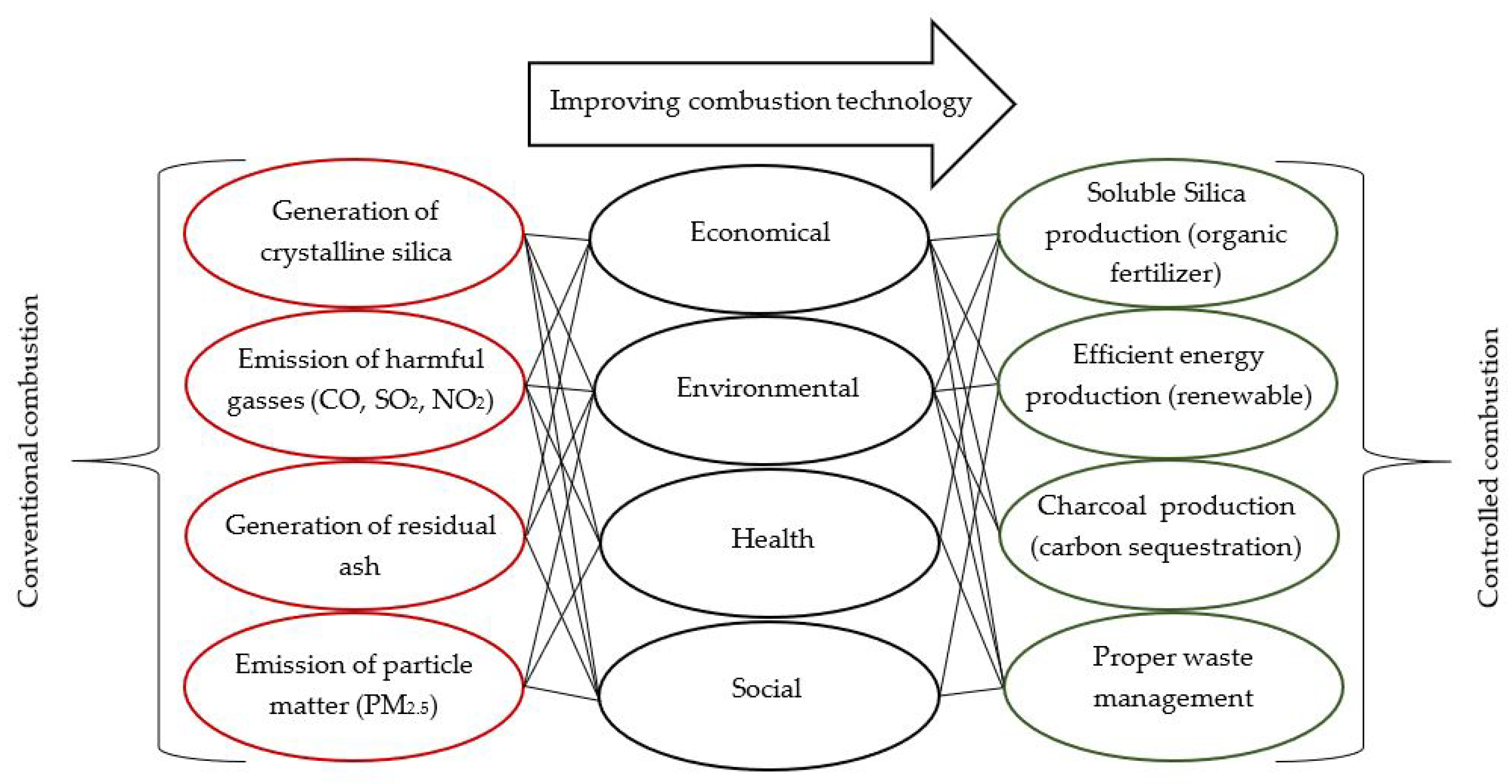
1. Introduction
2. Materials and Methods
2.1. Sample Collection
2.2. Experimental Setup
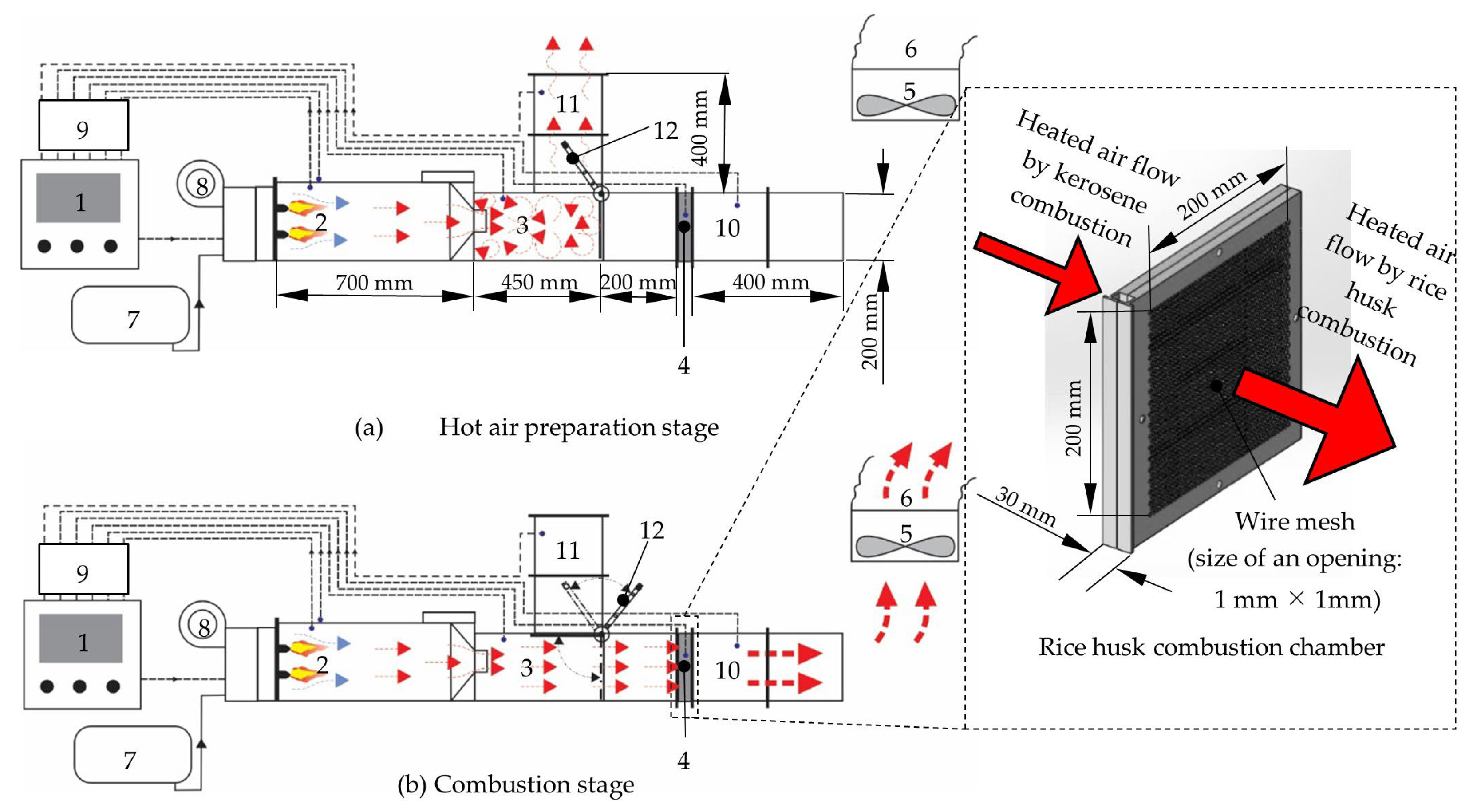
2.2.1. Specifications of the Prototype Hybrid Rice Husk Burner with a Fluidized Bed
2.2.2. Combustion Chamber of the Prototype Hybrid Rice Husk Burner (PHRB) with a Fluidized Bed
2.2.3. Initial Heat Supply and Combustion Process of the Prototype Hybrid Rice Husk Burner (PHRB) with a Fluidized Bed
2.3. Sample Preparation
2.4. Elemental Analysis of Rice Husk and Rice Husk Charcoal
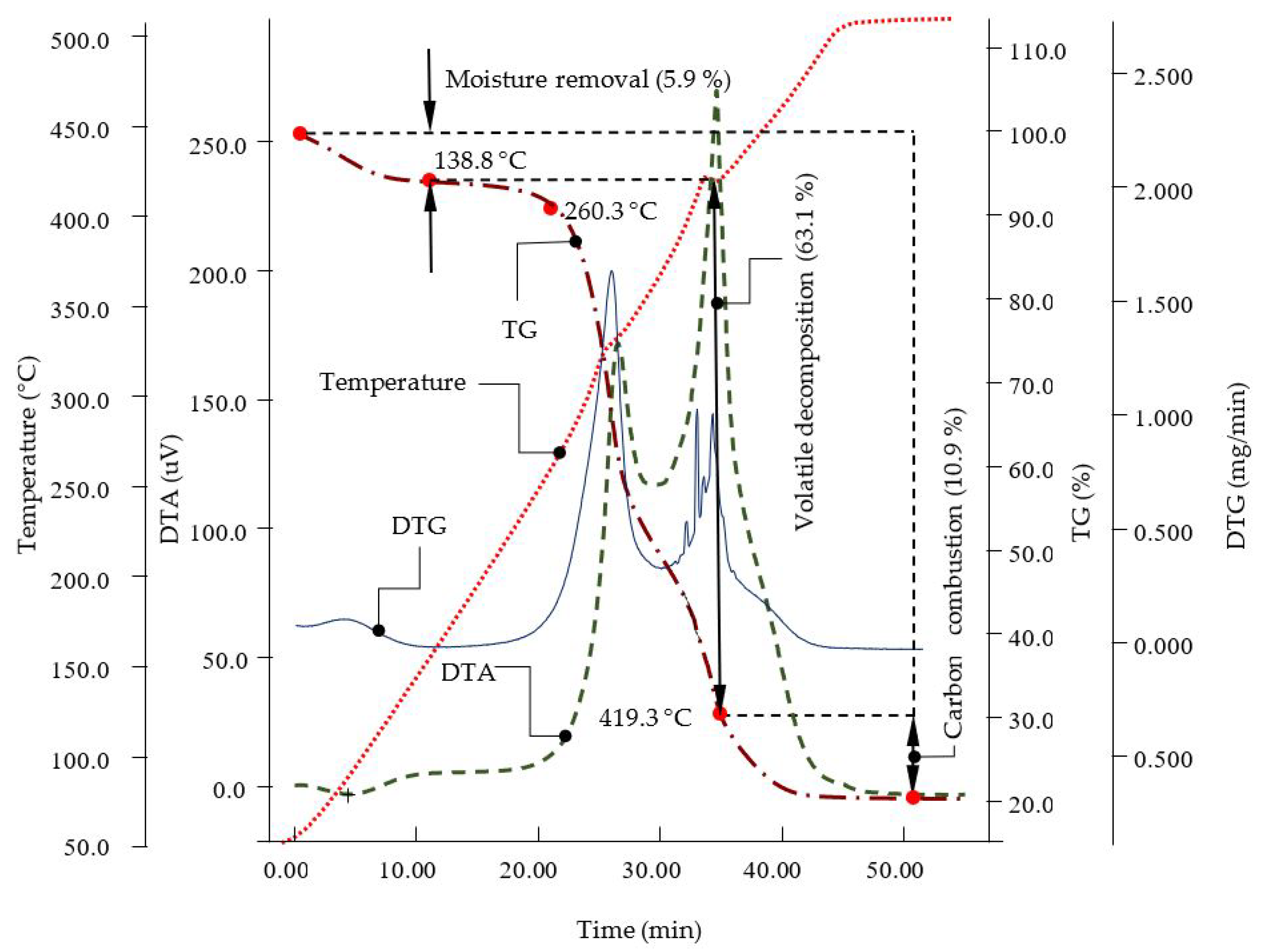
2.5. Differential Thermogravimetric Analysis of Rice Husk
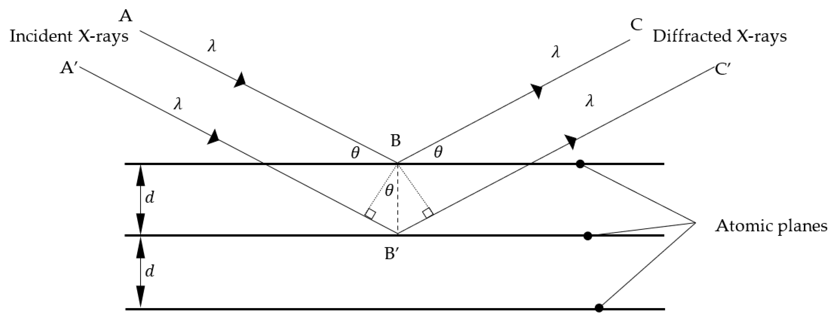
2.6. X-ray Powder Diffraction (XRD) Analysis of Rice Husk Charcoal
2.7. Flue Gas Analysis of the Rice Husk Combustion
2.8. Calculation of the Combustion Efficiency and Thermal Efficiency
3. Results and Discussion
3.1. Elemental Analysis of Rice Husk
3.2. Differential Thermogravimetric Analysis of Rice Husk
3.3. X-ray Powder Diffraction Analysis of Rice Husk Charcoal
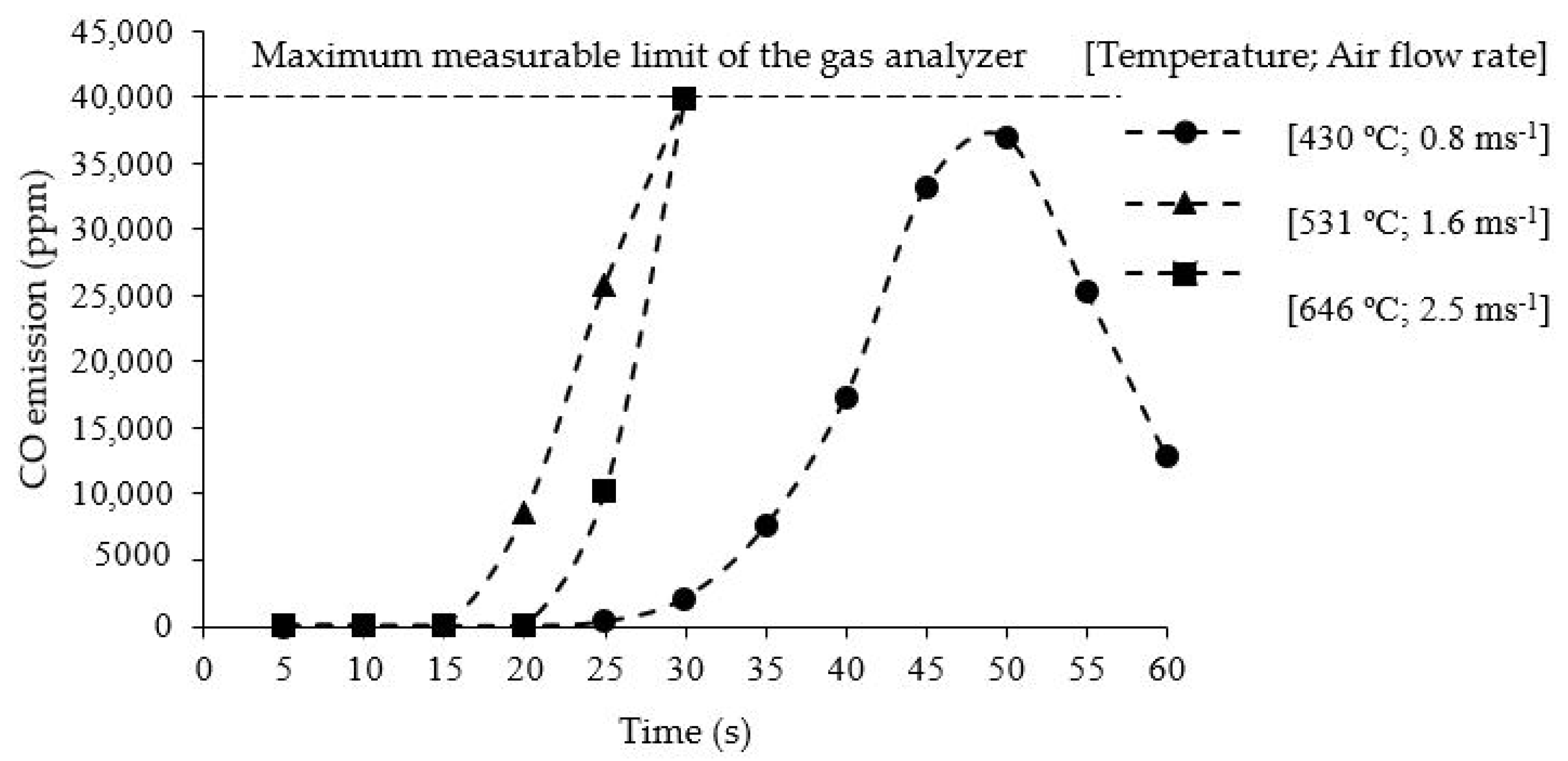
3.4. Flue Gas Analysis of Rice Husk Combustion
3.5. Elemental Analysis of Rice Husk Charcoal
3.6. Combustion Efficiency and Thermal Efficiency
3.7. CO Emissions and Charcoal Production
4. Conclusions
Author Contributions
Funding
Data Availability Statement
Acknowledgments
Conflicts of Interest
Nomenclature
| Combustion efficiency | |
| Thermal efficiency | |
| θ | Angle of incidence (°) |
| λ | Wavelength (m) |
| Al2O3 | Aluminum oxide |
| C | Carbon |
| CH4 | Methane |
| CO | Carbon monoxide |
| CO2 | Carbon dioxide |
| Cu | Copper |
| Kerosene consumption (Lh−1) | |
| d | Interplanar spacing of crystal (m) |
| DTA | Differential thermal analysis (uV) |
| DTG | Rate of weight change (mg/min) |
| Formation enthalpy of carbon monoxide (kJmol−1) | |
| Formation enthalpy of carbon dioxide (kJmol−1) | |
| H | Hydrogen |
| Calorific value of kerosene (MJL−1) | |
| Molecular weight (gmol−1) | |
| n | Order of reflection |
| N | Nitrogen |
| NO2 | Nitrogen dioxide |
| N2O | Nitrous oxide |
| O2 | Oxygen |
| O3 | Ozone |
| OH | Hydroxide |
| PHRB | Prototype hybrid rice husk burner |
| PM | Particle matter |
| Pressure at the point of measurement (hPa) | |
| Production of carbon dioxide (mol) | |
| Production of carbon dioxide under complete combustion (mol) | |
| Production of carbon monoxide (mol) | |
| S | Sulfur |
| SO2 | Sulfur dioxide |
| SiO2 | Silicon dioxide |
| Time duration of kerosene combustion (h) | |
| Temperature of the system (°C) | |
| TG | Thermo-gravimetry (%) |
| XRD | X-ray powder diffraction |
Appendix A

| Temperature and Airflow Rate Combination of the Experiment | Combustion Time Duration | Sample Bulk Density | Silica Crystallization | Availability of Amorphous Silica in Charcoal (Considering 20% of Silica in Rice Husk) | Maximum Sample Temperature During Combustion | Peak CO emission | Carbon Content in Charcoal (wt%) |
|---|---|---|---|---|---|---|---|
| A; 430 °C; 0.8 ms−1 | 30 s | 125 kgm−3 | - | 0.010 kg | 565.4 °C | 10,097 ppm | 4.60% |
| 175 kgm−3 | - | 0.014 kg | 745.7 °C | 2,882 ppm | 9.64% | ||
| 225 kgm−3 | Non-crystallized | 0.018 kg | 749.4 °C | 8,370 ppm | 21.78% | ||
| 10 min | 225 kgm−3 | Non-crystallized | 0.018 kg | 763.7 °C | 22,598 ppm | - | |
| 30 min | 225 kgm−3 | - | - | - | - | - | |
| 461 °C; 1.3 ms−1 | 30 s | 125 kgm−3 | - | - | - | - | - |
| 175 kgm−3 | - | - | - | - | - | ||
| 225 kgm−3 | Non-crystallized | 0.018 kg | - | - | - | ||
| 10 min | 225 kgm−3 | Non-crystallized | 0.018 kg | 750.1 °C | Over 40,000 ppm | - | |
| 30 min | 225 kgm−3 | - | - | - | - | - | |
| 494 °C; 1.4 ms−1 | 30 s | 125 kgm−3 | - | - | - | - | - |
| 175 kgm−3 | - | - | - | - | - | ||
| 225 kgm−3 | Non-crystallized | 0.018 kg | - | - | - | ||
| 10 min | 225 kgm−3 | Non-crystallized | 0.018 kg | 568.5 °C | Over 40,000 ppm | - | |
| 30 min | 225 kgm−3 | - | - | - | - | ||
| B; 531 °C; 1.6 ms−1 | 30 s | 125 kgm−3 | - | 0.010 kg | 754.9 °C | 31,398 ppm | 4.09% |
| 175 kgm−3 | - | 0.014 kg | 761.1 °C | 32,195 ppm | 6.29% | ||
| 225 kgm−3 | Non-crystallized | 0.018 kg | 813.1 °C | 30,862 ppm | 6.13% | ||
| 10 min | 225 kgm−3 | Non-crystallized | 0.018 kg | 788.9 °C | Over 40,000 ppm | - | |
| 30 min | 225 kgm−3 | Non-crystallized | 0.018 kg | - | - | - | |
| 587 °C; 1.8 ms−1 | 30 s | 125 kgm−3 | - | - | - | - | - |
| 175 kgm−3 | - | - | - | - | - | ||
| 225 kgm−3 | - | - | - | - | - | ||
| 10 min | 225 kgm−3 | Non-crystallized | 0.018 kg | 758.7 °C | - | - | |
| 30 min | 225 kgm−3 | Non-crystallized | 0.018 kg | - | - | - | |
| 623 °C; 2.3 ms−1 | 30 s | 125 kgm−3 | - | - | - | - | - |
| 175 kgm−3 | - | - | - | - | - | ||
| 225 kgm−3 | - | - | - | - | - | ||
| 10 min | 225 kgm−3 | Non-crystallized | 0.018 kg | 713.3 °C | - | - | |
| 30 min | 225 kgm−3 | Non-crystallized | 0.018 kg | - | - | - | |
| 621 °C; 2.4 ms−1 | 30 s | 125 kgm−3 | - | - | - | - | - |
| 175 kgm−3 | - | - | - | - | - | ||
| 225 kgm−3 | - | - | - | - | - | ||
| 10 min | 225 kgm−3 | Non-crystallized | 0.018 kg | 818.6 °C | - | - | |
| 30 min | 225 kgm−3 | Non-crystallized | 0.018 kg | - | - | - | |
| C; 646 °C; 2.5 ms−1 | 30 s | 125 kgm−3 | - | 0.010 kg | 768.2 °C | 23,255 ppm | 6.88% |
| 175 kgm−3 | - | 0.014 kg | 818.6 °C | 26,820 ppm | 7.53% | ||
| 225 kgm−3 | - | 0.018 kg | 830.3 °C | 34,811 ppm | 5.66% | ||
| 10 min | 225 kgm−3 | Non-crystallized | 0.018 kg | - | Over 40,000 ppm | - | |
| 30 min | 225 kgm−3 | Crystallized | - | - | - | - | |
| 690 °C; 2.6 ms−1 | 30 s | 125 kgm−3 | - | - | - | - | - |
| 175 kgm−3 | - | - | - | - | - | ||
| 225 kgm−3 | - | - | - | - | - | ||
| 10 min | 225 kgm−3 | Non-crystallized | 0.018 kg | - | Over 40,000 ppm | - | |
| 30 min | 225 kgm−3 | Crystallized | - | - | - |
Appendix B

References
- Reaño, R.L. Assessment of environmental impact and energy performance of rice husk utilization in various biohydrogen production pathways. Bioresour. Technol. 2020, 299, 122590. [Google Scholar] [CrossRef]
- Daifullah, A.A.M.; Girgis, B.S.; Gad, H.M.H. Utilization of agro-residues (rice husk) in small waste water treatment plans. Mater. Lett. 2003, 57, 1723–1731. [Google Scholar] [CrossRef]
- Steven, S.; Restiawaty, E.; Bindar, Y. Routes for energy and bio-silica production from rice husk: A comprehensive review and emerging prospect. Renew. Sustain. Energy Rev. 2021, 149, 111329. [Google Scholar] [CrossRef]
- Karam, D.S.; Nagabovanalli, P.; Rajoo, K.S.; Ishak, F.C.; Abdu, A.; Rosli, Z.; Muharam, F.M.; Zulperi, D. An overview on the preparation of rice husk biochar, factors affecting its properties, and its agriculture application. J. Saudi Soc. Agric. Sci. 2022, 21, 149–159. [Google Scholar] [CrossRef]
- Koyama, S.; Katagiri, T.; Minamikawa, K.; Kato, M.; Hayashi, H. Effects of rice husk charcoal application on rice yield, methane emission, and soil carbon sequestration in andosol paddy soil. Japan Agric. Res. Q. 2016, 50, 319–327. [Google Scholar] [CrossRef]
- Koyama, S.; Hayashi, H. Rice yield and soil carbon dynamics over three years of applying rice husk charcoal to an Andosol paddy field. Plant Prod. Sci. 2017, 20, 176–182. [Google Scholar] [CrossRef]
- Koyama, S.; Hayashi, H. Effects of single and successive applications of rice husk charcoal on paddy soil carbon content and rice productivity during two cropping seasons. Soil Sci. Plant Nutr. 2019, 65, 196–202. [Google Scholar] [CrossRef]
- Singh, C.; Tiwari, S.; Gupta, V.K.; Singh, J.S. The effect of rice husk biochar on soil nutrient status, microbial biomass and paddy productivity of nutrient poor agriculture soils. Catena 2018, 171, 485–493. [Google Scholar] [CrossRef]
- Meena, V.D.; Dotaniya, M.L.; Coumar, V.; Rajendiran, S.; Ajay; Kundu, S.; Subba, R.A. A case for silicon fertilization to improve crop yields in tropical soils. Proc. Natl. Acad. Sci. India Sect. B Biol. Sci. 2014, 84, 505–518. [Google Scholar] [CrossRef]
- Ankyu, E.; Kubota, Y.; Noguchi, R. Eluted soluble silica content in rice husk charcoal produced by rice husk burner. J. Japan Inst. Energy 2017, 96, 217–227. [Google Scholar] [CrossRef]
- Tateda, M. Production and effectiveness of amorphous silica fertilizer from rice husks using a sustainable local energy system. J. Sci. Res. Reports 2016, 9, 1–12. [Google Scholar] [CrossRef] [PubMed]
- Nagrale, S.D.; Hajare, H.; Modak, P.R. Utilization of rice husk ash. Int. J. Eng. Res. Appl. 2012, 2, 42. [Google Scholar]
- Mai Thao, P.T.; Kurisu, K.H.; Hanaki, K. Greenhouse gas emission mitigation potential of rice husks for An Giang province, Vietnam. Biomass Bioenergy 2011, 35, 3656–3666. [Google Scholar] [CrossRef]
- Shinohara, Y.; Kohyama, N. Quantitative analysis of tridymite and cristobalite crystallized in rice husk ash by heating. Ind. Health 2004, 42, 277–285. [Google Scholar] [CrossRef]
- Li, Y.; Ma, Z.; Han, T.; Quan, W.; Wang, J.; Zhou, H.; Dong, F. Long-term declining in carbon monoxide (CO) at a rural site of Beijing during 2006–2018 implies the improved combustion efficiency and effective emission control. J. Environ. Sci. 2022, 115, 432–442. [Google Scholar] [CrossRef] [PubMed]
- Royer, S.; Duprez, D. Catalytic oxidation of carbon monoxide over transition metal oxides. ChemCatChem. 2011, 3, 24–65. [Google Scholar] [CrossRef]
- Guo, F.; Zhong, Z. Co-combustion of anthracite coal and wood pellets: Thermodynamic analysis, combustion efficiency, pollutant emissions and ash slagging. Environ. Pollut. 2018, 239, 21–29. [Google Scholar] [CrossRef]
- Abah, E.O.; Iwai, K.; Sakurai, K.; Noguchi, R. Comparative Real-time Assessment of Particulate Matter Emissions in Rice Husk Combustion. J. Japan Inst. Energy 2018, 97, 222–225. [Google Scholar] [CrossRef]
- Quispe, I.; Navia, R.; Kahhat, R. Energy potential from rice husk through direct combustion and fast pyrolysis: A review. Waste Manag. 2017, 59, 200–210. [Google Scholar] [CrossRef]
- Madhiyanon, T.; Sathitruangsak, P.; Soponronnarit, S. Combustion characteristics of rice-husk in a short-combustion-chamber fluidized-bed combustor (SFBC). Appl. Therm. Eng. 2010, 30, 347–353. [Google Scholar] [CrossRef]
- Prasara-A, J.; Gheewala, S.H. Sustainable utilization of rice husk ash from power plants: A review. J. Clean. Prod. 2017, 167, 1020–1028. [Google Scholar] [CrossRef]
- Fernandes, I.J.; Calheiro, D.; Kieling, A.G.; Moraes, A.M.; Rocha, T.L.A.C.; Brehm, F.A.; Modolo, R.C.E. Characterization of rice husk ash produced using different biomass combustion techniques for energy. Fuel 2016, 165, 351–359. [Google Scholar] [CrossRef]
- Abah, E.O.; Ahamed, T.; Noguchi, R. Catalytic temperature effects on conversion efficiency of pm 2.5 and gaseous emissions from rice husk combustion. Energies 2021, 14, 6131. [Google Scholar] [CrossRef]
- Blissett, R.; Sommerville, R.; Rowson, N.; Jones, J.; Laughlin, B. Valorisation of rice husks using a TORBED® combustion process. Fuel Process. Technol. 2017, 159, 247–255. [Google Scholar] [CrossRef]
- Duan, F.; Chyang, C.S.; Lin, C.W.; Tso, J. Experimental study on rice husk combustion in a vortexing fluidized-bed with flue gas recirculation (FGR). Bioresour. Technol. 2013, 134, 204–211. [Google Scholar] [CrossRef]
- Albina, D.O. Emissions from multiple-spouted and spout-fluid fluidized beds using rice husks as fuel. Renew. Energy 2006, 31, 2152–2163. [Google Scholar] [CrossRef]
- Gajera, Z.R.; Verma, K.; Tekade, S.P.; Sawarkar, A.N. Kinetics of co-gasification of rice husk biomass and high sulphur petroleum coke with oxygen as gasifying medium via TGA. Bioresour. Technol. Rep. 2020, 11, 100479. [Google Scholar] [CrossRef]
- Khan, H.; Yerramilli, A.S.; D’Oliveira, A.; Alford, T.L.; Boffito, D.C.; Patience, G.S. Experimental methods in chemical engineering: X-ray diffraction spectroscopy—XRD. Can. J. Chem. Eng. 2020, 98, 1255–1266. [Google Scholar] [CrossRef]
- GASTEC. Concentration Unit Conversion. GASTEC Corporation. 2022. Available online: https://www.gastec.co.jp/en/technology/knowledge/concentration/ (accessed on 21 July 2022).
- Warnatz, J.; Maas, U.; Dibble, R.W. Combustion (Physical and Chemical Fundamentals, Modeling and Simulation, Experiments, Pollutant Formation), 4th ed.; Springer: Berlin/Heidelberg, Germany, 2006; pp. 42–43. [Google Scholar]
- CGER: National Greenhouse Gas Inventory Report of Japan. 2021. Available online: https://unfccc.int/documents/271503?gclid=CjwKCAiAhqCdBhB0EiwAH8M_Gu00eWENe1hcOGxw8ZiUI-TM2nUzmMz30HIFTIZn8En2KcGDSlMNsRoCz0YQAvD_BwE (accessed on 15 July 2022).
- Shafi, S.; Khelif, B.Y. Environmental Monitoring of Ambient Outdoor, Indoor Air Quality Pollutants, PM 10 and PM 2.5 Conducted to Evaluate Its Impact Analysis and Quantification in Industrial Area of Dammam, KSA. J. Geosci. Environ. Prot. 2021, 9, 100–114. [Google Scholar] [CrossRef]
- Hasegawa, M. Ellingham Diagram. Treatise Process Metall. 2014, 1, 507–516. [Google Scholar] [CrossRef]
- Armesto, L.; Bahillo, A.; Veijonen, K.; Cabanillas, A.; Otero, J. Combustion behaviour of rice husk in a bubbling fluidised bed. Biomass Bioenergy 2002, 23, 171–179. [Google Scholar] [CrossRef]


| Specification/Detail | Range | Controlling Factor |
|---|---|---|
| Kerosene consumption (Lh−1) | 2.20–9.00 | Temperature from 400 °C to 700 °C |
| Blower rotation (rpm) | 2295–6023 | Airflow from 0.5 ms−1 to 2.6 ms−1 |
| Capacity of the combustion chamber (m3) | 0.04 | Sample density from 125 kgm−3 to 225 kgm−3 |
| Carbon (C) | Hydrogen (H) | Nitrogen (N) | Sulfur (S) | Others * |
|---|---|---|---|---|
| 35.21 | 5.05 | 0.42 | 0.14 | 59.18 |
| Moisture Removal | Volatile Decomposition | Carbon Combustion | Total Weight Loss | Ash Content |
|---|---|---|---|---|
| 5.9 | 63.1 | 10.9 | 79.9 | 20.1 |
| Combustion Conditions (Temperature; Air Flow Rate; Bulk Density) for 30 s Combustion Time Duration | Maximum Sample Temperature (°C) | Silica Crystallization | Carbon Content in Charcoal (Dry wt%) | Combustion Efficiency | Thermal Efficiency |
|---|---|---|---|---|---|
| 430 °C; 0.8 ms−1; | |||||
| 125 kgm−3 | 565.4 | Not detected | 4.60 | 0.90 | 0.59 |
| 175 kgm−3 | 745.7 | Not detected | 9.64 | 0.99 a | 0.87 |
| 225 kgm−3 | 749.4 | Not detected | 21.78 | 0.92 | 0.94 b |
| 531 °C; 1.6 ms−1; | |||||
| 125 kgm−3 | 754.9 | Not detected | 4.09 | 0.90 | 0.34 |
| 175 kgm−3 | 761.1 | Not detected | 6.29 | 0.89 | 0.47 |
| 225 kgm−3 | 813.1 | Not detected | 6.13 | 0.87 | 0.59 |
| 646 °C; 2.5 ms−1; | |||||
| 125 kgm−3 | 768.2 | Not detected | 6.88 | 0.87 | 0.19 d |
| 175 kgm−3 | 818.6 | Not detected | 7.53 | 0.87 | 0.26 |
| 225 kgm−3 | 830.3 | Not detected | 5.66 | 0.86 c | 0.34 |
Disclaimer/Publisher’s Note: The statements, opinions and data contained in all publications are solely those of the individual author(s) and contributor(s) and not of MDPI and/or the editor(s). MDPI and/or the editor(s) disclaim responsibility for any injury to people or property resulting from any ideas, methods, instructions or products referred to in the content. |
© 2023 by the authors. Licensee MDPI, Basel, Switzerland. This article is an open access article distributed under the terms and conditions of the Creative Commons Attribution (CC BY) license (https://creativecommons.org/licenses/by/4.0/).
Share and Cite
Piyathissa, S.D.S.; Kahandage, P.D.; Namgay; Zhang, H.; Noguchi, R.; Ahamed, T. Introducing a Novel Rice Husk Combustion Technology for Maximizing Energy and Amorphous Silica Production Using a Prototype Hybrid Rice Husk Burner to Minimize Environmental Impacts and Health Risk. Energies 2023, 16, 1120. https://doi.org/10.3390/en16031120
Piyathissa SDS, Kahandage PD, Namgay, Zhang H, Noguchi R, Ahamed T. Introducing a Novel Rice Husk Combustion Technology for Maximizing Energy and Amorphous Silica Production Using a Prototype Hybrid Rice Husk Burner to Minimize Environmental Impacts and Health Risk. Energies. 2023; 16(3):1120. https://doi.org/10.3390/en16031120
Chicago/Turabian StylePiyathissa, S. D. S., P. D. Kahandage, Namgay, Hao Zhang, Ryozo Noguchi, and Tofael Ahamed. 2023. "Introducing a Novel Rice Husk Combustion Technology for Maximizing Energy and Amorphous Silica Production Using a Prototype Hybrid Rice Husk Burner to Minimize Environmental Impacts and Health Risk" Energies 16, no. 3: 1120. https://doi.org/10.3390/en16031120
APA StylePiyathissa, S. D. S., Kahandage, P. D., Namgay, Zhang, H., Noguchi, R., & Ahamed, T. (2023). Introducing a Novel Rice Husk Combustion Technology for Maximizing Energy and Amorphous Silica Production Using a Prototype Hybrid Rice Husk Burner to Minimize Environmental Impacts and Health Risk. Energies, 16(3), 1120. https://doi.org/10.3390/en16031120