Review

A Literature Review of the Positive Displacement Compressor: Current Challenges and Future Opportunities

Institute of Innovation, Science and Sustainability, Federation University Australia, Mount Helen, VIC 3353, Australia
*
Author to whom correspondence should be addressed.
Energies 2023, 16(20), 7035; https://doi.org/10.3390/en16207035
Submission received: 18 August 2023 / Revised: 30 September 2023 / Accepted: 9 October 2023 / Published: 10 October 2023

Abstract

:
Positive displacement compressors are essential in many engineering systems, from domestic to industrial applications. Many studies have been devoted to providing more insights into the workings and proposing solutions for performance improvements of these machines. This study aims to present a systematic review of published research on positive displacement compressors of various geometrical structures. This paper discusses the literature on compressor topics, including leakage, heat transfer, friction and lubrication, valve dynamics, port characteristics, and capacity control strategies. Moreover, the current status of the application of machine learning methods in positive displacement compressors is also discussed. The challenges and opportunities for future work are presented at the end of the paper.

1. Introduction

Often, the energy available in natural sources needs to be transformed (via fluid machines) into suitable forms that can be used for domestic or industrial purposes. The fluid machines that produce compressed gas are often called “compressors”. Generally, compressors are divided into two categories, namely rotodynamic and positive displacement compressors. Rotodynamic compressors require the interaction between a continuous flow of working fluid and a set of blades (i.e., the impeller) to exchange energy through fluid dynamic action. The centrifugal compressor is a typical embodiment of a rotodynamic compressor. On the other hand, the characteristic mode of operation for positive displacement compressors is that the volume of the working chamber periodically changes due to the mechanical motion of the displacing elements (e.g., piston or rotor). As the volume of the working chamber is reduced, the fluid entrapped is compressed until the designated pressure is reached.
Positive displacement compressors can be further classified into two groups based on the motion of the displacer, as shown in Figure 1. The first group is the reciprocating compressor, in which the piston executes a sliding action inside the working chamber. This type of compressor has a superior sealing performance and presents low susceptibility to variations in the working conditions [1]. The ability to attain high delivery pressure at low flow rates makes the reciprocating compressor popular in the petrochemical industry and gas transmission [2]. Another subset of the positive displacement compressor is the rotary compressor, whose rotor implements circular or near-circular motion in the working chamber. Rotary compressors embody such successful technologies as screws, rolling pistons, and vane devices. One noticeable aspect of the rotary group over the reciprocating one is that fewer components are involved in the design, especially removing the connecting rod. This generally facilitates the simplicity of the machine structure and leads to a lower weight-to-displacement ratio [3]. Table 1 below briefly summarises various types of positive displacement compressors.
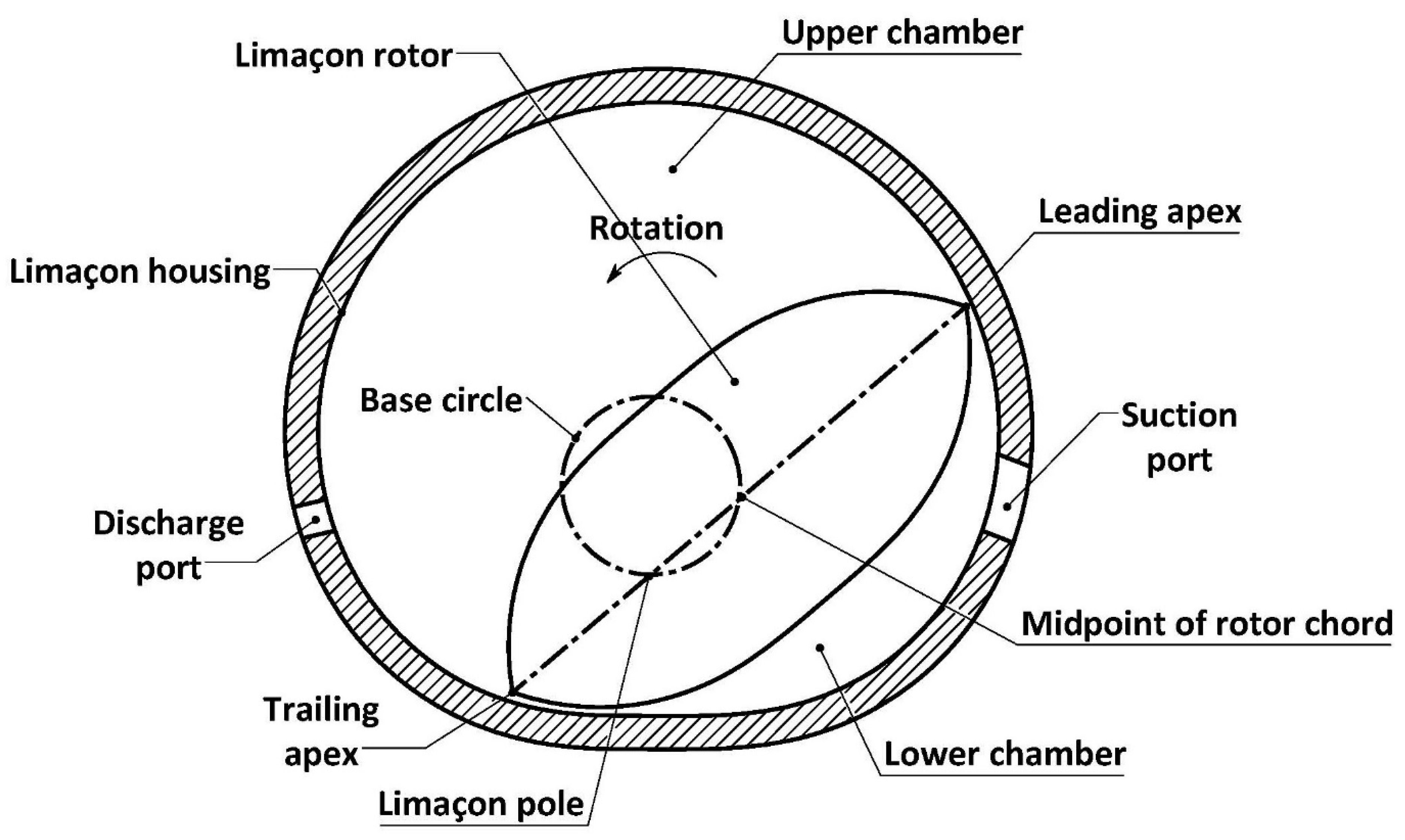
Over the years, positive displacement compressors have gained popularity in many industries. In the automobile industry, by way of example, reciprocating compressors are employed for tyre inflation and to actuate pneumatic brake systems; various positive displacement compressors are utilised in refrigeration systems to compress the refrigerant for the workings of the thermodynamic cycles featured in these systems. In recent market research, the global compressor market was reported at USD 39.9 billion in 2019, and it is expected to reach USD 48.5 billion by 2030, with the majority of the market share contributed by positive displacement compressors [9]. It is worth mentioning that compressed gas is regarded as one of the most expensive energy forms [10]. It was reported that nearly 20% of energy consumption in industries is attributed to producing compressed gas [11], whereas less than 30% of the compressed gas can be efficiently used [12]. In this context, the performance improvement of positive displacement compressors has become a popular research topic in both academia and industry. It is, therefore, not surprising that many emerging compressor technologies with significant energy-efficient potential have appeared in recent years. Table 2 lists the recently proposed designs of positive displacement compressors. By way of an example, Figure 2 shows a rotary compressor based on the limaçon technology as described in Sultan’s work [13]; this paper has discussed several patented limaçon drives that produce the same distinctive limaçon trajectory. In these drives, the line of symmetry of a lenticular rotor is made to slide at the limaçon pole as its midpoint stays attached to the circumference of the base circle. The trajectory of the apices of the rotor chord forms a curve called the limaçon of Pascal, which is utilised to construct the machine housing. The figure shows that the rotor geometrically separates the housing cavity into the upper and lower chambers. When the rotor rotates, the change in volumes of the two chambers will result in two compression strokes per revolution.
It is worth noting that review papers in the literature only focus on some specific subcategories or aspects of compressors. For example, Prasad [20] reviewed the past investigation of reciprocating compressors concerning heat transfer, while Stosic et al. [21] studied the achievements that have been made on the screw compressor. In this paper, the authors aim to review the earlier systematic and recent literature on various topics of positive displacement compressors. The structure of this paper is outlined as follows. Section 2 reviews the previous research on influencing elements of compressor performance, including leakage, heat transfer, friction and lubrication, valve and port characteristics, and capacity control methods. Section 3 discusses the current status of the application of machine learning algorithms in positive displacement compressors. Current challenges and opportunities for future research are proposed in Section 4. Finally, Section 5 presents the conclusions of this study.

2. Indicators of Compressor Performance

Compressor performance can be assessed by several indicators, such as volumetric and isentropic efficiency, heat transfer characteristics, and losses due to leakage and friction. The following sections of this paper provide detailed discussions of these indicators.

2.1. Basic Equations for Positive Displacement Compressors

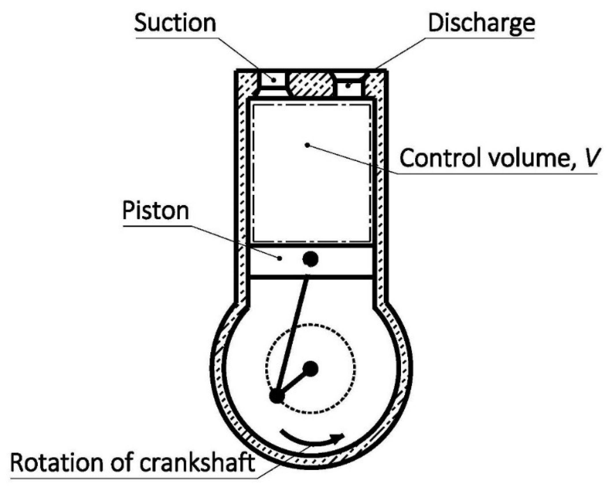
Figure 3 is employed here as an excellent example of positive displacement compressors where the working fluid is admitted into a compression chamber of volume, V , through a suction valve with the help of the vacuum created by the machine’s member, which controls the volume, V . The moving machine’s member can be, in this case, a reciprocating piston (shown in Figure 3); however, it can also be rotating components in other designs, as depicted in Figure 1.
Irrespective of the geometry of the specific positive displacement compressor under study, they all share the same constituents, which impact their volumetric and work performance. Figure 4 shows a theoretical pressure–volume (PV) diagram that characterises the thermodynamic states of the working fluid in a compression cycle. The compression stroke occurs from state 1 to state 2, during which the working fluid is compressed from suction pressure, P 1 , to the discharge pressure, P 2 . As the compressed fluid is discharged, the compression chamber’s volume decreases to V 3 (the clearance volume). Subsequently, the volume is slightly increased to V 4 due to the expansion of the fluid trapped in the clearance volume. The suction stroke takes place from state 4 to state 1, and the theoretical volume, V i , of the fresh charge, or the free air delivery (FAD), and the swept volume, V s , are expressed as follows,
V i = V 1 V 4
and
V s = V 1 V 3
The ratio between the volumes given by Equations (1) and (2) is the volumetric efficiency, which is expressed by the equation below,
η v = V i V s = V 1 V 4 V 1 V 3    
The volumetric efficiency is an important parameter to quantify the volumetric performance of positive displacement compressors. The measured volumetric efficiency values are often lower than the ideal theoretical values due to the effects of leakage and valve dynamics. Another performance index is compression efficiency, defined as the ratio of the theoretical and actual work needed per cycle. Depending on the theoretical process of choice, the compression efficiency can be expressed as follows,
η i s e n = W i s e n W a c t u a l ,     Isentropic   efficiency η p = W p W a c t u a l ,     Polytropic   efficiency η i s o = W i s o W a c t u a l ,     Isothermal   efficiency
where the theoretical work for each case can be calculated as follows [22],
W i s e n = γ P 1 V i γ 1 P 2 P 1 γ 1 γ   1 ,     Isentropic   work W p = n P 1 V i n 1 P 2 P 1 n 1 n   1 ,     Polytropic   work W i s o = P 1 V i ln P 2 P 1 ,     Isothermal   work
where γ is the ratio of specific heats and n is the polytropic index.
It is worth mentioning that the compression work, owing to the losses (e.g., friction), is always less than the mechanical work, W s , measured at the crankshaft. Therefore, the mechanical efficiency, η m , is used to quantify how efficiently mechanical work can be converted into compression work,
η m = W a c t u a l W s
In addition to the efficiency terms described above, the coefficient of performance (COP) is often used to indicate the performance of a vapour compression refrigeration system (VCR). The COP is defined as the ratio of the cooling or heating capacity, Q , to the energy required, W R , as,
C O P c o o l i n g / h e a t i n g = Q c o o l i n g / h e a t i n g W R
In a VCR system, the compressor consumes the most energy; therefore, Equation (7) can also be used to show the compressor performance of the VCR systems to a certain extent.
The performance indices mentioned above are affected by various factors. For example, internal leakages and gas superheating can result in a decrease in the volumetric efficiency. The following sections will review studies investigating the effect of influencing indicators on the performance of positive displacement compressors.

2.2. Leakage

Leakage is one of the leading indicators affecting the performance of positive displacement compressors. The clearances between the machine’s parts and compartments allow compressed gas to escape from the high-pressure chambers; thus reducing delivery and compromising performance. The published literature suggests that various methods have been proposed to analyse the leakage occurring in positive displacement compressors. The main difference between these methods is the assumptions made to characterise the leakage flow. The isentropic flow model is widely used. This model assumes the leakage flow to be isentropic and compressible, occurring through an orifice or a convergent nozzle. For example, Cho et al. [23] suggested these equations below to calculate the mass flow rate, m ˙ , of the leakage,
m ˙ = C A P u 2 γ γ 1 R T u P d P u 2 γ   P d P u γ + 1 γ ,     P d P u 2 γ + 1 γ γ 1 C A P u γ R T u 2 γ + 1 γ + 1 γ 1 ,     P d P u < 2 γ + 1 γ γ 1
where C is the discharge coefficient, A L is the flow area of the leakage, R is the ideal gas constant of the fluid, T and P are temperature and pressure, respectively, and the subscripts u and d denote the upstream and downstream of the leakage paths, respectively.
The results presented by Yuan et al. [24] suggest that the orifice assumption produces conservative estimates of leakage values in comparison to more accurate differential models, which take gas viscosity and inertia into account. The graphs featured in the work by Yuan et al. [24] indicate that a carefully selected discharge coefficient can bring the results of the orifice assumption close to the results of a more sophisticated and computationally costly model. Kim et al. [25] utilised computational fluid dynamics (CFD) to determine the flow coefficient with respect to the change in upstream pressure and the width of radial clearance. It was found that the discharge coefficient ranges from 0.17 to 0.85 for the radial clearance of 10 μ m to 60 μ m under an upstream pressure of 30 bar . Pereira and Deschamps [26] used various dimensionless parameters to illustrate the effect of working gas types, operating conditions, and geometric characteristics on the overall leakage. The results show that the model could accurately predict the radial and tangential leakages, with average errors of 2.4% and 7.9%, respectively. In a recent study, Lu et al. [27] formulated the internal leakage at the seal-housing gap of the novel limaçon compressor.
Another method is the Fanno flow model, which treats the leakage as an adiabatic flow by considering the fluid’s viscous effect over the path with a constant cross-sectional area. Yanagisawa and Shimizu [28,29] adopted this model to investigate leakage in a rolling piston compressor. The authors found that the eccentric assembly of the main bearing can minimise the effect of dynamic behaviours of bearings on the radial clearance, reducing the leakage flow considerably. Rodgers and Nieter [30] and Kang et al. [31] compared the Fanno flow model with the isentropic flow model and concluded that the Fanno flow model provides more realistic predictions than the isentropic nozzle model, especially with a larger clearance. Teh and Ooi [32] discovered that a shorter rotor-cylinder configuration could reduce the leakage flow and achieve a volumetric efficiency of more than 95%. However, a more extended configuration is usually preferable to minimise frictional loss. The authors suggested using the eccentric cylinder to balance the impacts on the performance caused by leakage and frictional losses. Silva and Deschamps [33] also analysed the leakage through the valve using the Fanno flow leakage model. It was found that the leakage flow through the discharge valve was more significant than the suction valve leakage. Additionally, the authors reported reductions of volumetric and isentropic efficiencies by 2.7% and 4.4% per 1 μ m increment of the valve clearance. Recently, Aw and Ooi [34] combined the Fanno flow model with CFD to determine the empirical correlations for the equivalent channel width for various factors, including pressure ratio and rotation angles. According to the results, one can conclude that the Fanno model can predict the leakage flow within a discrepancy of ±15%.
It is worth mentioning that both the isentropic and Fanno flow models consider compressible leakage. The work of Ferreira and Lilie [35] utilised a different method in which the leakage flow is assumed to be turbulent and incompressible. Predictions provided by this method agree well with experimental measurements in the small clearance regions, but the discrepancy gradually becomes more evident as the clearance increases. This might be attributed to the inertial force that this model neglects. The work of Ishii et al. [36] is another example that employs the incompressible leakage model; the results obtained from the incompressible flow model are more accurate than those of the model based on more complicated compressible formulations. Hence, the authors suggested that the incompressible model is adequate to analyse the leakage flow, while the compressible flow model is not necessarily useful. This contradicts the opinion proposed by Lohn and Pereira [37], who pointed out that the incompressible model cannot sufficiently describe the complexity of the leakage flow and generates more uncertainties.
Table 3 below summarises different leakage models in the literature.

2.3. Heat Transfer

Heat transfer describes a process in which heat is transferred from one object to another via three mechanisms: convection, conduction, and radiation. For positive displacement compressors, heat is generated during the compression process and directly affects the temperature of the working fluid and machine components. This leads to undesirable consequences that affect the machine’s performance as well as reliability. Thus, compressors are generally designed such that some of this heat is transferred to the surroundings via convection and conduction, which are the major mechanisms of heat transfer as the effect of radiation is relatively insignificant. In this section, the focus is drawn towards the effect of convection and conduction in positive displacement compressors.

2.3.1. Convection Heat Transfer

Convection is the heat transfer process that involves the flow of fluid and temperature gradients. Theoretically, the rate, Q ˙ c o v , of convective heat transfer can be calculated by the equation below,
Q ˙ c o v = h A Δ T
where A is the heat transfer area and Δ T is the temperature difference. The term h in Equation (9) is the convective heat transfer coefficient, and it is determined from the empirical Nusselt number, N u , as shown below,
h = N u k D h
and
N u = c R e a P r b  
where k is the thermal conductivity of the fluid, D h is the hydraulic diameter, R e is the Reynolds number, P r is the Prandtl number, and a , b , and c are the empirical constants.
Before the 1970s, the N u correlations were mainly developed for investigating heat transfer in internal combustion (IC) engines, e.g., Annand [38]. The work of Adair et al. [39] was among the first that proposed a Nusselt correlation for the reciprocating compressor. Later, Liu and Zhou [40] further developed the correlation by modifying the expression of swirl velocity, which also considers the effect of lubricating oil. These two correlations (Adair’s and Liu’s) have been compared in the work of Tan and Ooi [41], who investigated the heat transfer in the revolving-vane compressor. The authors modified the characteristic velocity to cater for the geometric characteristics of the machine, and the result shows that Liu’s correlation could produce relatively accurate predictions with a maximum error of less than 2%.
In another study of heat transfer in reciprocating compressors, Hsieh and Wu [42] pointed out that the fluid velocity changes rapidly at the beginning of the discharge process, and consequently, the average piston velocity is inadequate to represent the fluid velocity inside the cylinder. As such, they suggested the normalised viscosity term to replace the Prandtl number and introduced an additional Reynolds number. Based on the experiment, a set of correlations was determined for different processes of the working cycle, and the comparison between the numerical results obtained by the proposed correlations agree well with the experimental data. However, as reported by the authors, this correlation is unsuitable for dealing with phase-changing cases. Disconzi et al. [43] pointed out that the recirculating flow caused by valve dynamics during the suction and discharge process strongly affects the effective heat transfer area. The authors suggested relating the characteristic velocity of the Reynolds number to the mass flow rate through valves, proposing different correlations specifically for each process during the cycle.
Ooi and Zhu [44] revealed that existing correlations applied for reciprocating compressors are inadequate for the scroll compressor due to the geometry variation and flow directions. The authors presented a 2D model that considered the effect of geometry on flow characteristics and compared the proposed model and earlier models. The result showed that predictions of the amount of heat transfer calculated by the proposed model were significantly higher, mainly because of recirculating flow and the geometry deformation on the fluid velocity in the late compression period. Another study on the scroll compressor was conducted by Jang and Jeong [45], who considered the effect of orbiting scroll oscillation on heat transfer occurring in the scroll wrap. Based on the experimental results, the authors proposed a modified Nusselt correlation to provide more accurate predictions of the discharge temperature.
Recently, Rak and Pietrowicz [46] proposed a correlation for scroll compressors by curve-fitting the data of the CFD simulations. It was found that this correlation could bring the error down to less than 15% compared to results from the 2D numerical model. Table 4 below shows the correlations proposed in different literature for positive displacement compressors.

2.3.2. Conduction Heat Transfer

Conduction, which takes place between the adjacent solid components, is another primary mechanism of heat transfer in positive displacement compressors. Proper conduction analysis can improve the machine’s reliability as it provides insight into compressor components’ temperature distribution and thermal loading.
Padhy and Dwivedi [47] proposed a lumped model in which the rolling piston compressor was separated into 22 elements. The results show good agreement between the estimates and the measured data; it has been found that the most significant difference was 3.37 °C for the temperature of the fluid inside the cylinder. This lumped model was later adopted for the reciprocating compressor by Ooi [48], who reported the discrepancy between predictions and measures below 10%. Another application of the lumped method was detailed by Sanvezzo and Deschamps [49]; the authors investigated conductive heat transfer in the reciprocating compressor. The numerical results reasonably agree with the experimental data, flagging a maximum discrepancy of only 14.4 °C (located on the cylinder surface). Dutra and Deschamps [50] conducted an experiment to investigate the conductive heat transfer in a reciprocating compressor. Temperatures of eleven locations were acquired under three operating conditions, and the thermal conductance values at each tested location were determined accordingly. Patil et al. [51] discovered that the rate of heat transfer increased as the result of fast compression, whereas the overall heat transfer coefficient decreased at the beginning of the compression stroke and eventually stabilised between 8 and 12 W / m 2 K . Additionally, an isothermal efficiency of 84–86% was reported at a compression ratio of 2.05–2.35. In another study, Stosic [52] utilised the quasi-one-dimensional model to obtain the fluid temperature and calculate the heat transfer by convection and conduction. The author reported that the result agreed with records of the visualisation experiment, and it was found that the temperature was linearly distributed along the rotor axis and the maximum temperature of the rotor could be reduced from 700 K to 350 K, thus improving the machine reliability at high pressure ratios.

2.4. Friction and Lubrication

In positive displacement compressors, undesirable friction is primarily responsible for decreased mechanical efficiency. More importantly, severe wear and component failure generally occur at contact regions between moving components, deteriorating machine durability.
The available literature shows that the reduction of friction loss in positive displacement compressors is mainly achieved by two approaches. The first method is through the geometric optimisation of the machine. Yanagisawa and Shimizu [53] investigated friction losses of the rolling piston compressor. They concluded that the vane-tip friction is mainly affected by the absolute sliding velocity of the vane tip, whereas the tangential force strongly influences the vane-side friction. Additionally, the total frictional loss is more sensitive to the change in the rotor radius rather than the cylinder length. Later, Ooi [54] found that a narrower but taller cylinder could reduce the friction loss in the rolling piston compressor. This leads to an increase in the mechanical efficiency up to 14%. Teh and Ooi [55] then introduced a revolving-vane mechanism in which the rotor and the cylinder rotate concentrically. Compared to the traditional rolling piston compressor, the proposed design minimises relative motions between the contacting surfaces in the cylinder, and consequently, the total friction loss was reduced by 19.7%, which lifts the mechanical efficiency to 94.1%.
Liu et al. [56] developed an optimisation procedure to reduce friction losses among bearing components of the scroll compressor, including the thrust bearing, the crank bearing, and the upper and lower bearings. The authors found that friction loss could be reduced from 11.4% to 38.1% by introducing smaller diameters to the four bearings. Yang et al. [57] reported that friction losses at the bearings of the reciprocating compressor decreased with the stroke-to-bore ratio, whereas the friction between the piston and cylinder wall exhibited an opposite trend due to the increase in piston mean velocity. In sliding vane compressors, Bianchi and Cipollone [58] discovered that a lighter vane blade and a slower operating speed could significantly reduce friction losses. Recently, Gu et al. [59] proposed a new variant of the sliding vane compressor, which features a rotating cylinder. Under the same working conditions, it has been found that the proposed design could reduce friction losses by up to 10% as compared to the conventional design.
Another method to reduce friction losses is to apply lubricants. Kim and Lancey [60] modelled the lubrication system of a rolling piston compressor to predict the lubricating oil flow rate. Compared with the measured data, predicted values obtained by the model presented acceptable accuracy, with a difference of 5.8%. Afshari et al. [61] investigated the effect of the oil viscosity on the energy consumption of a reciprocating compressor used for air-water heat pumps. Wu et al. [62] proposed a comprehensive network model to describe lubricating oil circulation throughout the screw compressor. Their experiment found that the machine’s overall performance could be improved by injecting low-temperature lubricating oil from the discharge end bearing to the working chamber. In recent research conducted by Ozsipahi et al. [63], the lubrication system of a compact inverter reciprocating compressor was numerically modelled by using two CFD methods, namely the sliding mesh and the moving reference frame.
Apart from the typical role in reducing friction loss, lubricants can address losses caused by other factors, such as leakage and gas superheating. Valenti et al. [64] found that the lubricating oil film (with a size of 100 μ m ) could effectively reduce the fluid temperature to as low as 60 °C, allowing the compression work of a mid-size vane compressor to decrease by 23–28%. In another study, Pizarro-Recabarren and Barbosa [65] reported that the lubricating oil could slightly increase the cooling capacity and indicated COP by 2.3% and 9%, respectively.

2.5. Valve Dynamic and Port Characteristics

The valve is an essential component of positive displacement compressors in controlling the fluid flow during the suction and discharge stages. A suction valve is used to admit fresh charge, while a discharge valve prevents the backflowing of compressed fluid.
Reciprocating compressors are generally equipped with both suction and discharge valves and studies on the valve dynamic can be sought in a large body of literature. A typical example is found in the work by Nagata et al. [66], who analysed the effect of the compressor operating speed on the suction valve. The authors found that low speeds could result in severe valve vibration over the suction port, causing the volumetric efficiency to fluctuate periodically. As the speed increases, the viscous effect of the lubricant on the valve could be reduced, which increases the maximum displacement. By conducting an experimental study on the trans-critical CO2 compressor, Ma et al. [67] suggested that a reasonably low discharge pressure and a smaller size of valve lift are preferable for valve life due to lower stress from the rebound process. The results of the investigation of the effect of various factors on the impact load acting on the ring valve done by Wang et al. [68] have suggested that the valve inclination becomes more severe during the closing of the discharge valve, and the inclining angle of the discharge valve becomes unpredictable when the pressure ratio exceeds 2.55. Additionally, the impact velocity of the valve was mainly affected by the variation of the piston velocity and the volume of the compression chamber. On this critical topic of valve failure, Mu et al. [69] have proposed a dynamic model to analyse the factor that causes such failures. The proposed model considered the relationship between the valve displacement and various factors, including the effective length, the elastic force, the mass of the valve reed, and the viscous stiction. In a recent study, Egger et al. [70] introduced a mechanical support mechanism to the conventional valve. They reported that the proposed design could increase the cooling capacity by 22% and considerably reduce the impact stress during the suction process, while the improvement of COP was quite limited due to the additional friction losses caused by the support mechanism.
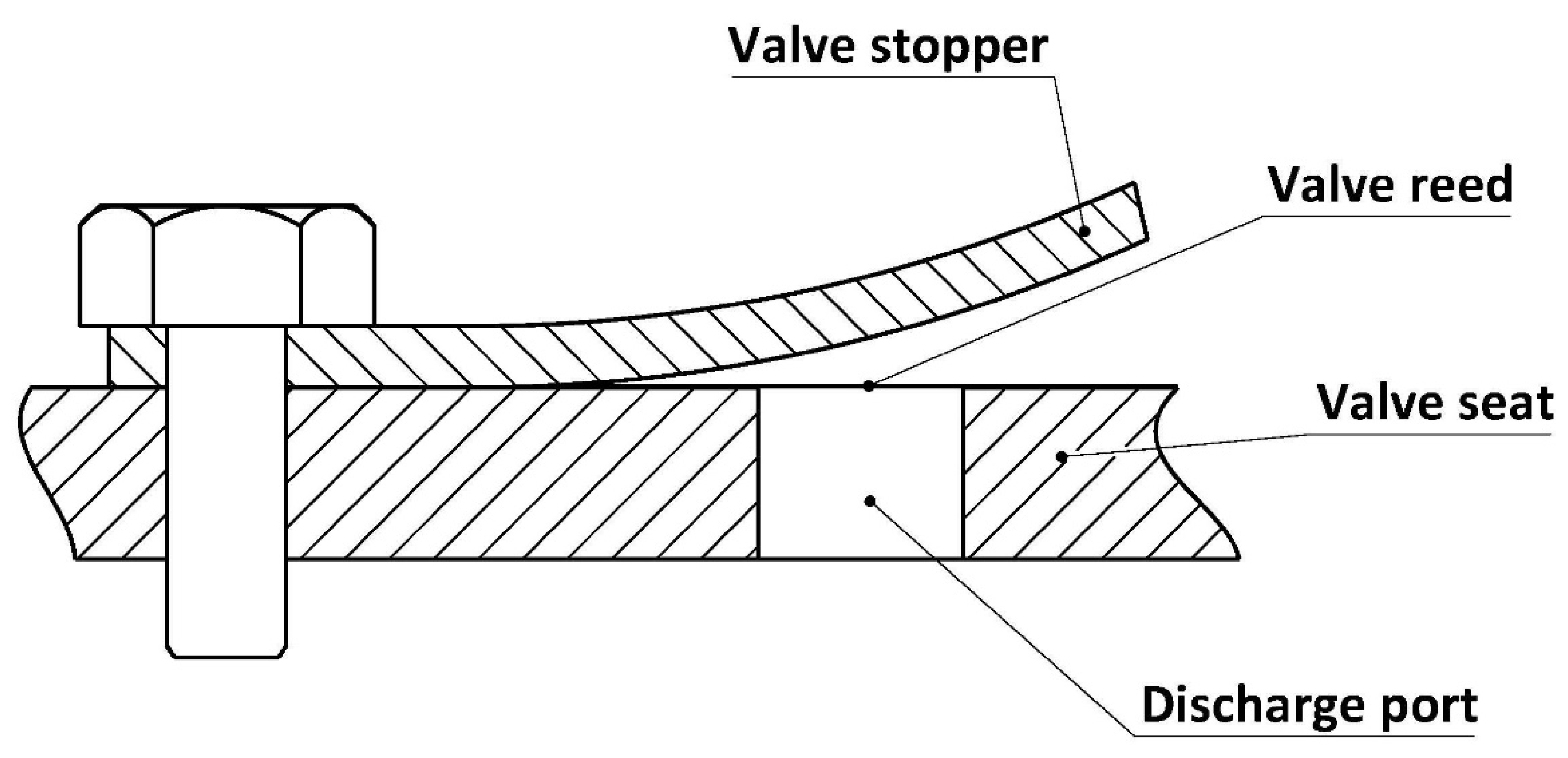
In rotary compressors, the suction valve is not necessarily required as the suction and discharge ports are physically separated by the rotor. In contrast, the discharge valve is essential in ensuring the fluid is delivered at the designated pressure while avoiding the high-pressure backflow. Generally, the reed-type valve, as shown in Figure 5, is commonly used in various rotary compressors. Huang and Xie [71] presented a dynamic analysis to investigate the retainer’s influence on the valve’s reliability. The simulation results show that the pressure pulsation became more severe during the discharge process when the size of the retainer was reduced. Teh et al. [72] modelled a rotating valve employed in the revolving-vane compressor. Compared to the conventional design, the rotating valve was found to possess better reliability due to the softening effect of the centrifugal force. However, the author suggested that the dimensions of the valve should be chosen following the operating speed to avoid valve loss due to centrifugal overloading and resonance. Yu et al. [73] applied the fluid–structure interaction (FSI) to analyse the effect of the torsional movement. They reported that the maximum impact stress was found to increase in the torsional direction, and the level of the torsional movement was significantly affected by the geometry of the discharge port and the mounting method of the valve reed. Later, Min et al. [74] proposed an empirical correlation of the discharge coefficient to calculate the effective area. This correlation was derived based on the CFD simulation that considers the influence of geometric parameters, including the valve lift, the valve size, and the port dimensions. Compared to the experimental result, the proposed correlation was found to predict cooling capacity and input power with an error band of 10%.
During the suction and discharge processes, the mass flow rate of the fluid is not only affected by the dynamic behaviour of the valve, but also by the port characteristics, including position, geometry, and size. Kim et al. [75] studied the performance of the twin rotary compressor, and their result showed that the adiabatic efficiency could be increased when either the port diameter or porting angle were increased. Mujic et al. [76] found that the shape and size of the discharge port are the dominant parameters that affect the gas pulsation occurring in the screw compressor. In a study of the limaçon positive displacement machine, Sultan and Schaller [77] utilised the stochastic optimisation technique to find the port geometry that can produce the best performance for given machine dimensions. Lim et al. [78] reported that the increase in the size of the port led to a higher suction loss but a lower discharge loss. In another study, Zhao et al. [79] proposed a new design for the discharge port to alleviate the severe pressure difference between the up and down-side chambers of the scroll compressor. The results showed that applying the proposed discharge port could achieve a 2.4% improvement in the isentropic efficiency and a 50% reduction in pressure difference. Recently, Gu et al. [80] analysed the influence of the port configuration employed in their proposed sliding vane compressor with a rotating cylinder. The authors concluded that the machine performance was more sensitive to the variation of the coverage angle.

2.6. Capacity Control

Capacity control is the method that assists the compressor in adjusting the machine capacity as per the working load on demand. In the compressor system, capacity control methods can ensure the machine operates efficiently and protect the system from failure. In the open literature, stepless control and variable-speed control are the two commonly used methods in positive displacement compressors.
The principle of stepless control is to delay the closing time of the suction valve via the supply of an external force (usually hydraulic force), allowing excess fluid to escape from the working chamber [81]. Stepless control was proposed by the work of Tuymer [82], and it has been mainly used in reciprocating compressors. In the past decade, the research interest in stepless control has focused on theoretical modelling and performance analysis [81,83,84], dynamics of the suction valve [85,86,87], and the optimisation of the actuator [88,89,90].
Another frequently used capacity control method is speed control, in which the operating speed is regulated by a variable-speed drive in response to the variation of the working load. In practice, speed control is widely employed for domestic refrigeration and air-conditioning systems [91]. Tassou and Qureshi [92] assessed the performance of three compressors with speed control. The results show that the volumetric efficiency of all tested compressors increases with speed, while the isentropic efficiency exhibits an opposite trend. Additionally, the authors also reported that speed control provides energy savings of up to 9.6%, 23.7%, and 9.8% for rotary, open-type, and semi-hermetic reciprocating compressors, respectively. In another study, Aprea et al. [93] found that an average energy saving of 20% could be achieved if speed capacity control is introduced to the scroll compressor. Wang et al. [94] compared the variable-speed method with sliding valve control, and it was noticed that the variable-speed control could provide an adiabatic efficiency of 72.8% at a 25% load condition, which is better than the 42.5% obtained from the sliding valve mechanism.
Capacity control of fluid-compression systems can also be realised in some other ways. Bypass/recycle is the simplest way to adjust the compressor capacity, which directs the redundant fluid in the discharge side back into the suction side via a bypass pipe [95]. However, the compression work of the bypassed fluid is wasted, making this method an inefficient form of capacity control. The work by Jeong et al. [96] reported that the compressor performance with speed control is 5 times as good as that with gas bypass at part load. However, the work by Wang et al. [97] pointed out that the COP and energy efficiency of the scroll compressor could be improved up to 34% and 42%, respectively, if the gas was bypassed at the suction instead of after compression stroke.
Other capacity control methods include clearance pocket and suction throttling [98,99,100,101], but the literature available on these topics is limited. Table 5 presents a comparison of different capacity control methods.

3. Recent Innovative Modelling in Compressor Research

In the design phase, mathematical modelling is the most practical and economical method to simulate the thermodynamic processes implemented by the machine and predict the performance of the system. The published literature shows that most of the mathematical models are derived by using physical and thermodynamic laws together with the description of machine dimensions and geometries. For example, Ooi and Wong [102] proposed a mathematical model of the rolling piston compressor that considers geometric, thermodynamic, dynamics, and frictional effects.
However, the process executed by the compressor is rather intricate, causing the mathematical relationship underlying such a process to be not readily obtainable [103]. As such, the conventional modelling method is usually insufficient to describe the workings of the compressor under the actual condition. Recently, there has been a trend of using machine learning methods for mathematically impractical applications. One remarkable benefit is that such a method is trained by a small number of actual measurements to explore the hidden function that relates inputs and outputs, meaning the mathematical relationship between parameters is unnecessary. This section will provide an overview of several machine learning methods that have been applied to the modelling and optimisation process of positive displacement compressors.

3.1. Artificial Neural Network

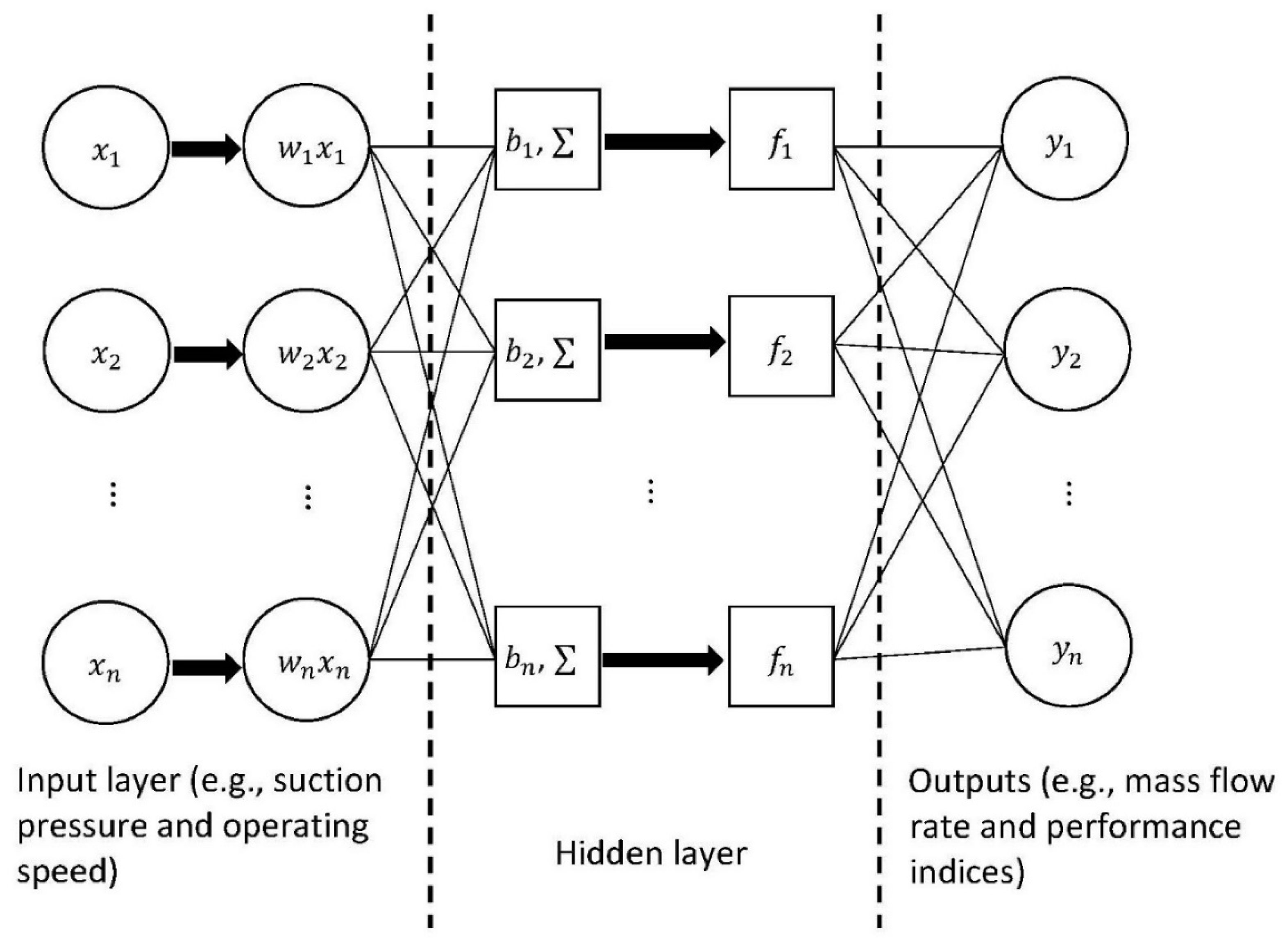
Artificial neural network (ANN) is a method inspired by biological neural networks to solve complex problems in a variety of disciplines [104]. A typical structure of ANN has three layers, namely input, hidden (can be multiple), and output layers. In practice, each input data, x , is multiplied by a weighting factor, w , and then connected to the output via the hidden layer, which contains an added bias, b ; the summation function, ; and the activation function, f. Figure 6 depicts the schematic diagram of the ANN workflow.
In positive displacement compressors, ANN is a popular method for mathematical modelling and performance prediction. Sanaye et al. [105] modelled the rotary vane compressor by using the ANN method. The predictions from the ANN model agreed well with the experimental data, showing the largest mean relative error (MREs) of 7.36%. Namdeo et al. [106] applied ANN to analyse the leakage through the valve so that the valve failure can be detected at an early stage. In a later study, Belman-Flores et al. [107] further demonstrated the accuracy of the ANN model and compared it with the physical model in terms of modelling a reciprocating compressor. Tian et al. [108] proposed a hybrid model, which combines partial least squares (PLS) regression with ANN, to predict the thermodynamic performance of the scroll compressor. Compared to the model using only ANN or PLS, the hybrid model produced relatively accurate results, in which the largest MREs was 1.96% and the correlation coefficients ranged from 0.9703 to 0.9999. In another study, Zendehboudi et al. [109] compared the reliability of two modelling methods, i.e., ANN and adaptive neuro-fuzzy inference system (ANFIS), in modelling a scroll compressor that has a vapour injection mechanism. The authors found that both modelling techniques showed comparable performance in terms of predictions of the discharge flow rate and power consumption, with the largest difference of less than 0.7%.

3.2. Genetic Algorithm Optimisation

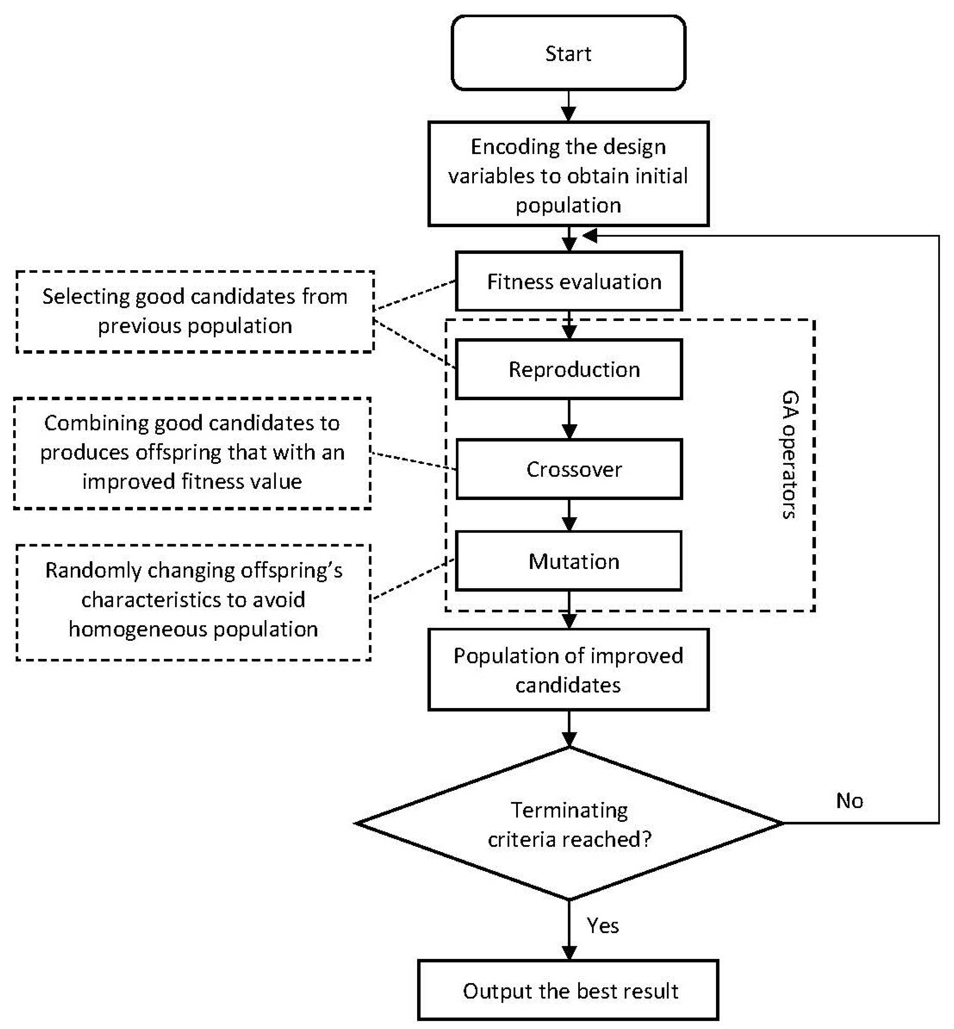
Genetic algorithm (GA) is another machine learning method used in the optimisation of many engineering problems. It is inspired by the principle of natural selection and evolution to find design solutions from a large search space based on fitness/objective values [110]. A classic GA is comprised of five phases, including encoding, fitness/objective evaluation, reproduction, crossover, and mutation. Figure 7 presents a detailed process of GA.
The work of Huang and Tsay [111] is an example that used the GA method to optimise the mechanical efficiency of the sliding vane compressor. Chen and Ooi [112] developed an optimisation procedure for the coupled vane compressor based on the non-dominated sorting genetic algorithm II (NSGA-II). From the optimisation result, the authors found that a larger working chamber with a smaller rotor could improve the compressor performance with respect to the same cylinder size. The NSGA-II was also adopted by studies of reciprocating compressors aimed at optimising the actuator for the stepless control system [88,89]. In a recent study, Silva and Dutra [113] applied GA to optimise the piston trajectory of the reciprocating compressor. The authors reported that the optimum piston trajectory could increase the thermodynamic efficiency from 88.3% to 92.1% and the volumetric efficiency from 70.9% to 72%. In addition, the proposed optimum design was found to be more efficient and less affected by the pressure ratio under working conditions other than the baseline.

3.3. Other Methods

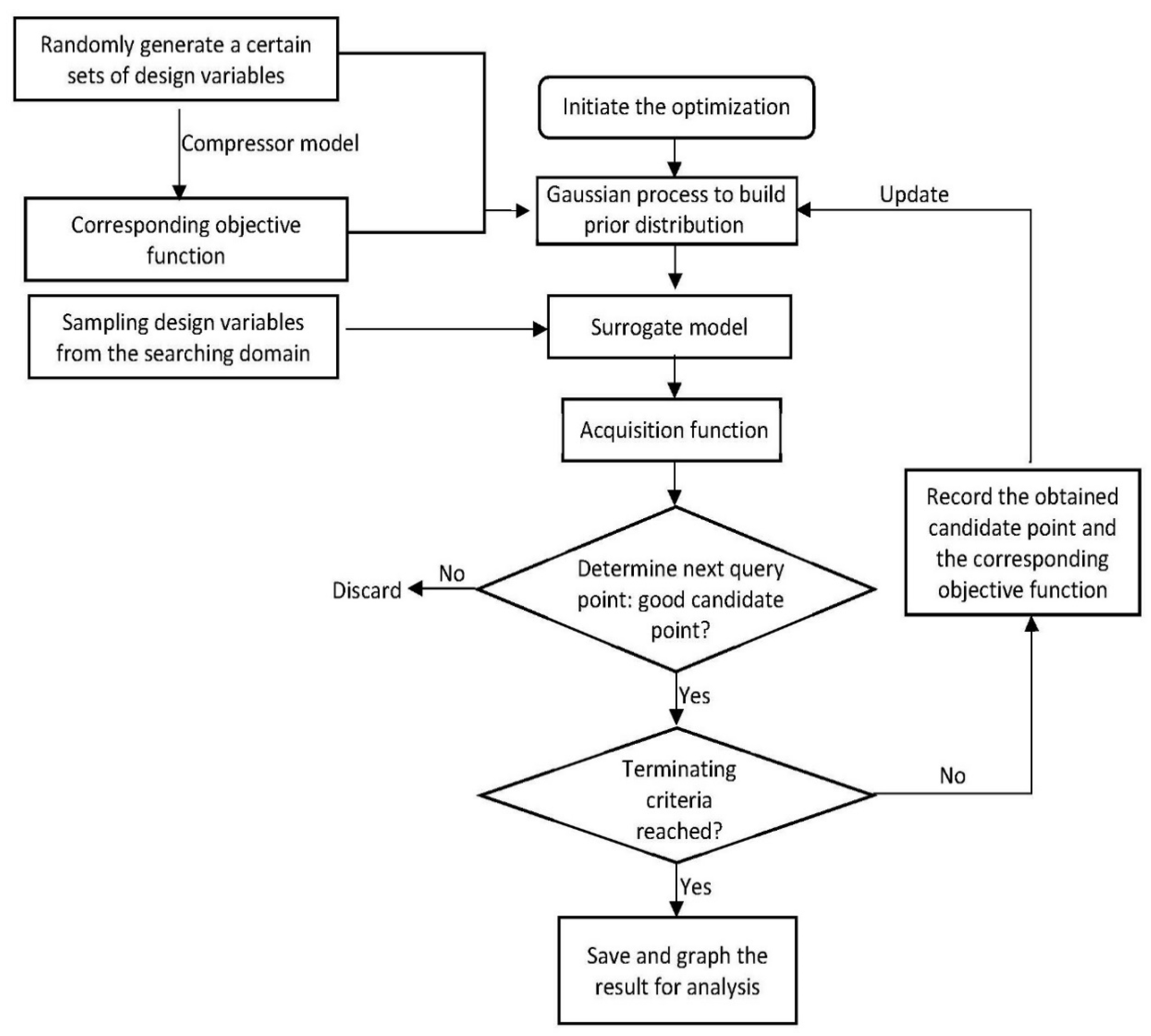
There are some other machine learning methods applied in the modelling and optimisation of positive displacement compressors, albeit to a limited level. Lu et al. [114,115] used the Bayesian optimisation method to optimise the port geometries of the limaçon rotary compressor. According to the results, the authors discovered that most of the obtained outcomes fall within the desired region, and the average isentropic and volumetric efficiencies obtained from the optimisation were 93.81% and 83.62%, respectively. In addition, the authors also reported that the obtained optimum design exhibits a certain level of robustness when the operating condition fluctuated within a small percentage around that used in the optimisation. Figure 8 shows the process of the Bayesian optimisation method applied in positive displacement compressors.
Sultan and Kalim [116] presented a two-level hybrid optimisation, which incorporates the simultaneous perturbation stochastic approximation (SPSA), to find the best piston trajectory of the reciprocating compressor driven by the geared five-bar mechanism. Later, Phung and Sultan [117] also employed the SPSA method to optimise the dimensions of the limaçon positive displacement machine for given operating conditions. Qi et al. [118] employed principal component analysis (PCA) to denoise the large-scale data, and the denoised data were then used by the support vector machine (SVM) classifier to obtain the sparse coefficient for the fault-diagnosis model. The authors reported that the proposed model is robust to the change in working conditions, with an accuracy rate of 80% for detecting potential faults. Recently, Lu et al. [119] adopted PCA to optimise the heat transfer and torque patterns to improve the reliability of the reciprocating compressor. Table 6 summarises the application of various machine learning methods in positive displacement compressors.

4. Challenges and Opportunities for Future Studies

Although numerous research works have been dedicated to various aspects of positive displacement compressors, further investigations are needed to address some key issues. For example, the compressor performance and working characteristics reported in the literature may be insufficient to guide the selection process, as most studies were conducted under specific working conditions. More experimental studies are needed to provide more detailed information on positive displacement compressors, especially the new technologies. Moreover, it is worth mentioning here that compressor performance maps are useful tools to guide the machine selection process as per the demand of the application. However, performance mapping of positive displacement compressors was rarely discussed in the available literature [120], and more importantly, the current standard [121] of the mapping approach applies only to a limited range of applications. Therefore, it is also recommended that more research efforts should be conducted on this topic.
The application of lubricating oil has many positive effects on machine performance [122]. However, the extreme condition (i.e., high temperature and pressure) at the compressor discharge and the presence of the fluid–oil mixture significantly affects the viscosity of the oil and deteriorates the lubricating performance. Hence, further study on lubrication systems is required. In fact, one solution to such an issue is by applying materials, such as nanoparticle additives, that have extreme condition functionality [123], this may need interdisciplinary collaborations between mechanical and material engineering.
Although research interest in the two-phase flow has increased significantly, the discontinuity of properties of the two-phase flow is still a challenging issue and further development of two-phase flow modelling is necessary. With the aid of advanced simulation resources, compressor models based on CFD have become more accessible, offering more insights into complicated phenomena such as heat transfer. However, the difficulties in solving problems that require multiphysics modelling still exist, and the balance between model accuracy and computational cost also remains a challenge.
Machine learning methods have become increasingly popular in the modelling and optimisation of positive displacement compressors. The major benefit of using machine learning methods is that the mathematical relationship between parameters is not necessarily required. Therefore, it could be expected that future work on modelling and optimisation will be more effective if machine learning methods are widely adopted.
Exergy and thermoeconomic analysis is an effective method to identify irreversibility and the associated costs in the system. Researchers, especially from the industry, should pay more attention to such method, as it can provide useful information about potential improvements and capital savings for the compressor and its system.
Waste heat recovery is a promising method to recycle the thermal energy produced in fluid compression. One noticeable advantage of this method is the improvement in energy utilisation due to the recovery of waste heat. However, the current challenge with this method is the cost and technology to be utilised to recover low-grade waste heat, which makes this method less attractive to small-scale applications, such as domestic refrigeration. Therefore, future research to address this issue would be beneficial for improving energy efficiency and sustainability of compressor systems.

5. Conclusions

Due to their essential role in many engineering systems, positive displacement compressors have received particular attention from the research sector. Many studies have been dedicated to better understanding the intricate workings of the compressor and bringing about improvements in machine performance. This paper presents a review of the published literature available on different topics of positive displacement compressors, including modelling of internal leakage and heat transfer, methods and design improvements to reduce friction, the effect of valve dynamics and port geometry, and capacity control strategies.
Machine learning methods have been demonstrated to be accurate and computationally cost-effective in solving complex problems. In positive displacement compressors, ANN is one of the most used machine learning methods to model the operation and predict the machine’s performance. In the past decade, other machine learning techniques, such as Bayesian optimisation, have been adopted in the design and optimisation phase, albeit to a limited level.
As research and development progresses, the performance of existing compressor technologies has been improved, and many innovative designs with significant potential for further performance improvements have been conceptualised and even commercialised. However, more studies are still needed for the current challenging issues; these are directions of research on positive displacement compressors in the future.

Funding

This research was founded by Findlay Engineering Pty Ltd. under the Federation University Australia Research Project (Project No. G2037).

Conflicts of Interest

The authors declare no conflict of interest.

Nomenclature

A Heat transfer area
AL Flow area of leakage
ANN Artificial neural network
C Discharge coefficient
CFD Computational fluid dynamics
COP Coefficient of performance
Dc Diameter of curvature
Dh Hydraulic diameter
FAD Free air delivery
GA Genetic algorithm
h Heat transfer coefficient
k Thermal conductivity
n Polytropic index
ηv Volumetric efficiency
ηisen Isentropic efficiency
ηp Polytropic efficiency
ηiso Isothermal efficiency
ηm Mechanical efficiency
m ˙ Mass flow rate
Wisen Isentropic work
Wp Polytropic work
Wiso Isothermal work
Ws Mechanical work
WR Work required
γ Ratio of specific heats
Q Heating capacity
R Ideal gas constant
St Strouhal number
SPSA Simultaneous perturbation stochastic approximation
SVM Support vector machine
T Temperature
ΔT Temperature difference
P Pressure
PCA Principal component analysis
PLS Partial least squares
Re Reynolds number
Pr Prandtl number
Nu Nusselt number
V Compression chamber volume
Vi Theoretical volume
Vs Swept volume

References

  1. Stouffs, P.; Tazerout, M.; Wauters, P. Thermodynamic analysis of reciprocating compressors. Int. J. Therm. Sci. 2001, 40, 52–66. [Google Scholar] [CrossRef]
  2. Sultan, I.A.; Phung, T.H. (Eds.) Positive Displacement Machines: Modern Design Innovations and Tools; Academic Press: Cambridge, MA, USA, 2019. [Google Scholar]
  3. Spark, I.J.; Lu, K. The orbital displacer: Implications and applications. In Positive Displacement Machines; Sultan, I.A., Phung, T.H., Eds.; Academic Press: Cambridge, MA, USA, 2019; pp. 3–34. [Google Scholar]
  4. Li, J.; Jia, X.; Wu, Z.; Peng, X. The cavity profile of a diaphragm compressor for a hydrogen refueling station. Int. J. Hydrogen Energy 2014, 39, 3926–3935. [Google Scholar] [CrossRef]
  5. Liang, K. A review of linear compressors for refrigeration. Int. J. Refrig. 2017, 84, 253–273. [Google Scholar] [CrossRef]
  6. Yanagisawa, T.; Shimizu, T.; Chu, I.; Ishijima, K. Motion analysis of rolling piston in rotary compressor. In Proceedings of the International Compressor Engineering Conference, West Lafayette, IN, USA, 21–23 July 1982; Purdue e-Pubs: West Lafayette, IN, USA, 1982. [Google Scholar]
  7. Stosic, N.; Smith, I.K.; Kovacevic, A. Numerical and experimental research in heat transfer to screw compressor rotors. In Proceedings of the ASME/JSME Thermal Engineering Joint Conference, Honolulu, HI, USA, 13–17 March 2011; Volume 38921, p. T20050. [Google Scholar]
  8. Chen, Y.; Halm, N.P.; Groll, E.A.; Braun, J.E. Mathematical modeling of scroll compressors—Part I: Compression process modeling. Int. J. Refrig. 2002, 25, 731–750. [Google Scholar] [CrossRef]
  9. Prescient & Strategic Intelligence. Compressor Market Research Report (2020–2030). 2020. Available online: https://www.psmarketresearch.com/market-analysis/compressor-market (accessed on 10 July 2021).
  10. Silva, W.L.V.; Souza, L.C.O.; Bortolaia, L.A.; Paula, M.R.D.; Leal, E.M. Study of the electricity consumption reduction of a compressed air system: The case of a steelmaking company. REM-Int. Eng. J. 2017, 70, 421–428. [Google Scholar] [CrossRef]
  11. Vittorini, D.; Cipollone, R. Energy saving potential in existing industrial compressors. Energy 2016, 102, 502–515. [Google Scholar] [CrossRef]
  12. Saidur, R.; Rahim, N.A.; Hasanuzzaman, M. A review on compressed-air energy use and energy savings. Renew. Sustain. Energy Rev. 2010, 14, 1135–1153. [Google Scholar] [CrossRef]
  13. Sultan, I.A. The limaçon of Pascal: Mechanical generation and utilization for fluid processing. Proc. Inst. Mech. Eng. Part C J. Mech. Eng. Sci. 2005, 219, 813–822. [Google Scholar] [CrossRef]
  14. Heidari, M.; Mortazavi, M.; Rufer, A. Design, modeling and experimental validation of a novel finned reciprocating compressor for Isothermal Compressed Air Energy Storage applications. Energy 2017, 140, 1252–1266. [Google Scholar] [CrossRef]
  15. Hu, Y.S.; Wei, H.J.; Xu, J.; Du, Z.C.; Yang, S.; Ren, L.P. The Theoretical and Experimental Research of a Novel Rotary Cylinder Compressor. In IOP Conference Series: Materials Science and Engineering, Proceedings of the International Conference on Compressors and Their Systems, City, University of London, 9–11 September 2019; IOP Publishing: Bristol, UK, 2019; Volume 604, Number 1; p. 012073. [Google Scholar]
  16. Shin, M.; Na, S.; Lee, J.; Min, B.; Choi, G. Model analysis of a novel compressor with a dual chamber for high-efficiency systems. Appl. Therm. Eng. 2019, 158, 113717. [Google Scholar] [CrossRef]
  17. Shakya, P.; Ooi, K.T. Introduction to Coupled Vane compressor: Mathematical modelling with validation. Int. J. Refrig. 2020, 117, 23–32. [Google Scholar] [CrossRef]
  18. Gao, X.; Liu, Y. Design, modeling and characteristics research of a novel self-air-cooling reciprocating compressor. Int. J. Refrig. 2021, 128, 62–70. [Google Scholar] [CrossRef]
  19. Lu, K.; Sultan, I.A.; Phung, T.H. Mathematical modeling and parametric study of the limaçon rotary compressor. Int. J. Refrig. 2021, 134, 219–231. [Google Scholar] [CrossRef]
  20. Prasad, B.S. Heat Transfer in Reciprocating Compressors: A Review. In Proceedings of the ASME International Mechanical Engineering Congress and Exposition, Anaheim, CA, USA, 15–20 November 1998; American Society of Mechanical Engineers: New York, NY, USA, 1998; Volume 15991, pp. 361–365. [Google Scholar]
  21. Stosic, N.; Smith, I.K.; Kovacevic, A.; Mujic, E. Review of mathematical models in performance calculation of screw compressors. Int. J. Fluid Mach. Syst. 2011, 4, 271–288. [Google Scholar] [CrossRef]
  22. Ueno, K.; Bye, R.E.; Hunter, K.S. Compressor Efficiency Definitions. 2003. Available online: http://vairex.com/resources/VAIREX_Compressor_Efficiency_Def_12May03.pdf (accessed on 17 August 2023).
  23. Cho, N.K.; Youn, Y.; Lee, B.C.; Min, M.K. The characteristics of tangential leakage in scroll compressors for air-conditioners. In Proceedings of the International Compressor Engineering Conference, West Lafayette, IN, USA, 25–28 July 2000; Purdue e-Pubs: West Lafayette, IN, USA, 2000. [Google Scholar]
  24. Yuan, X.; Chen, Z.; Fan, Z. Calculating model and experimental investigation of gas leakage. In Proceedings of the International Compressor Engineering Conference, West Lafayette, IN, USA, 14–17 July 1992; Purdue e-Pubs: West Lafayette, IN, USA, 1992. [Google Scholar]
  25. Kim, G.; Min, B.; Na, S.; Choi, G.; Kim, D. Estimation of leakage through radial clearance during compression process of a rolling piston rotary compressor. J. Mech. Sci. Technol. 2017, 31, 6033–6040. [Google Scholar] [CrossRef]
  26. Pereira, E.L.; Deschamps, C.J. Numerical analysis and correlations for radial and tangential leakage of gas in scroll compressors. Int. J. Refrig. 2020, 110, 239–247. [Google Scholar] [CrossRef]
  27. Lu, K.; Sultan, I.A.; Phung, T.H. A comparative study of two embodiments of the limaçon rotary compressor based on theoretical modelling of apex seal dynamics and leakage. Int. J. Refrig. 2023, 145, 467–480. [Google Scholar] [CrossRef]
  28. Yanagisawa, T.; Shimizu, T. Leakage losses with a rolling piston type rotary compressor. I. Radical clearance on the rolling piston. Int. J. Refrig. 1985, 8, 75–84. [Google Scholar] [CrossRef]
  29. Yanagisawa, T.; Shimizu, T. Leakage losses with a rolling piston type rotary compressor. II. Leakage losses through clearances on rolling piston faces. Int. J. Refrig. 1985, 8, 152–158. [Google Scholar] [CrossRef]
  30. Rodgers, R.J.; Nieter, J.J. Comprehensive analysis of leakage in rotary compressors. In Proceedings of the International Compressor Engineering Conference, West Lafayette, IN, USA, 23–26 July 1996; Purdue e-Pubs: West Lafayette, IN, USA, 1996. [Google Scholar]
  31. Kang, D.J.; Kim, J.W.; Sohn, C.B. Effects of leakage flow model on the thermodynamic performance of a scroll compressor. In Proceedings of the International Compressor Engineering Conference, West Lafayette, IN, USA, 16–19 July 2002; Purdue e-Pubs: West Lafayette, IN, USA, 2002. [Google Scholar]
  32. Teh, Y.L.; Ooi, K.T. Theoretical study of a novel refrigeration compressor-Part III: Leakage loss of the revolving vane (RV) compressor and a comparison with that of the rolling piston type. Int. J. Refrig. 2009, 32, 945–952. [Google Scholar] [CrossRef]
  33. Silva, L.R.; Deschamps, C.J. Modeling of gas leakage through compressor valves. Int. J. Refrig. 2015, 53, 195–205. [Google Scholar] [CrossRef]
  34. Aw, K.T.; Ooi, K.T. Leakage study of a Lubricant-free Revolving Vane Compressor. Int. J. Refrig. 2021, 124, 122–133. [Google Scholar] [CrossRef]
  35. Ferreira, R.T.S.; Lilie, D.E.B. Evaluation of the leakage through the clearance between piston and cylinder in hermetic compressors. In Proceedings of the International Compressor Engineering Conference, West Lafayette, IN, USA, 11–13 July 1984; Purdue e-Pubs: West Lafayette, IN, USA, 1984. [Google Scholar]
  36. Ishii, N.; Bird, K.; Sano, K.; Oono, M.; Iwamura, S.; Otokura, T. Refrigerant leakage flow evaluation for scroll compressors. In Proceedings of the International Compressor Engineering Conference, West Lafayette, IN, USA, 23–26 July 1996; Purdue e-Pubs: West Lafayette, IN, USA, 1996. [Google Scholar]
  37. Lohn, S.K.; Pereira, E.L.L. Numerical investigation of the gas leakage through the piston-cylinder clearance of reciprocating compressors. In Proceedings of the International Compressor Engineering Conference, West Lafayette, IN, USA, 14–17 July 2014; Purdue e-Pubs: West Lafayette, IN, USA, 2014. [Google Scholar]
  38. Annand, W.J.D.; Thermodynamics and Fluid Mechanics Group. Heat transfer in the cylinders of reciprocating internal combustion engines. Proc. Inst. Mech. Eng. 1963, 177, 973–996. [Google Scholar]
  39. Adair, R.P.; Qvale, E.B.; Pearson, J.T. Instantaneous heat transfer to the cylinder wall in reciprocating compressors. In Proceedings of the International Compressor Engineering Conference, West Lafayette, IN, USA, 17–20 July 1972; Purdue e-Pubs: West Lafayette, IN, USA, 1972. [Google Scholar]
  40. Liu, R.; Zhou, Z. Heat transfer between gas and cylinder wall of refrigerating reciprocating compressor. In Proceedings of the International Compressor Engineering Conference, West Lafayette, IN, USA, 12–15 July 1984; Purdue e-Pubs: West Lafayette, IN, USA, 1984. [Google Scholar]
  41. Tan, K.M.; Ooi, K.T. Heat transfer in compression chamber of a revolving vane (RV) compressor. Appl. Therm. Eng. 2011, 31, 1519–1526. [Google Scholar] [CrossRef]
  42. Hsieh, W.H.; Wu, T.T. Experimental investigation of heat transfer in a high-pressure reciprocating gas compressor. Exp. Therm. Fluid Sci. 1996, 13, 44–54. [Google Scholar] [CrossRef]
  43. Disconzi, F.P.; Deschamps, C.J.; Pereira, E.L. Development of an in-cylinder heat transfer correlation for reciprocating compressors. In Proceedings of the International Compressor Engineering Conference, West Lafayette, IN, USA, 16–19 July 2012; Purdue e-Pubs: West Lafayette, IN, USA, 2012. [Google Scholar]
  44. Ooi, K.T.; Zhu, J. Convective heat transfer in a scroll compressor chamber: A 2-D simulation. Int. J. Therm. Sci. 2004, 43, 677–688. [Google Scholar] [CrossRef]
  45. Jang, K.; Jeong, S. Experimental investigation on convective heat transfer mechanism in a scroll compressor. Int. J. Refrig. 2006, 29, 744–753. [Google Scholar] [CrossRef]
  46. Rak, J.; Pietrowicz, S. Internal flow field and heat transfer investigation inside the working chamber of a scroll compressor. Energy 2020, 202, 117700. [Google Scholar] [CrossRef]
  47. Padhy, S.K.; Dwivedi, S.N. Heat transfer analysis of a rolling-piston rotary compressor. Int. J. Refrig. 1994, 17, 400–410. [Google Scholar] [CrossRef]
  48. Ooi, K.T. Heat transfer study of a hermetic refrigeration compressor. Appl. Therm. Eng. 2003, 23, 1931–1945. [Google Scholar] [CrossRef]
  49. Sanvezzo, J., Jr.; Deschamps, C.J. A heat transfer model combining differential and integral formulations for thermal analysis of reciprocating compressors. In Proceedings of the International Compressor Engineering Conference, West Lafayette, IN, USA, 16–19 July 2012; Purdue e-Pubs: West Lafayette, IN, USA, 2012. [Google Scholar]
  50. Dutra, T.; Deschamps, C.J. Experimental characterization of heat transfer in the components of a small hermetic reciprocating compressor. Appl. Therm. Eng. 2013, 58, 499–510. [Google Scholar] [CrossRef]
  51. Patil, V.C.; Acharya, P.; Ro, P.I. Experimental investigation of heat transfer in liquid piston compressor. Appl. Therm. Eng. 2019, 146, 169–179. [Google Scholar] [CrossRef]
  52. Stosic, N. On heat transfer in screw compressors. Int. J. Heat Fluid Flow 2015, 51, 285–297. [Google Scholar] [CrossRef]
  53. Yanagisawa, T.; Shimizu, T. Friction losses in rolling piston type rotary compressors. III. Int. J. Refrig. 1985, 8, 159–165. [Google Scholar] [CrossRef]
  54. Ooi, K.T. Design optimization of a rolling piston compressor for refrigerators. Appl. Therm. Eng. 2005, 25, 813–829. [Google Scholar] [CrossRef]
  55. Teh, Y.L.; Ooi, K.T. Theoretical study of a novel refrigeration compressor–Part I: Design of the revolving vane (RV) compressor and its frictional losses. Int. J. Refrig. 2009, 32, 1092–1102. [Google Scholar] [CrossRef]
  56. Liu, Y.; Hung, C.; Chang, Y. Design optimization of scroll compressor applied for frictional losses evaluation. Int. J. Refrig. 2010, 33, 615–624. [Google Scholar] [CrossRef]
  57. Yang, B.; Bradshaw, C.R.; Groll, E.A. Modeling of a semi-hermetic CO2 reciprocating compressor including lubrication submodels for piston rings and bearings. Int. J. Refrig. 2013, 36, 1925–1937. [Google Scholar] [CrossRef]
  58. Bianchi, G.; Cipollone, R. Friction power modeling and measurements in sliding vane rotary compressors. Appl. Therm. Eng. 2015, 84, 276–285. [Google Scholar] [CrossRef]
  59. Gu, H.; Zhou, X.; Chen, Y.; Wu, J.; Wu, Z.; Jiang, Y.; Sundén, B. Analysis, modeling and simulations of an innovative sliding vane rotary compressor with a rotating cylinder. Energy Convers. Manag. 2021, 230, 113822. [Google Scholar] [CrossRef]
  60. Kim, H.J.; Lancey, T.W. Numerical study on the lubrication oil distribution in a refrigeration rotary compressor. Int. J. Refrig. 2003, 26, 800–808. [Google Scholar] [CrossRef]
  61. Afshari, F.; Comakli, O.; Lesani, A.; Karagoz, S. Characterization of lubricating oil effects on the performance of reciprocating compressors in air–water heat pumps. Int. J. Refrig. 2017, 74, 505–516. [Google Scholar] [CrossRef]
  62. Wu, X.; Xing, Z.; He, Z.; Wang, X.; Chen, W. Effects of lubricating oil on the performance of a semi-hermetic twin screw refrigeration compressor. Appl. Therm. Eng. 2017, 112, 340–351. [Google Scholar] [CrossRef]
  63. Ozsipahi, M.; Kose, H.A.; Cadirci, S.; Kerpicci, H.; Gunes, H. Experimental and numerical investigation of lubrication system for reciprocating compressor. Int. J. Refrig. 2019, 108, 224–233. [Google Scholar] [CrossRef]
  64. Valenti, G.; Colombo, L.; Murgia, S.; Lucchini, A.; Sampietro, A.; Capoferri, A.; Araneo, L. Thermal effect of lubricating oil in positive-displacement air compressors. Appl. Therm. Eng. 2013, 51, 1055–1066. [Google Scholar] [CrossRef]
  65. Pizarro-Recabarren, R.A.; Barbosa, J.R. The effect of the lubricating oil on heat transfer in a hermetic reciprocating compressor. J. Braz. Soc. Mech. Sci. Eng. 2016, 38, 189–208. [Google Scholar] [CrossRef]
  66. Nagata, S.; Nozaki, T.; Akizawa, T. Analysis of dynamic behavior of suction valve using strain gauge in reciprocating compressor. In Proceedings of the International Compressor Engineering Conference, West Lafayette, IN, USA, 12–15 July 2010; Purdue e-Pubs: West Lafayette, IN, USA, 2010. [Google Scholar]
  67. Ma, Y.; He, Z.; Peng, X.; Xing, Z. Experimental investigation of the discharge valve dynamics in a reciprocating compressor for trans-critical CO2 refrigeration cycle. Appl. Therm. Eng. 2012, 32, 13–21. [Google Scholar] [CrossRef]
  68. Wang, Y.; Xue, C.; Feng, J.; Peng, X. Experimental investigation on valve impact velocity and inclining motion of a reciprocating compressor. Appl. Therm. Eng. 2013, 61, 149–156. [Google Scholar] [CrossRef]
  69. Mu, G.; Wang, F.; Mi, X.; Gao, G. Dynamic modeling and analysis of compressor reed valve based on movement characteristics. Appl. Therm. Eng. 2019, 150, 522–531. [Google Scholar] [CrossRef]
  70. Egger, A.; Almbauer, R.; Dür, L.; Hopfgartner, J.; Lang, M. Multi-Response optimization applied to a mechanically assisted reed valve of a hermetic reciprocating compressor. Int. J. Refrig. 2020, 119, 119–130. [Google Scholar] [CrossRef]
  71. Huang, B.; Xie, F. Dynamic analysis of the discharge valve of the rotary compressor. In Proceedings of the International Compressor Engineering Conference, West Lafayette, IN, USA, 14–17 July 2008; Purdue e-Pubs: West Lafayette, IN, USA, 2008. [Google Scholar]
  72. Teh, Y.L.; Ooi, K.T.; Djamari, D.W. Theoretical study of a novel refrigeration compressor–Part II: Performance of a rotating discharge valve in the revolving vane (RV) compressor. Int. J. Refrig. 2009, 32, 1103–1111. [Google Scholar] [CrossRef]
  73. Yu, X.; Ren, Y.; Tan, Q.; Lu, Z.; Jia, X.; Wang, X. Study on the torsional movement of a reed valve in a rotary compressor. Adv. Mech. Eng. 2018, 10, 1687814018778402. [Google Scholar] [CrossRef]
  74. Min, B.; Na, S.; Yang, J.; Choi, G. Geometric correlation of discharge coefficients for discharge valve system in rolling piston rotary compressor. J. Mech. Sci. Technol. 2018, 32, 3943–3954. [Google Scholar] [CrossRef]
  75. Kim, H.J.; Ahn, J.M.; Hwang, S.W.; Kiem, M.K. Performance analysis of a twin rotary compressor. In Proceedings of the International Compressor Engineering Conference, West Lafayette, IN, USA, 14–19 July 2004; Purdue e-Pubs: West Lafayette, IN, USA, 2004. [Google Scholar]
  76. Mujic, E.; Kovacevic, A.; Stosic, N.; Smith, I.K. The influence of port shape on gas pulsations in a screw compressor discharge chamber. Proc. Inst. Mech. Eng. Part E J. Process Mech. Eng. 2008, 222, 211–223. [Google Scholar] [CrossRef]
  77. Sultan, I.A.; Schaller, C.G. Optimum positioning of ports in the limaçon gas expanders. J. Eng. Gas Turbines Power 2011, 133, 103002. [Google Scholar] [CrossRef]
  78. Lim, Y.D.; Lin, M.; Ooi, K.T. Simulation study of multi-chamber rotary compressor. In IOP Conference Series: Materials Science and Engineering, Proceedings of the 10th International Conference on Compressors and Their Systems, City, University of London, 11–13 September 2017; IOP Publishing: Bristol, UK, 2017; Volume 232, Number 1; p. 012064. [Google Scholar]
  79. Zhao, R.; Li, W.; Zhuge, W. Unsteady characteristic and flow mechanism of a scroll compressor with novel discharge port for electric vehicle air conditioning. Int. J. Refrig. 2020, 118, 403–414. [Google Scholar] [CrossRef]
  80. Gu, H.; Chen, Y.; Wu, J.; Jiang, Y.; Sundén, B. Impact of discharge port configurations on the performance of sliding vane rotary compressors with a rotating cylinder. Appl. Therm. Eng. 2021, 186, 116526. [Google Scholar] [CrossRef]
  81. Hong, W.; Jin, J.; Wu, R.; Zhang, B. Theoretical analysis and realization of stepless capacity regulation for reciprocating compressors. Proc. Inst. Mech. Eng. Part E J. Process Mech. Eng. 2009, 223, 205–213. [Google Scholar] [CrossRef]
  82. Tuymer, W.J. Stepless variable capacity control. In Proceedings of the International Compressor Engineering Conference, West Lafayette, IN, USA, 10–12 July 1974; Purdue e-Pubs: West Lafayette, IN, USA, 1974. [Google Scholar]
  83. Bin, T.; Yuanyang, Z.; Liansheng, L.; Guangbin, L.; Le, W.; Qichao, Y.; Haiping, X.; Feng, Z.; Wenhui, M. Thermal performance analysis of reciprocating compressor with stepless capacity control system. Appl. Therm. Eng. 2013, 54, 380–386. [Google Scholar] [CrossRef]
  84. Wang, Y.; Jiang, Z.; Zhang, J.; Zhou, C.; Liu, W. Performance analysis and optimization of reciprocating compressor with stepless capacity control system under variable load conditions. Int. J. Refrig. 2018, 94, 174–185. [Google Scholar] [CrossRef]
  85. Jin, J.; Hong, W. Valve dynamic and thermal cycle model in stepless capacity regulation for reciprocating compressor. Chin. J. Mech. Eng. 2012, 25, 1151–1160. [Google Scholar] [CrossRef]
  86. Tang, B.; Zhao, Y.; Li, L.; Wang, L.; Liu, G.; Yang, Q.; Xu, H.; Zhu, F.; Meng, W. Dynamic characteristics of suction valves for reciprocating compressor with stepless capacity control system. Proc. Inst. Mech. Eng. Part E J. Process Mech. Eng. 2014, 228, 104–114. [Google Scholar] [CrossRef]
  87. Liu, G.; Zhao, Y.; Tang, B.; Li, L. Dynamic performance of suction valve in stepless capacity regulation system for large-scale reciprocating compressor. Appl. Therm. Eng. 2016, 96, 167–177. [Google Scholar] [CrossRef]
  88. Jiang, Z.; Zhou, C.; Wang, Y.; Zhang, J.; Liu, W.; Sun, X. Optimization Design of Actuator Parameters in Multistage Reciprocating Compressor Stepless Capacity Control System Based on NSGA-II. Math. Probl. Eng. 2020, 2020, 7581845. [Google Scholar] [CrossRef]
  89. Zhang, J.; Zhou, C.; Jiang, Z.; Wang, Y.; Sun, X. Optimization Design of Actuator Parameters with Stepless Capacity Control System Considering the Effect of Backflow Clearance. Appl. Sci. 2020, 10, 2703. [Google Scholar] [CrossRef]
  90. Sun, X.; Zhang, J.; Wang, Y.; Wang, J.; Qi, Z. Optimization of capacity control of reciprocating compressor using multi-system coupling model. Appl. Therm. Eng. 2021, 195, 117175. [Google Scholar] [CrossRef]
  91. Li, W. Simplified steady-state modeling for variable speed compressor. Appl. Therm. Eng. 2013, 50, 318–326. [Google Scholar] [CrossRef]
  92. Qureshi, T.Q.; Tassou, S.A. Variable-speed capacity control in refrigeration systems. Appl. Therm. Eng. 1996, 16, 103–113. [Google Scholar] [CrossRef]
  93. Aprea, C.; Mastrullo, R.; Renno, C. Experimental analysis of the scroll compressor performances varying its speed. Appl. Therm. Eng. 2006, 26, 983–992. [Google Scholar] [CrossRef]
  94. Wang, Z.; Wang, Z.; Wang, J.; Jiang, W.; Feng, Q. Research of thermal dynamic characteristics for variable load single screw refrigeration compressor with different capacity control mechanism. Appl. Therm. Eng. 2017, 110, 1172–1182. [Google Scholar] [CrossRef]
  95. Yaqub, M.; Zubair, S.M. Performance evaluation of hot-gas by-pass capacity control schemes for refrigeration and air-conditioning systems. Energy 2000, 25, 543–561. [Google Scholar] [CrossRef]
  96. Jeong, S.K.; Lee, D.B.; Hong, K.H. Comparison of system performance on hot-gas bypass and variable speed compressor in an oil cooler for machine tools. J. Mech. Sci. Technol. 2014, 28, 721–727. [Google Scholar] [CrossRef]
  97. Wang, B.; Han, L.; Shi, W.; Li, X. Modulation method of scroll compressor based on suction gas bypass. Appl. Therm. Eng. 2012, 37, 183–189. [Google Scholar] [CrossRef]
  98. Hollingsworth, J.; Phillippi, G.; Hinchliff, M.; Kulhanek, C.; Rimpel, A.M.; Maywald, F. Reciprocating Compressors. In Compression Machinery for Oil and Gas; Gulf Professional Publishing: Houston, TX, USA, 2019; pp. 167–252. [Google Scholar]
  99. Wang, L.; Liu, G.B.; Zhao, Y.Y.; Li, L.L. Performance comparison of capacity control methods for reciprocating compressors. In IOP Conference Series: Materials Science and Engineering, Proceedings of the 9th International Conference on Compressors and Their Systems, London, UK, 7–9 September 2015; IOP Publishing: Bristol, UK, 2015; Volume 90, Number 1; p. 012029. [Google Scholar]
  100. Yaqub, M.; Zubair, S.M. Thermodynamic analysis of capacity-control schemes for refrigeration and air-conditioning systems. Energy 1996, 21, 463–472. [Google Scholar] [CrossRef]
  101. Holdack-Janssen, H.; Kruse, H. Continuous and discontinuous capacity control for high speed refrigeration compressors. In Proceedings of the International Compressor Engineering Conference, West Lafayette, IN, USA, 11–13 July 1984; Purdue e-Pubs: West Lafayette, IN, USA, 1984. [Google Scholar]
  102. Ooi, K.T.; Wong, T.N. A computer simulation of a rotary compressor for household refrigerators. Appl. Therm. Eng. 1997, 17, 65–78. [Google Scholar] [CrossRef]
  103. Sultan, I.A. A surrogate model for interference prevention in the limaçon-to-limaçon machines. Eng. Comput. 2007, 24, 437–449. [Google Scholar] [CrossRef]
  104. Jain, A.K.; Mao, J.; Mohiuddin, K.M. Artificial neural networks: A tutorial. Computer 1996, 29, 31–44. [Google Scholar] [CrossRef]
  105. Sanaye, S.; Dehghandokht, M.; Mohammadbeigi, H.; Bahrami, S. Modeling of rotary vane compressor applying artificial neural network. Int. J. Refrig. 2011, 34, 764–772. [Google Scholar] [CrossRef]
  106. Namdeo, R.; Manepatil, S.; Saraswat, S. Detection of valve leakage in reciprocating compressor using artificial neural network (ANN). In Proceedings of the International Compressor Engineering Conference, West Lafayette, IN, USA, 14–17 July 2008; Purdue e-Pubs: West Lafayette, IN, USA, 2008. [Google Scholar]
  107. Belman-Flores, J.M.; Ledesma, S.; Barroso-Maldonado, J.M.; Navarro-Esbrí, J. A comparison between the modeling of a reciprocating compressor using artificial neural network and physical model. Int. J. Refrig. 2015, 59, 144–156. [Google Scholar] [CrossRef]
  108. Tian, Z.; Gu, B.; Yang, L.; Lu, Y. Hybrid ANN–PLS approach to scroll compressor thermodynamic performance prediction. Appl. Therm. Eng. 2015, 77, 113–120. [Google Scholar] [CrossRef]
  109. Zendehboudi, A.; Li, X.; Wang, B. Utilization of ANN and ANFIS models to predict variable speed scroll compressor with vapor injection. Int. J. Refrig. 2017, 74, 475–487. [Google Scholar] [CrossRef]
  110. Whitley, D. A genetic algorithm tutorial. Stat. Comput. 1994, 4, 65–85. [Google Scholar] [CrossRef]
  111. Huang, Y.M.; Tsay, S.N. Mechanical efficiency optimization of a sliding vane rotary compressor. J. Press. Vessel Technol. 2009, 131, 061601. [Google Scholar] [CrossRef]
  112. Chen, Q.J.; Ooi, K.T. Geometric Optimisation of a Coupled Vane Compressor. In IOP Conference Series: Materials Science and Engineering, Proceedings of the 12th International Conference on Compressors and Their Systems (Compressors 2021), London, UK, 6–8 September 2021; IOP Publishing: Bristol, UK, 2021; Volume 1180, Number 1; p. 012028. [Google Scholar]
  113. Silva, E.; Dutra, T. Piston trajectory optimization of a reciprocating compressor. Int. J. Refrig. 2021, 121, 159–167. [Google Scholar] [CrossRef]
  114. Lu, K.; Phung, T.H.; Sultan, I.A. On the Design of a Class of Rotary Compressors Using Bayesian Optimization. Machines 2021, 9, 219. [Google Scholar] [CrossRef]
  115. Lu, K.; Sultan, I.; Phung, T. Geometric design of the limaçon rotary compressor using Bayesian optimization. In AIP Conference Proceedings; AIP Publishing: New York, NY, USA, 2022; Volume 2681, Number 1. [Google Scholar]
  116. Sultan, I.A.; Kalim, A. Improving reciprocating compressor performance using a hybrid two-level optimisation approach. Eng. Comput. 2011, 28, 616–636. [Google Scholar] [CrossRef]
  117. Phung, T.H.; Sultan, I.A. Geometric design of the limaçon-to-circular fluid processing machine. J. Mech. Des. 2021, 143, 103501. [Google Scholar] [CrossRef]
  118. Qi, G.; Zhu, Z.; Erqinhu, K.; Chen, Y.; Chai, Y.; Sun, J. Fault-diagnosis for reciprocating compressors using big data and machine learning. Simul. Model. Pract. Theory 2018, 80, 104–127. [Google Scholar] [CrossRef]
  119. Lu, K.; Sultan, I.A.; Phung, T.H. A study on the use of machine learning methods to improve reciprocating compressor reliability via torque tailoring. In Proceedings of the 2021 International Conference on Maintenance and Intelligent Asset Management (ICMIAM), Ballarat, Australia, 12–15 December 2021; IEEE: New York, NY, USA, 2021; pp. 1–6. [Google Scholar]
  120. Ma, J.; Ding, X.; Horton, W.T.; Ziviani, D. Development of an automated compressor performance mapping using artificial neural network and multiple compressor technologies. Int. J. Refrig. 2020, 120, 66–80. [Google Scholar] [CrossRef]
  121. AHRI. 2020 Standard for Performance Rating of Positive Displacement Refrigerant Compressors; AHRI: Washington, DC, USA, 2020. [Google Scholar]
  122. Afshari, F.; Comakli, O.; Adiguzel, N.; Ghasemi Zavaragh, H. Influence of refrigerant properties and charge amount on performance of reciprocating compressor in air source heat pump. J. Energy Eng. 2017, 143, 04016025. [Google Scholar] [CrossRef]
  123. Karnaz, J.; Seeton, C.; Dixon, L. Identifying lubricant options for compressor bearing designs. In IOP Conference Series: Materials Science and Engineering, Proceedings of the 10th International Conference on Compressors and Their Systems, City, University of London, 11–13 September 2017; IOP Publishing: Bristol, UK, 2017; Volume 232, Number 1; p. 012092. [Google Scholar]
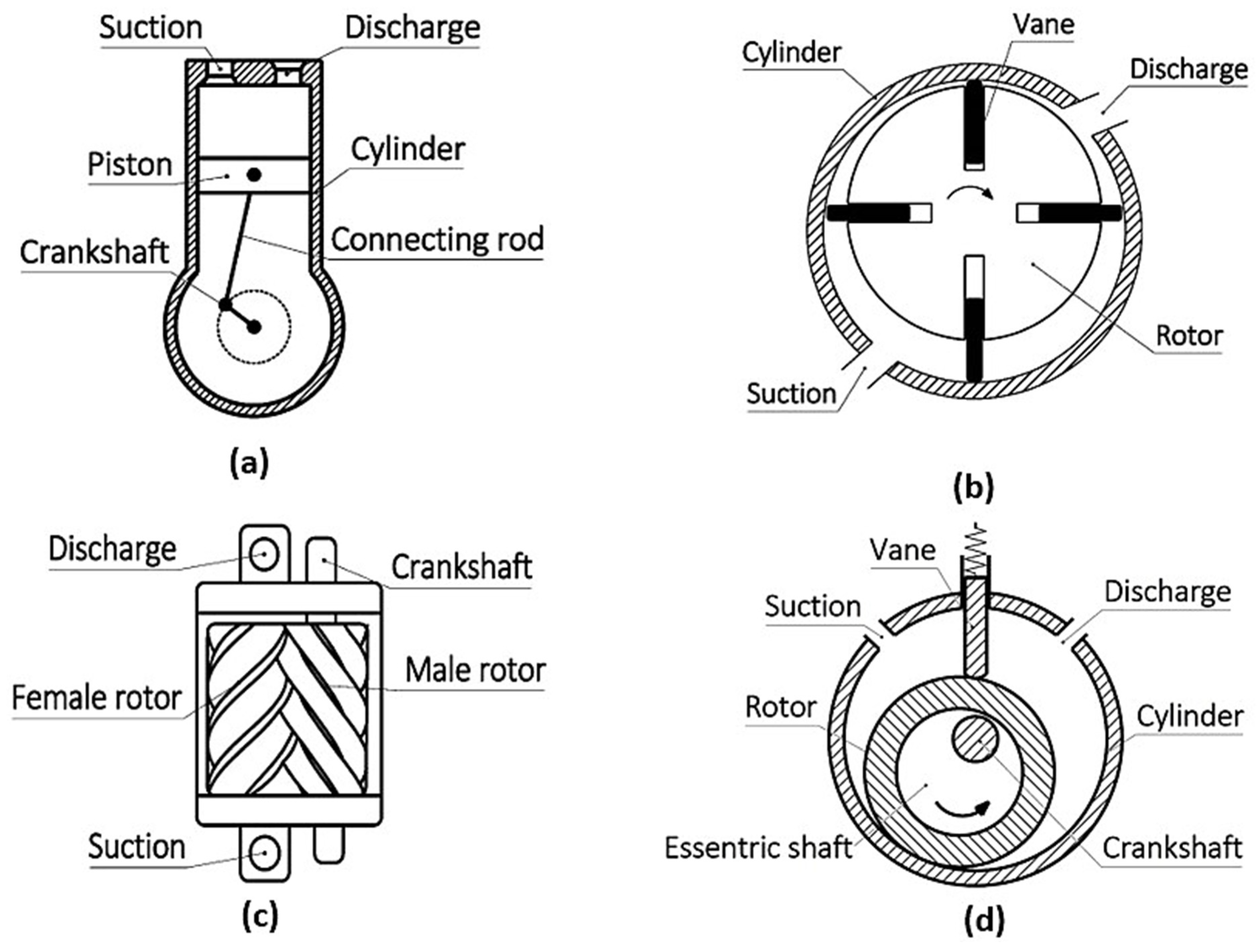
Figure 1. Common mechanisms of positive displacement compressors. (a) Reciprocating piston; (b) vane-type; (c) screw-type; (d) rolling piston type.
Energies 16 07035 g001
Figure 2. The limaçon rotary compressor.
Energies 16 07035 g002
Figure 3. An illustration of the workings of positive displacement compressors.
Energies 16 07035 g003
Figure 4. Theoretical PV diagram.
Energies 16 07035 g004
Figure 5. Structure of the reed-type valve.
Energies 16 07035 g005
Figure 6. Schematic diagram of ANN applied in positive displacement compressors.
Energies 16 07035 g006
Figure 7. A schematic diagram of GA.
Energies 16 07035 g007
Figure 8. Process of Bayesian optimisation applied in positive displacement compressor.
Energies 16 07035 g008
Table 1. Summary of various mechanisms of positive displacement compressors.
TypeOperating FeaturesMechanismPros and Cons
ReciprocatingDisplacing element moves reciprocally and linearlyPistonPros:
  • High pressure-ratio functionality
  • Flexibility to working conditions
  • Low maintenance cost
Cons:
  • Vibration issues
  • Pressure pulsation
DiaphragmPros:
  • Low level of component wear
  • Prevent contamination of fluid flow
  • Safe to work with toxic and explosive fluids
Cons:
  • Low life cycle of displacing element and low flow rate of discharge [4]
LinearPros:
  • Removal of the crank mechanism improves efficiency
  • Oil-free compression
  • Quiet operation
Cons:
  • Require accurate sensing and control methods for piston motion [5]
RotaryDisplacing element features circular or near-circular motionRolling pistonPros:
  • Simple operation and easy installation
  • Low maintenance cost
Cons:
  • Relatively low efficiency
  • Friction issues between the rotor and vane [6]
VanePros:
  • Simple operation and easy installation
  • Low maintenance cost
Cons:
  • A proper sealing scheme is needed to address internal leakage issues
ScrewPros:
  • Ability to maintain desirable performance at high speed and long service life [7]
  • Less vibration
  • Ability to handle two-phase flows
Cons:
  • High initial investment as well as maintenance cost
ScrollPros:
  • Compact size and lightweight [8]
  • Quiet operation
Cons:
  • Low capacity
  • High discharge temperature
Table 2. Recently proposed designs of positive displacement compressors.
ReferenceTypeThe Main Features of the Design
Heidari et al. [14]Reciprocating
  • Two sets of concentric fins are used as piston
  • Heat transfer increased by 32 times compared to the conventional design
  • Exergetic efficiency increased by 23.3%
Hu et al. [15]Rotary
  • Rotating cylinder design
  • Noticeable improvement in volumetric efficiency at low operating frequency
Shin et al. [16]Rotary
  • Dual cylinder design in which the additional cylinder utilises the inner space of the rotor
  • Cooling capacity improved by up to 37.99%
  • Mechanical losses reduced by 36.43%
Shakya and Ooi [17]Rotary
  • A pair of vanes coupled together and cut through the rotor diametrically
  • No geometrical constraints for rotor size, allowing the structure to be highly compact
Gao and Liu [18]Reciprocating
  • Continuously self-air-cooling
  • Performance increased significantly at high output pressure and long working time
Lu et al. [19]Rotary
  • Profiles of housing and rotor are based on the limaçon of Pascal
  • Less vibration at the rotor apex seal
  • Double-acting machine
  • High capacity can be achieved within a small machine size
Table 3. Leakage flow models.
Leakage ModelFeaturesReferences
Isentropic flow model
  • Simplest approach
  • Isentropic and compressible flow through a leakage path that can be regarded as an orifice or a convergent nozzle
  • Viscous effect is described by the empirical flow coefficient, which requires extra computational and experimental work
[23,24,25,26]
Fanno flow model
  • Adiabatic and compressible flow
  • Long but narrow flow path, which has a constant cross-sectional area
  • Viscous effect is included by using the friction factor
[28,29,30,31,32,33,34]
Incompressible flow model
  • Leakage flow is assumed to be turbulent and incompressible
  • Viscous effect is considered
  • Influence of inertial force needs to be included when the clearance and pressure exceed a certain level
[35,36,37]
Table 4. Empirical correlations proposed in different studies.
ReferencesNusselt Number CorrelationApplication
Adair et al. [39]Nu = 0.053Re0.8Pr0.6Reciprocating compressor
Liu and Zhou [40]Nu = 0.75Re0.8Pr0.6Reciprocating compressor
Hsieh and Wu [42]Pure compression N u = 0.163 R e 1.093 μ μ o 0.484 Reciprocating compressor
Compression with discharge N u = 1.64 R e d + 0.382 R e 1.166 μ μ o 0.15
where R e d is the Reynolds number based on the velocity at the beginning of the discharge process
Pure expansion N u = 0.0488 R e 1.093 μ μ o 0.484
Expansion with suction N u = 0.296 R e 1.093 μ μ o 0.484
Disconzi et al. [43]SuctionNu = 0.08Re0.9Pr0.6Reciprocating compressor
CompressionNu = 0.08Re0.8Pr0.6
DischargeNu = 0.08Re0.8Pr0.6
ExpansionNu = 0.012Re0.8Pr0.6
Jang and Jeong [45] N u = 1 + 3.5 D h D c 1 + 8.48 1 e 5.35 S t 0.023 R e 0.8 P r 0.6
where Dc is the diameter of the curvature, and St is the Strouhal number
Scroll compressor
Table 5. Comparison of different capacity control methods.
MethodsPrinciplePros and ConsReferences
Stepless controlThe closing of the suction valve is delayed by an external force, allowing excess fluid to flow out of the working chamberPros:
  • Theoretically, capacity adjustment ranges from 0 to 100%
Cons:
  • Fatigue and wear consequences on the suction valve due to the reverse flow
[81,82,83,84,85,86,87,88,89,90]
Speed controlOperating speed is regulated to match the working loadPros:
  • Most energy-efficient
Cons:
  • High cost of variable-speed drives for large-scale applications
  • Difficult to ensure reliable valve operation
  • Mechanical resonance, pulsation, and torsional-related issues might occur
[91,92,93,94]
BypassCompressed fluid is bypassed to the suction line before delivering, thus reducing the capacityPros:
  • The simplest way to apply
Cons:
  • Compression work on the bypassed fluid is wasted
  • Usually requires a heat exchanger to cool the bypassed fluid
[95,96,97]
Clearance pocketAdditional clearance volume is introduced to the working chamberPros:
  • Compression work on the fluid in the clearance area can be recovered
Cons:
  • Less efficient with low compression ratios
[98,99,100,101]
Suction throttlingReduce the suction pressure by throttling the fresh charge via the control valve at the suctionPros:
  • Least costly and easy to apply
Cons:
  • High discharge temperature
  • Worst performance
[98,99,100,101]
Table 6. Summary of machine learning methods applied in positive displacement compressors.
MethodsType of CompressorApplicationsReferences
ANNSliding vaneDetection of valve failure[105]
ReciprocatingMathematical modelling[106,107]
ScrollPerformance prediction[108,109]
GASliding vaneImprovement of mechanical efficiency[111]
Coupled vaneOptimisation of rotor-chamber configuration[112]
ReciprocatingOptimisation of valve actuator and piston trajectory[88,89,113]
Bayesian optimisationLimaçon (rotary)Optimisation of port geometry[114,115]
SPSAReciprocatingOptimisation of piston trajectory[116]
Limaçon (rotary)Machine geometric design[117]
PCAReciprocatingFault diagnosis[118]
Reliability improvement[119]
Disclaimer/Publisher’s Note: The statements, opinions and data contained in all publications are solely those of the individual author(s) and contributor(s) and not of MDPI and/or the editor(s). MDPI and/or the editor(s) disclaim responsibility for any injury to people or property resulting from any ideas, methods, instructions or products referred to in the content.