Article

Investigation of the Heat Storage Capacity and Storage Dynamics of a Novel Polymeric Macro-Encapsulated Core-Shell Particle Using a Paraffinic Core

by
Matthias Singer
1,
Michael Fischlschweiger
2,* and
Tim Zeiner
1,*
1
Process Systems Engineering, TU Graz, Inffeldgasse 25C, 8010 Graz, Austria
2
Institute of Technical Thermodynamics and Energy Efficient Material Treatment, Institute of Energy Process Engineering and Fuel Technology, Clausthal University of Technology, Agricolastraße 4, 38678 Clausthal-Zellerfeld, Germany
*
Authors to whom correspondence should be addressed.
Energies 2023, 16(2), 957; https://doi.org/10.3390/en16020957
Submission received: 20 December 2022 / Revised: 10 January 2023 / Accepted: 12 January 2023 / Published: 14 January 2023
(This article belongs to the Special Issue Phase Change Materials for Thermal Energy Storage Applications 2022)

Abstract

:
Thermal energy storages represent important devices for the decarbonisation of heat; hence, enabling a circular economy. Hereby, important tasks are the optimisation of thermal losses and providing a tuneable storage capacity, as well as tuneable storage dynamics for thermal energy storage modules which are composed of either sensible or phase change-based heat storage materials. The thermal storage capacity and the storage dynamics behaviour are crucial for fulfilling certain application requirements. In this work, a novel macro-encapsulated and spherical heat storage core-shell structure is presented and embedded in a supercritical ammonia working fluid flow field. The core of the macro-capsule is built by an organic low molecular weight substance showing a solid–liquid phase transition in a respective temperature zone, where the shell structure is made of polyvinylidene fluoride. Due to the direct coupling of computational fluid dynamics and the simulation of the phase transition of the core material, the influence of the working fluid flow field and shell thickness on the time evolution of temperature, heat transfer coefficients, and accumulated heat storage is investigated for this newly designed material system. It is shown that due to the mixed sensible and phase change storage character, the shell architecture and the working fluid flow field, the heat storage capacity and the storage dynamics can be systematically tuned.

1. Introduction

Energy storage is important for the transition to a more sustainable economy. Hereby, it is important that also heat waste streams are used [1] and heat is stored [2]. In general, this waste heat could be used on site of the production, e.g., by the application of organic Rankine cycles [3]. However, this is often not completed as it would disturb the process or because of the lack of a heat sink. Therefore, the storage of this thermal energy is reasonable. For the thermal energy storage, there are, in general, two available ways: sensitive or latent heat storages [4]. Sensitive heat storages utilise the storage capacity of different media, such as water or rocks, whereas latent heat storages utilise a change in the state, e.g., by phase transition. By means of this, the storage cost per kWh depends on the applied material including the material itself, equipment, and operation costs. Costs for the sensitive energy storages are very low as the materials are cheap and the equipment is simple [5]. The costs for the latent heat storages are higher because of the material itself and more complex equipment [6]. However, materials such as phase change materials (PCM), which apply the solid–liquid phase transition, have the advantage that the heat is mainly supplied at one temperature from which a latent heat storage process can be designed. On this basis, many applications have been suggested. One application is the storage of waste heat as its provided temperature in internal combustion engines [7]. This could be in the form of the heat recovery of the exhaust streams, thermal management, catalytic conversion, the regulation system, or as preheaters. Hereby, the stored heat is applied as fuel, preheating to increase the catalytic efficiency or for industrial heating. Other applications are solar water heating [8]. The challenge for this application is that the maximum of the solar radiation lies near noon, but the energy demand maximum is in the morning or in the evening. Here, the phase change materials are applied to bridge the gap. Next to the solar water heating, the green-house heating was also optimized [9]. The energy consumption in agriculture is mainly based on greenhouse heating. Hereby, it is important that the phase change temperature should be close to a suitable temperature for each plant, which can be optimized by PCMs. The temperature control in buildings [10,11] is also a potential application field of PCMs. However, up to now, these applications are only at lab-scale. The challenges are to find PCMs in the desired temperature range and the lack of understanding due to the complex heat and mass transfer behaviour in the buildings. An exotic application is PCMs in smart textiles [12]. Hereby, the textiles are impregnated or coated with the PCMs for the thermoregulation of the body.
For all the mentioned applications, several thermodynamic properties are limiting [13,14]. At first, the melting temperature of the PCM has to be in the application range. To influence this temperature range, mixtures of different PCMs are also reasonable. Furthermore, the latent heat of fusion has to be high per volume unit to reduce the unit scale. The conductivity of the PCM in solid and molten state must be high for an optimal loading and de-loading process. Moreover, the volume change throughout the phase transition must be small to avoid mechanical tension. Further, the vapour pressure of the liquid should be small. For the mixtures, it is important that a congruent melting is achieved over time so that there is no change in the melting temperature over time by the formation of different phases. Next to the equilibrium properties, the kinetics are also important. Therefore, a high nucleation rate is required to ensure the melting temperature range. Otherwise, there could be a super cooling of the liquid phase. Moreover, the crystal growth must be as high to fulfil the requirements due to the heat source. Additionally, some chemical characteristics need to be meet. One is the chemical stability of the PCM and the degradation reduction after some cycles. Further, the PCMs should be non-corrosive to directly apply in combination with cheap metals. The PCMs also have to meet the conditions of non-toxicity, non-flammable, and non-explosive because of safety issues.
There are several materials available which fulfil these conditions to a special degree. One group is the organic materials [15]. Here, the paraffins, as long chain alkanes, play a special role. They have a melting temperature between 23 °C and 67 °C, so they are applicable for low temperature storages, whereas the heat of fusion and melting temperature is growing with temperature. They are thermal stable if no oxygen is present and do not degrade. On the other hand, they have low thermal conductivity and show higher volume changes between the states. Further, organic PCMs are small organic molecules, such as fatty acids, esters, or alcohols. Fatty acids show similar properties as the paraffins but are more expensive, and the purity of the long chain fatty acids is low. This influences their melting temperature and the congruent melting. Promising organic materials are polymers. Two examples are polyalcohol or polyethylene. In the literature [8], the higher costs are mentioned but they are bulk-chemicals. The true disadvantage is the low heat conductivity. Next to the organic materials, inorganic materials are also applied, e.g., salt hydrates or metals [16]. Hereby, the salts crystalize from an aqueous solution in a crystal structure with water. The problems are the incongruent crystals and the slow nucleation rate. However, they have a high phase change enthalpy and cheap materials. Metals also have the problem of supercooling and have a phase change temperature range from 120–1500 °C. A further intensification of the application are metal as foams [17] with other material to increase the heat conductivity to improve the temperature profile. PCMs can also be formed by mixtures, whereas the congruent melting behaviour has to be given. This is the case with the application of eutectic mixtures [18]. They can be formed by organic and inorganic mixtures. Hereby, also deep eutectic solvents [19] could be used as phase change material.
For some of the PCMs, an encapsulation is required [20]. In this case, the PCMs are covered with a coating material or inserted in a matrix. Hereby, different polymerisation methods such as in situ polymerisation, interfacial polycondensation, or suspension polymerisation are applied. Furthermore, shell materials could be applied [12,21]. One challenge left is how to pack the PCMs in the equipment, which has to be investigated in a laborious experimental manner. Computational fluid dynamics (CFD) models help to reduce the experimental effort [22,23,24,25,26,27]; whereas, it has to distinguished if the phase behaviour of the PCM itself will be modelled or the application of the PCM in large-scale. For the simulation of the PCM, the surface between the solid and the liquid phase has to be traced and a two-phase system has to be modelled. For large-scale simulations, a model for the PCM phase transition has to be established describing the released heat, conductivity, and heat loading. Several different applications [28,29,30] have been simulated applying PCM as the thermal management in fuel cells applying PCMs [31], the thermal management in automotive [32], or a rotating latent heat storage [33]. A special challenge is the simulation of the core-shell PCM [34]. Hereby, one example is the study of the temperature field during the differential scanning calorimetry (DSC) analysis of core-shell PCM. It was shown that the shell influenced enormously the thermal characteristics of the PCM. Thereby, the fluid flow was omitted. For PCM modelling, there are only few modelling approaches considering, correctly, the phase transition, but the interaction with the superimposed flow was omitted [35,36]. Therefore, the super cooling of the PCMs cannot be represented correctly.
This work investigates the interaction between the PCM and the fluid. To analyse the behaviour of the core-shell capsules, numerical experiments were performed. One intention of this work is the calculation of the flow-dependent heat transfer coefficient of a polyvinylidene fluoride (PVDF) shell and an n-eicosane core model exposed to a supercritical ammonia flow. Data for the applied paraffinic PCM, i.e., n-eicosane, are well available in high quality in the literature; this holds true for the used PVDF in the low temperature range between 20 °C and 80 °C. The combination of PVDF as encapsulation material with a paraffinic core PCM is attractive in terms of the high durability properties of PVDF and is investigated herein for the first time.

2. Methods—Computational Fluid Dynamics

The CFD simulations were carried out using the software Ansys Fluent 2020 R1. In this chapter the simulation domain and the phase transition model for the PCM will be introduced in order to describe the transient heat storage behaviour of the n-eicosane/PVDF core-shell particle. The core-shell particle is placed in a supercritical ammonia flow field for the heat loading process. Hereby, the influence of the shell thickness and the flow field on the heat storage properties will be analysed.

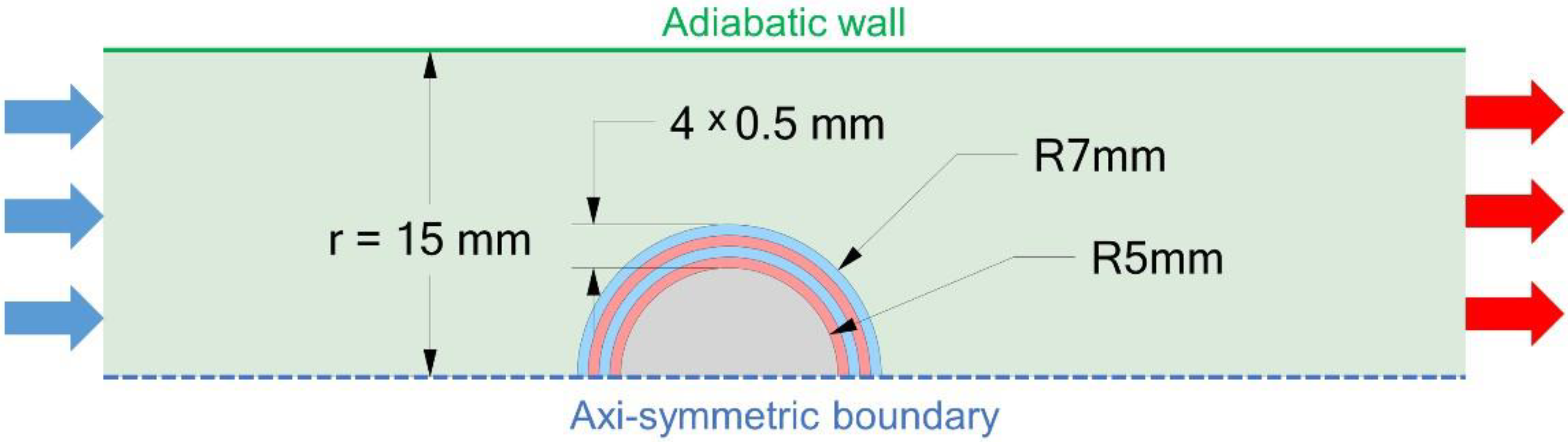
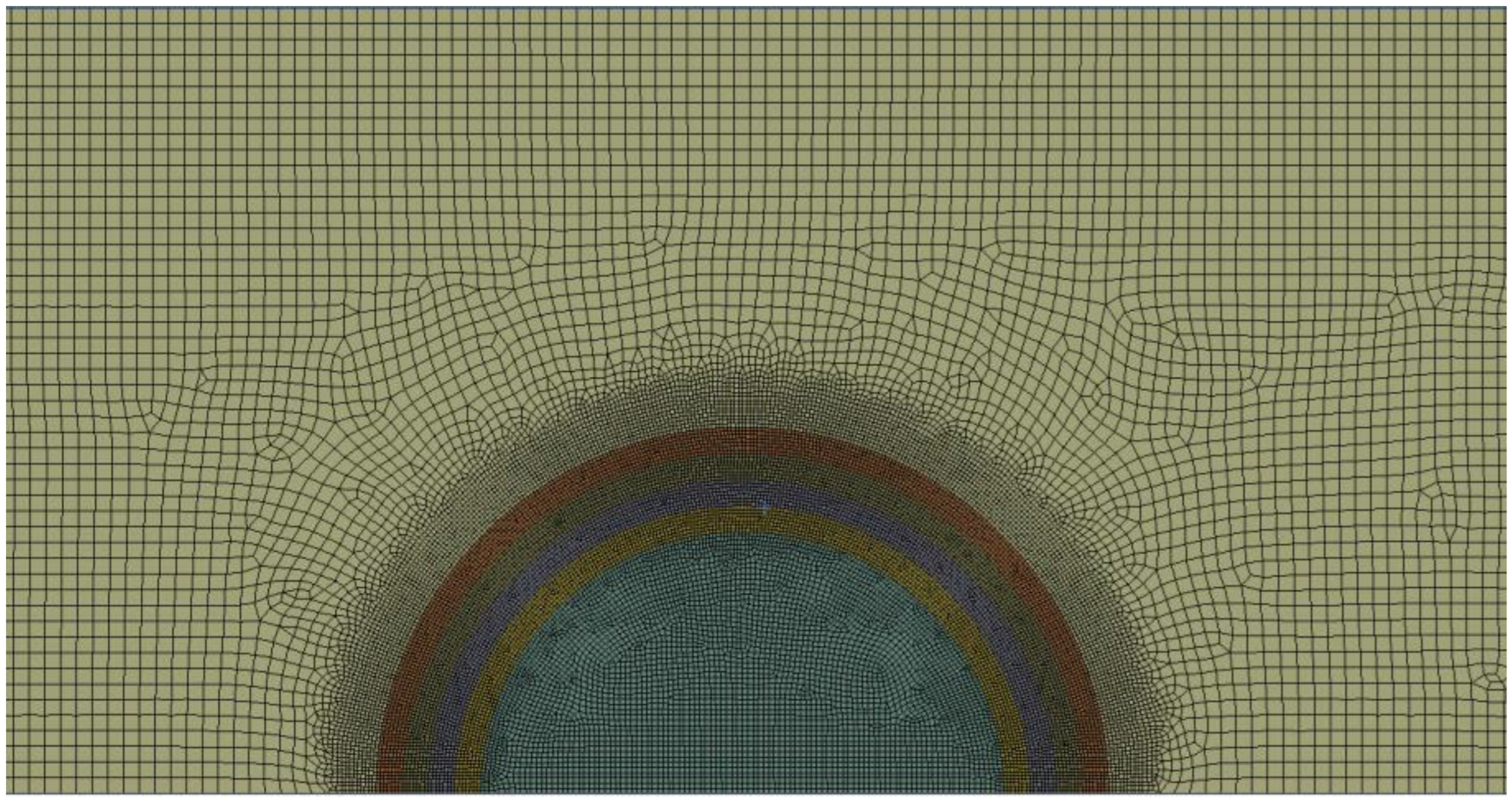
2.1. Simulation Domain and Boundary Conditions

The geometry of the simulation domain was chosen with axial symmetry to the centre line as shown in Figure 1. Thereby, the simulation domain is an adiabatic cylindrical chamber. The ammonia flow is introduced with a temperature of 140 °C and the core-shell particle filled with the PCM is placed in the centre of the domain.
In the simulation domain, the mass, momentum, and energy balances for the ammonia flow are solved, whereas the core-shell particle is represented by the energy balance. Here, just the heat conduction is considered. The simulation domain is discretized using a mesh of quadrilateral cells, whereas the number of quadrilateral cells in the fluid–solid interfacial region was increased for a more accurate representation of the heat transfer between the fluid and the particle. The computational mesh consists of 42,122 cells with a maximal skewness of 0.64 and is represented in Figure 2. Investigating the mesh sensitivity with respect to the accuracy of the results and computational effort, it was found that this computational mesh was the best choice for the simulations.
An important factor for the heat transfer between the liquid and the solid is the turbulence behaviour. In this work, the turbulence is modelled via a Reynolds-Averaged Navies–Stokes (RANS) approach by the application of the SST (Shear Stress Transport) k-ω model [37] such as the two-equation eddy-viscosity model. The application of the k-ω model in the inner part of the boundary allows to model the viscous sublayer. The advantage of the SST k-ω model is a numeric robust and realistic representation of separating flows, which is important for fluid flows past a spherical geometry.
Since the CFD simulations are performed transient, following simulation strategy is conducted: first, a steady-state ammonia flow field with 140 °C is established. When the simulation converges to the steady-state point, the core-shell particle is placed in the centre of the flow field having a temperature of 20 °C. The time dependent balance equations are then solved starting at time t = 0 s. The simulations were performed with different ammonia velocities (2 m/s, 6 m/s, and 30 m/s), which are corresponding to a laminar, transition, and slightly turbulent flow. Furthermore, the shell thickness was varied in a range between 0 and 2 mm with 0.5 mm steps. The material parameters for the simulation are presented in Table 1 and can also be found in [38,39] for PVDF and n-eicosane represented in graphical form.

2.2. Phase Transition Model Approach

The solid/liquid phase transition of the n-eicosane core is a heat conduction dominant process. Therefore, the energy balance of the core-shell particle can be formulated as follows:
ρ e t = ( λ T ) + Δ h lat
where the left-hand side represents the local change of energy in each cell with respect to time, and the first term on the right-hand side is the change in energy due to conductive heat transfer. The second term Δ h lat is the latent heat sink calculated with a semi-empirical modelling approach similar to the approach of Kumarasamy et al. They fitted the isobaric heat capacity (cP) curves of the PCM to the corresponding curves obtained from differential scanning calorimetry (DSC) measurements [34]. By the integration of the cp-curves with respect to the temperature, which is obtained in every time step during the simulation, the latent heat can be obtained as follows:
Δ h lat = ρ Δ t T t 1 T t c p , m ( T ) d T
(2) is considered in the simulation as soon as the onset of the melting temperature is reached until the whole PCM is molten. Furthermore, during the melting process, the entropy of the n-eicosane increases. The data for the fit of the isobaric heat enthalpies are taken from the literature [39]. Therefore, a triangular approximation of the cp curve is applied for the DSC curves measured with 0.1 K/min. The coefficients of the triangular fit for n-eicosane can be found in Table 1 for the phase transition region between 305.92 and 313.19 K. The left and right limits of the triangular fit are adjusted to the onset and offset of the melting process. The amplitude of the triangular fit is determined via the integral between onset and offset, which corresponds to the latent heat of n-eicosane 253.1 kJ/kg. The triangular fit has the advantage compared to a constant energy heat sink or more complex fitting functions; that simple function can be easily integrated with low computational effort. Furthermore, numerical stability is assured while simultaneously coupling the triangular function to the heat conduction and to the heat flow of the ammonia.

3. Results

In this section, the heat storage behaviour of the PCM core-shell particle composed of a PVDF shell and an n-eicosane core is presented, whereas ammonia is the applied working fluid which loads the particle with heat. Several important conditions with their respective influences on heat storage behaviour are evaluated and discussed in detail. This gives fundamental insights into the energy storage of this PCM construction, which uses combined mechanisms, i.e., sensible and phase change based storage, due to the core-shell architecture. First of all, the evolution of the temperature field within the core-shell particle is analysed independent of different working fluid inflow velocities and shell thicknesses. Further, the inflow velocity-dependent average PVDF temperature evolution over time is analysed in the shell. Specific attention is paid to the time evolution of the heat transfer coefficient at the interface between the outer shell surface and the working fluid, where the impact of shell thickness and inflow velocity is investigated. Finally, the inflow velocity and shell thickness-dependent heat flow, as well as the heat accumulation versus storage in a specific loading time interval, is calculated and gives first insights into the dynamics of the heat loading of the core-shell PCM.

3.1. Temperature Field of the Core-Shell Particle during Heat Loading Process

The working fluid ammonia transports the heat to the spherical core-shell particle and loads the particle with thermal energy. The working fluid has an inflow temperature of 140 °C, while the core-shell particle has an initial temperature of 20 °C. The particle uptakes the heat at the very beginning, sensibly. The solid–liquid phase transition of the n-eicosane core occurs in the temperature range of 35.0 and 39.5 °C, which is in a similar range as the experimental data [1], and the storage behaviour becomes dominated by the latent heat due to the phase change. After this transition, the thermal energy storage turns back into the sensible mechanism again. The temperature does not reach values which induce phase changes in the polymer, such that the shell behaves purely, similar to a sensible heat storage component within the PCM particle. In Figure 3, the spatial temperature field evolution over three loading time steps, i.e., 30, 60, and 90 s, is shown with the combined impact of the shell thickness. The shell thickness is varied from zero to 2.0 mm, while a zero shell thickness serves as a mere theoretical case. This presents the case where, theoretically, no shell is present and the pure core material is loaded, which is, of course, not possible because of the missing geometric stability of liquid n-eicosane after phase transition; rather, it is more important to compare shell influences. Figure 3 presents the different cases for an ammonia inflow velocity of 2 m/s. Additionally, the same cases are visualized in Figure 4, but now for an inflow velocity of 30 m/s where the start of the turbulent flow regime occurred. Figure 3 demonstrates that under laminar inflow conditions, an asymmetric temperature field is generated, while the shell thickness has a strong influence on the time interval where the phase transition of the core material occurs and, hence, it allows the design of the latent storage dynamics. In contrast to a laminar flow field, in a turbulent flow field, an almost geometrically symmetric temperature profile develops in general with a smaller transition time interval. However, also for the turbulent case, the shell thickness strongly influences the heat storage dynamics. This can be intuitively seen by the transition characteristics of the zero shell thickness case compared to the 2.0 mm shell thickness investigations. While the zero shell thickness particle has nearly fully transformed to the liquid state after 90 s of thermal energy loading, the n-eicosane core of the particle with a 2 mm shell thickness has only transformed with an amount of approximately 60% after 90 s of loading time. Therefore, the thermal energy loading kinetics are completely different according to the shell architecture of the composite PCM. This can, in turn, be used as a design element for the dynamics of the heat loading of the PCM. Additionally, it can be mentioned that a PVDF shell thickness of 0.5 mm, which is a minimal thickness in terms of production feasibility, influences the dynamics of the heat storage only slightly compared to the theoretical case, where a zero shell thickness is applied and a direct contact of ammonia and the core material n-eicosane is assumed. This means that the lag effect, due to the shell itself, is small in terms of temperature, on the one hand, and gives the PCM core the necessary stability and durability such that the particle stays in the spherical shape, on the other hand. The stability of the spherical shape is important in the context that due to the shell and the spherical shape of the PCM, a directly in the working fluid integrated heat exchanger with an optimal surface-to-volume ratio is generated, accompanied with the tuneable shell-based dynamics of the composite PCM. This makes the macroscopic PCM composite attractive compared to the state of the art PCMs, where the PCM is filled in certain, e.g., rib-like, geometry, and the constructions act, then, as a classical heat exchanger, with respective drawbacks in losses of heat and dynamics.

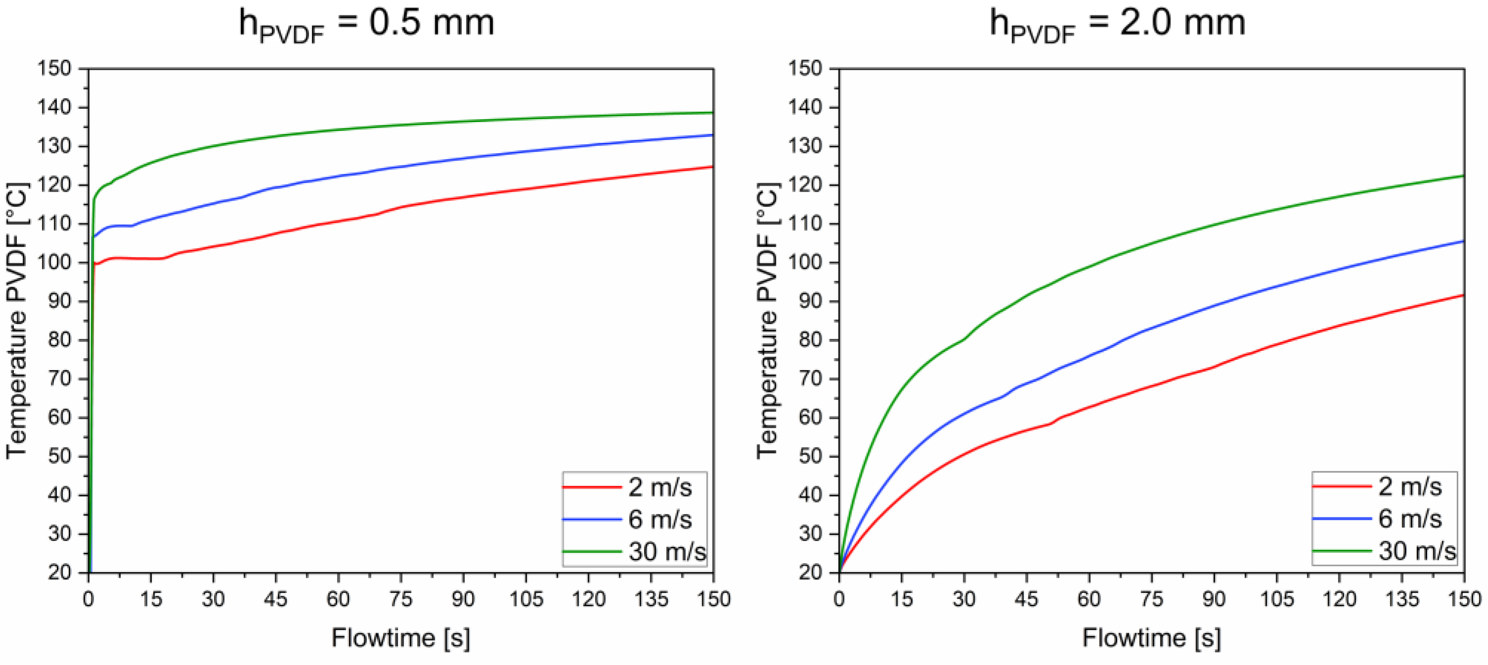
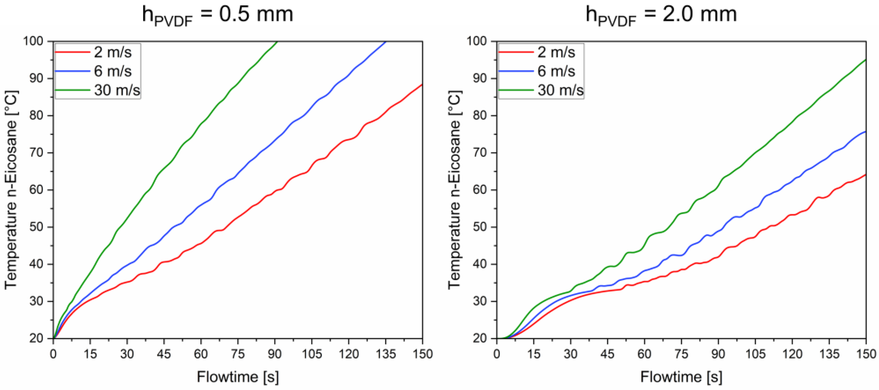
3.2. Velocity-Dependent Average Temperature Evolution in the PVDF Shell and the n-Eicosane Core

To better understand the influence of the inflow velocity and the transition between the laminar and turbulent flow field, and consequently its influence on the thermal energy loading behaviour, in this subsection, the average temperature of the shell surface and the average core temperature of the n-eicosane in a loading time interval of 150 s is visualized for three different ammonia inflow velocities. The results are shown in Figure 5 and Figure 6. Figure 5 illustrates that independent of the shell thickness and the inflow velocity, on the one hand, very different temperature levels at a certain loading time evolve, and on the other hand, the phase change time interval also strongly depends on these respective input parameters. It is seen for the shell thickness of 0.5 mm that transition between phase change dominated storage, and sensible storage is shifts from 5 to approximately 20 s according to the inflow velocity change from 30 to 2 m/s. Comparing these results with the shell thickness of 2.0 mm under the same conditions, the phase change-dominated thermal energy storage time interval is significantly stretched. It is shown that the transition between latent heat and sensible dominated storage occurs at around 30 s for an inflow velocity of 30 m/s and approximately at 50 s for an inflow velocity of 2 m/s. This is seen more clearly in Figure 6 where the average temperature of the n-eicosane core is given for 2 shell thicknesses. The plateau behaviour of the temperature-time curves indicates the phase change time window. Before and after the plateau shape of the temperature-time curve, the heat uptake is dominated by sensible storage. However, it has to be emphasized that the conclusions drawn here refer to the technologically dominating and in the storage activity leading mechanism. This does not mean, for example, that after the sensible heat storage becomes the leading mechanism again, that n-eicosane is yet fully melted.
Rather, there is still melting of n-eicosane, even in the flowtime region where sensible heat storage is the leading heat uptake mechanism. In other words, this means that the amount of melted n-eicosane is approaching a lower rate, which contributes, in turn, to a lower heat uptake due to phase change compared to sensible storage. The flowtime, where all of the n-eicosane is in the molten state for different cases in terms of inflow velocity and shell thickness, is presented in Table 2.

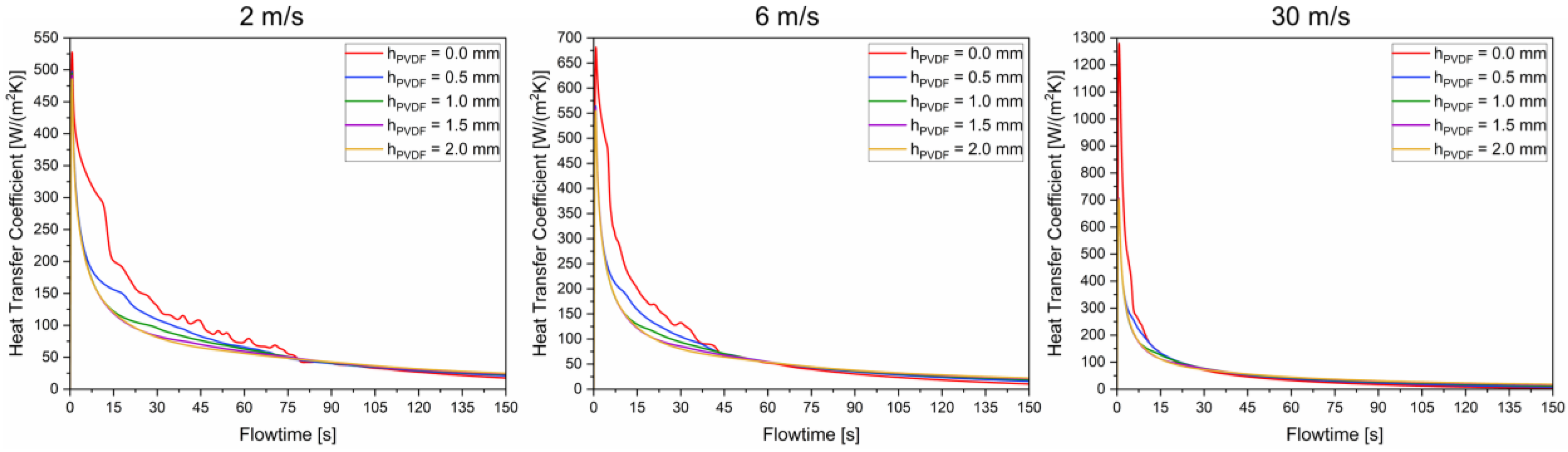
3.3. Influence of Shell Thickness and Working Fluid Velocity on the Heat Transfer Coefficient

A further important property for thermal energy storage is the heat transfer coefficient at the interface between the PVDF shell and the working fluid. The heat transfer coefficients are averaged over the interface between the solid and the ammonia for different inflow velocities and shell thicknesses. They are presented as an evolution over flowtime in Figure 7.
In a laminar flow field, significant differences between the heat transfer coefficients can be found in the early flowtime region independent of shell thickness. This difference loses its significance when higher inflow velocities are applied and almost disappear at an inflow velocity of 30 m/s. This result emphasizes that, perhaps, unwanted lower heat transfer coefficients at the interface between the working fluid and the PCM particle due to the shell architecture can be easily tuned by adjusting the flow velocity. This also underpins the necessity of the coupled consideration of working fluid and PCM under flow and thermal energy loading conditions, rather than evaluating working fluid and PCM behaviour in a singular consideration as it is typically done in the literature today.

3.4. Impact of Shell Thickness and Working Fluid Velocity on the Heat Flow and Storage Capacity

In the last section, the time-dependent heat flow and, further, the time interval-dependent storage capacity of the thermal energy storage system are studied. This is of particular relevance for engineering purposes and for comparison with other PCM designs. In Figure 8, the net heat flow of ammonia over flowtime between outlet and inlet for several shell designs and two inflow velocities is illustrated. The more negative the heat flow is, the more heat is stored in the PCM, and the higher the storage capacity. First of all, it is shown that, in general, higher inflow velocities, corresponding to a turbulent flow field, lead to a higher thermal energy storage capacity of the system. Further, the shell thickness influences the storage capacity in the laminar, as well as in the turbulent flow regime. The higher the shell thickness, the higher the storage capacity. This is due to the sensible heat storage contribution of the shell, and it can be concluded that even such thin shell dimensions of a PVDF have a substantial share of the storage capacity of the herein proposed core-shell particle.
To comprehensively summarize the accumulated heat of the proposed and investigated system, in Table 3, the respective values are listed for different inflow velocities and shell thicknesses. It can be seen that the heat accumulation spans from around 175 to 490 J independent of the PCM-working fluid configuration in a flowtime interval of 150 s.

4. Conclusions

In this work, a core-shell particle composed of a PVDF shell and an n-eicosane core is developed as a thermal storage component, which is based on sensible heat storage and phase change-based latent heat storage. This particular material combination, by considering temperature-dependent thermophysical property data of both, core, and shell, is investigated herein for the first time.
The PCM particle is exposed to a working fluid, i.e., ammonia; hence, the interaction of working fluid flow-induced thermal energy loading of the core-shell particle is investigated for different boundary conditions. Special focus is put on the time evolution of the spatial temperature within the core-shell particle by directly considering the solid–liquid phase transformation. Thereby, the dynamics of the storage behaviour are investigated and can be systematically controlled by the inflow velocity in terms of laminar and turbulent flow environments and the shell thickness of the PCM particle. It was found that the heat transfer coefficient was almost doubled by transitioning from laminar to a turbulent flow regime (approx. 600 to 1300 W/(m² K)).
Furthermore, the transition zone in the respective flowtime frame between sensible and phase change-dominated thermal energy storage is calculated and it is shown in detail how the transition zone can be tuned by the composition of the core-shell particle and the specific interaction with the working fluid. Based on this work, it is demonstrated how the non-linear heat accumulation and storage behaviour of a PVDF shell and n-eicosane core particle behaves and that due to the construction and the working fluid, the storage capacity in combination with the dynamics can be tailored. The investigated particle has a spherical form and ensures an optimal surface-to-volume ratio; as well, it avoids any agglomeration and segregation effect due to the macro-encapsulation strategy. Thus, the core-shell particle has a high potential to build up a thermal energy storage module, filled with these core-shell-particles having direct contact with the working fluid and, hence, provide a directly integrated and, in terms of losses, optimized heat exchanger. This work provides the base for studying and developing an integrated heat storage module by using PVDF-based core-shell particles with direct working fluid contact in the future.

Author Contributions

Conceptualization, M.S. and M.F.; methodology, M.S. and M.F.; software, M.S.; formal analysis, M.F. and T.Z.; investigation, M.S.; resources, T.Z.; writing—original draft, M.S., M.F. and T.Z.; writing—review and editing, M.F. and T.Z.; visualization, M.S.; supervision, M.F.; project administration, M.F. and T.Z. All authors have read and agreed to the published version of the manuscript.

Funding

This research received no external funding.

Data Availability Statement

The data presented in this study are available upon request from the correspondent authors.

Conflicts of Interest

The authors declare no conflict of interest.

References

  1. Miró, L.; Gasia, J.; Cabeza, L.F. Thermal energy storage (TES) for industrial waste heat (IWH) recovery: A review. Appl. Energy 2016, 179, 284–301. [Google Scholar] [CrossRef] [Green Version]
  2. Kalair, A.; Abas, N.; Saleem, M.S.; Kalair, A.R.; Khan, N. Role of energy storage systems in energy transition from fossil fuels to renewables. Energy Storage 2021, 3, e135. [Google Scholar] [CrossRef] [Green Version]
  3. Preißinger, M.; Brüggemann, D. Thermoeconomic evaluation of modular organic Rankine cycles for waste heat recovery over a broad range of heat source temperatures and capacities. Energies 2017, 10, 269. [Google Scholar] [CrossRef] [Green Version]
  4. Dincer, I.; Rosen, M.A. Thermal Energy Storage: Systems and Applications; John Wiley & Sons: New York, NY, USA, 2021. [Google Scholar]
  5. Benalcazar, P. Optimal sizing of thermal energy storage systems for CHP plants considering specific investment costs: A case study. Energy 2021, 234, 121323. [Google Scholar] [CrossRef]
  6. Ramos, A.; López, E.; del Cañizo, C.; Datas, A. Cost-effective ultra-high temperature latent heat thermal energy storage systems. J. Energy Storage 2022, 49, 104131. [Google Scholar] [CrossRef]
  7. Omara, A.A. Phase change materials for waste heat recovery in internal combustion engines: A review. J. Energy Storage 2021, 44, 103421. [Google Scholar] [CrossRef]
  8. Sharma, A.; Chen, C.R. Solar water heating system with phase change materials. Int. Rev. Chem. Eng. 2009, 1, 297–307. [Google Scholar]
  9. Mu, M.; Zhang, S.; Yang, S.; Wang, Y. Phase change materials applied in agricultural greenhouses. J. Energy Storage 2022, 49, 104100. [Google Scholar] [CrossRef]
  10. Baetens, R.; Jelle, B.P.; Gustavsen, A. Phase change materials for building applications: A state-of-the-art review. Energy Build. 2010, 42, 1361–1368. [Google Scholar] [CrossRef] [Green Version]
  11. Kuznik, F.; David, D.; Johannes, K.; Roux, J.J. A review on phase change materials integrated in building walls. Renew. Sustain. Energy Rev. 2011, 15, 379–391. [Google Scholar] [CrossRef] [Green Version]
  12. Mondal, S. Phase change materials for smart textiles-An overview. Appl. Therm. Eng. 2008, 28, 1536–1550. [Google Scholar] [CrossRef]
  13. Zalba, B.; Marın, J.M.; Cabeza, L.F.; Mehling, H. Review on thermal energy storage with phase change: Materials, heat transfer analysis and applications. Appl. Therm. Eng. 2003, 23, 251–283. [Google Scholar] [CrossRef]
  14. Sharma, S.D.; Sagara, K. Latent heat storage materials and systems: A review. Int. J. Green Energy 2005, 2, 1–56. [Google Scholar] [CrossRef]
  15. Zhao, Y.; Zhang, X.; Hua, W. Review of preparation technologies of organic composite phase change materials in energy storage. J. Mol. Liq. 2021, 336, 115923. [Google Scholar] [CrossRef]
  16. Lin, Y.; Alva, G.; Fang, G. Review on thermal performances and applications of thermal energy storage systems with inorganic phase change materials. Energy 2018, 165, 685–708. [Google Scholar] [CrossRef]
  17. Aramesh, M.; Shabani, B. Metal foams application to enhance the thermal performance of phase change materials: A review of experimental studies to understand the mechanisms. J. Energy Storage 2022, 50, 104650. [Google Scholar] [CrossRef]
  18. Singh, P.; Sharma, R.K.; Ansu, A.K.; Goyal, R.; Sarı, A.; Tyagi, V.V. A comprehensive review on development of eutectic organic phase change materials and their composites for low and medium range thermal energy storage applications. Sol. Energy Mater. Sol. Cells 2021, 223, 110955. [Google Scholar] [CrossRef]
  19. Smith, E.L.; Abbott, A.P.; Ryder, K.S. Deep eutectic solvents (DESs) and their applications. Chem. Rev. 2014, 114, 11060–11082. [Google Scholar] [CrossRef] [Green Version]
  20. Su, W.; Darkwa, J.; Kokogiannakis, G. Review of solid–liquid phase change materials and their encapsulation technologies. Renew. Sustain. Energy Rev. 2015, 48, 373–391. [Google Scholar] [CrossRef]
  21. Wang, H.; Chen, Y.; Li, J.; Guo, L.; Fang, M. Review of encapsulated salt hydrate core-shell phase change materials. KONA Powder Part. J. 2020, 37, 85–96. [Google Scholar] [CrossRef] [Green Version]
  22. Dutil, Y.; Rousse, D.R.; Salah, N.B.; Lassue, S.; Zalewski, L. A review on phase-change materials: Mathematical modeling and simulations. Renew. Sustain. Energy Rev. 2011, 15, 112–130. [Google Scholar] [CrossRef]
  23. Al-Abidi, A.A.; Mat, S.B.; Sopian, K.; Sulaiman, M.Y.; Mohammed, A.T. CFD applications for latent heat thermal energy storage: A review. Renew. Sustain. Energy Rev. 2013, 20, 353–363. [Google Scholar] [CrossRef]
  24. Xiao, X.; Zhang, P. Numerical and experimental study of heat transfer characteristics of a shell-tube latent heat storage system: Part I–Charging process. Energy 2015, 79, 337–350. [Google Scholar] [CrossRef]
  25. Bouzennada, T.; Mechighel, F.; Ghachem, K.; Kolsi, L. Numerical Simulation of the Impact of the Heat Source Position on Melting of a Nano-Enhanced Phase Change Material. Nanomaterials 2021, 11, 1425. [Google Scholar] [CrossRef] [PubMed]
  26. Maneengam, A.; Bouzennada, T.; Abderrahmane, A.; Guedri, K.; Weera, W.; Younis, O.; Bouallegue, B. Numerical Study of Lid-Driven Hybrid Nanofluid Flow in a Corrugated Porous Cavity in the Presence of Magnetic Field. Nanomaterials 2022, 12, 2390. [Google Scholar] [CrossRef]
  27. Maneengam, A.; Bouzennada, T.; Abderrahmane, A.; Ghachem, K.; Kolsi, L.; Younis, O.; Guedri, K.; Weera, W. Numerical Study of 3D MHD Mixed Convection and Entropy Generation in Trapezoidal Porous Enclosure Filled with a Hybrid Nanofluid: Effect of Zigzag Wall and Spinning Inner Cylinder. Nanomaterials 2022, 12, 1974. [Google Scholar] [CrossRef]
  28. Bouzennada, T.; Mechighel, F.; Ismail, T.; Kolsi, L.; Ghachem, K. Heat transfer and fluid flow in a PCM-filled enclosure: Effect of inclination angle and mid-separation fin. Int. Commun. Heat Mass Transf. 2021, 124, 105280. [Google Scholar] [CrossRef]
  29. Bouzennada, T.; Mechighel, F.; Filali, A.; Ghachem, K.; Kolsi, L. Numerical investigation of heat transfer and melting process in a PCM capsule: Effects of inner tube position and Stefan number. Case Stud. Therm. Eng. 2021, 27, 101306. [Google Scholar] [CrossRef]
  30. Bouzennada, T.; Mechighel, F.; Filali, A.; Kolsi, L. Study of the usability of sinusoidal function heat flux based on enthalpy-porosity technique for PCM-related applications. J. Therm. Anal. Calorim. 2020, 141, 1769–1784. [Google Scholar] [CrossRef]
  31. Sarani, I.; Xie, B.; Bao, Z.; Huo, W.; Li, X.; Xu, Y.; Wang, B.; Jiao, K. Analysis of phase change material thermal effects in large-scale proton-exchange membrane fuel cell based on open-source computational fluid dynamics. Appl. Therm. Eng. 2022, 216, 119143. [Google Scholar] [CrossRef]
  32. Jaguemont, J.; Omar, N.; Van den Bossche, P.; Mierlo, J. Phase-change materials (PCM) for automotive applications: A review. Appl. Therm. Eng. 2018, 132, 308–320. [Google Scholar] [CrossRef]
  33. Kurnia, J.C.; Sasmito, A.P. Numerical investigation of heat transfer performance of a rotating latent heat thermal energy storage. Appl. Energy 2018, 227, 542–554. [Google Scholar] [CrossRef]
  34. Kumarasamy, K.; An, J.; Yang, J.; Yang, E.H. Novel CFD-based numerical schemes for conduction dominant encapsulated phase change materials (EPCM) with temperature hysteresis for thermal energy storage applications. Energy 2017, 132, 31–40. [Google Scholar] [CrossRef]
  35. Klimeš, L.; Charvát, P.; Joybari, M.M.; Zálešák, M.; Haghighat, F.; Panchabikesan, K.; Mankibi, M.E.; Yuan, Y. Computer modelling and experimental investigation of phase change hysteresis of PCMs: The state-of-the-art review. Appl. Energy 2020, 263, 114572. [Google Scholar] [CrossRef]
  36. Abdellatef, Y.; Kavgic, M. Thermal, microstructural and numerical analysis of hempcrete-microencapsulated phase change material composites. Appl. Therm. Eng. 2020, 178, 115520. [Google Scholar] [CrossRef]
  37. Menter, F.R. Two-equation eddy-viscosity turbulence models for engineering applications. AIAA J. 1994, 32, 1598–1605. [Google Scholar] [CrossRef] [Green Version]
  38. Dos Santos, W.N.; Iguchi, C.Y.; Gregorio, R., Jr. Thermal properties of poly (vinilidene fluoride) in the temperature range from 25 to 210 °C. Polym. Test. 2008, 27, 204–208. [Google Scholar] [CrossRef]
  39. Abdi, A.; Ignatowicz, M.; Gunasekara, S.N.; Chiu, J.N.; Martin, V. Experimental investigation of thermo-physical properties of n-octadecane and n-eicosane. Int. J. Heat Mass Transf. 2020, 161, 120285. [Google Scholar] [CrossRef]
  40. Wärmeatlas, V.D.I. Verein Deutscher Ingenieure VDI-Gesellschaft Verfahrenstechnik und Chemieingenieurwesen (GVC); Springer: Berlin/Heidelberg, Germany, 2006. [Google Scholar]
Figure 1. Simulation domain with the ammonia fluid (green cylinder) surrounding the core n-eicosane (grey sphere) and the PVDF shells (red and blue shells).
Energies 16 00957 g001
Figure 2. Computational mesh of the simulation domain. The mesh is refined in the interfacial fluid-solid region and each shell consists of at least 6 cells in radial direction.
Energies 16 00957 g002
Figure 3. Spatial temperature field of the spherical core-shell particle for different loading times and PVDF shell thicknesses under laminar flow conditions with an ammonia inflow velocity of 2 m/s.
Energies 16 00957 g003
Figure 4. Spatial temperature field of the spherical core-shell particle for different loading times and PVDF shell thicknesses under laminar flow conditions with an ammonia inflow velocity of 30 m/s.
Energies 16 00957 g004
Figure 5. Evolution of the average PVDF shell temperature. The temperature is calculated for different shell thicknesses of 0.5 and 2.0 mm and working fluid velocities (2, 6 and 30 m/s).
Energies 16 00957 g005
Figure 6. Evolution of the average n-eicosane core temperature. The temperature is calculated for different shell thicknesses of 0.5 and 2.0 mm and working fluid velocities (2, 6 and 30 m/s).
Energies 16 00957 g006
Figure 7. Heat transfer coefficient in dependence of inflow velocity and shell thickness.
Energies 16 00957 g007
Figure 8. Heat flow independent of flowtime and shell thickness.
Energies 16 00957 g008
Table 1. Material properties used in the CFD simulations; the polynomial functions are given with respect to the temperature (T) in Kelvin and are valid in the range of 293.15 to 413.15 K.
MaterialViscosity
[ Pa · s ]
Density
[ kg m 3 ]
Thermal Conductivity
[ W m · K ]
Isobaric Heat Capacity
[ J kg · K ]
Ammonia [40] (gas) 1.3661 10 6  
+ 3.8351 10 8 · T  
1.7556  
4.8984 10 3 · T  
+ 4.4750 10 6 · T 2  
0.0154  
+ 3.3204 10 4 · T  
2592.9469
3.3766 · T
+ 6.4881 10 3 · T 2
PVDF [38] (solid)- 1760   293.15 < T 408.00   K :
33.8644  
0.4029 · T  
+ 1.8174 10 3 · T 2  
3.6485 10 6 · T 3  
+ 2.7423 10 9 · T 4  
131 , 358.9885
1637.6284 · T
+ 7.6066 · T 2
0.0155 · T 3
+ 1.1773 10 5 · T 4
  408.00 < T 413.15   K :
460.6763  
3.3309 · T  
+ 8.0197 10 3 · T 2  
6.4261 10 6 · T 3  
n-eicosane [39] (solid/liquid)- 810   293.15 T 307.50   K :
0.8778  
1.6776 10 3 · T  
  293.15 T   305.92   K :
2015.6990
  307.50 < T 311.43   K :
14.9087  
4.7308 10 2 · T  
  305.92 < T 313.19   K :
2.7534 10 6   + 9.0070 10 3   · T  
  311.43 < T 413.15   K :
0.2292  
1.7245 10 4 · T  
  313.19 < T 413.15   K :
2405.9513
Table 2. Average melting time of n-eicosane depending on the PVDF shell thickness and ammonia velocity.
hPVDF
[mm]
Average Melting Time
[ s ]
2 m/s6 m/s30 m/s
0.0151.0123.093.5
0.5164.0138.5109.0
1.0177.0153.0124.0
1.5190.0167.5139.5
2.0203.0181.0156.0
Table 3. Heat accumulation during the heating process of the core shell particle.
hPVDF
[mm]
Heat Accumulation
[ J ]
2 m/s6 m/s30 m/s
0.0−175.57−200.86−220.82
0.5−205.59−245.53−285.83
1.0−238.48−289.83−352.03
1.5−272.28−337.60−421.34
2.0−311.31−386.05−491.18
Disclaimer/Publisher’s Note: The statements, opinions and data contained in all publications are solely those of the individual author(s) and contributor(s) and not of MDPI and/or the editor(s). MDPI and/or the editor(s) disclaim responsibility for any injury to people or property resulting from any ideas, methods, instructions or products referred to in the content.

