Abstract
With the increased development of electrical subsystems onboard modern transportation platforms, e.g., more electric aircrafts or more electric ships, the need for electric generation systems has increased. Since many motors require electric starting capability, the application of the starter/generator has been the focus of several studies. The peculiarity of such a system is its requirement for high torque at low speed (for the starting) as well as an extended operation range during the normal generation operations. This mismatch between maximum torque and speed comes at the expense of the power density of the electronic converter, which needs to be designed for the worst case situation and, due to the electric machine optimization, often requires field weakening operations. A new winding reconfiguration is proposed to achieve speed extension and provide more potentiality for high-speed applications. This work compares different power trains in terms of efficiency current stress for electric machines. Hardware-in-the-loop results are adopted to verify the practical implementation of the control systems.
1. Introduction
Limited natural resources and the deteriorating environment are growing challenges due to the huge demand for energy. Commercial aviation and electric vehicles play a key role in transportation and are becoming more needed in people’s daily lives. On the other hand, however, airplanes consume a large amount of fuel using combustion engines, resulting in a significant emission of carbon-dioxide and other greenhouse gases. To overcome this issue, the concept of more electric aircrafts (MEA) was proposed to focus on electrifying the on-board subsystems that currently use mechanical, hydraulic, and pneumatic power [1]. With the replacement of electrically powered subsystems, the system can be optimized in terms of higher efficiency and a simplified structure [2]. So far, the concept of MEA has been realized in some aircraft with different types. As for the commercial ones, it has been revealed that in Boeing 787 the environmental control system and wing de-icing system have been powered electrically rather than powered pneumatically [3]. As a competitor, the Airbus A380 changes its actuators for flight control to be fully powered by electricity [4]. Moreover, as the main applications of the PMSM, the development of traction applications reveal similar trends to that of aircrafts [5]. Consequently, the electrification developments of transportation, including both passenger and freight, are important to investigate. The electrification of on-board subsystems introduces more power-electronic devices and electrical machines, with consideration of more electrical power, power-conversion stages, load interfaces, and so on. Therefore, the system design becomes more complex and cautious. To meet the requirements of the power rating as well as to consider the system stability and reliability, an overdesign of electrical power generation and the distribution system is usually adopted, which is actually less cost-effective in most operating scenarios. Considering that the electrical machine is a big consumer of electrical power in the aircraft, the design of a machine and its converter needs to be robust enough to handle high voltage and current stress, as well as high temperature. Benefiting from the control capabilities of the power electronics, the stress can be mitigated through proper control strategies. As an example, the maximum torque per ampere (MTPA) control method was proposed to maximize the utilization of current to the electrical torque of three-phase AC machines below the base speed [6]. Flux-weakening enables machines to operate above their rated speed. As a trade-off, the electrical torque is reduced while the phase current is increased by the injection of d-axis current, indicating lower efficiency.
Open-ended winding machines were proposed for increased fault tolerance and at the same time to improve the voltage utilization of the power converters. With the help of cascaded three-phase inverter topology, the machine can further extend its base speed [7]. In addition, the machine can increase the utilization of DC-link voltage and lower the phase current, facilitating the design of power electronics drive. Beside the open-winding topology, the machines with reconfigurable windings provide more freedom of design to meet the different requirements of voltage, current, torque, and speed. Moreover, fewer semiconductors are needed for driving the reconfigurable-winding topology than the open-winding topology. Moreover, another main advantage of reconfigurable-winding topology is the excellent capability of fault tolerance [8].
This paper provides a comprehensive comparison of the different combinations of machine-winding configuration and drive-converter topology in four specific cases. The machine is chosen to be the permanent magnet synchronous machine (PMSM) at generator mode, and the drive is the three-phase voltage source converter (VSC). The four cases are given as follows:
- Conventional PMSM + VSC;
- Open-winding PMSM + VSC;
- Conventional PMSM + VSC + buck converter;
- Reconfigurable-winding PMSM + VSC.
The content of paper is organized as follows. Section 2 gives a brief review of the control strategies for conventional PMSM. Section 3 discusses the cases for different combinations of machine-winding configuration and drive-converter topology. Section 4 presents the simulation results of these cases, while the current and power losses are compared by keeping the machine’s parameters and the rated power of the whole system the same. Finally, the conclusion is drawn in Section 5.
2. Control of Conventional PMSM
To analyze the dynamic characteristic of the PMSM, the generalized modeling equation can be described below [9]. In the following, , , , , and refer to the voltages, inductance, and currents of q-axis and d-axis. is the phase resistance, and is the electrical frequency. is the flux linkage of the permanent magnet, and P is the pole number. is the electromagnetic torque of the motor, and is the voltage of the DC link power supply. and are the maximum limitation of the current and voltage.
Related to the realistic situation of the hardware setup, there are some voltage and current limitations that cannot be ignored as Equation (3) [9].
Owing to these constraints, cascaded vector control is widely used as the main control strategy for PMSM. Usually, MTPA is utilized to control the motor when the speed is lower than the base speed. When the operation speed is higher than the base speed, the field weakening is adopted to achieve the speed extension with high reliability by injecting negative .
3. PMSM with Different Winding Configurations
Considering the efficiency and high rotational speed applications, research on the technical solution to perform the winding reconfiguration has found a renewed attention. Thus, various topologies based on different combinations of star/delta series and series/parallel (S/P) configurations have been introduced. In 1999, the S/P reconfigurable windings (RW), named the winding switching for the induction motor, are investigated, where the operation of the motor is split into two parts. The motor starts with the serial windings and changes to the parallel connections at high-speed mode. The start characteristic has been changed faster, and the overload torque is obtained without increasing the constraints of the inverters. Especially, the start time for the EV achieves a 23.5% reduction [10]. In order to change the winding configuration and extend the machine speed, three switches are required. Both mechanical and semiconductors can be chosen for this purpose. A winding switching circuit with safety features based on anti-parallel thyristors is porposed in [11]. Although the mechanical contacts usually have lower losses, the maintenance of the semiconductor is easier to achieve [12]. Moreover, a topology that uses dual inverters and three ac switches for electric bike applications is compared with other topologies in [11]. According to the experiments, dual inverter topology provides more possibilities for motor control. However, there are serious safety problems associated with this approach, and a short circuit is inevitable if the elements fails. Thus, utilizing the topologies with dual inverters is more favourable, and consequently the open-winding (OW) systems have been proposed. Compared with the traditional star/delta connections, the neutral point of the OW motor is opened and there are two inverters utilized for the motor operation, as Figure 1 shows. Such open-ended switching approaches have been implemented since 1989, where the method is utilized to achieve more flexible direct torque control of the induction motor [13]. The results show that the rapid torque control is achieved so that the measured torque-response frequency is higher than 2 kHz, which is around several hundred hertz in the gate-off inverter. Moreover, the number of possible voltage vectors for the space-vector control increases from 7 to 19 due to the second converter. It is worth mentioning that the switching frequency ratio, which is between dual-inverter systems and the signal-inverter system, reaches 1/2.5.
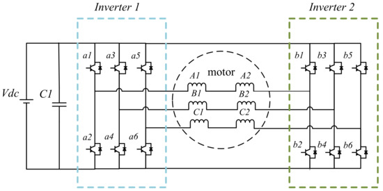
Figure 1.
Structure of open winding techniques.
Although the first approaches to this topic are relatively long ago, there is still significant recent research investigating the benefits of different topologies and winding configurations. In 2012, a winding-switching technique was proposed utilizing dual inverters and three thyristors in each phase utilized to extend the constant power speed ratio [5]. By using three thyristors to accumulate the induced electromotive force (EMF) for half of the windings, the speed range can be enlarged to 4-times the base speed. In [14], the OW topology has been altered to a configuration combining two switches, one thyristor, and basic fault tolerance. With the vector analysis, the authors verify that the extended ratio of the maximum speed to base speed is 3.732. Moreover, the experiments illustrate that the magnitude of the maximum line voltage achieves 1.732 times the value of the traditional control. The speed can be extended by a factor of 4.
Considering that the losses happen in the winding-switch circuit, a comparison among the topologies of three AC switches is carried out in [15]. Based on the analysis, a general conclusion can be drawn that the SCR-based winding switch has lower losses than the ones using IGBTs. To further optimize the circuit, a new approach was proposed with fewer AC switches; it avoids the short-circuit fault at the side of battery or other DC units [11]. With only five AC switches, the system is changed from serial to parallel at the different operation modes. Moreover, the system is tested with the anti-parallel thyristors, and the results verify the capacity of extension and the loss reduction, while the advisable switching time can be obtained in 5 ms.
The cascaded converters are widely used in microgrids, automotives, and aircrafts to decrease the DC-link harmonic current [16,17,18]. A two-cell interleaved DC-DC converter with two-level inverter PMSM control is investigated as one of the main models that aims to make a comparison with the proposed reconfigurable model. The schematic circuitry of a buck converter with VSC and PMSM is displayed in Figure 2. The PMSM operates as a generator in this model with the input rotor speed equal to 28,000 rpm, and the output voltage of VSI is 800 V. The buck DC-DC converter decreases the DC voltage to 540 V.
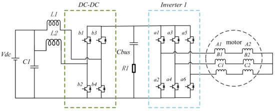
Figure 2.
Structure of the PMSM with DC-DC converter topologies.
Among recent publications on this topic, [19] introduces a method increasing the speed range without field weakening (FW), utilizing OW and two inverters. Besides the normal inverter, the second inverter is fed by a floating dc-link capacitor. The output voltage is enhanced with the extra floating bridge, and a terminal voltage higher than the supply voltage can be obtained. Moreover, these kinds of topologies can overcome the common-mode voltage problems that are inevitable in single-inverter topologies. However, this topology always requires the operation of both inverters, which reduces the efficiency during high-speed operation. Furthermore, the speed-range enhancement is not specified.
This paper proposed a new reconfigurable topology that contains one inverter with eight switches. The structure of the proposed topologies is shown in Figure 3 and Figure 4. When the speed is lower than the base speed, only S1, S2, and S3 are closed, and the PMSM operates as a traditional PMSM control with . When the speed of the generator is higher than the base speed, S1, S2, and S3 switch off and S4, S5, S6, S7, and S8 switch on, as shown in Figure 4. Half of the motor windings are operated in parallel, controlled by the same inverter.
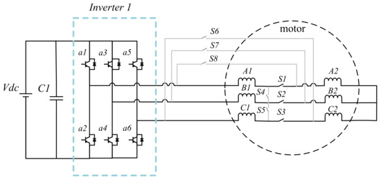
Figure 3.
Low-speed operation of RW.
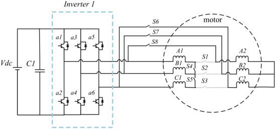
Figure 4.
High-speed operation of RW.
4. Simulation and Experimental Result
To validate the control system in a real-time implementation, a set of experiments on a hardware-in-the-loop (HiL) PLECS RTBox setup has been carried out as shown in Figure 5.
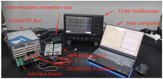
Figure 5.
Hardware-in-the-loop experiment setup.
In order to evaluate the performance of the proposed RW topology, four different models are compared under the same operating point. In the first model (M1), the generator is adjusted with the field-weakening control method to achieve the speed extension, which is two times the base speed. To compare the speed-extension ability of different models, only M1 uses field weakening as the main control strategy. In the second model (M2), the open-winding topology, which is described in Figure 1, is utilized to control the generator with two voltage-source inverters. In the third model (M3), a cascaded converter combines a two-cell interleaved converter with the machine-drive inverter to reduce the harmonic current ripple, as Figure 2 shows. The forth model (M4) is the proposed winding reconfiguration. The same machine model is used for all of the models, and all of the parameters are summarized in Table 1.

Table 1.
PMSM generator parameters.
To verify the high performance of the reconfigurable topology, several significant analysis results are summarized as listed in Table 2. The control method of each model is introduced, and the constant output power and constant input rotor speed are adopted as the main specifications. The three-phase current RMS value and dq axis currents can be obtained during the experiments. Electric power losses include the conduction losses, and the switching losses of all semiconductors and external switches are obtained with thermal analysis. Converter efficiency is defined by comparing the electric control system input power to its output power. redDifferent from the analytical equations, the simulation model considers the stator resistance and thus there’s a difference between mechanical and electrical power that is defined as stator losses. Motor efficiency is determined by comparing the input power of the generator to its output power. The experimental results of the four models, including the three-phase current, the d-axis, the q-axis current, and speed, are displayed in Figure 6, Figure 7, Figure 8 and Figure 9, respectively . Ts is the sampling period of the HIL experiments.
Table 2.
Experimental results of four models.
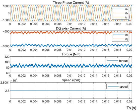
Figure 6.
Experimental results of Model 1.
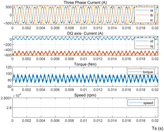
Figure 7.
Experimental results of Model 2.
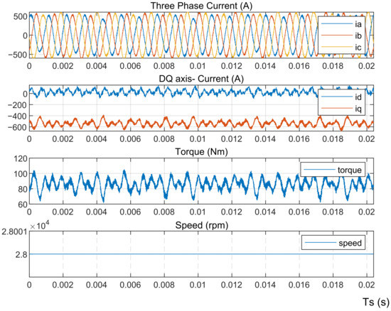
Figure 8.
Experimental results of Model 3.
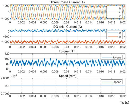
Figure 9.
Experimental results of Model 4.
With the same system power and rotor speed, M1 displays the highest three-phase current and the highest stator losses by using the demagnetizing component. Open winding topologies could achieve speed extension with a lower three-phase current and a non-demagnetizing current. However, two inverters also explore the controller size and increase the power losses to 7500 W. Moreover, although M3 shows the lowest losses and a current with similar efficiency to other models, there is one more extra dc-dc converter and two inductors in this configuration, leading to a larger size and higher costs. Additionally, Table 2 provides summaries of the converter efficiency, mechanical output, and motor efficiency. According to these analyses, the converter efficiency of M2 is lower than other models due to the huge power losses. Especially, M4 achieved the highest converter efficiency of 98.7% and motor efficiency of 99.89%. Consequently, to consider the overall effects of the system, the proposed winding reconfigurable topologies could achieve a speed extension with higher reliability.
5. Conclusions
This paper presents a comprehensive study of different methodologies for extending the speed range of the PMSM, where the variations are the winding structure of the PMSM and the power electronics for the drive. By keeping other parameters the same, all of the methodologies are validated through real-time simulation implemented by an HIL setup based on PLECS RTBox. It is observed the model M3 has the highest efficiency for the electrical machine and power electronics; however, the cost increases due to the addition of a large number of components. As a compromise, the model M4 where the electrical machine is featured with RW is promising considering the relatively low power losses, while the speed range is extended to meet the requirement without enabling FW, compared models M1 and M2. The built real-time simulation model and the obtained results can be used as a basis for further investigation of the effect of RW in different kinds of electrical machines, and of the efficiency of the power electronics drive using different kinds of power semiconductors.
Author Contributions
Methodology, G.M.; Software, X.Z.; Investigation, X.Z.; Writing—original draft, X.Z. and J.Y.; Writing—review & editing, J.Y., S.G., S.W. and G.B.; Supervision, S.G., C.G. and G.B. All authors have read and agreed to the published version of the manuscript.
Funding
This research was funded by Zhejiang Basic and Commonweal Programme of funder grant number LQ23E070002.
Data Availability Statement
Not applicable.
Conflicts of Interest
The authors declare no conflict of interest.
References
- Buticchi, G.; Wheeler, P.; Boroyevich, D. The More-Electric Aircraft and Beyond. Proc. IEEE 2022, 1–15. [Google Scholar] [CrossRef]
- Wheeler, P.; Bozhko, S. The More Electric Aircraft: Technology and challenges. IEEE Electrif. Mag. 2014, 2, 6–12. [Google Scholar] [CrossRef]
- Madonna, V.; Giangrande, P.; Galea, M. Electrical Power Generation in Aircraft: Review, Challenges, and Opportunities. IEEE Trans. Transp. Electrif. 2018, 4, 646–659. [Google Scholar] [CrossRef]
- Buticchi, G.; Bozhko, S.; Liserre, M.; Wheeler, P.; Al-Haddad, K. On-Board Microgrids for the More Electric Aircraft—Technology Review. IEEE Trans. Ind. Electron. 2019, 66, 5588–5599. [Google Scholar] [CrossRef]
- Hemmati, S.; Lipo, T.A. Field weakening of a surface mounted permanent magnet motor by winding switching. In Proceedings of the International Symposium on Power Electronics Power Electronics, Electrical Drives, Automation and Motion, Sorrento, Italy, 20–22 June 2012; pp. 736–740. [Google Scholar] [CrossRef]
- Morimoto, S.; Sanada, M.; Takeda, Y. Wide-speed operation of interior permanent magnet synchronous motors with high-performance current regulator. IEEE Trans. Ind. Appl. 1994, 30, 920–926. [Google Scholar] [CrossRef]
- Welchko, B.; Nagashima, J. The influence of topology selection on the design of EV/HEV propulsion systems. IEEE Power Electron. Lett. 2003, 1, 36–40. [Google Scholar] [CrossRef]
- Alosa, C.; Migliazza, G.; Immovilli, F.; Lorenzani, E. Reconfigurable Multi-Three-Phase Drive for Naval Rim-Driven Propulsion System. IEEE Trans. Ind. Appl. 2022, 58, 2075–2087. [Google Scholar] [CrossRef]
- Morimoto, S.; Takeda, Y.; Hirasa, T.; Taniguchi, K. Expansion of operating limits for permanent magnet motor by optimum flux-weakening. In Proceedings of the Conference Record of the IEEE Industry Applications Society Annual Meeting, San Diego, CA, USA, 1–5 October 1989; pp. 51–56. [Google Scholar] [CrossRef]
- Huang, H.; Chang, L. Electrical two-speed propulsion by motor winding switching and its control strategies for electric vehicles. IEEE Trans. Veh. Technol. 1999, 48, 607–618. [Google Scholar] [CrossRef]
- Tang, L.; Burress, T.; Pries, J. A reconfigurable-winding system for electric vehicle drive applications. In Proceedings of the 2017 IEEE Transportation Electrification Conference and Expo (ITEC), Chicago, IL, USA, 22–24 June 2017; pp. 656–661. [Google Scholar] [CrossRef]
- Nipp, E. Alternative to field-weakening of surface-mounted permanent-magnet motors for variable-speed drives. In Proceedings of the IAS ’95. Conference Record of the 1995 IEEE Industry Applications Conference Thirtieth IAS Annual Meeting, Orlando, FL, USA, 8–12 October 1995; Volume 1, pp. 191–198. [Google Scholar] [CrossRef]
- Takahashi, I.; Ohmori, Y. High-performance direct torque control of an induction motor. IEEE Trans. Ind. Appl. 1989, 25, 257–264. [Google Scholar] [CrossRef]
- Tian, B.; Zhang, Z.; Wei, J.; Lipo, T.A. Investigation of dual-inverter-fed drives for permanent magnet synchronous motor with winding switching. In Proceedings of the IECON 2014—40th Annual Conference of the IEEE Industrial Electronics Society, Dallas, TX, USA, 29 October 2014–1 November 2014; pp. 709–714. [Google Scholar] [CrossRef]
- Hao, L.; Namuduri, C.; Naik, S.M.; Freitas, C. High speed performance of PM machine with reconfigurable winding. In Proceedings of the 2015 IEEE Energy Conversion Congress and Exposition (ECCE), Montreal, QC, Canada, 20–24 September 2015; pp. 1840–1848. [Google Scholar] [CrossRef]
- Lu, X.; Qian, W.; Cao, D.; Peng, F.Z.; Liu, J. A carrier modulation method for minimizing the dc link capacitor current ripple of the HEV DC-DC converter and inverter systems. In Proceedings of the 2011 Twenty-Sixth Annual IEEE Applied Power Electronics Conference and Exposition (APEC), Fort Worth, TX, USA, 6–11 March 2011; pp. 800–807. [Google Scholar] [CrossRef]
- Okuda, T.; Urakabe, T.; Tsunoda, Y.; Kikunaga, T.; Iwata, A. Ripple Current Reduction in DC Link Capacitor by Harmonic Control of DC/DC Converter and PWM Inverter. IEEE Trans. Ind. Appl. 2009, 129, 144–149. [Google Scholar] [CrossRef]
- Choi, K.Y.; Kim, S.I.; Jung, S.M.; Kim, R.Y. Generalized Switching Modification Method Using Carrier Shift for DC-link Capacitor RMS Current Reduction in Real-Time Implementation. IEEE Trans. Ind. Electron. 2019, 66, 5992–6001. [Google Scholar] [CrossRef]
- Gerrits, T.; Wijnands, C.G.E.; Paulides, J.J.H.; Duarte, J.L. Dual voltage source inverter topology extending machine operating range. In Proceedings of the 2012 IEEE Energy Conversion Congress and Exposition (ECCE), Raleigh, NC, USA, 15–20 September 2012; pp. 2840–2846. [Google Scholar] [CrossRef]


Disclaimer/Publisher’s Note: The statements, opinions and data contained in all publications are solely those of the individual author(s) and contributor(s) and not of MDPI and/or the editor(s). MDPI and/or the editor(s) disclaim responsibility for any injury to people or property resulting from any ideas, methods, instructions or products referred to in the content. |
© 2023 by the authors. Licensee MDPI, Basel, Switzerland. This article is an open access article distributed under the terms and conditions of the Creative Commons Attribution (CC BY) license (https://creativecommons.org/licenses/by/4.0/).