Article

Underground Gravity Energy Storage: A Solution for Long-Term Energy Storage

1
International Institute for Applied Systems Analysis (IIASA), A-2361 Laxenburg, Austria
2
Faculty of Environmental Engineering, Wrocław University of Science and Technology, 50-370 Wrocław, Poland
3
School of Electrical and Electronic Engineering, North China Electric Power University, Beijing 102206, China
4
Institute of Environmental Protection and Development, Wrocław University of Environmental and Life Sciences, 50-375 Wrocław, Poland
5
Electric Sector Study Group, Federal University of Rio de Janeiro, Rio de Janeiro 21941-901, Brazil
6
Water, Energy, and Environmental Engineering Research Unit, University of Oulu, 90570 Oulu, Finland
7
Department of Civil Engineering, University North, 48000 Koprivnica, Croatia
8
Faculty of Life Sciences, Hamburg University of Applied Sciences, 20999 Hamburg, Germany
9
Center for Desert Agriculture, King Abdullah University of Science and Technology, East Thuwal 23955-6900, Saudi Arabia
*
Author to whom correspondence should be addressed.
Energies 2023, 16(2), 825; https://doi.org/10.3390/en16020825
Submission received: 29 November 2022 / Revised: 23 December 2022 / Accepted: 24 December 2022 / Published: 11 January 2023
(This article belongs to the Section C: Energy Economics and Policy)

Abstract

:
Low-carbon energy transitions taking place worldwide are primarily driven by the integration of renewable energy sources such as wind and solar power. These variable renewable energy (VRE) sources require energy storage options to match energy demand reliably at different time scales. This article suggests using a gravitational-based energy storage method by making use of decommissioned underground mines as storage reservoirs, using a vertical shaft and electric motor/generators for lifting and dumping large volumes of sand. The proposed technology, called Underground Gravity Energy Storage (UGES), can discharge electricity by lowering large volumes of sand into an underground mine through the mine shaft. When there is excess electrical energy in the grid, UGES can store electricity by elevating sand from the mine and depositing it in upper storage sites on top of the mine. Unlike battery energy storage, the energy storage medium of UGES is sand, which means the self-discharge rate of the system is zero, enabling ultra-long energy storage times. Furthermore, the use of sand as storage media alleviates any risk for contaminating underground water resources as opposed to an underground pumped hydro storage alternative. UGES offers weekly to pluriannual energy storage cycles with energy storage investment costs of about 1 to 10 USD/kWh. The technology is estimated to have a global energy storage potential of 7 to 70 TWh and can support sustainable development, mainly by providing seasonal energy storage services.

1. Introduction

The transition toward a sustainable and resilient energy system compliant with Paris climate targets requires large-scale storage of variable renewable energy, such as wind and solar, over different time periods from hours to weeks and seasons. Seasonal pumped hydro storage (SPHS) and hydrogen electrolysis (green hydrogen) are the two most envisioned alternatives for long-duration energy storage. However, the site specificity of SPHS and the high cost plus the low efficiency of green hydrogen have been an impetus for research on emerging solutions for long-duration energy storage, e.g., based on solid gravitational energy. Different geological and geographical locations can be considered for storing energy, such as mountains, oceans, underground caverns, or mines.
The number of closed or abandoned mines is challenging to estimate, but it is likely to be in the range of millions of sites globally. At least 50,000 of them are estimated to exist in Australia; over 550,000 have been found in the USA, including over 100,000 that pose a significant environmental risk; and over 10,000 are known to exist in Canada [1]. Old mines, exceptionally small mines and those located far from population centers, are rarely documented, and some abandoned mines are only found when an accident occurs. Figure 1a presents the current mining activity around the world. A list of the deepest underground mines worldwide is presented in [2].
The number of underground mines in the USA has shrunk from 2800 in 1983 to 500 in 2020 (Figure 1b). One important factor contributing to this reduction is the poor health conditions in mines due to air pollution and the risks involved in mining activities. The high number of underground mine closures increases the number of mines available for energy storage, as proposed in this paper.
Underground mines usually use lifts in mine shafts to transport the ore. Lifts are made up of several parts, as stated in [4]. The speed of gravity-stored weights is relatively slow (0.25–1 m/s), and the motor speed is generally 1500 rpm, therefore they do not match. Thus, gearboxes should be one of the necessary pieces of equipment for underground mines. Hence, the motors are being constructed with gears and regenerative brakes, which produce clean and safe electricity during descents, to achieve high and smooth acceleration while providing high-quality transportation services and maintaining a high overall energy efficiency [4]. The high-efficiency permanent-magnet synchronous gear motor (PMSGM) has been created for intelligent elevators. The PMSGM motor/performance generator’s characteristics have efficiencies higher than 92 percent [5,6,7]. Regenerative braking improves efficiency, mainly when the elevators operate with all cars wholly occupied. Regenerative braking system lifts are already applied in newly highly energy-efficient buildings. This allows the lifts to supply energy to the grid when descending with people or cargo. The efficiency of lifts can be improved by utilizing new technologies and best practices involving motors, regeneration converters, control software, counterweight optimization, or rope-free lifts [6].
Batteries and pumped-hydro storage (PHS) are the two most common electrical energy storage (EES) options for storing energy [8,9,10,11]. Batteries have a declining capital cost [12]. They will likely provide a cost-effective solution for intraday energy storage and ancillary services [13,14,15,16]. Due to the high cost of stored energy (150–200 $/MWh [12]), as well as in some situations, a high rate of losses and self-discharge during the day, the use of batteries to store energy in a weekly cycle might never become economically viable [17]. Additionally, the widespread use of batteries in power and mobility applications raises concerns about the sustainability and availability of resources, given the substantial reliance on materials for batteries [18,19]. PHS may store significant energy for weekly, monthly, or seasonal cycles [20,21,22,23,24]. For a large installed storage capacity, PHS plants are the only economically viable solution [25,26,27]. This is because the economy of scale lowers the cost of tunnels, pipelines, turbines, and generators per unit of generation capacity [28]. For instance, increasing the tunnel’s diameter results in a twofold increase in cost. It also quadruples the volume of water transported through it, increasing the plant’s capacity. As a result, PHS projects are more cost-effective in terms of installed capacity ($/MW), as demonstrated by [29].
The geospatial technology requirements significantly limit the potential for conventional PHS facilities. Although its global capacity is massive [30], individual projects often face unexpected local constraints that impede completion or even commencement. Therefore, the recent interest in underground PHS systems utilizing exploited or soon-to-be-closed subsurface mines is not unexpected. The attractiveness of using already existing underground structures is motivated by the prohibitive costs of excavation, materials-handling costs, risks related to mining, and time required. A prominent example is a recently proposed underground PHS system in Pyhäjärvi (Northern Ostrobothnia–Finland) in Europe’s deepest base metal mine (depth of 1444 m). Reports suggest that the project will be realized in two phases. Specifically, phase one presents a demonstrator and a full-scale system. Phase two reaches 75 MW of capacity [31,32]. The total storage capacity is estimated at 530 MWh, and round-trip efficiency should reach 77%. The generation with total capacity would last 7 h and a charge would last 9 h. However, the investment and exploitation of underground PHS are associated with additional risks, such as water pollution due to leakage [33], environmental impacts, and geological risks [34]. To overcome these issues, the water extracted from the mine can be treated, and the underground reservoirs would have to be sealed to reduce geological risks. A significant advantage is that such projects can be potentially realized near energy demand centers, and their spatial requirements are limited to the upper reservoir.
Solid gravitational energy storage, a technology for storing potential energy with solid materials at various elevations, is being funded by several companies and research projects [35]. Energy Vault stands out from the competition by erecting and deconstructing a tall tower composed of concrete blocks. The low head difference between the lower and top storage sites is a drawback of this method. The need for extreme accuracy while building the “concrete tower” might contribute to its erosion over time [36,37]. There are plans to transport a concrete mass from the lower to the upper storage location utilizing train tracks [38,39,40,41]. In addition to the need to build rail tracks, the weight of the train itself is similar to that of the concrete block, resulting in more significant energy losses. Compared to the steep decline suggested in this work, the slope of the train tracks similarly lowers the overall power output and efficiency [42]. The prospect of producing electricity using Electric Truck Hydropower is a comparable option that has recently drawn much interest [43]. Gravitricity proposes a similar alternative to the solution in this paper, storing potential energy using existing mining shafts [44,45,46,47,48]. The concept of storing energy in abandoned mine shafts is described in [49]. Storing energy in underground mines has 100 to 1000 times more energy storage capacity than Gravitricity because of the additional storage sites on the top and bottom of the mine. An overview of EES technologies, including the gravel energy storage technique [35,50] and others [51], which are similar to the concept described in this research is published in [52]. Other than hydrogen and other synthetic fuels with relatively low AC-to-AC efficiency with high capital costs and SPHS, limited to mountainous regions, there is no viable technology for long-term energy storage.
This research proposes a novel method to manage and exploit decommissioned underground mines called Underground Gravity Energy Storage (UGES) as a potential filler for this gap. It uses decommissioned underground mines to store energy by filling them up with sand. The UGES design proposed in this paper is considerably different from what has been proposed in the literature and industry, which has not been patented. The remaining content of this paper is structured as follows. Section 2 discusses the methods, while Section 3 presents the results. Section 4 discusses the proposed technology, and Section 5 concludes the paper.

2. Materials and Methods

The methodology used to evaluate UGES is presented in Figure 2. In Step 1, the technology is described, the system components are defined, the energy storage process is explained, and gravity energy storage equations are presented. Step 2 consists of designing the UGES project, selecting the material for storing potential energy, estimating energy storage and power capacity, and running a case study for a mine close to Johannesburg, South Africa. Step 3 analyses the potential for the technology. It estimates the costs of the system, the energy storage cycles, and the global energy storage potential of UGES. It then describes the possibility of using UGES as a carbon storage alternative and other technical characteristics.

Underground Gravity Energy Storage (UGES)

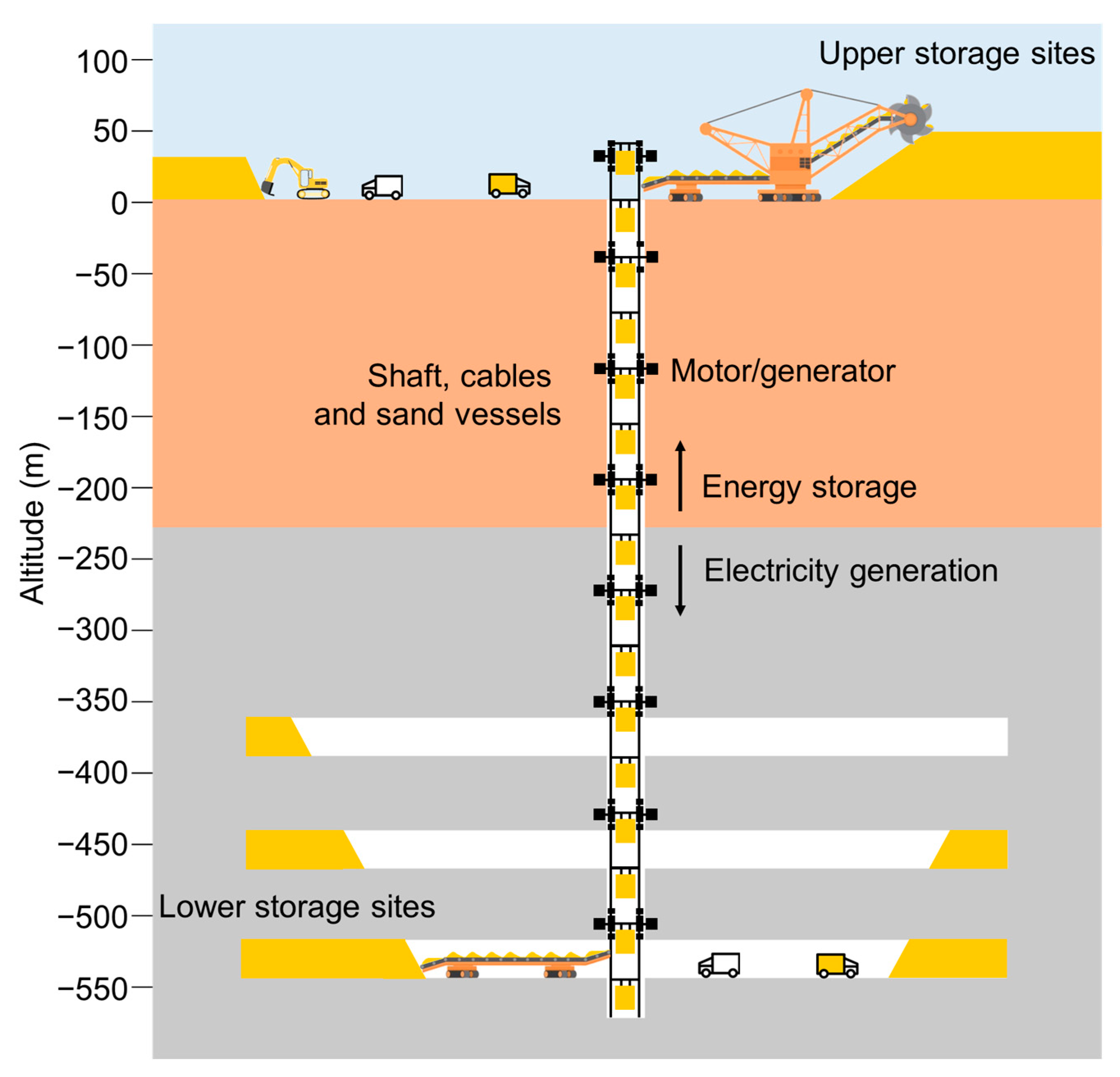
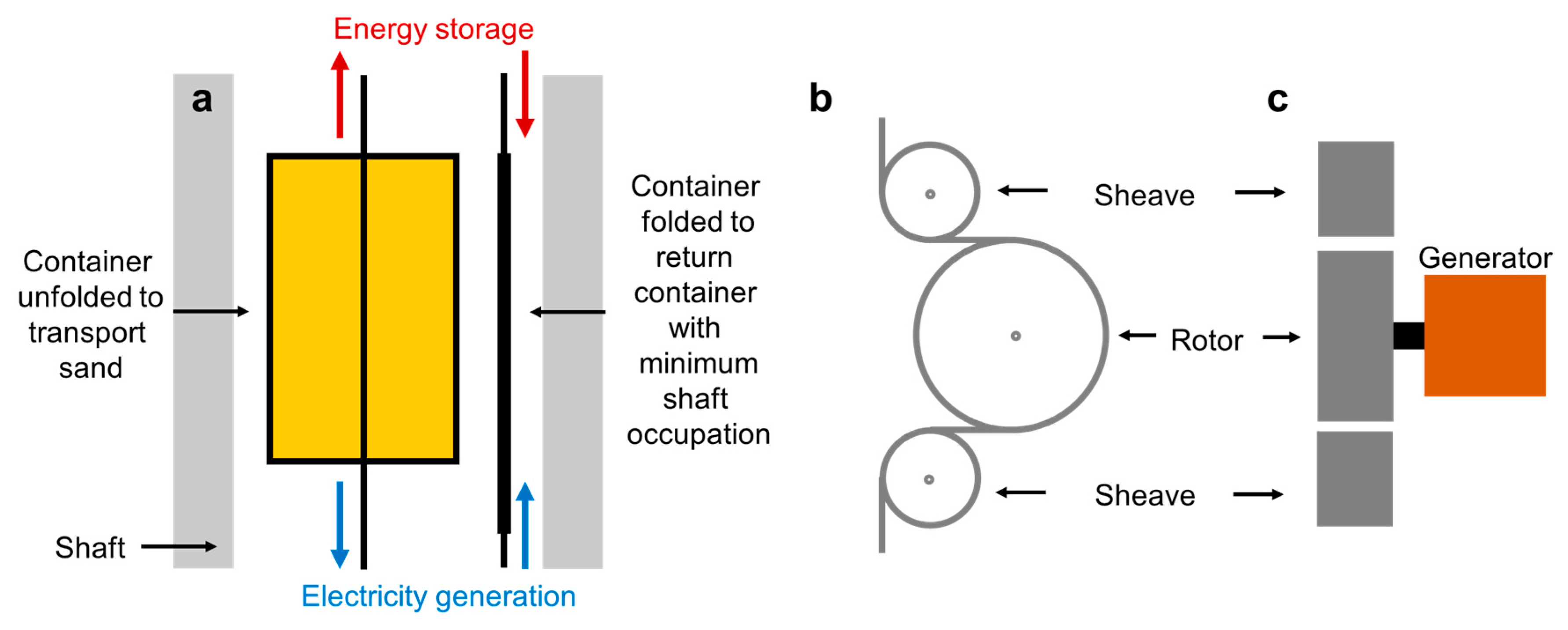
UGES is a gravitational energy storage technology that consists of filling an underground mine with sand to generate electricity when the cost of electricity is high and then removing the sand from the mine to store energy when electricity is cheap. The main components of UGES are the shaft, motor/generator, upper and lower storage sites, and mining equipment (Figure 3). The UGES shaft has variable depths and diameters. The deeper and broader the mine shaft, the more power can be extracted from the plant. In addition, the more volume in the mine, the higher the plant’s energy storage capacity. To maximize power capacity, the sand containers in the shaft occupy approximately 50% of the shaft’s volume. The other 50% of space is required for filling and emptying the containers with sand. To reduce the costs and number of cables to support the sand containers and the forces exerted on the motor/generator, we propose several motors/generators throughout the shaft. The containers in Figure 4 are independent, i.e., each module can be put into operation or removed independently (to complete loading and unloading), ensuring that the system does not stop due to the putting in or removal of carriers. In addition to independence, the container must enable the rapid loading and unloading of heavy objects (sand). Thus, we consider setting up loading stations, which can be similar to ski lift stations.
The containers applied in the shaft are foldable to optimize the utilization of the shaft. During storage mode, the sand is removed from the container on the shaft’s top and then is returned to the bottom of the shaft to be filled again. The container is folded to occupy the least space on the shaft, as shown in Figure 4. Foldable containers that are not completely sealed could leak sand during operation. This would cause energy loss and damage equipment in the mine or block the shaft. To mitigate this problem, we propose foldable containers with inner bags as carriers, where the bags act as liners for the foldable containers. This results in a space-saving foldable carrier while preventing the safety hazard of sand leakage.
The motor/generators are installed on both sides of the mine shaft, as shown in Figure 3. They should be installed on top of the filling and empty stations to minimize the risk of damage. The total power capacity of the plant consists of the sum of the capacity of all motors/generators. Other advantages of having several motors/generators are that motors/generators with a small capacity are easy to find in the market and are inexpensive. It should be noted that the motors in Figure 4 are electrically connected in parallel to ensure the independence of each motor input and removal. If one motor/generator brakes or requires maintenance, the others can continue operation. Depending on the power requirements for energy storage, the system can alter the lift’s speed. The lift can raise its speed if the power requirements are high, but it might lower the system’s overall efficiency.
The system should be designed to provide a constant power supply. However, due to possible power fluctuation as a result of dropping and loading of the sand to the system, a partial loss of torque and generation is expected. To resolve this issue, the proposed UGES design presented in this paper has multiple motors/generators to ensure a high degree of continuity in the generation profile. We expect slight deviations in the continuous supply, of −10 to +10%, which needs to be balanced with grid balancing measures or additional short-term storage onsite.
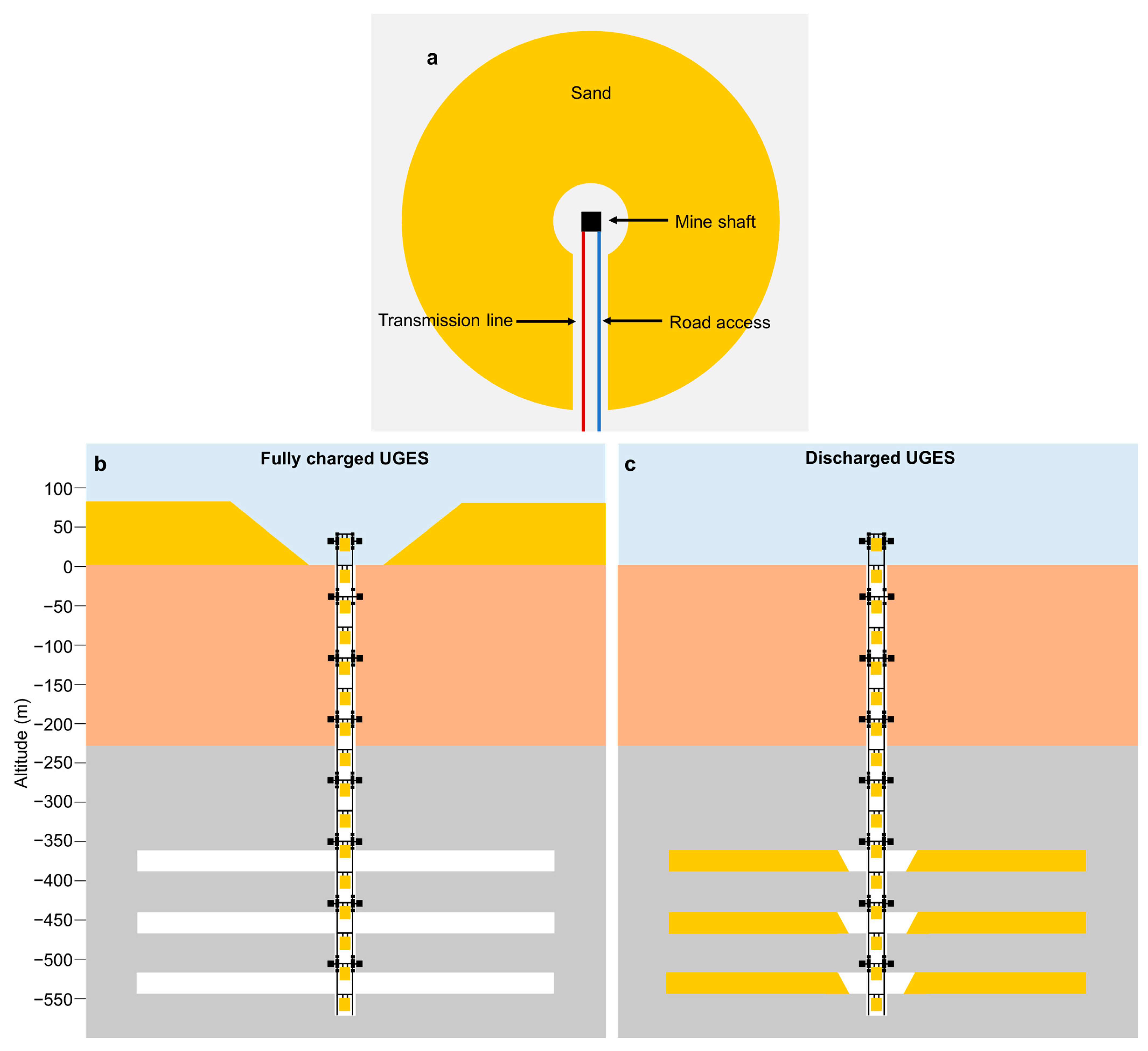
The upper storage site of a UGES plant is designed to store as much sand as possible on the surface surrounding the mine shaft to minimize the energy required to store the sand on the surface. We propose a circular sand pile surrounding the mine shaft, as shown in Figure 5a. The sand pile’s outer diameter will depend on the availability and cost of land. If the land cost is high, the sand pile can rise vertically as the trucks dump the sand on top of the sand pile. The sand pile can reach heights of 50 m or more. Figure 5b shows the upper storage site filled up and the UGES plant fully charged. The lower storage site consists of filling the entire underground mine with sand. The mine is filled from its extremes until the channels reach its shaft. Figure 5c presents the lower storage site filled up, and the UGES plant discharged.
The mining equipment is essential to managing the sand in the upper and lower storage sites. They consist of dump trucks, conveyor booms, bucket wheel excavators, and soil compactors. Dump trucks or conveyor belts transport the sand from the mine shaft to the storage sites and back. The dump truck should be electric. This is because they can recharge their batteries while driving down sand piles or tunnels in the underground mine, increasing the efficiency of the UGES plant. Conveyor belts can also create a sand pile around the mine shaft. Conveyor belts should also generate electricity when lowering weights. The excavators and bucket wheel excavators extract sand from the upper and lower storage sites to load the dump trucks or conveyor belts. The soil compactor is applied to the sand piles to allow dump trucks to drive in the sand piles and increase their stability.
Equation (1) represents the quantity of energy stored, which is proportional to (i) the mass of the energy being stored; (ii) the height difference between the lower and upper storage sites; and (iii) the system’s overall efficiency. The system’s energy storage capacity increases as the head difference and storage mass increase.
E = m × h × g × e
where E is the energy stored in the containers (in Joules), m is their mass (in kilograms), h is the average height difference between the upper and lower storage sites (in meters), g is the gravitational acceleration (in meters per second), and e is the system’s efficiency, which is assumed to be 80% based on [53].
Equation (2) can compute the power produced by the UGES plant. The power of a UGES plant depends mainly on the shaft’s dimensions, the sand’s speed, the number of containers in the shaft, and the equipment’s efficiency.
P = H × e × ( ρ × K l × A × H ) × g H V × 10 6
where H is mine depth (in meters); e is the efficiency (gravitational potential energy to electrical energy), assumed to be 90%; ρ is the density of the sand, assumed to be 1600 kg/m3; K l is the load factor, assumed to be 90%; A is the area of container (in m2); g is the gravitational acceleration (in meters per second); V is the carrier rated operating speed; and 10 6 is the conversion factor (Watt to Mega Watt).

3. Results

The amount of usable space will determine the suggested design’s storage medium in the upper storage site (surface) and the lower storage site (underground), which is proportional to the energy storage potential of the mine, the demand for the energy storage service, and the energy storage costs. For instance, a solution including a sand and water mixture can be appropriate due to its low cost. However, if the mine is small and the demand for energy storage is high, materials with a higher density may be used if the additional cost of the material permits. The densities and prices of various storage mediums have been compared [54,55,56,57,58].
The paper investigates UGES projects with 4,000,000 and 40,000,000 tons of sand. Assuming a sand density of 1600 kg/m3 and that the cone-shaped sand pile has an average height of 50 m, the area required is 0.15 and 1.5 km2. Table 1 compares various operational setups for UGES (the usual weight limit applied in conventional lifts is shown in Table 1). Concerning the mine storage capacity, the number of storage containers varies greatly. Assuming that the lifts in the mine have an average power generation capacity of 10 MW, the storage cycle in days is projected to be (87.2/24/10 * 1000 = 363.3). The plant’s capacity factor is poor because it spends half of the time storing energy and half of the time producing electricity.
Additionally, to generate electricity, the lift must travel up and down. The electricity generation capacity factor is 35% if the system is used at a 70% capacity factor. The energy storage capacity of a mine with 4,000,000 tons of sand and a 200 m average height difference is 1.74 GWh (4,000,000 × 1000 × 200 × 0.8 × 9.81/1000/1000/1000/60/60 = 1.74 GWh), which is slightly smaller than a usual daily pumped storage plant [59]. Higher average height differences in the UGES plant result in longer storage cycles and greater energy storage capacity. As shown in Table 1, various operational configurations could lead to energy storage cycles of a week, a month, or a year. Since batteries can more reliably, affordably, and efficiently supply short-term energy storage, the UGES design and operation should concentrate on long-term storage cycles (weekly, monthly, or yearly). However, the UGES could also supplement short-term energy storage on emergent occasions.
The power capacity of UGES plants depends on the amount of sand that can be lowered each time. This varies with the shaft depth, dimensions, speed, and density. The density is assumed to be 1600 kg/m3. Table 2 presents the power capacity of UGES projects. As can be seen, a project with a 200-meter depth with container dimensions of 1 m × 1 m and a speed of 0.25 m/s has a power capacity of 0.35 MW of electricity.
On the other hand, a project 1000 m deep with container dimensions of 4 × 4 at a speed of 1.0 m/s has a power capacity of 113 MW. This power capacity is similar to a small PHS plant. PHS plants have higher power capacities because of the larger tunnel diameters (10 m), larger velocities (4–6 m/s), and the whole tunnel being filled with water.
To display the operation of a UGES plant, we propose using a solar power plant with 1.35 GW and a UGES plant with 100 GWh storage capacity in the TauTona mine to meet 1% of the demand for electricity in South Africa [60]. The TauTona mine and solar power plant are located 50 km from Johannesburg, South Africa, with the coordinates of −26.4160 latitude and 27.4274 longitude, as presented in Figure 6a. Data from the Renewable Ninja website create the location’s solar generation profile [61]. The minimum power capacity required to supply the energy described in Figure 6a is 36 MW. The proposed UGES plant has an average depth of 1150 m and 40,000,000 tons of sand and operates with a speed of 0.25 m/s. Figure 6b illustrates how the UGES plant is intended to store energy in seasonal cycles. The short-term energy storage cycles are not described and are assumed to be performed with other energy storage alternatives, such as batteries and pumped storage. Besides providing seasonal storage generation, the UGES plant can also generate power during exceptionally hot days.
This study supposes that the mine shaft and the underground tunnels are already in place. However, there is still the need to buy the sand and the mining auxiliary equipment and install the cables, moto/generators, and foldable containers. This paper does not consider the additional charge of renting the mine and its top to store the containers and sand. The costs of UGES components are described in Table 3. A mine with 40,000,000 tons of sand and an average height difference of 1000 m is being utilized to demonstrate the system’s cost. A 1.6 USD/kWh price tag is projected for energy storage. The cost of storing energy with UGES decreases with an increase in the height difference between the lower and upper storage locations. Table 4 presents the UGES energy storage costs and power capacities at different depths. It should be noted that because natural underground mine caverns are irregular, there may be associated remediation costs which are not considered in this study due to the difficulty of assessment.

4. Discussion

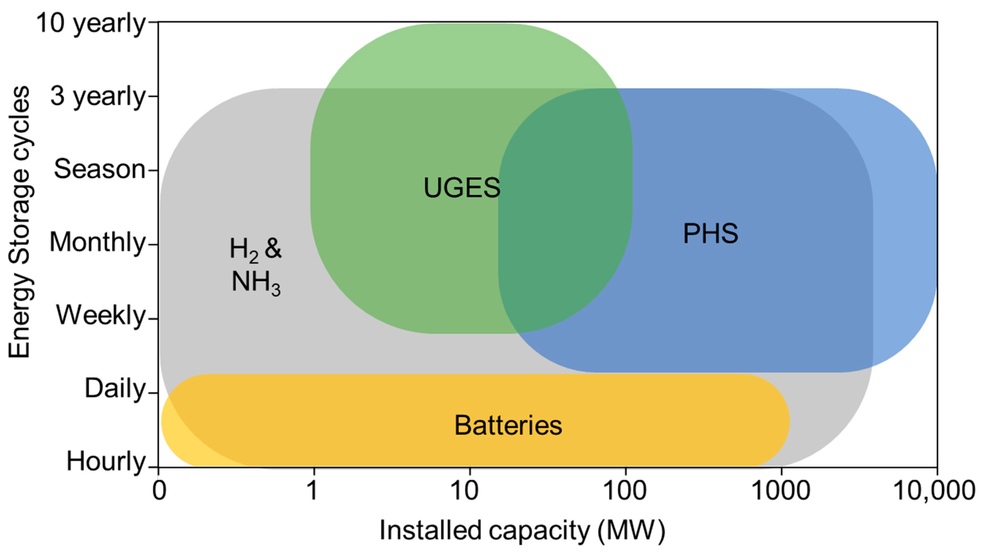
The main technical limitation of UGES is the high power capacity (MW), which involves the shaft lift and equipment to transport the sand in the upper and lower storage sites. The system’s main benefit is the low energy storage costs (MWh), which involve the cost of the sand and the land required to store the sand in the upper storage site. Thus, UGES is proposed for weekly, monthly, seasonal and pluriannual energy storage cycles with small power requirements. The comparison between the energy storage cycle and installed capacity between UGES with batteries, PHS, ammonia, and hydrogen is shown in Figure 7. The limitations of batteries for temporary energy solutions are highlighted in this figure, together with long-term energy storage options [62]. See [63,64,65,66,67,68,69] for further information on technologies with short storage cycles. The findings can help energy planners and decision-makers comprehend this storage system’s potential costs and benefits compared to other options.
UGES is attractive for generating or storing a stable amount of energy in weekly, monthly, or seasonal and pluriannual cycles due to their low energy storage cost and high power cost, as shown in Table 5. UGES have similar energy storage costs to PHS but higher installed capacity costs. Given the low installed capacity cost of batteries, a UGES plant should be connected to battery storage so that the plant can provide short- and long-term energy storage services cheaply.
Comparing UGES with underground pumped hydropower storage, the latter technology should be given priority due to its lower investment and operational costs. However, if underground pumped hydropower storage cannot be applied due to lack of area for the upper reservoir, lack of water in water-scarce regions, uncontrollable groundwater and surface water pollution, or due to structural impairment of the mine, UGES should be considered. UGES should also be used if the focus is long-term energy storage, such as seasonal, 3 or 10 yearly energy storage cycles, as underground pumped hydropower storage results in significant losses due to evaporation.
The Global Coal Mine Tracker [71], a database containing slightly more than three thousand records, was used to estimate the global potential for UGES. The database represents entries related only to coal mines. This sample is significantly smaller than the numbers quoted in the introduction. However, a detailed, global and open database is currently unavailable. We motivate the selection of coal mines based on the following argumentation. The world is transforming its energy system, halving coal extraction for energy-related purposes. At the same time, UGES can provide an alternative source of revenue to the people working in the mines and the community to overcome one of the critical barriers in energy transitions, i.e., the loss of jobs and the restructuring of the incumbent industry.
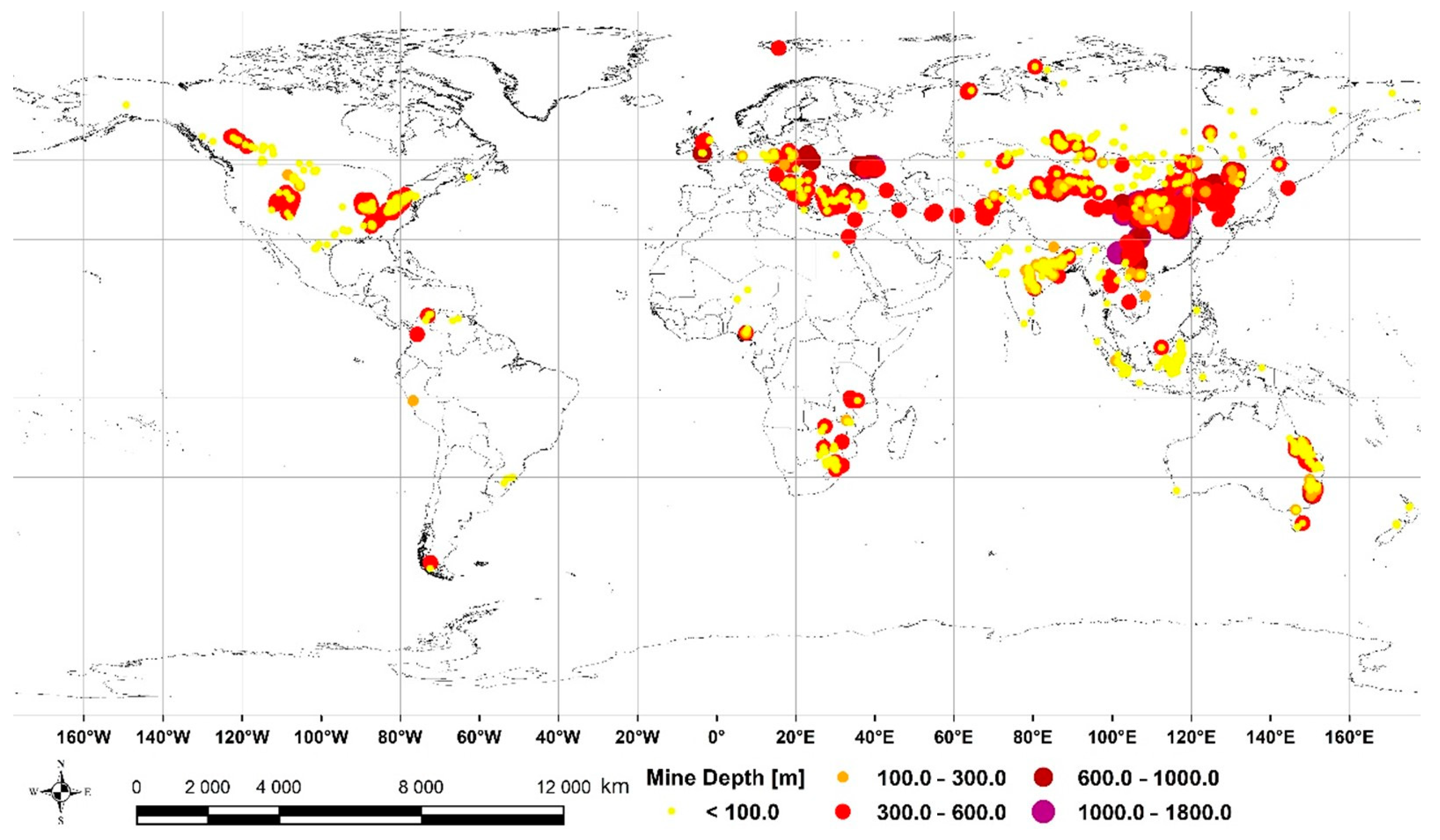
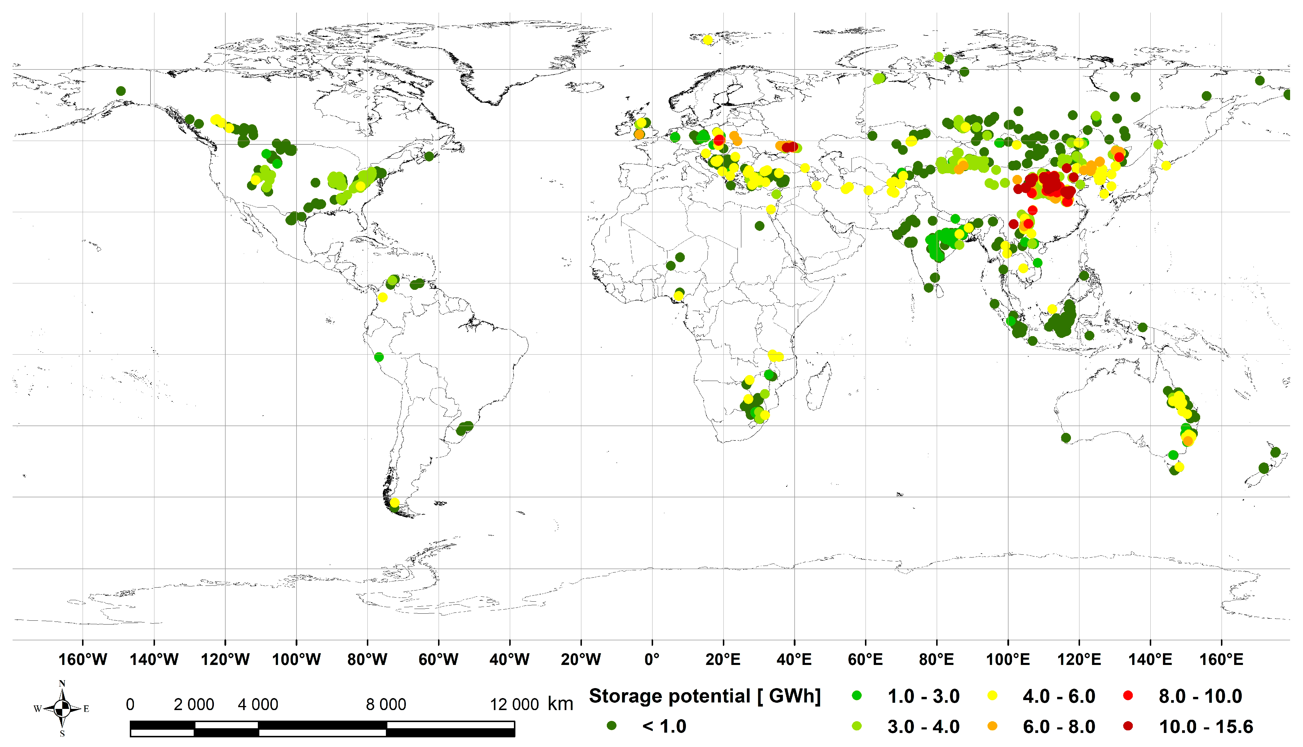
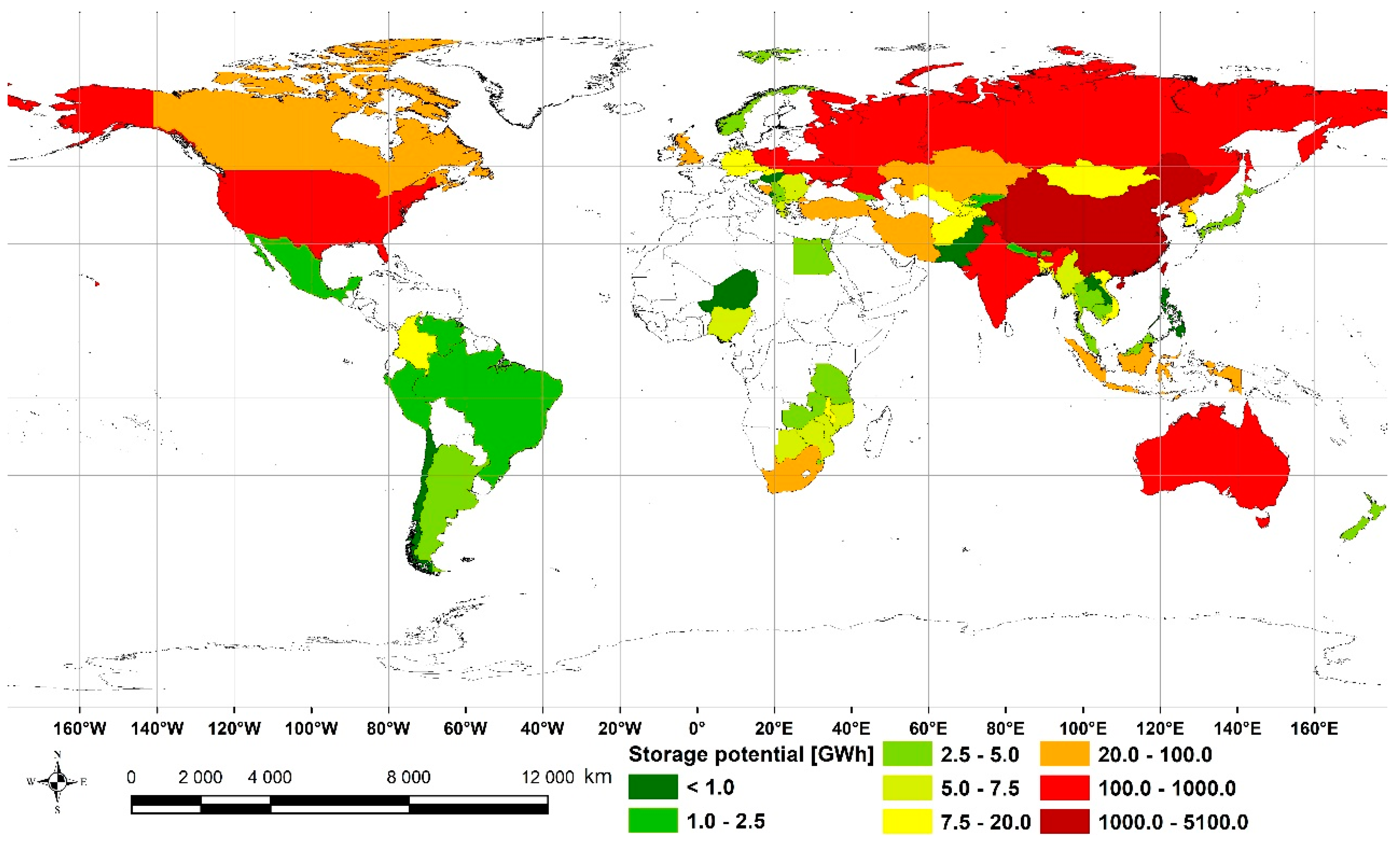
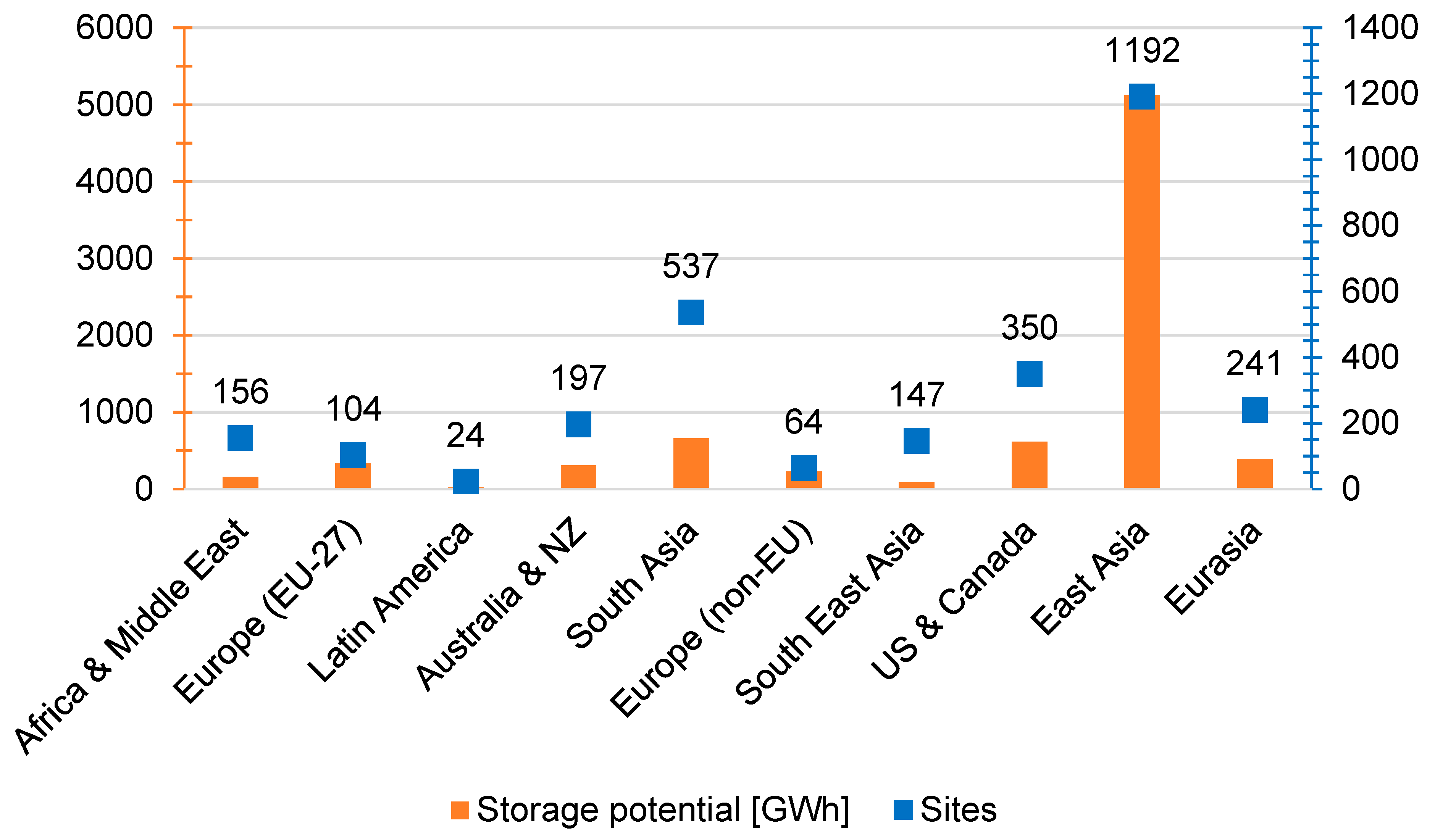
Out of the three thousand entries in the database, 55% are underground mines, 41% are surface/open-pit mines, and the remainder are hybrid underground/surface mines. Mines have various statuses: operating, shelved, proposed, canceled, mothballed, and closed. For global potential estimation, we have considered all of them apart from the canceled ones (26 projects were marked as such). The majority of sites are located in East Asia (39.6%), followed by South Asia (17.8%) and the US and Canada (11.6%). The average underground mine’s depth is roughly 500 m. Based on the calculation presented in the Results section and assuming 4,000,000 tons of sand for the UGES plant, we have estimated the global potential to be slightly above 7 TWh. China is the only country with a TWh scale potential (5041 GWh storage potential), whereas India and the USA have 649 GWh and 579 GWh, respectively. The potential of Europe (both EU zone and non-EU zone) exceeds 0.55 TWh. Increasing the capacity to 40,000,000 tons of sand increases the global potential to 70 TWh. It must be stressed that the results presented here represent pure theoretical potential, and each site requires a detailed case-study level analysis. The spatial distribution of underground mines and their depths is presented in Figure 8. Figure 9 presents the storage potential of the mines. Figure 10 presents the UGES energy storage potential per country. Figure 11 presents the number of underground mines per energy storage potential. Figure 12 presents the energy storage potential and number of sites per major global region. This study did not (and could not) consider all mine specifics, but it gives a good approximation of underground mines generally.
Gravity energy storage requires a significant amount of weight for its applications. Instead of using sand as the storage material, it can use carbon-based materials. These can be logs of wood, sawdust, or wood clip blocks. The higher the density, the better. An outer layer should be added to the wood to avoid its decomposing. Care should be taken to prevent fires in the mines, mainly when the mine is deep, dry, and hot. Assuming that 50% of the weight of wood is carbon [72], 1 kg of wood stores 3.6 kg of CO2. Table 6 presents the amount of CO2 sequestered and stored in UGES plants with 72,000,000 tons of wood. Assuming a coal plant with a CO2 emission of 900 kg/MWh, the UGES plant captures and stores the CO2 equivalent to a 1 GW power plant generating electricity at full capacity for 33.5 years. Other carbon-based materials with high density are presented in [73].
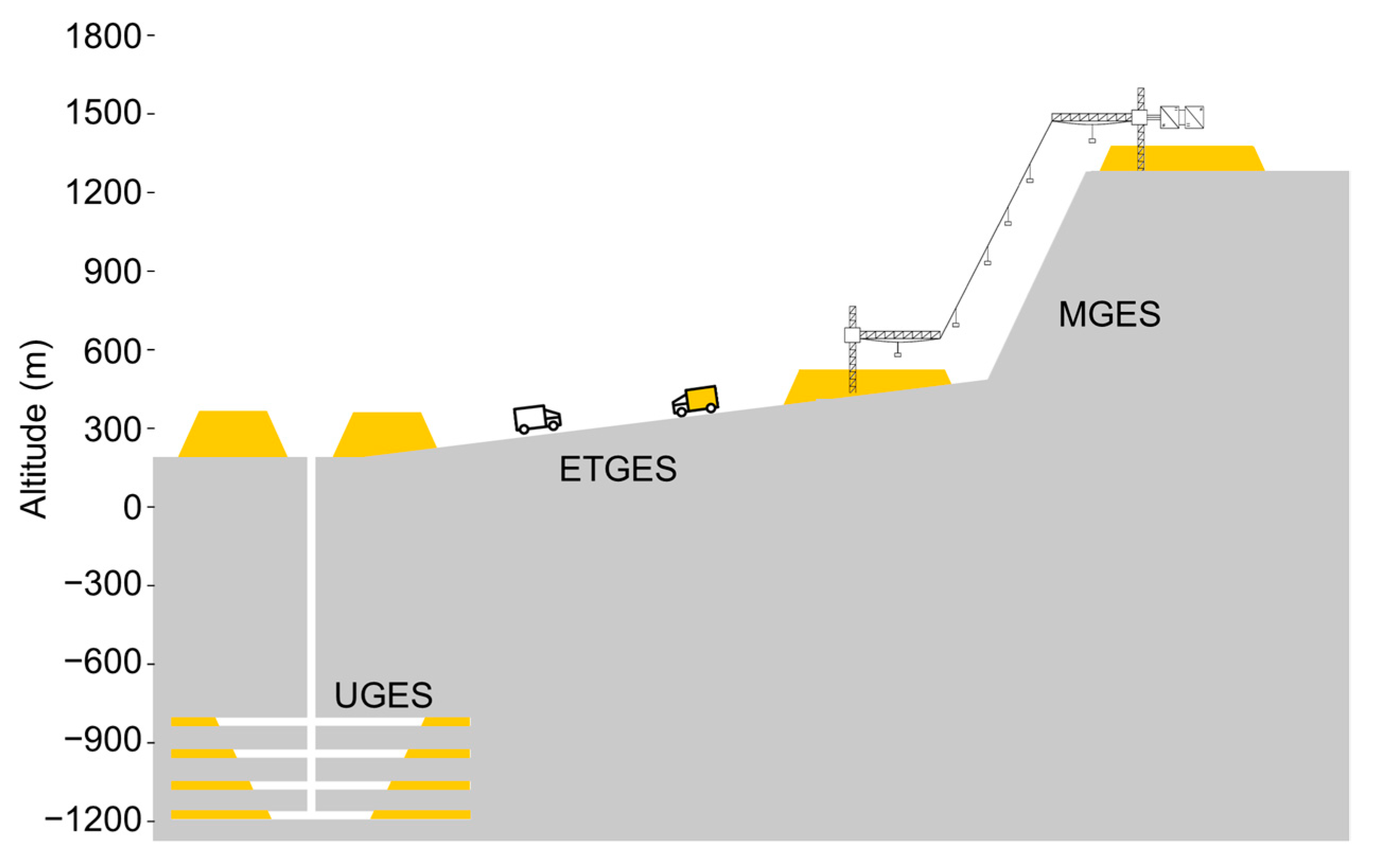
Another advantage of UGES is that the operation of an energy storage facility on the mine would reduce the decommissioned mine’s monitoring costs. Table 7 compares different gravitational energy storage technologies with UGES. Another option that might be interesting is to combine several gravity energy storage technologies, as shown in Figure 13. Note that the depth of the underground mine can be significantly greater than the proposed values presented in this paper, as shown in [2].
In cold regions, UGES can be combined with geothermal energy. This is because the temperature of the mines can reach 60 °C or more, while the outside temperature is below 0 °C. In these cases, containers filled with phase change material (PCM) can be used instead of sand. The PCM material would melt in the mine with the high temperatures and provide heating services to customers on the surface surrounding the mine. The combination of the two services can significantly reduce the cost of UGES.

5. Conclusions

In light of the findings of this study, to produce a modest but constant amount of energy for a long time, UGES could be designed to store energy over weekly, monthly or seasonal scales, depending on the demand for energy storage. To offset the short-term changes in electricity consumption of solar and wind generation, this modest but consistent electricity generation might be supplemented with other storage technologies, such as batteries and PHS. The cost of installed energy storage for UGES is estimated in this study to vary from 1.0–10.0 USD/kWh, assuming an average height difference between the upper and lower storage sites of 1500 and 200 m, respectively. The project is less expensive the more significant the height difference. The power generation capacity varies with the mine’s depths, the mine shaft’s diameter, and the sand moving speed. This paper proposed constructing several motors/generators along the shaft to reduce the cables’ costs and allow using smaller, more common/affordable motors/generators. The system’s technical lifespan can range from 20 to 30 years. The technology’s storage potential ranges from 7 to 70 TWh globally, with most of this potential concentrated in China, India, the USA, and Russia. A precise description of the UGES system performance is outside this paper’s scope. We propose a more detailed analysis of the system’s performance and efficiency for future work. UGES is a particularly interesting technology for long-term energy storage to reduce seasonal fluctuations in electricity demand and wind and solar generation.

Author Contributions

Conceptualization, J.D.H., B.Z. and K.R.; methodology, J.D.H.; software, P.B.D.; validation, J.J.; formal analysis, B.Z.; investigation, E.R.P. and B.Đ.; resources, K.R.; data curation, R.B. and B.Đ.; writing—original draft preparation, J.D.H. and W.T.; writing—review and editing, B.Z.; visualization, W.L.F.; supervision, Y.W.; project administration, B.v.R. All authors have contributed to drafting the manuscript and/or reviewing the final version. All authors have read and agreed to the published version of the manuscript.

Funding

Funding from the State Grid Brazil Holdings via the Brazilian Agency of Electric Energy R&D program. Project title: “Framework Development for Pumped Storage Hydro Power Projects”. Funding number: PD-05018-0120/2020.

Data Availability Statement

Data available upon request.

Conflicts of Interest

The authors declare that they have no conflict of interest.

References

  1. Global Challenges Abandoned Mines: The Scars of the Past. Available online: https://globalchallenges.ch/issue/6/abandoned-mines-the-scars-of-the-past/ (accessed on 1 January 2023).
  2. Wikipedia List of Deepest Mines. Available online: https://en.wikipedia.org/wiki/List_of_deepest_mines (accessed on 1 January 2023).
  3. Centre of Disease Control and Prevention Number of Active Underground Mines by Sector and Year, 1983-2020. 2021. Available online: https://wwwn.cdc.gov/niosh-mining/MMWC/Mine (accessed on 1 January 2023).
  4. ABCO Elevator Traction Elevators 101. Available online: https://abcoelevator.com/elevator-types-components/traction-elevators-101/ (accessed on 1 January 2023).
  5. Hwang, J.; Liu, C.; Chen, P. Design of Permanent-Magnet Synchronous Gear Motor with High Efficiency for Elevators. In Proceedings of the 2012 IEEE Third International Conference on Sustainable Energy Technologies (ICSET), Kathmandu, Nepal, 24–27 September 2012; pp. 205–210. [Google Scholar]
  6. Al-Kodmany, K. Tall Buildings and Elevators: A Review of Recent Technological Advances. Buildings 2015, 5, 1070–1104. [Google Scholar] [CrossRef] [Green Version]
  7. Mohaney, S.; Shah, M. Emerging Trends in Vertical Elevating System. Int. J. Eng. Manag. Res. IJEMR 2015, 5, 51–56. [Google Scholar]
  8. Groppi, D.; Garcia, D.; Basso, G.; Cumo, F.; De Santoli, L. Analysing Economic and Environmental Sustainability Related to the Use of Battery and Hydrogen Energy Storages for Increasing the Energy Independence of Small Islands. Energy Convers. Manag. 2018, 177, 64–76. [Google Scholar] [CrossRef]
  9. Hunt, J.D.; Zakeri, B.; Leal Filho, W.; Schneider, P.S.; de Assis Brasil Weber, N.; Vieira, L.W.; Ermel, C.; de Castro, N.J.; Barbosa, P.S.F.; Nascimento, A.; et al. Swimming Pool Thermal Energy Storage, an Alternative for Distributed Cooling Energy Storage. Energy Convers. Manag. 2021, 230, 113796. [Google Scholar] [CrossRef]
  10. Hunt, J.D.; Weber, N.d.A.B.; Zakeri, B.; Diaby, A.T.; Byrne, P.; Filho, W.L.; Schneider, P.S. Deep Seawater Cooling and Desalination: Combining Seawater Air Conditioning and Desalination. Sustain. Cities Soc. 2021, 74, 103257. [Google Scholar] [CrossRef]
  11. Hunt, J.D.; Zakeri, B.; Nascimento, A.; Garnier, B.; Pereira, M.G.; Bellezoni, R.A.; de Assis Brasil Weber, N.; Schneider, P.S.; Machado, P.P.B.; Ramos, D.S. High Velocity Seawater Air-Conditioning with Thermal Energy Storage and Its Operation with Intermittent Renewable Energies. Energy Effic. 2020, 13, 1825–1840. [Google Scholar] [CrossRef]
  12. Schmidt, O.; Melchior, S.; Hawkes, A.; Staffell, I. Projecting the Future Levelized Cost of Electricity Storage Technologies. Joule 2019, 3, 81–100. [Google Scholar] [CrossRef] [Green Version]
  13. Yang, Y.; Bremner, S.; Menictas, C.; Kay, M. Battery Energy Storage System Size Determination in Renewable Energy Systems: A Review. Renew. Sustain. Energy Rev. 2018, 91, 109–125. [Google Scholar] [CrossRef]
  14. Lorenzi, G.; da Silva Vieira, R.; Silva, C.; Martin, A. Techno-Economic Analysis of Utility-Scale Energy Storage in Island Settings. J. Energy Storage 2019, 21, 691–705. [Google Scholar] [CrossRef]
  15. Lazaroiu, G.; Ciupageanu, D. Multi-Criteria Decision Making in Sustainable Renewable Energy Systems. In Proceedings of the International Multidisciplinary Scientific GeoConference SGEM2019, Albena, Bulgaria, 28 June–6 July 2019. [Google Scholar]
  16. Ferreira, H.L.; Garde, R.; Fulli, G.; Kling, W.; Lopes, J.P. Characterisation of Electrical Energy Storage Technologies. Energy 2013, 53, 288–298. [Google Scholar] [CrossRef] [Green Version]
  17. Hajiaghasi, S.; Salemnia, A.; Hamzeh, M. Hybrid Energy Storage System for Microgrids Applications: A Review. J. Energy Storage 2019, 21, 543–570. [Google Scholar] [CrossRef]
  18. Wadia, C.; Albertus, P.; Srinivasan, V. Resource Constraints on the Battery Energy Storage Potential for Grid and Transportation Applications. J. Power Sources 2011, 196, 1593–1598. [Google Scholar] [CrossRef] [Green Version]
  19. Taibi, E.; del Valle, C.; Howells, M. Strategies for Solar and Wind Integration by Leveraging Flexibility from Electric Vehicles: The Barbados Case Study. Energy 2018, 164, 65–78. [Google Scholar] [CrossRef]
  20. Hunt, J.D.; Freitas, M.A.V.D.; Pereira Junior, A.O. A Review of Seasonal Pumped-Storage Combined with Dams in Cascade in Brazil. Renew. Sustain. Energy Rev. 2017, 70, 385–398. [Google Scholar] [CrossRef]
  21. Hunt, J.D.; Falchetta, G.; Parkinson, S.; Vinca, A.; Zakeri, B.; Byers, E.; Jurasz, J.; Quaranta, E.; Grenier, E.; Pereira Junior, A.O.; et al. Hydropower and Seasonal Pumped Hydropower Storage in the Indus Basin:Pros and Cons. J. Energy Storage 2021, 41, 102916. [Google Scholar] [CrossRef]
  22. Hunt, J.; Byers, E.; Wada, Y.; Parkinson, S.; Gernaat, D.; Langan, S.; Vuuren, D.; Riahi, K. Global Resource Potential of Seasonal Pumped-Storage for Energy and Water Storage. Nat. Commun. 2020, 11, 947. [Google Scholar] [CrossRef] [PubMed] [Green Version]
  23. Hunt, J.D.; Freitas, M.A.V.; Pereira Junior, A.O. Enhanced-Pumped-Storage: Combining Pumped-Storage in a Yearly Storage Cycle with Dams in Cascade in Brazil. Energy 2014, 78, 513–523. [Google Scholar] [CrossRef]
  24. Hunt, J.D.; Guillot, V.; de Freitas, M.A.V.; Solari, R.S.E. Energy Crop Storage: An Alternative to Resolve the Problem of Unpredictable Hydropower Generation in Brazil. Energy 2016, 101, 91–99. [Google Scholar] [CrossRef]
  25. Zakeri, B.; Syri, S. Electrical Energy Storage Systems: A Comparative Life Cycle Cost Analysis. Renew. Sustain. Energy Rev. 2015, 42, 569–596. [Google Scholar] [CrossRef]
  26. Jülch, V. Comparison of Electricity Storage Options Using Levelized Cost of Storage (LCOS) Method. Appl. Energy 2016, 183, 1594–1606. [Google Scholar] [CrossRef]
  27. Hunt, J.D.; Zakeri, B.; Lopes, R.; Barbosa, P.S.F.; Nascimento, A.; de Castro, N.J.; Brandão, R.; Schneider, P.S.; Wada, Y. Existing and New Arrangements of Pumped-Hydro Storage Plants. Renew. Sustain. Energy Rev. 2020, 129, 109914. [Google Scholar] [CrossRef]
  28. Hunt, J.D.; Zakeri, B.; Nascimento, A.; Brandão, R. 3-Pumped Hydro Storage (PHS). In Storing Energy, 2nd ed.; Letcher, T.M., Ed.; Elsevier: Amsterdam, The Netherlands, 2022; pp. 37–65. ISBN 978-0-12-824510-1. [Google Scholar]
  29. Kapila, S.; Oni, A.; Kumar, A. The Development of Techno-Economic Models for Large-Scale Energy Storage Systems. Energy 2017, 140, 656–672. [Google Scholar] [CrossRef]
  30. Stocks, M.; Stocks, R.; Lu, B.; Cheng, C.; Blakers, A. Global Atlas of Closed-Loop Pumped Hydro Energy Storage. Joule 2021, 5, 270–284. [Google Scholar] [CrossRef]
  31. Lukkari, E. Pyhäjärven Pumppuvesivoiman Demolaitos Tekeille. Available online: https://www.ostologistiikka.fi/kategoriat/teknologia/pyhajarven-pumppuvesivoiman-demolaitos-tekeille (accessed on 1 January 2023).
  32. Hakulinen, A. A Pump Storage Station for Pyhäsalmi Mine. Available online: https://www.epv.fi/en/project/a-pump-storage-station-for-pyhasalmi-mine/ (accessed on 1 January 2023).
  33. Jiang, D.; Chen, S.; Liu, W.; Ren, Y.; Guo, P.; Li, Z. Underground Hydro-Pumped Energy Storage Using Coal Mine Goafs: System Performance Analysis and a Case Study for China. Front. Earth Sci. 2021, 9, 760464. [Google Scholar] [CrossRef]
  34. Brücker, C.; Preuße, A. The Future of Underground Spatial Planning and the Resulting Potential Risks from the Point of View of Mining Subsidence Engineering. Int. J. Min. Sci. Technol. 2020, 30, 93–98. [Google Scholar] [CrossRef]
  35. Tong, W.; Lu, Z.; Chen, W.; Han, M.; Zhao, G.; Wang, X.; Deng, Z. Solid Gravity Energy Storage: A Review. J. Energy Storage 2022, 53, 105226. [Google Scholar] [CrossRef]
  36. Energy Vault. Energy Vault. Available online: https://www.energyvault.com/ (accessed on 1 January 2023).
  37. Rodrigues, E.M.G.; Godina, R.; Santos, S.F.; Bizuayehu, A.W.; Contreras, J.; Catalão, J.P.S. Energy Storage Systems Supporting Increased Penetration of Renewables in Islanded Systems. Energy 2014, 75, 265–280. [Google Scholar] [CrossRef]
  38. Powell, J.; Danby, G.; Coullahan, R.; Griffis, F.H.; Jordan, J. Maglev Energy Storage and the Grid. In Proceedings of the Advanced Energy Conference, New York, NY, USA; 2010. [Google Scholar]
  39. Bottenfield, G.; Hatipoglu, K.; Panta, Y. Advanced Rail Energy and Storage: A Analysis of Potential Implementations for the State of West Virginia. In Proceedings of the 2018 North American Power Symposium, NAPS 2018, Fargo, ND, USA, 9–11 September 2018. [Google Scholar]
  40. Cava, F.; Kelly, J.; Peitzke, W.; Brown, M.; Sullivan, S. Chapter 4—Advanced Rail Energy Storage: Green Energy Storage for Green Energy. In Storing Energy; Letcher, T.M., Ed.; Elsevier: Oxford, UK, 2016; pp. 69–86. ISBN 978-0-12-803440-8. [Google Scholar]
  41. Moazzami, M.; Moradi, J.; Shahinzadeh, H.; Gharehpetian, G.B.; Mogoei, H. Optimal Economic Operation of Microgrids Integrating Wind Farms and Advanced Rail Energy Storage System. Int. J. Renew. Energy Res. 2018, 8, 1155–1164. [Google Scholar]
  42. Newbery, D. Shifting Demand and Supply over Time and Space to Manage Intermittent Generation: The Economics of Electrical Storage. Energy Policy 2018, 113, 711–720. [Google Scholar] [CrossRef]
  43. Hunt, J.; Jurasz, J.; Zakeri, B.; Nascimento, A.; Cross, S.; Caten, C.; Pacheco, D.; Pongpairoj, P.; Leal Filho, W.; Tomé, F.; et al. Electric Truck Hydropower, a Flexible Solution to Hydropower in Mountainous Regions. Energy 2022, 248, 123495. [Google Scholar] [CrossRef]
  44. Gravitricity. Gravitricity: Fast, Long-Life Energy Storage. Available online: https://gravitricity.com/ (accessed on 1 January 2023).
  45. Gravity Power. Gravity Power: Low-Cost Energy Storage with Minimal Environmental Impact. Available online: https://www.gravitypower.net/ (accessed on 1 January 2023).
  46. Berrada, A.; Loudiyi, K.; Zorkani, I. System Design and Economic Performance of Gravity Energy Storage. J. Clean. Prod. 2017, 156, 317–326. [Google Scholar] [CrossRef]
  47. Heindl-Energy. Gravity Storage. Available online: https://heindl-energy.com/ (accessed on 1 January 2023).
  48. Tarigheh, A. Gravity Power Module. Mater’s Thesis, Delft University of Technology, Delft, The Netherlands, 2014. [Google Scholar]
  49. Morstyn, T.; Chilcott, M.; McCulloch, M.D. Gravity Energy Storage with Suspended Weights for Abandoned Mine Shafts. Appl. Energy 2019, 239, 201–206. [Google Scholar] [CrossRef]
  50. Sandru, O. Gravel Energy Storage System Funded by Bill Gates. Available online: https://www.greenoptimistic.com/gravel-energy-storage/ (accessed on 1 January 2023).
  51. Hunt, J.D.; Zakeri, B.; de Barros, A.G.; Filho, W.L.; Marques, A.D.; Barbosa, P.S.F.; Schneider, P.S.; Farenzena, M. Buoyancy Energy Storage Technology: An Energy Storage Solution for Islands, Coastal Regions, Offshore Wind Power and Hydrogen Compression. J. Energy Storage 2021, 40, 102746. [Google Scholar] [CrossRef]
  52. Aneke, M.; Wang, M. Energy Storage Technologies and Real Life Applications—A State of the Art Review. Appl. Energy 2016, 179, 350–377. [Google Scholar] [CrossRef] [Green Version]
  53. Nipkow, J.; Schalcher, M. Energy Consumption and Efficiency Potentials of Lifts; ARENA: Zurich, Switzerland, 2006. [Google Scholar]
  54. Kremer, G.; Chiu, M.-C.; Lin, C.-Y.; Gupta, S.; Claudio, D.; Thevenot, H. Application of Axiomatic Design, TRIZ, and Mixed Integer Programming to Develop Innovative Designs: A Locomotive Ballast Arrangement Case Study. Int. J. Adv. Manuf. Technol. 2012, 61, 827–842. [Google Scholar] [CrossRef]
  55. Almubarak, A.; Abuhaimed, W.; Almazrouee, A. Corrosion Behavior of the Stressed Sensitized Austenitic Stainless Steels of High Nitrogen Content in Seawater. Int. J. Electrochem. 2013, 2013, 970835. [Google Scholar] [CrossRef] [Green Version]
  56. Wuxi Zhonglian Yongsheng Special Steel Co., Ltd. Factory Bulk Purchase Cast Iron Ms 40mn2 Round Steel Bar. 2022. Available online: Purchase_1600349507806.html?spm=a2700.7735675.normal_offer.d_image.4ca24daddkvfoT&s=p (accessed on 1 January 2023).
  57. Shandong Haihengxin Metal Material Co., Ltd. Factory Supply 8Pb 99.994% Purity Lead Sheet Lead Plate China Wholesale; Shandong Haihengxin Metal Material Co., Ltd.: Liaocheng, China, 2022. [Google Scholar]
  58. Cairo Fresh for Import & Export. River Sand. Alibaba. Available online: https://cairominerals.trustpass.alibaba.com/ (accessed on 1 January 2023).
  59. Tanvir, S.; Un-Noor, F.; Boriboonsomsin, K.; Gao, Z. Feasibility of Operating a Heavy-Duty Battery Electric Truck Fleet for Drayage Applications. Transp. Res. Rec. 2020, 2675, 258–268. [Google Scholar] [CrossRef]
  60. Trading Economics South Africa Electricity Production. Available online: https://tradingeconomics.com/south-africa/electricity-production (accessed on 1 January 2023).
  61. Renewables.ninja Welcome to Renewables. Ninja. 2022. Available online: https://www.renewables.ninja/ (accessed on 1 January 2023).
  62. Wijayanta, A.T.; Oda, T.; Purnomo, C.W.; Kashiwagi, T.; Aziz, M. Liquid Hydrogen, Methylcyclohexane, and Ammonia as Potential Hydrogen Storage: Comparison Review. Int. J. Hydrogen Energy 2019, 44, 15026–15044. [Google Scholar] [CrossRef]
  63. International Electrotechnical Commission. Electrical Energy Storage: White Paper; International Electrotechnical Commission: Geneva, Switzerland, 2011. [Google Scholar]
  64. Renewable Energy Association. Energy Storage in the UK: An Overview; Renewable Energy Association: London, UK, 2016. [Google Scholar]
  65. Akhil, A.; Huff, G.; Currier, A.; Kaun, B.; Rastler, D.; Chen, S.; Cotter, A.; Bradshaw, D.; Gauntlett, W. DOE/EPRI 2013 Electricity Storage Handbook in Collaboration with NRECA; Sandia National Laboratories: Albuquerque, NM, USA, 2013. [Google Scholar]
  66. World Energy Council. World Energy Resources: E-Storage; World Energy Council: London, UK, 2016. [Google Scholar]
  67. Luo, X.; Wang, J.; Dooner, M.; Clarke, J. Overview of Current Development in Electrical Energy Storage Technologies and the Application Potential in Power System Operation. Appl. Energy 2015, 137, 511–536. [Google Scholar] [CrossRef] [Green Version]
  68. International Energy Agency. Technology Roadmap: Hydrogen and Fuel Cells; International Energy Agency: Paris, France, 2015. [Google Scholar]
  69. Hunt, J.; Byers, E.; Riahi, K.; Langan, S. Comparison between Seasonal Pumped-Storage and Conventional Reservoir Dams from the Water, Energy and Land Nexus Perspective. Energy Convers. Manag. 2018, 166, 385–401. [Google Scholar] [CrossRef]
  70. Hamdy, S.; Morosuk, T.; Tsatsaronis, G. Exergoeconomic Optimization of an Adiabatic Cryogenics-Based Energy Storage System. Energy 2019, 183, 812–824. [Google Scholar] [CrossRef]
  71. Global Energy Monitor. Global Coal Mine Tracker. Available online: https://globalenergymonitor.org/projects/global-coal-mine-tracker/ (accessed on 1 January 2023).
  72. Bārdule, A.; Liepiņš, J.; Liepiņš, K.; Stola, J.; Butlers, A.; Lazdiņš, A. Variation in Carbon Content among the Major Tree Species in Hemiboreal Forests in Latvia. Forests 2021, 12, 1292. [Google Scholar] [CrossRef]
  73. Seral-Ascaso, A.; Garriga, R.; Sanjuán, M.; Razal, J.; Lahoz, R.; Laguna, M.; de la Fuente, G.; Muñoz, E. ‘Laser Chemistry’ Synthesis, Physicochemical Properties, and Chemical Processing of Nanostructured Carbon Foams. Nanoscale Res. Lett. 2013, 8, 233. [Google Scholar] [CrossRef] [Green Version]
  74. Hunt, J.D.; Zakeri, B.; Falchetta, G.; Nascimento, A.; Wada, Y.; Riahi, K. Mountain Gravity Energy Storage: A New Solution for Closing the Gap between Existing Short- and Long-Term Storage Technologies. Energy 2020, 190, 116419. [Google Scholar] [CrossRef]
  75. Hunt, J.D.; Jurasz, J.; Zakeri, B.; Nascimento, A.; Dąbek, P.; Brandão, R.; Castro, N.J.; Schneider, P.S.; Leal Filho, W.; Riahi, K. Electric Truck Gravity Energy Storage, a Solution for Long-Term Energy Storage. SSRN Electron. J. 2022, 1, 1. [Google Scholar] [CrossRef]
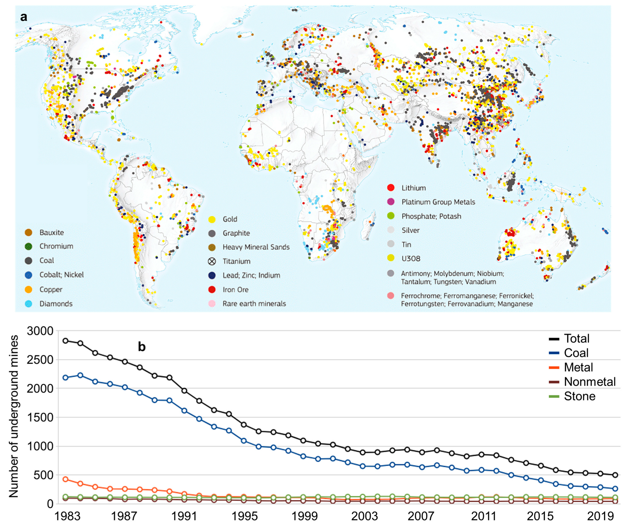
Figure 1. (a) Mining activity around the world [1], (b) Number of underground mines operational in the USA from 1983 to 2019 [3].
Energies 16 00825 g001
Figure 2. Underground gravity energy storage methodological framework.
Energies 16 00825 g002
Figure 3. Underground Gravity Energy Storage system: A schematic of different system sections.
Energies 16 00825 g003
Figure 4. (a) Foldable container to optimize the utilization of the shaft (b) motor/generator sheaves to increase traction on the rotor (side view), and (c) rotor and generator.
Energies 16 00825 g004
Figure 5. (a) upper storage site arrangement of Underground Gravity Energy Storage and UGES (b) fully charged and (c) discharged.
Energies 16 00825 g005
Figure 6. (a) UGES plant in the TauTona mine, 50 km from Johannesburg in South Africa, (b) electricity supply for 1% of South Africa’s demand with the integration of solar power and UGES.
Energies 16 00825 g006
Figure 7. Comparison of long-term energy storage technologies’ installed capacities and energy storage cycles (UGES, PHS, hydrogen, and ammonia) and short-term energy storage (batteries).
Energies 16 00825 g007
Figure 8. Spatial distribution of underground mines and their respective depths.
Energies 16 00825 g008
Figure 9. Spatial distribution of underground mines and their storage potential.
Energies 16 00825 g009
Figure 10. Underground Gravity Energy Storage potential per country in GWh.
Energies 16 00825 g010
Figure 11. Distribution of underground mines per energy storage potential.
Energies 16 00825 g011
Figure 12. Energy storage potential and number of sites per major global region.
Energies 16 00825 g012
Figure 13. Combination of several gravity energy storage technologies. UGES—Underground Gravity Energy Storage. ETGES—Electric Truck Gravity Energy Storage [75]. MGES—Mountain Gravity Energy Storage [74].
Energies 16 00825 g013
Table 1. Comparison of UGES configurations with 10 MW generation capacity.
Sand (tons)Average Height
Difference (m)
Long-Term Energy Storage (GWh)Storage Cycle
(Days)
4,000,0002001.747.27
5004.3618.17
10008.7236.33
40,000,00020017.4472.67
50043.60181.67
100087.20363.33
Table 2. UGES power capacity with different depths, tons of sand, and speeds.
Shaft Depth (m)Container
Dimensions (m × m)
Speed (m/s)Power (MW)
2001 × 10.250.64
0.51.27
12.54
2 × 20.252.54
0.55.09
110.17
4 × 40.2510.17
0.520.34
140.68
5001 × 10.251.59
0.53.18
16.36
2 × 20.256.36
0.512.71
125.43
4 × 40.2525.43
0.550.86
1101.71
10001 × 10.253.18
0.56.36
112.71
2 × 20.2512.71
0.525.43
150.86
4 × 40.2550.86
0.5101.71
1203.42
Table 3. Cost estimate for UGES with 40,000,000 tons of sand, 1000 m, and 30 MW power capacity.
TypeDescription Cost
MaterialDesert sand and water, costing $1 per ton, are the materials chosen for energy storage [58]. The amount of sand required is 40,000,000 tons. The lifetime of the sand is considered to be 100 years.40 million USD
Mining equipmentThe mining equipment consists of dump trucks, conveyor booms, excavators, bucket-wheel excavators, and soil compactors. The lifetime of the mining equipment is ten years.60 million USD
Power generation This item includes the cables, the motor/generators, and the electrical equipment to increase the voltage of the electricity. The power is estimated to have a cost of 2000 USD/kW. The plant has a speed of 0.5 m/s and a power capacity of 30 MW. The lifetime of the power generation system is 20 years.60 million USD
Total costThe UGES energy storage system assumes 40,000,000 tons of sand with an average generation head of 1000 m. 160 million USD
Energy storage costsThe plant’s storage capacity is 98 GWh, and the energy storage investment costs USD $160,000,000.1.6 USD/kWh
Table 4. UGES energy storage costs and power capacities at different depths.
Average Height Difference (m)Energy Storage Costs (USD/kWh)Power Capacity (MW)
2008.26
5003.315
10001.630
15001.145
Table 5. Cost comparison between Seesaw and other technologies [12,22,25,51,70].
Installed
Capacity Cost (USD/kW)
Energy Storage Cost (USD/kWh)Capacity
(MW)
Components Lifetime (Years)
Seasonal pumped hydro storage (SPHS)400–10002–5030–10,000100 (dam),
30 (turbine)
Batteries (Lithium-ion)250150–2000.001–10003–6 (battery)
UGES2000–40001–101–100100 (mine),
10 (trucks),
20 (motor)
Table 6. Amount of carbon sequestered and stored in UGES plant.
Wood (tons)Carbon Dioxide Captured (tones)Average Height
Difference (m)
Energy Storage (GWh)
72,000,000264,000,00020031.392
50078.48
1000156.96
1500235.44
Table 7. Advantages and disadvantages of UGES compared with other gravitational energy storage alternatives.
TechnologiesAdvantageDisadvantage
Energy VaultIt can be implemented in any location. It does not require an existing exhaust mine to operate. The energy storage costs are significantly higher because concrete blocks are more expensive than sand and because the average height of the tower is significantly smaller than in UGES projects.
GravitricityDoes not require upper and lower storage sites. The electricity generation and energy storage are continuous and do not require to be combined with ultra-capacitors or batteries. UGES stores 100 to 10,000 times more energy than Gravitricity, significantly lowering energy storage costs. Gravitricity is limited to one block of mass going up and down.
Lift Energy Storage Technology (LEST)Provides decentralized energy storage services close to the demand for energy storage. There are already building with regenerative braking systems. High-rise buildings are some of the most valuable locations in a city. Filling a building with containers might not be a viable alternative. The building has restrictive ceiling bearing capacity, which restricts the weight a building can support.
Mountain Gravity Energy Storage (MGES) [74]Has potential in locations with high mountains. MGES can also be used to generate hydropower, increasing the overall returns of the project. UGES lower storage site uses a decommissioned mine. MGES upper and lower storage sites can be located a considerable horizontal distance apart, which increases costs and lowers the system’s efficiency.
Electric Truck Gravity Energy Storage (ETGES) [75]Has potential in locations with high mountains. ETGES can also be used to generate hydropower, increasing the overall returns of the project.UGES lower storage site uses a decommissioned mine. ETGES upper and lower storage sites are located at large horizontal distances apart, which increases costs and lowers the system’s efficiency.
Disclaimer/Publisher’s Note: The statements, opinions and data contained in all publications are solely those of the individual author(s) and contributor(s) and not of MDPI and/or the editor(s). MDPI and/or the editor(s) disclaim responsibility for any injury to people or property resulting from any ideas, methods, instructions or products referred to in the content.