Article

Hydrodynamics of Energy-Efficient Axial-Flow Cyclones for Environmentally Safe Cleaning of Gas and Dust Emissions

by
Valery P. Meshalkin
1,2,
Nicolay A. Martsulevich
3,
Oleg M. Flisyuk
3,*,
Ilia G. Likhachev
3 and
Antony M. Nzioka
4
1
Faculty of Digital Technologies and Chemical Engineering, D. Mendeleev University of Chemical Technology of Russia, 9, Miusskaya Square, 125047 Moscow, Russia
2
Frumkin Institute of Physical Chemistry and Electrochemistry, Russian Academy of Sciences, 31, Leninskiy Prospekt, 119071 Moscow, Russia
3
Department of Processes and Apparatus, Saint-Petersburg State Institute of Technology, Technical University, 26, Moskovski Avenue, 190013 St. Petersburg, Russia
4
Silla Entech Co., Ltd., 559, Dalseo-Daero, Dalseo-gu, E&C Innobiz Tower, Daegu 42709, Republic of Korea
*
Author to whom correspondence should be addressed.
Energies 2023, 16(2), 816; https://doi.org/10.3390/en16020816
Submission received: 14 December 2022 / Revised: 30 December 2022 / Accepted: 5 January 2023 / Published: 10 January 2023

Abstract

:
We investigated the operation of an axial-flow cyclone as the most promising dust-cleaning equipment based on energy consumption. Numerical solutions were obtained for the gas-solids suspension flow equations in axial flow cyclones with different separation chambers’ geometry using FlowVision software. The chamber’s geometrical features determined the nature of the gas-solids suspension flow, directly affecting the dusty gases’ purification degree. The circulating gas flows and the turbulent “trace” after the swirl generator were found to negatively influence the cyclone efficiency and the hydraulic resistance values. A high chamber height also negatively affected the gas purification since the bulk of dust particles were removed from the gas-solids flow at the initial section. The initial section’s length coincided with the gas-solids suspension’s jet flow zone due to the flow coming off the swirl vanes’ edges. Due to turbulent mixing, the particles’ secondary entrainment and return to the gas flow began to manifest outside this zone. Based on this analysis, it is possible to develop recommendations for choosing the chamber’s geometric parameters, minimizing the influence of the indicated factors. On the basis of this research, it will be possible to ensure cyclones’ high efficiency with significantly lower hydraulic resistance when designing axial-flow cyclones relative to other types of cyclone.

1. Introduction

The problem of cleaning large-scale gas exhausts from chemical, petrochemical, and thermal power plants running on coal and fuel oil is still relevant. At the same time, significant energy consumption required for dust collection processes is one of the problems due to significant emissions. Therefore, the research and development of dust collector designs is still ongoing to ensure effective particle removal from the gas with low energy consumption. This is proven by several publications focused on the operation of various cleaning equipment, some of which relate to cyclone-type equipment [1,2,3,4,5,6,7]. Thus, the review paper by Misyulya [8] analyzed more than three dozen typical designs of cyclones and separators, indicating their advantages, disadvantages, and preferred application areas. From the perspective of hydraulic resistance and energy consumption, axial-flow cyclone separators have an undeniable advantage: they consume at least half the energy of reverse-flow cyclone separators. However, the widespread use of axial-flow cyclone separators is hindered by the erroneous opinion about the low separation efficiency of their cyclones when cleaning gases from small particles. Meanwhile, several studies have shown that axial-flow cyclones could provide a high degree of purification of dusty gas with particles on the order of 5 microns [9,10,11].
The incorrect assessment of these cyclone separators’ capabilities is due to insufficient knowledge of the flow features of dusty gas in the axial-flow cyclone separator’s separation chamber, which ultimately determine the degree of gas purification. From the perspective of separation efficiency, gas turbulence structure is the most crucial factor in the gas-solids suspension hydrodynamics in the cyclone chamber; this factor is significantly anisotropic in swirling flows. Therefore, the crucial question in the quantitative analysis of the dusty gas flow is how the turbulence model used in the calculation correlates to the actual statistical characteristics of the flow. Currently, several turbulence models have been used for the numerical solution of hydrodynamic equations under turbulent conditions [12,13,14,15,16,17,18,19,20,21,22,23,24,25,26,27]. Chesnokov et al. [28] provide an overview of the models used in the calculations and an assessment of their applicability to describe turbulence in swirling flows. In particular, the standard k–ε model does not adequately describe the gas velocity field compared with experimental data. The accurate model is the SST turbulence model and the nonlinear k–ε model, including quadratic and cubic terms in the Reynolds stress expression.
The objective of this research was to analyze in detail the features of the gas-solids suspension flow in the separation chamber of the axial-flow cyclone separator to identify the factors that limit the use of these types of cyclone separators as effective dust-collecting equipment with low hydraulic resistance.

2. Theoretical Analysis and Methods

2.1. Gas Flow

If the particle mass concentration in the flow is not significant (as is usually the case with cyclones), then their presence has little effect on the gas velocity field. Therefore, the task could be divided as follows: first, we determine the velocity field of the gas phase, and then the nature of particle motion. We introduce a cartesian coordinates system of xi (i = 1, 2,3), directing the axis Ox3 along the axis of the cyclone. Then, according to the Boussinesq hypothesis, which establishes a linear relationship between the Reynolds stress tensor and the strain velocity tensor, the equations describing the gas’s steady motion, taking into account the assumption of its incompressibility, will have the following form:
w 1 x 1 + w 2 x 2 + w 3 x 3 = 0 ρ w 1 w i x 1 + ρ w 2 w i x 2 + ρ w 3 w i x 3 = p ˜ x i + x 1 [ ( μ + μ t ) w i x 1 ] + x 2 [ ( μ + μ t ) w i x 2 ] + + x 3 [ ( μ + μ t ) w i x 3 ] ,           i = 1 ,   2 ,   3
Here μ and μt represent the coefficients of molecular and turbulent viscosity of the flowing medium, respectively (Pa·s). The value p ˜ = p + 2 3 k takes into account the contribution to the static pressure energy of the kinetic energy for turbulent fluctuations: k = ρ i ( w i ) 2 2 .
Equation (1) was solved using the FlowVision software package. The SST turbulence model was used [29,30,31]. After solving the system of equations, it is possible to define not only the pressure profiles and gas velocity projections in the entire flow region, but also the turbulent energy distribution, its dissipation rate, and the attenuation character on solid surfaces. The choice of the computational domain for Equation (1) was determined based on the following considerations. Direct measurement of the gas velocity and flow visualization in the axial-flow cyclone is based on the assumption that each swirl blade forms a flow close to a jet stream. Thus, the gas leaves the peripheral part of the blade edge in the form of a relatively narrow “bundle”. The lower part of the jet stream, which carries the bulk of the dust particles, is relatively quickly washed out, filling the entire cross section of the chamber. This fact is illustrated by the longitudinal projection qualitative distribution results for gas velocity in the chamber’s cross section, presented in Figure 1. Thus, the assumption of the flow’s axisymmetric nature in the cyclone chamber used in several works cannot be fulfilled in real applications [13,17]. The complex picture of the gas velocity distribution at the exit from the swirl blades enabled us to limit the computational domain to the separation chamber of the cyclone only, as was done by Huang et al. [11]. Therefore, we took the cross section of the pipe, located at a distance equivalent to its diameter from the upstream swirler, as one of the computational domain boundaries. At this approximate distance, the flow “feels” the impending obstacle, and the stream profiles begin to be distorted [32]. The gas velocity was assumed to be uniformly distributed and directed along the pipe axis in the indicated section. Another boundary condition was the equality of the gas velocity to zero on all solid surfaces, including the surfaces of the swirl blades (sticking effect).
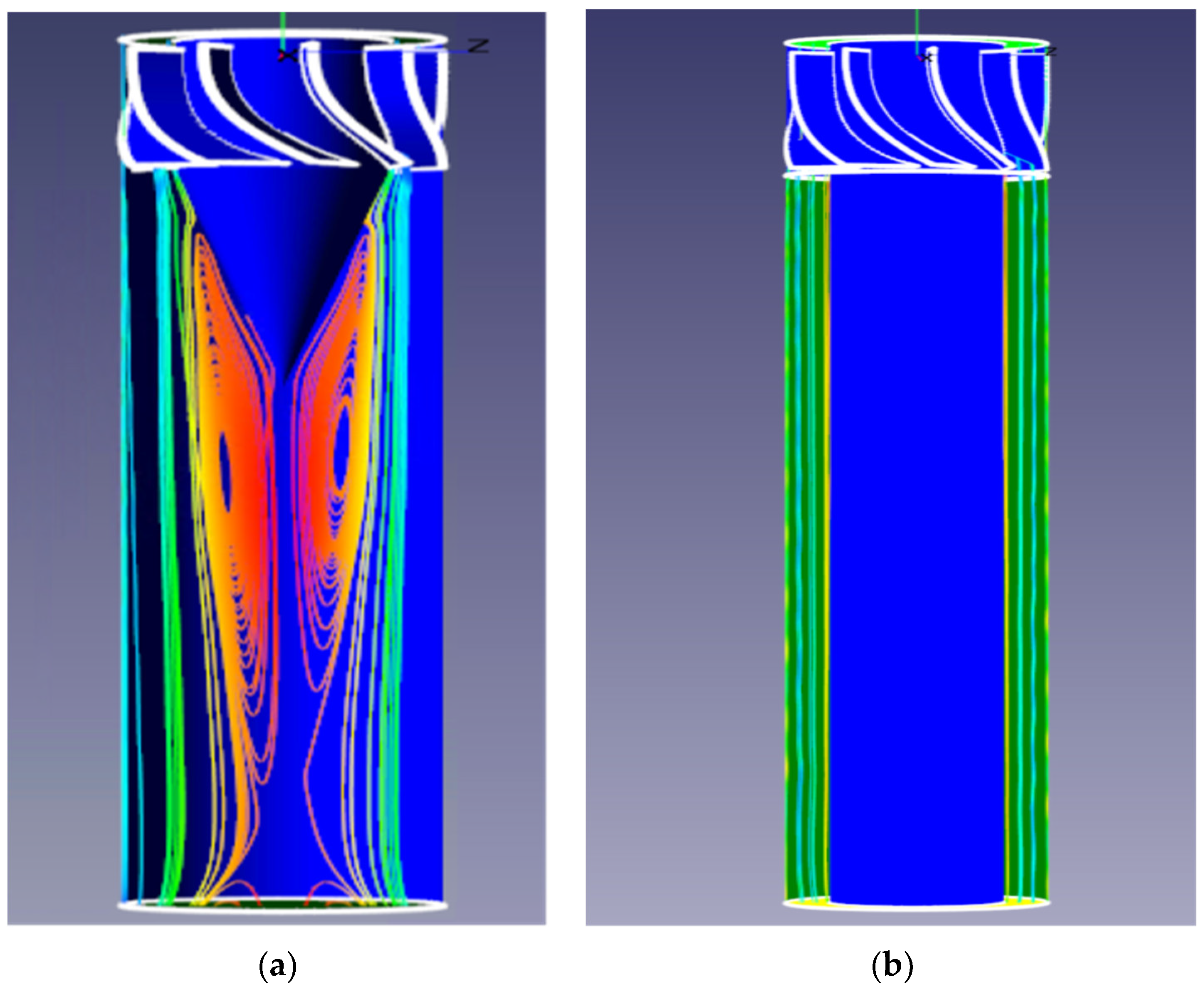
We carried out computation for cyclones with different separation chamber geometries. As it turned out, the stabilizer is the main element of the chamber’s internal geometry: this element, located directly behind the swirler, largely determines the flow pattern, including the value of the hydraulic resistance of the cyclone. The purpose of the stabilizer is to maximize flow damping, eliminate vortex formation caused by flow separation from the blades, and reduce the turbulent “trace” after the swirler. Two types of stabilizers were considered in the computations: conical and cylindrical, with a length equal to the height of the separation chamber (Figure 2). Figure 2 shows the stream profile projections obtained after solving Equation (1) through projection onto a plane passing through the axis of the cyclone. The Reynolds (Re) number calculated for the pipe diameter was 110,000. Figure 2 gives a fairly complete picture of the gas movement characteristics in the separation chamber with this geometry. The flow region is divided into two zones in the first case, where the hydrodynamic pattern is entirely different. In the peripheral zone, the swirling gas flow moves strictly along the chamber wall at high speeds. The central zone is occupied by a turbulent “trace”, in which extensive longitudinal gas circulations are generated.
It is evident that the existence of a “trace” and circulation flows significantly reduce the cyclone’s efficiency and increase its hydraulic resistance. Another such factor preventing the removal of dust particles from the gas flow is their turbulent mixing. In the case of a cylindrical stabilizer, the flow pattern is different. Turbulence is generated only in near-wall regions due to large gradients of the average gas velocity [33,34].
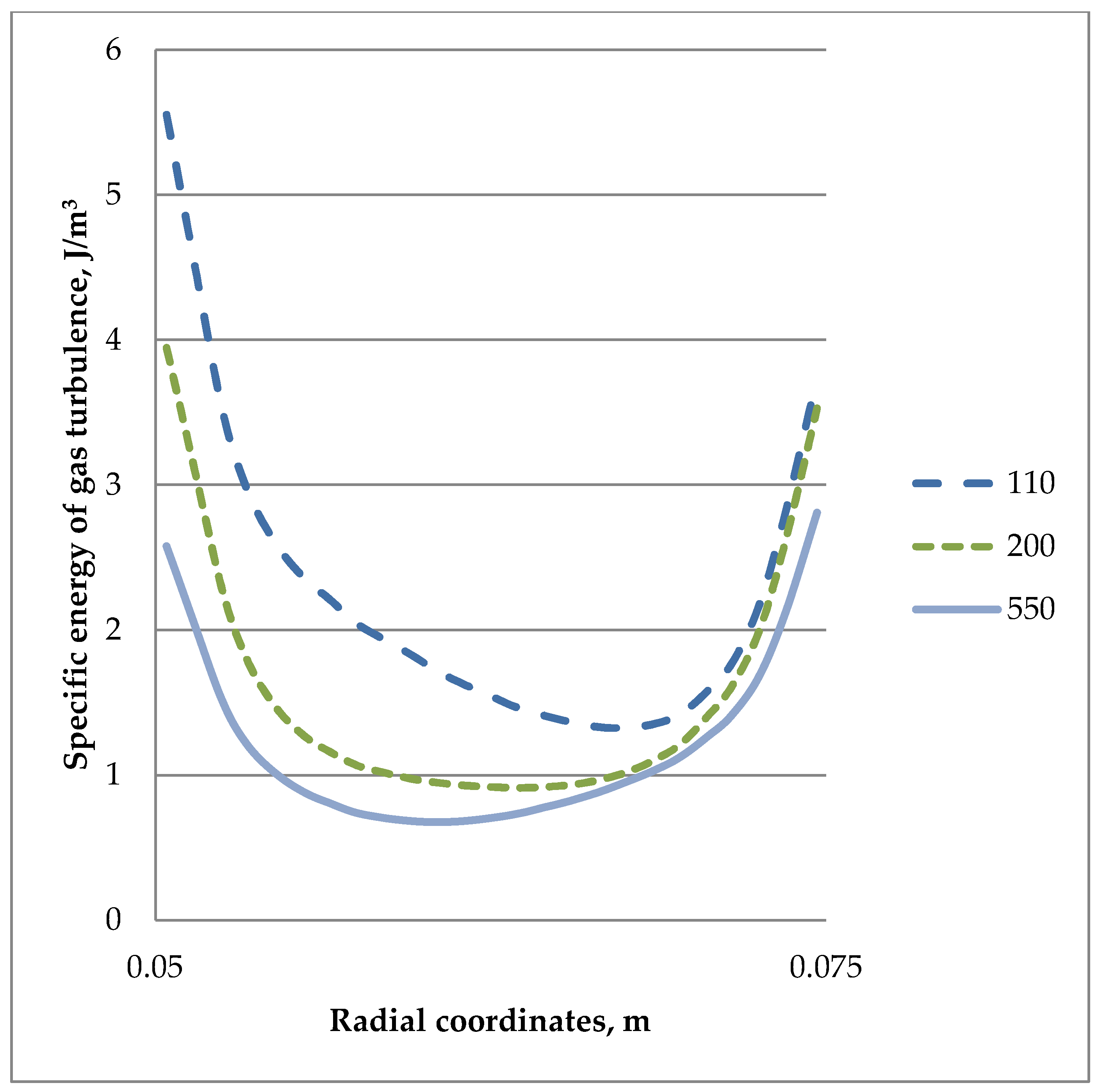
At the same time, the near-wall turbulence zone does not decrease with an increase in the longitudinal coordinates, even if the overall level of turbulence decreases, as evidenced by the graphs shown in Figure 3. This may explain the secondary entrainment of dust particles, already hindered by the wall, into the flow. We could draw certain conclusions regarding the requirements for the separation chambers’ geometry for axial-flow cyclones during their design based on the obtained numerical solutions of the model in Equation (1).
Firstly, the flow stabilizer must be cylindrical. At the same time, the flow stabilizer’s length should not be less than the height of the separation chamber. In this case, the turbulent “trace” would be located outside the chamber (for example, inside the purified gas nozzle). Secondly, the separation chamber should not be extended, in order to ensure that the effect of re-entrainment of particles is minimal.

2.2. Two-Phase Flow

The interpenetrating continuums approach was used to describe the particle-phase flow in the FlowVision package, making it possible to formulate the flow equations for the dispersed phase in a form similar to Equation (1) [35]. The difference is that the gas-phase flow is due to the pressure difference, and the particle-phase flow is due to the force interaction with the gas, as described below:
v 1 mNv i x 1 + v 2 mNv i x 2 + v 3 mNv i x 3 = F i + x 1 [ ( μ t ) v i x 1 ] +   x 2 [ ( μ t ) v i x 2 ] + x 3 [ ( μ t ) v i x 3 ] , i = 1 ,   2 ,   3
The equality of the dynamic coefficients for the turbulent viscosity of the solid and dispersed phases is due to the small size of dust particles when they are almost entirely carried away by turbulent gas stream flows [36,37]. Some particles lagging from the gas was considered in the expression for the interfacial interaction strength, as shown in this expression for the Stokes flow regime:
F = ρ NC D π d 2 8 | w v | ( w v )
where the coefficient of resistance to the particles’ movement from the gas side corresponds to the Stokes flow regime, as shown below:
C D = 24 Re p = 24 μ ρ d | w v | .
The numerical concentration distribution of the dust particles in the cyclone separation chamber adheres to the convective diffusion equation, as described below:
v 1 N x 1 + v 2 N x 2 + v 3 N x 3 = x 1 ( D t N x 1 ) + x 2 ( D t N x 2 ) + x 3 ( D t N x 3 )
The coefficient Dt practically coincides with the kinematic coefficient of the turbulent viscosity of the dispersed phase νt = μt/ρ when the motion of particles is determined only by interaction with gas, since the mechanism of momentum and mass transfer is the same. The computation range for Equation (5) coincided with the computation range for Equation (1); the concentration of particles in the cross section of the pipe located at a distance equivalent to its diameter from the upstream swirler was set as one of the boundary conditions.

3. Results and Discussion

We obtained the dispersed-phase profiles, the dust particles concentration distribution, and the particle flux magnitude in the entire separation chamber volume based on the combined computation of Equations (1)–(5). Computations were carried out for gas-solids suspensions with 5, 15, and 30 microns particles size. The dust particle concentration profiles in the chamber’s cross sections were of particular interest, depending on the distance to the swirler: they are shown in Figure 4.
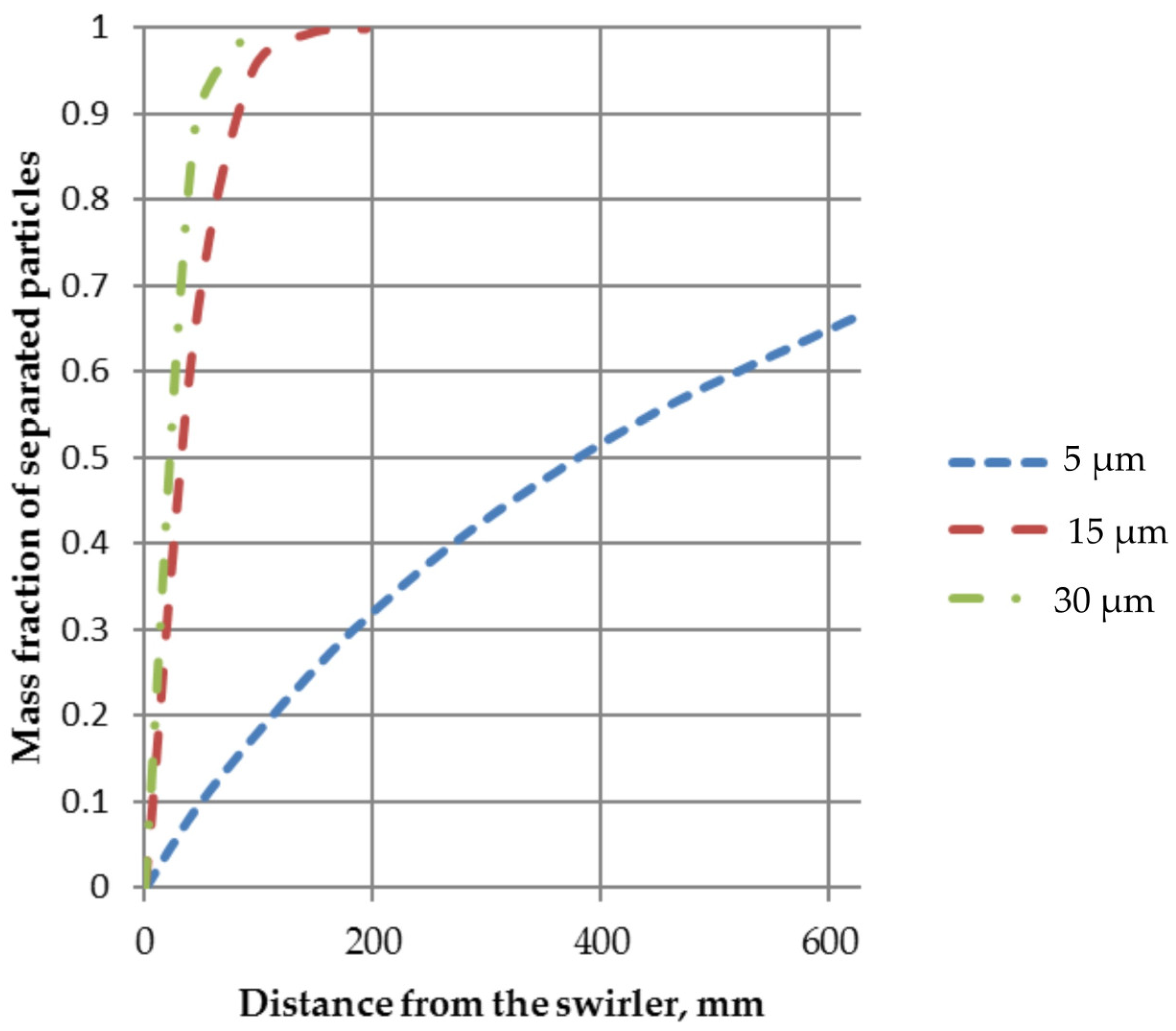
The curves in Figure 4 show that the radial particle mass flow begins before entering the chamber’s swirl blades regions. In other words, significant gas purification from dust particles occurs already in the swirler itself: this is another advantage of once-through cyclones. To a lesser extent, this phenomenon applies to small particles of 5 µm. Attention could be drawn to the fact that the vast majority of the solid phase is removed from the gas flow in the region adjacent to the swirler. When designing a cyclone, it is advisable to enable dust collection at the initial section of the chamber to prevent the particles’ return, already inhibited by the wall, into the gas flow. With this in mind, calculations were carried out based on Equations (1)–(5). The boundary conditions for the particle phase selected for this model consisted of the side surface’s permeability of the chamber for the particle phase. The calculation results are illustrated in Figure 5.
Particles greater than 15 microns are entirely removed from the gas stream at a distance of about 150–200 mm from the swirler. The region’s length is close to the length of the jets’ erosion zone escaping from the blades’ edges. Beyond these limits, the tangential component of turbulent flows smooths out the irregularities of the longitudinal velocity profiles. Smaller particles are removed from the flow to a lesser extent due to turbulent mixing and a weaker effect of centrifugal forces. Therefore, it is advisable to use cyclones consisting of two consecutive separation chambers to clean dusty gases with smaller particles. Apparently, the results presented in this paper are sufficient to demonstrate the fallacy of the estimates of the low efficiency of axial-flow cyclones given in some literary sources. In our opinion, such computed estimates were associated with the inaccurate geometry of separation chambers of the cyclones used by the authors.

4. Conclusions

We identified the physical factors that can serve as reasons for reducing the efficiency of axial-flow cyclones using the numerical solution of the equations of gas-solids suspension hydrodynamics. Firstly, such factors are the possible circulation flows and the generation of additional turbulence due to the separation chamber’s geometry. However, results showed that the influence of these factors is manifested in regions outside of the gas-solids suspension jet flow. At the same time, effective gas dedusting occurs in this area. Results showed that the separation chamber height, stabilizer shape and stabilizer size are the most important geometric parameters determining the axial-flow cyclone’s efficiency. The solutions obtained in this work make it possible at the design stage to carry out a targeted selection of the geometric parameters of the separation chamber, which eliminates or minimizes the negative impact of these factors while maintaining all the advantages of once-through cyclones.

Author Contributions

Conceptualization: O.M.F. and N.A.M.; methodology: V.P.M.; validation: O.M.F. and A.M.N.; formal analysis: N.A.M. and I.G.L.; research: V.P.M.; writing—original draft preparation: O.M.F. and A.M.N.; supervision: V.P.M. and I.G.L. All authors have read and agreed to the published version of the manuscript.

Funding

The research was partially funded by the Russian Science Foundation (project No. 21-79-30029.

Data Availability Statement

Not applicable.

Conflicts of Interest

The authors declare no conflict of interest.

References

  1. Cortés, C.; Gil, A. Modeling the gas and particle flow inside cyclone separators. Prog. Energy Combust. Sci. 2007, 33, 409–452. [Google Scholar] [CrossRef]
  2. Li, Q.; Xu, W.; Wang, J.; Jin, Y. Performance evaluation of a new cyclone separator—Part I experimental results. Sep. Purif. Technol. 2015, 141, 53–58. [Google Scholar] [CrossRef]
  3. Xu, W.; Li, Q.; Wang, J.; Jin, Y. Performance evaluation of a new cyclone separator—Part II simulation results. Sep. Purif. Technol. 2016, 160, 112–116. [Google Scholar] [CrossRef]
  4. Ehteram, M.A.; Tabrizi, H.B.; Mesbah, M.; Ahmadi, G.; Mirsalim, M.A. Experimental study on the effect of connecting ducts on demisting cyclone efficiency. Exp. Therm. Fluid Sci. 2012, 39, 26–36. [Google Scholar] [CrossRef]
  5. Hreiz, R.; Gentric, C.; Midoux, N.; Lainé, R.; Fünfschilling, D. Hydrodynamics and velocity measurements in gas–liquid swirling flows in cylindrical cyclones. Chem. Eng. Res. Des. 2014, 92, 2231–2246. [Google Scholar] [CrossRef]
  6. Elsayed, K.; Lacor, C. The effect of cyclone inlet dimensions on the flow pattern and performance. Appl. Math. Model. 2011, 35, 1952–1968. [Google Scholar] [CrossRef] [Green Version]
  7. Faulkner, W.B.; Shaw, B.W. Efficiency and pressure drop of cyclones across a range of inlet velocities. Appl. Eng. Agric. 2006, 22, 155–161. [Google Scholar] [CrossRef] [Green Version]
  8. Misyulya, D.I.; Kuzmin, V.V.; Markov, V.A. Comparative analysis of the technical characteristics for cyclone dust collectors. Sci. Work. DSTU Chem. Technol. Inorg. Subst. 2012, 3, 154–163. [Google Scholar]
  9. Toptalov, V.S.; Martsulevich, N.A.; Flisyuk, O.M. Purification of smoke and process gases in direct-flow cyclones. Her. SPSTU 2021, 56, 44–50. [Google Scholar] [CrossRef]
  10. Toptalov, V.S.; Martsulevich, N.A.; Flisyuk, O.M. Dusty gas movement in separating chamber of direct-flow cyclone. In Proceedings of the 5th International Conference “Actual Scientific & Technical Issues of Chemical Safety” ASTICS-2020, Kazan, Russia, 6–8 October 2020. [Google Scholar]
  11. Huang, L.; Deng, S.; Chen, Z.; Guan, J.; Chen, M. Numerical analysis of a novel gas-liquid pre-separation cyclone. Sep. Purif. Technol. 2021, 194, 470–479. [Google Scholar] [CrossRef]
  12. Boysan, F.; Ayers, W.; Swithenbank, J. A fundamental mathematical modelling approach to cyclone design. Trans. Inst. Chem. Eng. 1982, 60, 222–230. [Google Scholar]
  13. Hoekstra, A.J.; Derksen, J.J.; Van den Akker, H.E.A. An experimental and numerical study of turbulent swirling flow in gas cyclones. Chem. Eng. Sci. 1999, 54, 2055–2065. [Google Scholar] [CrossRef]
  14. Derksen, J.J.; Van den Akker, H.E.A. Simulation of vortex core precession in a reverse-flow cyclone. AIChE J. 2000, 46, 1317–1331. [Google Scholar] [CrossRef]
  15. Derksen, J.J. Separation performance predictions of a Stairmand high-efficiency cyclone. AIChE J. 2003, 49, 1359–1371. [Google Scholar] [CrossRef]
  16. Elsayed, K.; Lacor, C. The effect of the dust outlet geometry on the performance and hydrodynamics of gas cyclones. Comput. Fluids 2012, 68, 134–147. [Google Scholar] [CrossRef]
  17. Chu, K.; Wang, B.; Xu, D.; Chen, Y.; Yu, A. CFD–DEM simulation of the gas–solid flow in a cyclone separator. Chem. Eng. Sci. 2011, 66, 834–847. [Google Scholar] [CrossRef]
  18. Winfield, D.; Cross, M.; Croft, N.; Paddison, D.; Craig, I. Performance comparison of a single and triple tangential inlet gas separation cyclone: A CFD Study. Powder Technol. 2013, 235, 520–531. [Google Scholar] [CrossRef]
  19. Nassaj, O.R.; Toghraie, D.; Afrand, M. Effects of multi inlet guide channels on the performance of a cyclone separator. Powder Technol. 2019, 356, 353–372. [Google Scholar] [CrossRef]
  20. Gao, Z.; Wang, J.; Liu, Z.; Wei, Y.; Wang, J.; Mao, Y. Effects of different inlet structures on the flow field of cyclone separators. Powder Technol. 2020, 372, 519–531. [Google Scholar] [CrossRef]
  21. Gao, Z.; Wang, J.; Wang, J.; Mao, Y.; Wei, Y. Analysis of the effect of vortex on the flow field of a cylindrical cyclone separator. Sep. Purif. Technol. 2019, 211, 438–447. [Google Scholar] [CrossRef]
  22. Balestrin, E.; Decker, R.; Noriler, D.; Bastos, J.; Meier, H. An alternative for the collection of small particles in cyclones: Experimental analysis and CFD modeling. Sep. Purif. Technol. 2017, 184, 54–65. [Google Scholar] [CrossRef]
  23. Nakhaei, M.; Lu, B.; Tian, Y.; Wang, W.; Dam-Johansen, K.; Wu, H. CFD Modeling of Gas–Solid Cyclone Separators at Ambient and Elevated Temperatures. Processes 2019, 8, 228. [Google Scholar] [CrossRef]
  24. Yao, Y.; Huang, W.; Wu, Y.; Zhang, Y.; Zhang, M.; Yang, H.; Lyu, J. Effects of the inlet duct length on the flow field and performance of a cyclone separator with a contracted inlet duct. Powder Technol. 2021, 393, 12–22. [Google Scholar] [CrossRef]
  25. Gao, Z.-W.; Liu, Z.-X.; Wei, Y.-D.; Li, C.-X.; Wang, S.-H.; Qi, X.-Y.; Huang, W. Numerical analysis on the influence of vortex motion in a reverse Stairmand cyclone separator by using LES model. Pet. Sci. 2022, 19, 848–860. [Google Scholar] [CrossRef]
  26. Celis, G.E.; Loureiro, J.B.; Lage, P.L.; Freire, A.P.S. The effects of swirl vanes and a vortex stabilizer on the dynamic flow field in a cyclonic separator. Chem. Eng. Sci. 2022, 248, 117099. [Google Scholar] [CrossRef]
  27. Zhang, Z.-W.; Li, Q.; Zhang, Y.-H.; Wang, H.-L. Simulation and experimental study of effect of vortex finder structural parameters on cyclone separator performance. Sep. Purif. Technol. 2022, 286, 120394. [Google Scholar] [CrossRef]
  28. Chesnokov, Y.G.; Likhachev, I.G.; Flisyuk, O.M.; Martsulevich, N.A.; Meshalkin, V.P.; Garabadzhiu, A.V. Calculation of flow hydrodynamics in reverse-flow cyclones using the flow vision applied software package. Russ. Chem. J. 2022, 66, 56–60. [Google Scholar] [CrossRef]
  29. Abe, K.; Kondoh, T.; Nagano, Y. A new turbulence model for predicting fluid flow and heat transfer in separating and reattaching flows-II. thermal field calculation. Int. J. Heat Mass Transf. 1995, 38, 1467–1481. [Google Scholar] [CrossRef]
  30. Baglietto, E.; Ninokata, H. Improved Turbulence Modeling for Performance Evaluation of Novel Fuel Designs. Nucl. Technol. 2007, 158, 237–248. [Google Scholar] [CrossRef]
  31. Baglietto, E.; Ninokata, H. Anisotropic eddy viscosity modeling for application to industrial engineering internal flows. Int. J. Transp. Phenom. 2006, 8, 85–101. [Google Scholar]
  32. Van Dyke, M. Album of Fluid Motion; Parabolic Press: New York, NY, USA, 1982. [Google Scholar]
  33. Rotta, I.K. Turbulent Boundary Layer in Incompressible Fluid; Sudostroenie Publishers: Leningrad, Russia, 1967. (In Russian) [Google Scholar]
  34. Shlikhting, G. Theory of Boundary Layer; Nauka Publishers: Moscow, Russia, 1974. (In Russian) [Google Scholar]
  35. Nigmatulin, R.I. Dynamics of Multiphase Substances; Nauka Publishers: Moscow, Russia, 1987. (In Russian) [Google Scholar]
  36. Martsulevich, N.A. Chaotic particle movement in a turbulent gas stream. Theor. Found. Chem. Eng. 1987, 61, 362–367. (In Russian) [Google Scholar]
  37. Martsulevich, N.A.; Protodyakonov, I.O. Chaotic phase flow in gas-solids stream. J. Appl. Chem. 1984, 57, 947–950. (In Russian) [Google Scholar]
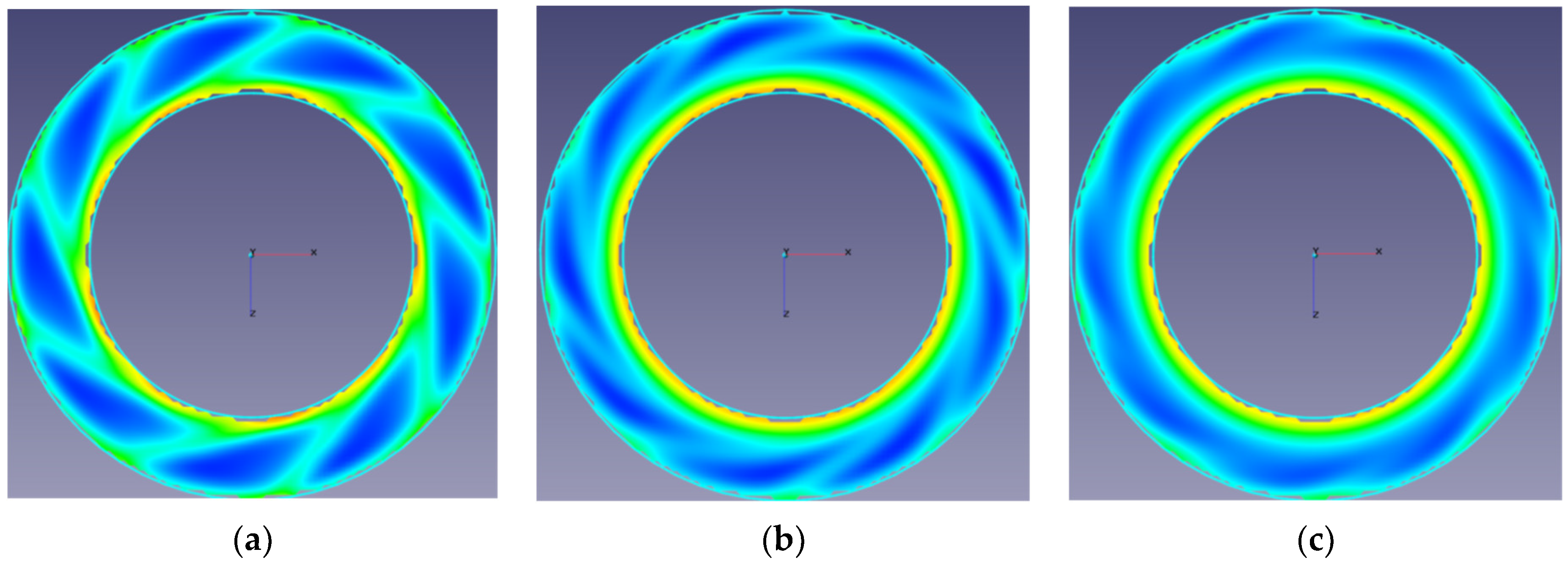
Figure 1. Nature of gas-solids suspension flow jet in the cyclone separation chamber’s inlet area at different distances from the swirler: (a) 10 mm; (b) 50 mm; (c) 100 mm.
Energies 16 00816 g001
Figure 2. Gas flow in separation chambers with different stabilizer geometry: (a) conical; (b) elongated cylindrical.
Energies 16 00816 g002
Figure 3. Specific energy distribution of gas turbulence in the chamber’s cross section: chamber diameter 150 mm; stabilizer diameter 100 mm.
Energies 16 00816 g003
Figure 4. Relative concentration profiles of N/Nin particles in different sections of the separation chamber. Solid line: distance to the swirler was 10 mm; dotted line: distance to the swirler was 100 mm.
Energies 16 00816 g004
Figure 5. The degree of gas purification at different distances from the swirler during lateral sampling of particles.
Energies 16 00816 g005
Disclaimer/Publisher’s Note: The statements, opinions and data contained in all publications are solely those of the individual author(s) and contributor(s) and not of MDPI and/or the editor(s). MDPI and/or the editor(s) disclaim responsibility for any injury to people or property resulting from any ideas, methods, instructions or products referred to in the content.