Abstract
Consuming energy sources and greenhouse gas emission are one of the most prominent problems of the latest century. Most of the energy consumed globally and carbon dioxide emissions originate from electric motors used in the industry. Therefore, researchers have recently focused on the production of highly efficient, eco-friendly, and low-priced machines: Synchronous Reluctance Machines. In this study, the design and comprehensive Finite Element Analysis of a TLA-SynRM including the effects of the number of conductors per slot and wire diameter directly affecting stator slot fill factor and crucial for obtaining more realistic results from experiments has been initially carried out. Moreover, power factor, saliency ratio, and efficiency of the novel SynRM are enhanced by utilizing a fine-tuning process based on d- and q-axes flux paths. Additionally, the layer structure of the initial design is changed to a double-layer structure to improve the performance of the machine in the fine-tuning process. In the final step of this study, the machine has been manufactured, and experiments have been accomplished. This study has concluded that the novel SynRM have low torque ripple, high power factor, saliency ratio, and efficiency, whose value is within the range of IE5 efficiency class.
1. Introduction
Substantial increase in energy consumption and greenhouse gases are leading problems of 21st century since they cause depletion of energy sources and climate change, respectively. Considering that 37% of the energy worldwide and 36% of the greenhouse gases produced originate from the electric motors used in the industry, it is of great importance to produce highly efficient machines leading to decrease in energy consumption and carbon dioxide emissions [1,2]. Among electrical motors, Asynchronous motors also known as Induction Machines, IMs, are highly utilized at industry due to their low cost and straightforward structure [3,4]. However, efficiency of IMs is not satisfactory. In addition to low efficiency, these machines have other drawbacks: difficulties in speed control, high power losses, high weight, and low torque capability [5]. Therefore, designing lighter electrical machines with higher efficiency values and higher torque capability has been gained substantial importance in recent years. Considering disadvantages of IMs, finding alternative electrical machines has become essential. Moreover, in the light of the developments in power electronics circuit design, machines that can be controlled by drivers have begun to come to the fore. As an alternative to IMs, Permanent Magnet Synchronous Machines, PMSMs, have been analyzed and utilized at industry, especially in electrical vehicles in recent years. Although these machines can reach up to quite high efficiency values and can be controlled by the state-of-the-art drivers, magnets used in PMSMs are quite expensive and their production is dependent on Far East countries, especially China [6], leading to restricted access to them.
The insufficient efficiency values of IMs and extremely high cost of PMSMs have prompted researchers to find a different alternative to these machines, Synchronous Reluctance Machines, or SynRMs, since they have lower costs than PMSMs due to not including magnets and higher efficiency values than IMs because of lower power losses [7]. SynRMs also have other attractive features demonstrating the superiority of them to IMs: better stability, higher torque generating capacity, and higher torque per volume than that for IMs [6,8,9]. The main reason of SynRMs’ higher efficiency than IMs is that they do not include conductive materials in their rotor and therefore significantly lower power losses of the rotor and hence lower total power losses of the machine are obtained [10]. Besides, because SynRMs do not have windings in their rotor, the temperature of the rotor of these machines are quite low comparing with IMs and therefore these machines are sometimes called cold-rotor machines. Moreover, the lower temperature of SynRMs causes an increase in their lifetime and maintenance period. Additionally, SynRMs run synchronously and this synchronism causes sensorless control of these machines by means of recent drivers. Furthermore, SynRMs are less costly [11,12] and more accessible than PMSMs since they do not have permanent magnets in their rotor.
On the other hand, higher torque ripple occurred, and low power factor are main disadvantages of SynRMs [13]. The torque ripple of SynRMs can be declined by utilizing different rotor slot pitches for different barriers [14,15,16], using asymmetrical poles [17], skewing [18], defining optimal width of ribs [19], utilizing asymmetrical barriers [20], arranging radial positions of flux barriers [21], using mixed-layer windings [22], etc. To improve power factor of SynRMs, double-layer configuration in windings can be used [23]. Besides, arranging the shape of flux barriers enhances the power factor of these type of machines [24].
In this study, comprehensive analyses on a TLA-type SynRM, including rotor design, conductor per slot, and wire size effects are carried out. These two parameters affect stator slot fill factor and exceeding a certain percentage of this factor causes those windings to not be placed in stator slots. For the values beyond the specified percentage, even if it does not pose a problem analytically, it cannot be realized experimentally. Therefore, considering these parameters during analyzes of SynRMs gives more realistic results. Besides, current and voltage harmonics seen, the variations of machine efficiency and power factor with load are considered experimentally. The details of the machine on which analysis and tests will be performed are shown in Table 1.

Table 1.
Details of the analyzed SynRM.
The further content of this study can be given as follows: the initial design process and its comprehensive analyzes carried out in Section 2. A fine-tuning process to improve the efficiency, η, saliency ratio, ξ, and power factor, cosΦ, of the machine is applied in Section 3. Experiments on the generated novel machine including current and voltage harmonics and the variations of efficiency and power factor with load are achieved in Section 4. Finally, Section 5 contains conclusions obtained from the study and discussions.
2. Initial Design Process and Finite Element Analyzes
The initial design of the analyzed SynRM is based on the design of flux barriers of rotor including effects of barrier number; conductor per slot and accordingly wire size; control angle of rotor slot pitch of top barrier i.e., β; insulation ratios of d- and q-axes and widths of tangential and radial ribs. During analysis, widths of segments and barriers are defined by the ratio of the magnetomotive force, MMF, of consecutive segments and that of the difference between MMF over barriers, respectively [24]. Besides, constant and equal permeance for flux barriers, and uniform flux densities in all segments, are assumed with the utilization of MMF distribution rule in the design of iron and insulation parts of the rotor in this study.
The duration of Finite Element Analyzes, FEAs, carried out varies in the range of 0–1 s based on the duration of reaching steady state of performance parameters. Additionally, the used time step during analyses is 0.8 ms.
2.1. Effects of Flux Barrier Number
During the first analysis, the ratio of the amount of iron to air in q-axis, insulation ratio, kq = 0.5 is taken. However, the distributions of iron and air are not considered during the first analysis since the only consideration of the analysis is to see how the machine performance parameters are influenced by the variation of the number of flux barriers and to obtain the optimum flux number for the further analyses of the novel SynRM.
The comparison of the effect of number of flux barriers on machine performance parameters are carried out and the results are shown in Table 2. While comparing them, rotor position is stabilized at 52 deg to obtain realistic results.

Table 2.
Flux barrier number analyzes.
Table 2 states that the highest output torque, Te, is obtained for two-barrier structure at the same position. However, this design cannot be considered as the optimal design since torque ripple, Trip, of this design is much more than that of four and five barrier designs. Additionally, ξ, cosΦ, and η values of the design are worse than the last three designs. Among these designs, although the last design has the lowest Trip, and lower total power loss, Ptotal, than the SynRM with four barriers, the latter can be considered as optimum design since it has the highest ξ, cosΦ, and η values. To reduce Trip of this design further optimization is utilized and explained detailly in further steps of this study.
2.2. Effects of Conductor per Slot and Wire Size
The analysis on conductor per slot is crucial for the analysis of SynRMs since it affects the stator slot-fill factor that must be considered during the design of SynRMs, especially for experiments. The conductor per slot is also effective on the wire diameter used in windings. During this analysis, Te is kept around 140 N·m. The variation of machine performance parameters with the change of conductor per slot and accordingly wire size is depicted in Table 3.

Table 3.
Conductor per slot and wire size analyzes.
The fill factor is kept being just below 60% indicated in the table for each conductor/slot value to place windings inside the slots for manufacturing process. To keep this factor around given ratio, wire diameter is gradually decreased as conductor/slot increases. Additionally, rms value of the current drawn by the machine declines with the increment of conductor per slot. Moreover, Ptotal of the machine nonlinear changes seen in the table. The optimum values of conductor per slot and wire size are chosen as 28 and 0.945 mm, respectively, since the highest η and cosΦ are obtained at these values. Furthermore, Ptotal of the machine has its lowest value at that condition.
2.3. Effect of β Controlling Angle
Rotor slot pitch angles, αsp values, can be obtained by positions of the barrier end points in d-axis shown in Figure 1. These angles can be selected at fixed or variable intervals during the design of SynRMs. In this study, β is defined as a controlling parameter of the rotor slot pitch angle of the top barrier and this parameter is highly effective on Trip of the machine. By introducing this parameter, the barrier end points can be arranged to obtain better results, especially for less Trip. Besides, β has less influence on Te than Trip.
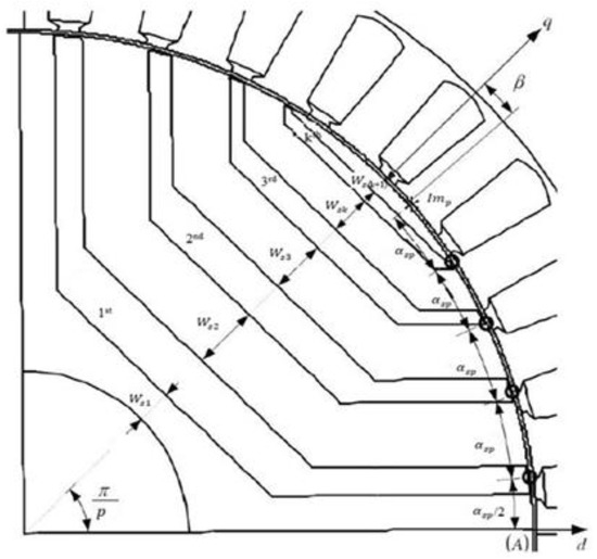
Figure 1.
Rotor slot pitch angle, αSP, and its control parameter, β.
The figure illustrates that β is also the angle between q-axis and the imaginary point, Imp. Effects of this parameter on the performance of the analyzed SynRM are given in Table 4. During the analysis β is varied from 7 to 14.

Table 4.
Analyzes on control angle.
The table states that cosΦ, ξ, and η tend to decrease as the angle increases in general. Te and Irms usually decrease with the increment of β seen from the table. However, Te does not substantially change for the values greater than β = 9. Since the aim of this analysis is to obtain the lowest Trip, β = 11 is chosen as the optimum value.
2.4. Effects of Insulation Ratios
Effects of dq-axes insulation ratios, kd, and kq, on the performance of analyzed SynRM are investigated after the lowest Trip is obtained for β = 11 in the previous analysis. Insulation ratios mostly affect Te of SynRMs, and they are generally used for torque maximization during the design of SynRMs. These ratios can be basically defined as the ratio of total amount of air to that of iron on the relevant axis.
The effect of kq on machine performance is initially analyzed between 0.65 and 0.75 and the results are indicated in Table 5.

Table 5.
Analyzes on q-axis insulation ratio.
The table shows that Te of the machine improves by 14.53% with the increase of kq from 0.65 to 0.75 since the increment in this ratio causes the rise in the amount of air in this axis leading to decrease in q-axis inductance, Lq. However, the variation of kq does not really affect the Trip, differing only 2.11% in the given range. Besides, Irms increases with the augmentation of this ratio. Moreover, cosΦ and η of nonlinearly changes, but generally they tend to increase with augmentation of kq. However, ξ of the machine gradually rises with the enhancement of kq due to diminution in Lq. Considering these effects, kq = 0.7 is chosen as the optimum insulation ratio in q-axis since it has lower Trip, higher ξ, cosΦ, and η values.
The d-axis insulation ratio, kd, is another parameter affecting performance of SynRMs, especially Te. This ratio is varied in between 0.3 and 0.4 with 0.02 steps during the analyses of its effect on the machine performance and results are indicated in Table 6.

Table 6.
Analyzes on d-axis insulation ratio.
The table indicates that Te, Trip, and Irms change nonlinearly with the variation of kd; however, the increase of this ratio from 0.3 to 0.4 causes an 8.46% reduction in Te. Among kd values, 0.34, 0.35, 0.36, and 0.38 give the closer Te for the analyzed SynRM. Considering these values, cosΦ and η for kd = 0.34 are higher comparing with the others. Additionally, Te of the machine has the closest value to its nominal value. Moreover, Trip at that insulation ratio is comparable with its lowest value and ξ at that ratio is quite satisfactory. Therefore, kd = 0.34 is decided as the optimum d-axis insulation ratio in this study.
2.5. Effects of Ribs
Utilization of SynRMs at high speeds can be challenging since the flux barriers may be frangible and deformable at these speeds. To obtain more durable SynRMs, ribs connecting the segments are required during the design of rotor of these machines [25,26,27], because the ribs prevent the flux barriers from breaking or deforming because of centrifugal forces that occur directly depending on the speeds. The saturation of the ribs is carried out by q-axis flux, Ψq. The width of the ribs should be considered in the rotor design since it has a big influence on Te, because widening the ribs causes to increment in Ψq, and hence increase in Lq leading to decrease in Te. Additionally, introducing the ribs also causes the rise in Trip of the machine. Moreover, the increment in rib widths causes a reduction in ξ due to increment in Lq and leads to decrease in cosΦ of the machine. Performance parameters varying with the change of radial rib widths, W, are given in Table 7.

Table 7.
Analyzes on radial rib widths.
The table states that Te decreases generally as the radial ribs are wider. Because enhancement in W causes an increase in Lq due to increase in iron part along q-axis, the 13.54% reduction of Te occurs with the increase of W from 1 mm to 2 mm. Moreover, widening the radial ribs brings about a decrease in ξ due to increase in Lq. Besides, the rms value of the current declines with the improvement in radial rib width. Furthermore, copper and iron losses, Pcop and Pfe, alter with the change of radial rib widths. Pcop decreases with the increment of W due to reduction in Irms whereas Pfe is slightly affected by the change of W. Ptotal also decreases as radial ribs are widened. Considering all the results, the design with 1 mm width is considered as the optimum design width since the highest cosΦ and η are obtained at that value among the values supplying the required Te.
Tangential ribs near the airgap connect the segments of rotor such as radial ribs. Manufacturing benefits are obtained when tangential ribs are used. Utilization of tangential ribs gives increases in circulating component of Ψq. In addition to that, these ribs cause a decrease in Ld, indirectly originating from the q-axis cross-coupling on d-axis. Due to of Ld reduction and Lq improvement, Te of created SynRM declines with the increase in widths of tangential ribs. Ht, given in Table 8.

Table 8.
Analysis on tangential rib widths.
The table depicts that 11.96%, 7.61%, and 0.4% reductions in ξ, cosΦ, and η, respectively, are obtained with 0.8 mm increase of Ht. However, Trip is not significantly affected by the change of Ht. Besides, Pcop of the machine decreases significantly while the reduction of Pfe is slight. Therefore, Ptotal decreases as tangential ribs are wider due to decrease in Pcop and Pfe. Among the given range, Ht = 0.8 mm cannot be considered as the best option. This is not only caused from excessive Te but also manufacturing difficulties occurred at that value. The values below 1 mm are not recommended in terms of production since the laser cutting of the sheets is challenging and it may be broken at high speeds. Hence, the optimum value of the tangential ribs is chosen as Ht = 1 mm. Because it gives required Te and has the highest ξ, cosΦ, and η among the remaining values.
The final overview of the Initial design is shown in Figure 2.
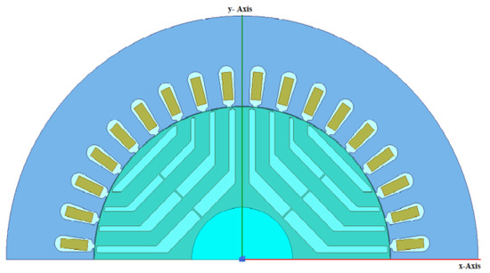
Figure 2.
The overview of the initial design.
3. Fine-Tuning
The results of initial design are quite satisfactory in terms of Te, Trip, and η. However, cosΦ of this machine is lower than that of the former. Therefore, a further optimization technique called fine-tuning, considering the path of d- and q-axes flux lines of solid rotor, especially d-axis, is utilized mainly to improve the cosΦ of the novel design. Besides, a minor improvement in efficiency is aimed with the fine-tuning.
Obtaining the maximum anisotropy is the main concern during the design of SynRMs. The keynote of achieving the anisotropic structure is to ensure a smooth path for Ψd and to obstruct Ψq as much as possible since these conditions lead to acquiring higher Ld and lower Lq as desired in the design of SynRMs. Because, obtaining these inductances gives result in higher values of ξ, cosΦ, and Te. Moreover, to have a minimum reluctance in d-axis and maximum reluctance in q-axis, Ψd must have a clear path. whereas Ψq must be blocked at the maximum level simultaneously [28].
Flux lines of a solid rotor of a SynRM are shown in Figure 3 [29].
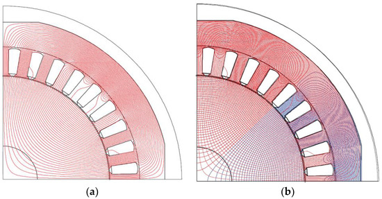
Figure 3.
Flux lines of a solid rotor of a SynRM: (a) d−axis; (b) d− and q−axes.
The lines of d-axis are perpendicular to these of q-axis demonstrated in the right side of the figure. Therefore, creating barrier shapes in parallel with the behavior of d-axis flux, Ψd, can be considered as the optimum way during the design of SynRMs since generating that type of barriers also blocks Ψq simultaneously due to orthogonality.
Barriers with the shape of d-axis fluxes can be generated by the utilization of the equation of N. E. Joukowski called this airfoil potential function [30] utilized during the fine-tuning process.
The fine-tuned version of the novel SynRM and magnetic field density, B, is shown in Figure 4. The analyses have been carried out considering the half part of the machine.

Figure 4.
Fine−tuned SynRM: (a) Overview; (b) Magnetic flux density.
Figure 4b illustrates that B is high at radial and tangential ribs, whereas it is low at the other parts of rotor and stator. It should also be declared that the change of this intensity depends on the rotor position.
The double-layer winding scheme is utilized to improve the performance of the novel SynRM. However, the delta connection is still used in the windings. The FEAs of fine-tuned SynRM have been accomplished along 1 s with 0.8 ms steps. Besides, Dirichlet boundary conditions in which zero vector potentials are assigned to boundaries of machine parts—stator, rotor and shaft—have been used during the fine-tuning. Moreover, the operation temperature and rotor position of the machine are set to 75 °C and 53.95 deg., respectively. Variations of Te and power losses, i.e., Pcop and Pfe, on the fine-tuning process are demonstrated in Figure 5.
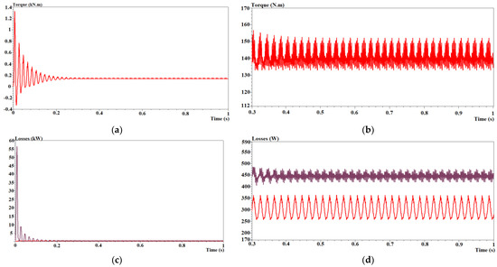
Figure 5.
The results of FEAs of the fine−tuning: (a) Te; (b) Zoomed Te; (c) Pcop and Pfe; (d) Zoomed Pcop (shown with purple) and Pfe (shown with red).
Figure 5 illustrates that values of both Te and Pcop reach to approximately 9 times their steady-state values since stator current of machine is very high during the startup and both the output torque and copper loss depend on this current. The average values of Te and Trip obtained both from the 0.8 s and 1 s time interval of the fine-tuned SynRM are 140.8 N·m and 13.72%, respectively, and demonstrated in Figure 5a,b. Additionally, changes of Pcop and Pfe of the fine-tuned machine in the given range are shown in Figure 5c,d. The average values of Pfe and Pcop are 300.6 W and 445.4 W, respectively. Besides, Ptotal is obtained as 1131 W by addition of Pother, 385 W obtained from analysis results of existed IM. Moreover, ξ and cosΦ of the fine-tuned SynRM are obtained as 9.0599 and 0.774, respectively.
The results of the comparison of the initially designed and the fine-tuned SynRMs are given in Table 9.

Table 9.
Comparison of Finite Elementally analyzed SynRMs.
The table depicts that Te values of both designs are kept around 140 N·m to carry out a better comparison. Trip of the optimized design is 1.46% lower than that for the fine-tuned SynRM given in the table. The rounding flux barriers causes an increase in the amount of air in q-axis leading to reduction in Lq. The decrease in Lq brings about the improvement in the ξ and cosΦ of the fine-tuned machine. Moreover, ξ and cosΦ of the fine-tuned SynRM are 9.68% and 2.38% higher than these for the initial design, respectively. Furthermore, 65.9 W reduction of Ptotal and 0.29% enhancement in η are achieved with fine-tuning process.
4. Experiment
4.1. Basics of the Experiment
The implementation of the novel SynRM is carried out, having completed the FE analyzes of fine-tuning of the machine. During the experiments, silicious sheets with the type M470-50A are utilized while forming rotor and stator. Magnetic flux density and magnetic field strength values of these sheets are obtained from the existed dataset of this material. One of processed rotor sheets of the used sheet is illustrated in Figure 6.
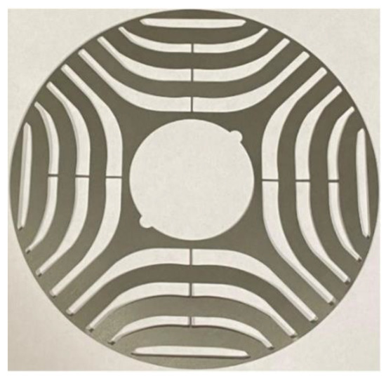
Figure 6.
The view of a processed rotor sheet.
The manufactured novel SynRM, the driver, and test system utilized are shown in Figure 7.

Figure 7.
Experimental setup: (a) Manufactured SynRM; (b) Driver; (c) Test system.
A fan made from plastic is attached to the novel SynRM for cooling the machine illustrated in Figure 7a. To load the machine, an IM capable of producing torque up to 1500 N·m is used in the test system shown in Figure 7b. Besides, a torque sensor is utilized between the SynRM and the IM to calculate the output torque of the machine. In the test system, the mains voltage is supplied to the input of the driver and transmitted to the machine from the output of the driver. The machine is driven with ABB-ACS880-01 driver shown in Figure 7c.
4.2. Tests and Results
Tests were carried out in a laboratory in accordance with IEC 60034-1 standards [31]. The machine is loaded to its nominal value of 140 N·m from the beginning of the test. The test of the novel machine lasts 12,000 s corresponding to 3.34 h. Besides, to see the performance of the manufactured SynRM in different loads, the machine is loaded with different load values than its nominal load value. Moreover, the machine is performed at 1500 r/min during tests. The novel SynRM is controlled by Direct Torque Control, DTC, by ABB-ACS880-01 driver. To show how efficient the created SynRM is, efficiency values of the machine and of the driver have been considered during the test. The temperature from the body of the machine by means of a temperature sensor has also been measured to reveal how the temperature of the machine is low. Test results are demonstrated in between 11,750 s and 12,000 s and shown in Figure 8.
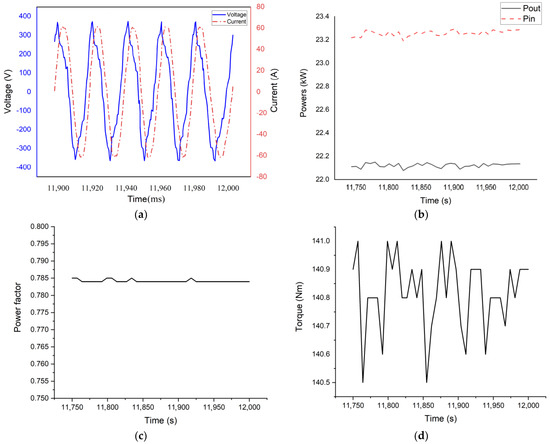
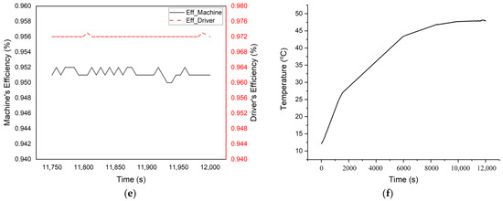
Figure 8.
Test results: (a) Current and Voltage of Phase A; (b) Input and output powers; (c) Power factor of the machine; (d) Output torque; (e) Efficiencies; (f) Temperature of the machine.
The change of the current drawn by the machine and the voltage of Phase A in the range of 11,900–12,000 ms is shown in Figure 8a. The figure illustrates that the maximum value of the current of the given phase is around 61 A, whereas the rms value of this phase is obtained as 42.7 A. On the other hand, the maximum value of the voltage of the given phase is 400 V. Moreover, current and the voltage of Phase A are slightly distorted and seen in the figure.
The display of input and output powers, Pin and Pout, of the machine is given in Figure 1b. The figure illustrates that Pin of the machine alters in between 23.2 kW and 23.3 kW whereas Pout of the machine varies in the range of 22.1 kW and 22.2 kW. Since the manufactured SynRM reaches to its rated value of phase voltages together with its nominal torque value at 11,757.8 s, nameplate values of Pin and Pout of the machine are obtained as 22.077 kW and 23.191 kW, respectively, at that time.
Variations of cosΦ of the machine are shown in Figure 8c. The figure depicts that cosΦ of the machine is almost constant around 0.785 in the given range. Finally, the nominal cosΦ of the novel SynRM is obtained as 0.784 with rated phase voltages at 11,757.8 s.
The demonstration of Te is indicated in Figure 8d. The torque is set to its nominal value, 140 N·m, in the given range of the test. Since the output torque has a set value, the Trip is measured as 1.5% in this range. The obtained torque at the rated Pout with the highest efficiency is taken as 140.5 N·m at 11,757.8 s.
The efficiency values of the manufactured machine, and the driver are demonstrated in Figure 8e. The η of the machine alters in between 95% and 95.2% seen in the figure. Moreover, η of the machine is obtained as 95.2% at 11,757.8 s. It should be depicted that this η value is within the range of IE5 efficiency class considering the experimental tolerance defined by IEC.
The variation of the temperature measured from the body of the machine is demonstrated in Figure 8f. The figure depicts that the temperature significantly increases from almost 12 °C to 47.5 °C from the beginning of the test up to 9000 s. Beyond that time, it slightly increases, and the final temperature of the machine reached is measured as 48.1 °C. It should be emphasized that “Mylar” insulation material with H-class isolation is utilized in stator slots and between phases.
The 3rd, 5th, and 7th harmonics of line voltages and phase currents are the most effective harmonics seen in the machine, and the average values of them are shown as histograms with blue and red bars, respectively, in Figure 9. In addition to these harmonics, the average values of total harmonic distortions, THD, of line voltages and phase currents obtained are demonstrated on the left side of the figure.
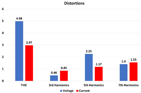
Figure 9.
3rd, 5th, and 7th harmonics and THD values of phase voltages and currents.
The figure demonstrates that 5th harmonic is the most effective harmonic among line voltages with 2.25% whereas the 7th harmonic has the highest value among current harmonics with 1.55%. Moreover, THD of line voltages is 4.98%. On the other hand, average THD value of phase currents is 2.97%. Furthermore, THD values of voltage and current are both below 5%, complying with international standards for electrical machines.
Since electrical machines might not be operated continuously at the same and full load in the environment in which they are used, it is desirable that their efficiency at different load values be as high as possible. Therefore, the manufactured SynRM has been tested in different loads to see how efficient the novel SynRM at these loads and the results are illustrated in Figure 10.
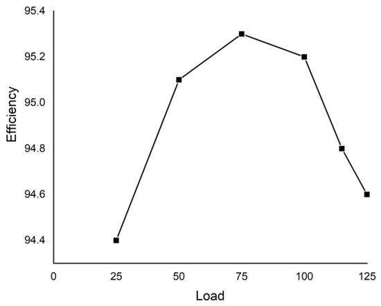
Figure 10.
Variation of the efficiency with different loads.
The figure demonstrates that the efficiency of the generated SynRM at full load is 95.2%, the machine reaches its most efficient value, i.e., 95.3%, at 75% load value. The machine’s efficiency at 25% and 125% load are 94.4% and 94.6%, respectively.
The results of the test of the manufactured SynRM can be summarized in Table 10. It is emphasized again that the test of the machine lasts 12,000 s and the values at the table are obtained at 11,757.8 s.

Table 10.
Experimental Results.
The efficiency of the manufactured SynRM is 95.2% within the range of IE5 efficiency class considering the tolerance of experiments according to established IEC standards. In addition to that, obtained power factor of the machine is quite satisfactory, i.e., 0.784. Moreover, harmonics of line voltages and phase currents are quite low, below 5%. It should be declared that no vibration or noise occurred in the machine during the test. Besides, obtained torque ripple is 1.5% since the machine’s Te is set around 140 N·m. Furthermore, the highest temperature from the body of the machine reached is 48.1 °C and current drawn by the machine is 42.7 A.
4.3. Comparison of FEAs and Experimental Results
The results of FEAs of an existing IM, initially designed SynRM, fine-tuned SynRM, and experiments are summarized in Table 11.

Table 11.
Comparison of SynRMs.
The operating frequency of the machines during analyses and tests is 50 Hz. The table depicts that Te of SynRMs is almost kept constant around its nominal value, i.e., 140 N·m. Trip values of initially design, fine-tuned, and the manufactured SynRMs are 6.17%, 3.71%, and 15.93% lower than that for the IM, respectively. It should be clarified that the very low value of Trip of the manufactured SynRM is caused by the utilization of the driver and is due to the machine being loaded to its nominal value from the beginning of the experiment. Additionally, comparing with the initial SynRM, ξ is improved from 8.26 to 9.0599 with the utilization of the fine-tuning process seen in the table. All SynRMs given in the table have lower Ptotal than that for the existing IM. Among the analyzed SynRMs, Ptotal of the manufactured SynRM has 17 W and 82.9 W lower than that for the fine-tuned and parametric optimized SynRMs, respectively. The reason of obtaining lower Ptotal in the tests is that Pother have been taken as from tests of the existing IM as 385 W during the FEAs of SynRMs and these losses are expected to be lower for SynRMs than IMs.
According to the table, the IM has the highest power factor. Additionally, cosΦ of the fine-tuned SynRM is higher than that for the firstly designed SynRM since the main aim of the fine-tuning is to improve cosΦ of the machine and it has been achieved with the applied process. Moreover, cosΦ of the manufactured SynRM is better than that for the fine-tuned SynRM and it may be caused from a minor possible calculation error of cosΦ values calculated from the graph by lagging between the chosen phase current and phase voltage of SynRMs during FEAs. The final and the most important results need to be considered are efficiency values of the machines considering increase in electrical consumption and greenhouse gases. Furthermore, the table depicts that η of fine-tuned SynRM is 3.01% and 0.29% higher than that for the IM and the initial SynRM, respectively. The obtained η for the manufactured SynRM is 95.2% corresponding to IE5 efficiency class standards considering the experimental tolerances defined by IEC. The reason of acquiring higher efficiency than FEAs of the fine-tuned machine is the same with the abovementioned reason of Ptotal.
As a result, the manufactured SynRM at the rated power has quite impressive results of performance parameters, i.e., 95.2% η within the IE5 efficiency class, 0.784 cosΦ, and 1.5% Trip.
5. Conclusions
In this study, comprehensive analyses of SynRMs are carried out with FEAs and experiments. During FE, analyses utilized a 22 kW TLA-SynRM, an initial design including effects of barrier number; conductor per slot and accordingly wire size analyses; control angle of rotor slot pitch of top barrier, i.e., β; insulation ratios of dq-axes and widths of tangential and radial ribs are accomplished. Among these analyses conductor per slot and wire size analyzes have not been previously considered in the literature. However, they are both effective on machine performance since they directly affect the stator slot-fill factor, and if this ratio exceeds a certain value, which can change for the used program, it is not possible to place the windings in slots. With the utilization of fine-tuning, although Trip increases by 2.46%, the values of cosΦ, ξ, and η of the machine are improved by 2.38%, 9.68%, and 0.29%, respectively. Having obtained satisfactory results from FEAs, the manufacturing process and experiments are achieved. The results of the experiments coincided with the fine-tuned SynRM. The power factor and efficiency of the manufactured SynRM are respectively obtained as 0.784 and 95.2% which is in the range of IE5 efficiency class considering experimental tolerance. Since the machine is loaded around to its nominal value, i.e., 140 N·m, Trip of tests is obtained as 1.5%.
Comparing with the previous studies on SynRMs, the novel SynRM is more efficient than the SynRM created in [32,33]. Efficiency of [32,33] are around 90% and 85%, respectively, whereas that for the novel design is 95.2% placed in IE5 efficiency class considering the experimental tolerances defined by IEC. Moreover, the proposed design has 1.64% and 13.623% higher values of efficiency and power factor comparing with [34]. To sum up, the proposed SynRM has quite fascinating results with its high efficiency, power factor, and low torque ripple values.
Author Contributions
Methodology, A.O. and Y.U.; Software, A.O.; Validation, Y.U.; Investigation, A.O.; Resources, Y.U.; Data curation, A.O.; Writing – original draft, A.O.; Supervision, Y.U. All authors have read and agreed to the published version of the manuscript.
Funding
This research received no external funding.
Data Availability Statement
Data available on request due to restrictions eg privacy or ethical.
Conflicts of Interest
The authors declare no conflict of interest.
References
- Almeida, A.T.; Ferreira, F.J.T.E.; Baoming, G. Beyond Induction Motors—Technology Trends to Move up Efficiency. IEEE Trans. Ind. Appl. 2013, 50, 2103–2114. [Google Scholar] [CrossRef]
- Kabir, M.A.; Husain, I. Design of synchronous reluctance motor with multilayer AC winding. In Proceedings of the 2017 IEEE International Electric Machines and Drives Conference (IEMDC), Miami, FL, USA, 21–24 May 2017. [Google Scholar]
- Ozdil, A.; Uzun, Y. Design and Analysis of a Rotor for a 22 kW Transversally Laminated Anisotropic Synchronous Reluctance Motor. Elektron. Ir Elektrotechnika 2021, 27, 17–24. [Google Scholar] [CrossRef]
- Lee, J.; Jung, D.; Lim, J.; Lee, K.; Lee, J. A Study on the Synchronous Reluctance Motor Design for High Torque by Using RSM. IEEE Trans. Magn. 2017, 54, 1. [Google Scholar] [CrossRef]
- Boglietti, A.; Pastorellli, M. Induction and synchronous reluctance motors comparison. In Proceedings of the 2008 34th Annual Conference of IEEE Industrial Electronics, Orlando, FL, USA, 10–13 November 2008. [Google Scholar]
- Panda, S.; Keshri, R.K.; Vidyadharan, A. Design and Fabrication of Synchronous Reluctance Motor for Light Electric Vehicle Applications. In Proceedings of the 2019 IEEE Transportation Electrification Conference (ITEC-India), Bengaluru, India, 19–21 June 2019. [Google Scholar]
- Sankestani, M.M.R.; Siadatan, A. Design of outer rotor synchronous reluctance motor for scooter application. In Proceedings of the 2019 10th International Power Electronics, Drive Systems and Technologies Conference (PEDSTC), Shiraz, Iran, 12–14 February 2019. [Google Scholar]
- Lin, I.; Hsieh, M.; Kuo, H.; Tsai, M. Improved Accuracy for Performance Evaluation of Synchronous Reluctance Motor. IEEE Trans. Magn. 2015, 51, 8113404. [Google Scholar] [CrossRef]
- Lavrinovicha, L.; Dirba, J. Comparison of permanent magnet synchronous motor and synchronous reluctance motor based on their torque per unit volume. In Proceedings of the 2014 Electric Power Quality and Supply Reliability Conference (PQ), Rakvere, Estonia, 11–13 June 2014. [Google Scholar]
- Zakharov, A.V.; Malafeev, S.I.; Dudulin, A.L. Synchronous reluctance motor: Design and experimental research. In Proceedings of the 2018 X International Conference on Electrical Power Drive Systems (ICEPDS), Novocherkassk, Russia, 3–6 October 2018. [Google Scholar]
- Diao, X.; Zhu, H.; Qin, Y.; Hua, Y. Torque Ripple Minimization for Bearingless Synchronous Reluctance Motor. IEEE Trans. Appl. Supercond. 2018, 28, 5205505. [Google Scholar] [CrossRef]
- Hrabovcova, V.; Rafajdus, P.; Lehocky, P.; Makys, P.; Kremen, M. Design of Low Voltage Reluctance Synchronous Motor. In Proceedings of the 2018 International Symposium on Electrical Machines (SME), Andrychow, Poland, 10–13 June 2018. [Google Scholar]
- Nattuthurai, S.; Neelamegham, R. Design and performance evaluation of SynRM and ferrite assisted-SynRM for EV application using FEA. In Proceedings of the 2017 International Conference on Smart Technologies for Smart Nation (SmartTechCon), Bengaluru, India, 17–19 August 2017. [Google Scholar]
- Ma, X.; Li, G.; Zhu, Z.; Jewell, G.W.; Green, J. Investigation on synchronous reluctance machines with different rotor topologies and winding configurations. IET Electr. Power Appl. 2018, 12, 45–53. [Google Scholar] [CrossRef]
- Orlova, S.; Auzins, J.; Pugachov, V.; Rassõlkin, A.; Vaimann, T. Response Surface Method for Optimization of Synchronous Reluctance Motor Rotor. Machines 2022, 10, 897. [Google Scholar] [CrossRef]
- Liang, J.; Dong, Y.; Sun, H.; Liu, R.; Zhu, G. Flux-Barrier Design and Torque Performance Analysis of Synchronous Reluctance Motor with Low Torque Ripple. Appl. Sci. 2022, 12, 3958. [Google Scholar] [CrossRef]
- Chen, Q.; Yan, Y.; Xu, G.; Xu, M.; Liu, G. Principle of Torque Ripple Reduction in Synchronous Reluctance Motors with Shifted Asymmetrical Poles. IEEE J. Emerg. Sel. Top. Power Electron. 2020, 8, 2611–2622. [Google Scholar] [CrossRef]
- Vadde, A.; Sudha, B. Influence of skewing design for reduction of force ripples in DSL-SynRM using 3D FEA. CES Trans. Electr. Mach. Syst. 2019, 3, 397–402. [Google Scholar] [CrossRef]
- Babetto, C.; Bacco, G.; Bianchi, N. Synchronous Reluctance Machine Optimization for High-Speed Applications. IEEE Trans. Energy Convers. 2018, 33, 1266–1273. [Google Scholar] [CrossRef]
- Ibrahim, M.N.F.; Sergeant, P.; Rashad, E. Simple Design Approach for Low Torque Ripple and High Output Torque Synchronous Reluctance Motors. Energies 2016, 9, 942. [Google Scholar] [CrossRef]
- Bacco, G.; Bianchi, N. Design Criteria of Flux-Barriers in Synchronous Reluctance Machines. IEEE Trans. Ind. Appl. 2019, 55, 2490–2498. [Google Scholar] [CrossRef]
- Muteba, M. Influence of Mixed Stator Winding Configurations and Number of Rotor Flux-Barriers on Torque and Torque Ripple of Five-Phase Synchronous Reluctance Motors. In Proceedings of the 2019 IEEE Transportation Electrification Conference and Expo (ITEC), Novi, MI, USA, 19–21 June 2019. [Google Scholar]
- Tawfiq, K.B.; Ibrahim, M.N.; EL-Kholy, E.E.; Sergeant, P. Replacing Stator of Existing Three-Phase Synchronous Reluctance Machines towards Improved Multiphase Machines Performance. In Proceedings of the 2020 International Conference on Electrical Machines (ICEM), Chalmers, Sweden, 11 October 2020. [Google Scholar]
- Ozdil, A. Design, Optimization, and Implementation of 22 kW TLA-Synchronous Reluctance Motor (SynRM) with Increased Efficiency. Ph.D. Thesis, Aksaray University, Aksaray, Turkey, 2022. [Google Scholar]
- Kamper, M.J.; Van der Merwe, F.S.; Williamson, S. Direct finite element design optimisation of the cageless reluctance synchronous machine. IEEE Trans. Energy Convers. 1996, 11, 547–555. [Google Scholar] [CrossRef]
- Moghaddam, R.R. Synchronous Reluctance Machine in Variable Speed Drives Applications. Ph.D. Dissertation, Royal Institute of Technology (KTH), Stockholm, Sweden, 2011. [Google Scholar]
- Vagati, A.; Franceschini, G.; Marongiu, I.; Troglia, G.P. Design criteria of high-performance synchronous reluctance motors. In Proceedings of the Conference Record of the 1992 IEEE Industry Applications Society Annual Meeting, Houston, TX, USA, 4–9 October 1992. [Google Scholar]
- Moghaddam, R.R. Synchronous Reluctance Machine (SynRM) Design. Master’s Thesis, Royal Institute of Technology (KTH), Stockholm, Sweden, 2007. [Google Scholar]
- Masaji, K.; Junja, K.; Koji, K.; Motoya, I.; Matahiro, K. Synchronous Reluctance Motor. Patent No. JP2002199675(A), 12 July 2002. [Google Scholar]
- Mathews, J.H.; Howell, R.W. Complex Analysis for Mathematics and Engineering, 4th ed.; Jones and Bartlett Publishers: Burlington, MA, USA, 2001; ISBN 0-7637-1425-9. [Google Scholar]
- IEC 60034-1:2022; Rotating Electrical Machines—Part 1: Rating and Performance. IEC: Geneva, Switzerland, 2022.
- Akar, M.; Eker, M.; Özsoy, M.; Gercekcioglu, H.S. Efficiency Analysis of Axial Flux SynRM in Variable Speed Applications. Machines 2022, 10, 838. [Google Scholar] [CrossRef]
- Pop-Pîgleşan, F.; Pop, A.-C.; Marțiş, C. Synchronous Reluctance Machines for Automotive Cooling Fan Systems: Numerical and Experimental Study of Different Slot-Pole Combinations and Winding Types. Energies 2021, 14, 460. [Google Scholar] [CrossRef]
- Ibrahim, M.N.; Sergeant, P.; Rashad, E.M. Synchronous Reluctance Motor Performance Based on Different Electrical Steel Grades. IEEE Trans. Magn. 2015, 51, 1–4. [Google Scholar] [CrossRef]
Disclaimer/Publisher’s Note: The statements, opinions and data contained in all publications are solely those of the individual author(s) and contributor(s) and not of MDPI and/or the editor(s). MDPI and/or the editor(s) disclaim responsibility for any injury to people or property resulting from any ideas, methods, instructions or products referred to in the content. |
© 2023 by the authors. Licensee MDPI, Basel, Switzerland. This article is an open access article distributed under the terms and conditions of the Creative Commons Attribution (CC BY) license (https://creativecommons.org/licenses/by/4.0/).