Article

A Facile Approach for the Encapsulation of Perovskite Solar Cells

1
School of Materials Science and Engineering, Jiangsu Collaborative Innovation Center for Photovoltaic Science and Engineering, Jiangsu Province Cultivation Base for State Key Laboratory of Photovoltaic Science and Technology, Changzhou University, Changzhou 213164, China
2
State Key Lab of Photovoltaic Science and Technology, Trina Solar, Changzhou 213031, China
3
Changzhou Betterial Film Technologies Co., Ltd., Changzhou 213031, China
4
School of Mechanical Engineering, Yangzhou University, Yangzhou 225127, China
*
Authors to whom correspondence should be addressed.
Energies 2023, 16(2), 598; https://doi.org/10.3390/en16020598
Submission received: 22 November 2022 / Revised: 16 December 2022 / Accepted: 29 December 2022 / Published: 4 January 2023

Abstract

:
Effectively encapsulating perovskite solar cells (PSCs) to enhance the external reliability is the key towards commercialization. We herein propose a facile encapsulation method by introducing conductive ribbons and a polyethylene terephthalate (PET) backsheet on both sides of PSC. Via applying thermoplastic polyolefin (TPO) encapsulant, we implemented PSCs with fine encapsulation, enabling considerable durability in the ambient atmosphere and even with water immersion, demonstrating almost no degradation in the device output, which is ascribed to the low water vapor transmission rate as well as the high chemical stability of TPO. The operation reliability of the encapsulated cell is also significantly increased, maintaining 80% of the initial efficiency after 770 hours’ light illumination in an ambient atmosphere. This novel encapsulation route provides a feasible idea for the commercial application of PSCs in the future.

1. Introduction

The rapid developments of hybrid organic–inorganic halide metal perovskite solar cells (PSCs) in the past decade have skyrocketed owing to the high power conversion efficiency (PCE) as well as low fabrication cost. The highest certified PCE of 25.7% has been achieved currently, exceeding many conventional categories of solar cells, thus demonstrating a huge potential for future commercialized applications [1,2,3,4,5].
At present, one of the largest obstacles that hinders PSCs from entering the market is the instability issue. It is generally considered from the following two aspects: (i) the unavoidable intrinsic instability during the practical operation process, including chemical, thermal, and illumination instability [6,7,8]. Through optimizing the chemical composition of applied perovskite materials, enhancing the film quality of perovskite polycrystalline, regulating charge transporting behavior, and passivation towards the bulk as well as interface, the intrinsic robustness of PSC can be significantly elevated [9,10,11,12,13]. (ii) The extrinsic instability, external environmental factors such as oxygen, moisture, and ultraviolet (UV) light can directly trigger the invalidation of the perovskite device when the exposure comes to a certain overload [14,15]. The extrinsic obstacles can be solved by effective encapsulation. For hybrid organic–inorganic halide metal perovskite materials, a properly designed encapsulation method can not only avoid the extrinsic factors from penetrating into the devices but also impede the irreversible escape of decomposition products (typically, A-site ions run out from [BX6]4− cage) [16,17,18,19]. The mature PV technologies can be utilized as a reference for PSCs from the perspective of packing approaches. Generally, it is required for encapsulant to be provided with high transmittance, high bulk resistivity and melt transition temperature, superior adhesion strength, low glass transition temperature and crystallinity, and high resistance against oxygen as well as moisture. Furthermore, the encapsulant should be chemically stable so as to avoid producing byproduct that will react with materials in PSCs during operation [20,21,22]. Considering packing strategies, glass-glass encapsulation has widespread application in the photovoltaic industry, and it is also suitable for packaging PSCs for its simplicity and low cost [18,23]. Specifically, functional layers of perovskite devices are sandwiched between two glasses through heat pressing, and encapsulant covering on PSCs integrates all the parts together. It not only forms strong adhesion with glass but protects the cells from being eroded by moisture. At present, materials such as ethylene vinyl acetate (EVA), polyolefin (POE), Surlyn ionomer, butyl rubber, and PU [24,25,26,27,28] have been reported in PSCs encapsulation with impressive device reliability.
We herein propose a facile approach for encapsulating PSC with encapsulant plus a polyethylene terephthalate (PET) backsheet on both sides. By introducing a conductive ribbon attached on the metal electrodes of PSCs, the cells can be connected to the external circuit for testing and characterization on the premise that all layers are well-encapsulated. By using the PET backsheet instead of the glass, the encapsulation route can be further used on flexible devices with low cost. Moreover, we employ thermoplastic polyolefin (TPO) as encapsulant, which possesses with high chemical stability, under the designed encapsulation mode, and the cell demonstrated an impressive ambient stability as well as operational stability.

2. Experimental Section

Materials: PbI2 (>99%), PbBr2 (>99.9%), CsI (cesium iodide, >99.9%), MABr (methylammonium bromide, >99.5%), GAI (guanidinium iodide, >99.5%), FAI (formamidinium iodide, >99.5%), MACl (methylamine chloride, >99.5%), PCBM ([6,6]-phenyl C61 butyric acid methyl ester, >99%), and BCP (2,9-dimethyl-4,7-diphenyl-1,10-phenanthroline, >99%) were purchased from Xi’an Polymer Light Technology. N,N-Dimethylformamide (DMF, >99.9%) and dimethyl sulfoxide (DMSO, >99.9%) were obtained from Alfa Aesar. NiO target with 5% Cu-doped and ITO target were purchased from Vital Thin Film Materials Co., LTD (Guangzhou, China). Fluorine-doped tin oxide on glass (FTO glass, square resistance: 6–8 ohm/sq, Haze: 11–17%) was obtained from Asahi Glass Co., LTD (AGC) (Haverhill, MA, USA). Encapsulants including EVA, POE, and TPO were obtained from Changzhou Betterial Film Technologies Co., Ltd. (Changzhou, China). All the materials were directly used without further purification.
Device fabrication: The inverted (p-i-n) device consisted of FTO-NiOx-perovskite-PCBM-BCP-Au. The devices were prepared as follows. FTO glasses were ultrasonically cleaned using deionized water and ethanol, respectively. Then, they were dried with nitrogen stream and cleaned by UVO light for 10 min immediately before using. The nanocrystalline NiOX with a thickness of ~20 nm was sputtered from NiO target-doped 5% Cu with RF power of 90 W, and the sputtering distance was 8 cm. The perovskite layer was prepared by one-step spin-coating combined with vacuum flash. Basically, at the first stage, the solution of 1.35 M (CsPbI3)0.1(GAPbI3)0.025(FAPbBr3)0.15(FAPbI3)0.725 and 0.2 MACl in DMF: DMSO (800:200) solvent was spin-coated onto NiOx at 1000 r.p.m. for 5 s (acc. 200 r.p.m/s), followed by 4000 r.p.m. for 7 s (acc. 1500 r.p.m/s); then, it was put into a stainless-steel chamber (diameter: 10 cm; height: 3 cm) connected to a rotary vane vacuum pump (vacuum capacity: 16 m3 h−1) and covered with quartz glass; the valve of the pump was subsequently opened, and the pressure of the chamber was rapidly dropped. When the color of the wet film changed, it transformed into intermediate-state perovskite films. Then, the valve of the pump was closed, and the chamber was rapidly purged. Afterwards, the film was annealed at 150 °C for 10 min. When it was cooled down to room temperature, we spin-coated the electron transporting layer on the films at 1000 rpm for 30 s using 40 μL of precursor solution by dissolving 20 mg PCBM in 1 mL chlorobenzene. Afterward, 25 µL of BCP solution (0.5 mg/mL in isopropanol) was spin-coated at 5000 rpm for 20 s. Finally, 100 nm of gold was prepared by thermal evaporation through a mask. In next step, the cells were taken out from glovebox for encapsulation, and conductive ribbon was first adhered at the positive and negative electrodes of devices. Devices covered with encapsulant and transparent backsheet were transferred into the laminating machine, where the vacuuming time was 300 s, and the lamination time was 240 s. The procedure lasted for 9 min at 125 °C, and the vacuum pressure was kept at 0.01 Pa.
Characterizations and Measurements: The XRD spectra were obtained using a D/max 2500 PC X-ray diffractometer with Cu, Kα radiation (Rigaku Corporation, Akishima-shi, Japan). The SEM images were obtained by using a field-emission scanning electron microscope (S-4800. Hitachi Corporation, Tokyo, Japan). UV–vis spectra were obtained by a UV-2600 spectrometer (Shimadzu Corporation, Kyoto, Japan). The J-V curves were measured by a Keithley 2400 source and the solar simulator with standard AM 1.5 G (Newport Oriel 94043A, USA, AM1.5, 100 mW/cm2). The light intensity was calibrated by applying an Si reference cell (PVM 900, 2 × 2 Si BK7 window, M factor = 0.9398). For the stability test of a cell kept in ambient conditions and water immersion, we measured the samples at intervals. For the maximum power point tracking under light soaking conditions, the encapsulated devices were illuminated under a self-built LED light source with 1 sun light intensity. The temperature was maintained below 60 °C through fan cooling. All the output tests were obtained with mask on samples, and the active area defined by mask was 0.09 or 1 cm2.

3. Results and Discussion

The whole encapsulation procedure is shown in Figure 1a–c, while the highest temperature during this operation was 150 °C for forming perovskite films (the detailed preparation process of PSCs is depicted in Section 2). Specifically, p-i-n planar structural PSCs with configuration of FTO/NiOx/perovskite/PCBM/BCP/Au were firstly fabricated. Then, commercially available conductive ribbons were, respectively, attached on the positive and negative metal electrodes of the cell. The ribbon (digital photos can be seen in Figure S1) was composed of copper sheet as the main electroconductive carrier and conductive adhesive coated at the back side, which contact with the electrodes. When the adhesive was heated under 100 °C for 2 s, the copper sheet could be bonded with electrode, and no metal cluster induced by high temperature was observed. The cell was then stacked between encapsulation accessories, constituting a backsheet/encapsulant/PSC/encapsulant/backsheet configuration before being placed into laminator for encapsulation. The accomplished sample was demonstrated in Figure 1d, with no obvious damage on any parts of the device and high visual transmittance after lamination.
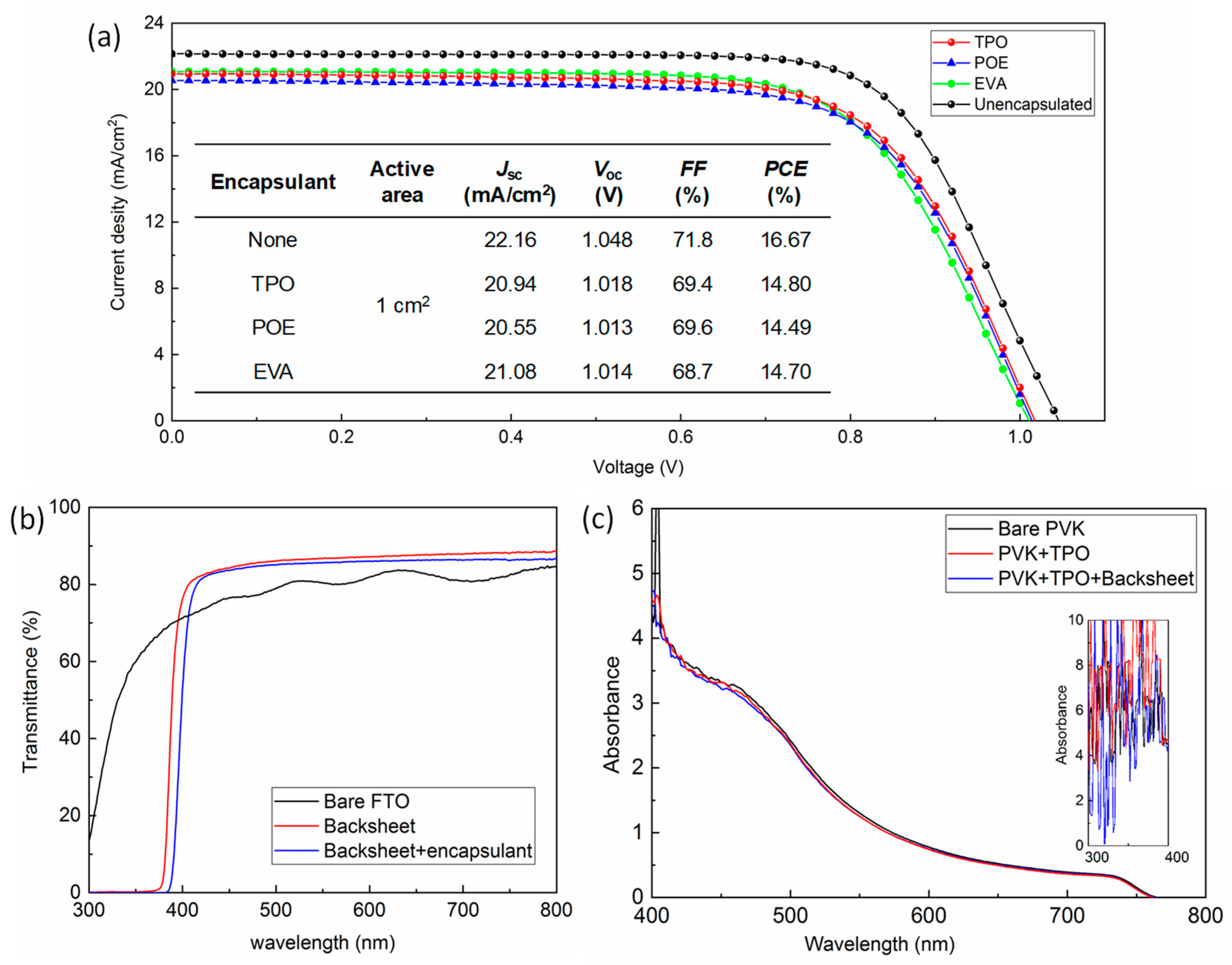
To evaluate the encapsulation effect on cell performance, the current density-voltage (J-V) curves of the PSCs before and after encapsulation with different materials were compared and are demonstrated in Figure 2a; the active area was 1 cm2, and the detailed photovoltaic parameters are displayed in the inset table. As a reference, a champion PCE of 19.48% was achieved on as-prepared cells with active area of 0.09 cm2 (J-V curve shown in Figure S2a), and the schematic diagram of each part of the cell, the mask for calibrating the active area, and the corresponding fabricated device are demonstrated in Figure S2b. Efficiency dropped to 16.67% as the area was expanded. After packaging with TPO, POE, and EVA, the remaining champion PCEs of the devices were 14.80%, 14.49%, and 14.70%, respectively. The statistical deviation of the photovoltaic parameters obtained for the devices with different encapsulants is displayed in Figure S3 and Table S1. The cells for all the groups retained around 87~89% of the initial output after packaging. Concluded from the variation of each parameter, including short-circuit current density (Jsc), open-circuit voltage (Voc), and fill factor (FF), the downtrend of Jsc value was the most obvious. To further investigate the influence of the additional backsheet as well as heat-curing encapsulant, we measured the corresponding transmittance, as exhibited in Figure 2b, and it could be observed that the bare backsheet possessed a high transmittance of over 80% value, from 400 to 820 nm. Interestingly, the filtered part (<400 nm) of the light includes ultraviolet (UV) light, which is beneficial for enhancing the durability of PSCs against the UV irradiation under practical operation [29]. When the laminated encapsulant was attached, the spectrum shifted towards the long wavelength direction, and transmittance was slightly reduced, ranging from 450 to 800 nm. The comparison of the absorbance of bare perovskite film on FTO before and after covering the encapsulation accessories is shown in Figure 2c (test diagram can be seen in Figure S4); the absorption of perovskite films seems to have an insignificant decline from 400 to 600 nm after TPO encapsulation and TPO plus backsheet. The absorbance before 400 nm (seen in the inset of Figure 2c) was unable to analyze probably due to equipment noise, and the FTO glass might also interfere with the absorption signal. It should be mentioned that the surface of backsheet was actually frosted, which helps improve the light trapping for optimizing the light utilization for the perovskite film. As a result, we might conclude that the encapsulation accessories have a minor impact for the decrease of Jsc. On the other hand, the high temperature during lamination that influenced the contact of copper sheet with Au electrode or the properties of organic materials might also cause the increment of contact resistance, leading to the reduction for all the parameters, especially the FF values [30].
The stability issue of the device was significantly ameliorated after encapsulation. We undertook a continuous observation on the PCE variation for PSCs, employing various encapsulants in different conditions. When the cells were kept in the glovebox, the PCE value demonstrated no attenuation within one month (seen in Figure S5), indicating our PSCs could maintain a fine durability in the absence of the strong interference of external factors. When it was placed in ambient air (humidity of around 60% and temperature of around 28 °C) and the corresponding J-V curves under 100 W/cm2 sunlight monitor irradiation at set intervals tested (shown in Figure 3a), the unencapsulated cell rapidly degraded within 2 days due to corrosion from the high concentration of oxygen as well as moisture, retaining only 11% of the initial PCE. Cells encapsulated by POE and EVA also exhibited inferior stability; their PCE all decayed to below 20% of the initial value within 8 days. As for TPO, it was inspiring to find that the packaged devices presented fine durability in ambient atmosphere, and the monitored PCE retained over 95% of the initial value after one month. Encapsulation of PSCs was mainly beneficial for enhancing the external stability of devices since it prevented the moisture and oxygen from entering the system; therefore, we further investigated the durability in a harsh environment by soaking the samples in water. Seen in the inset of Figure 3b, devices after TPO encapsulation demonstrated strong robustness after one week, and no obvious performance degradation was found.
To gain a more intuitive view on the device’s attenuation performance, we compared the cell morphology as well as crystallinity before and after aging (outdoor placement for 1000 h). As seen in Figure 4, the cross-sectional SEM (scanning electron microscope) images on the left demonstrated the encapsulated cell stored in the glovebox with dry N2. The perovskite film seemed to be intact and dense, indicating that no degradation occurred during the storage period. After aging, the SEM image of the TPO-encapsulated cell showed no obvious change despite the increased grain boundary quantity, which might be a result of light-induced degradation [14,31]. For EVA and POE groups, abundant pinholes appeared in perovskite bulk, and the gap between the perovskite layer and charge transport layer tended to be sharpened, inferring that both the perovskite film and interface encountered attenuation. SEM images for different groups from a broad view are exhibited in Figure S6. According to the previous report [32,33], the formation of pinholes in perovskite polycrystalline film could be mainly ascribed to the ingression for moisture and oxygen, which contributed to the transformation from cubic phase to monohydrate phase and then dehydration. This irreversible reaction tended to be more facilitated at the grain boundaries and interface, where higher density of the defects is likely to be present. Moreover, the ions migration driven by light and heat also contributed to the chain reaction, and consequently, the grains shrunk, and pinholes was observed. The phenomenon could also be coincidentally observed in XRD (X-ray diffraction), with the measured results shown in Figure 4e. Under the same aging procedure, as-prepared, as-encapsulated, and TPO-packed perovskite films after aging presented similar XRD patterns, indicating the perovskite films progressed few degradations when encapsulated by TPO initially and during the aging process. For POE groups, the peaks intensity at 19.9° corresponding to α-phase perovskite was significantly decreased, while peaks representing δ-phase perovskite at 11.8°, 20.6°, and 27.2° appeared [34]. The same situation was observed in EVA-encapsulated cells as well, which to a moderate extent agreed well with the relatively reduced pinholes. It was surprising to find that the PbI2 peak in the initial test became weak in other circumstances even when the films turned yellow (seen in Figure S7). We suspected there might be some internal reaction between materials released from encapsulant and PbI2, which possibly both existed in the first place and emerged during operation, forming an amorphous phase that was difficult to be detected [35].
We might explain the above observation from the perspective of material properties. EVA, polymerized by ethylene vinyl acetate, has always been the dominant encapsulant for silicon photovoltaic modules, with its appropriate properties of high transparency, excellent UV-light resistance, and fine adhesion with substrate. However, EVA will continuously degrade and release acetic acid during service [36], which is probably able to further react with perovskite components, leading to the decomposition of perovskite. On the other hand, due to the high sensitivity of perovskite to moisture, the corresponding applied encapsulant has more stringent requirements for the water vapor transmission rate (WVTR). The WVTR of EVA is around 24 g/(m2·d), while POE, as another maturely used encapsulant in industrial solar panels, provides a significant WVTR of 3 g/(m2·d). POE is cross-linked by olefin and therefore requires peroxidation as a crosslinking agent during the fabrication. The residential agent or the decomposed products of agent might cause the yellowing and thus lead to moisture intrusion. Some of the by-products can also react with active sections of PSCs, such as perovskite bulk and interfaces [37].
By contrast, TPO is prepared by copolymerizing of ethylene, a polar acrylate unit, and silane monomer. Although TPO has an inferior WVTR of 13 g/(m2·d) compared with POE, it demonstrates relatively higher chemical stability since no crosslinking procedure is required in the production, and nearly no by-products are released during the aging. Additionally, high temperature curing during lamination is not necessary for TPO. Generally, 115 to 125 °C is available for the encapsulation, and the relatively low-temperature procedure decreases the heat damage to the perovskite films. Moreover, TPO provides stronger adhesion strength to glass or backsheet (the adhesive force reaches 175.9 n/cm after laminating with glass), thus preventing moisture from entering the system through interlamination.
However, it has to be mentioned that the observation in our experiment does not mean that all the POE and EVA encapsulants are inappropriate for applying in PSCs. As described above, these encapsulation materials involve additives during the production, some of which might be released during the aging, while some others can increase the chemical reliability itself. The effectiveness of capsulation is also related to the device design, including the transporting layers applied, perovskite composition, and encapsulation mode. For instance, the study group of McGehee encapsulated PSCs in soft EVA and POE [25,38], enabling the devices to surpass the relative industry standard International Electrotechnical Commission (IEC), while Han et al. employed EVA as well as POE in packaging the printable mesoscopic PSC submodules and exhibited their inferior stability performance due to a high laminating temperature or corrosion of the perovskite absorber [26].
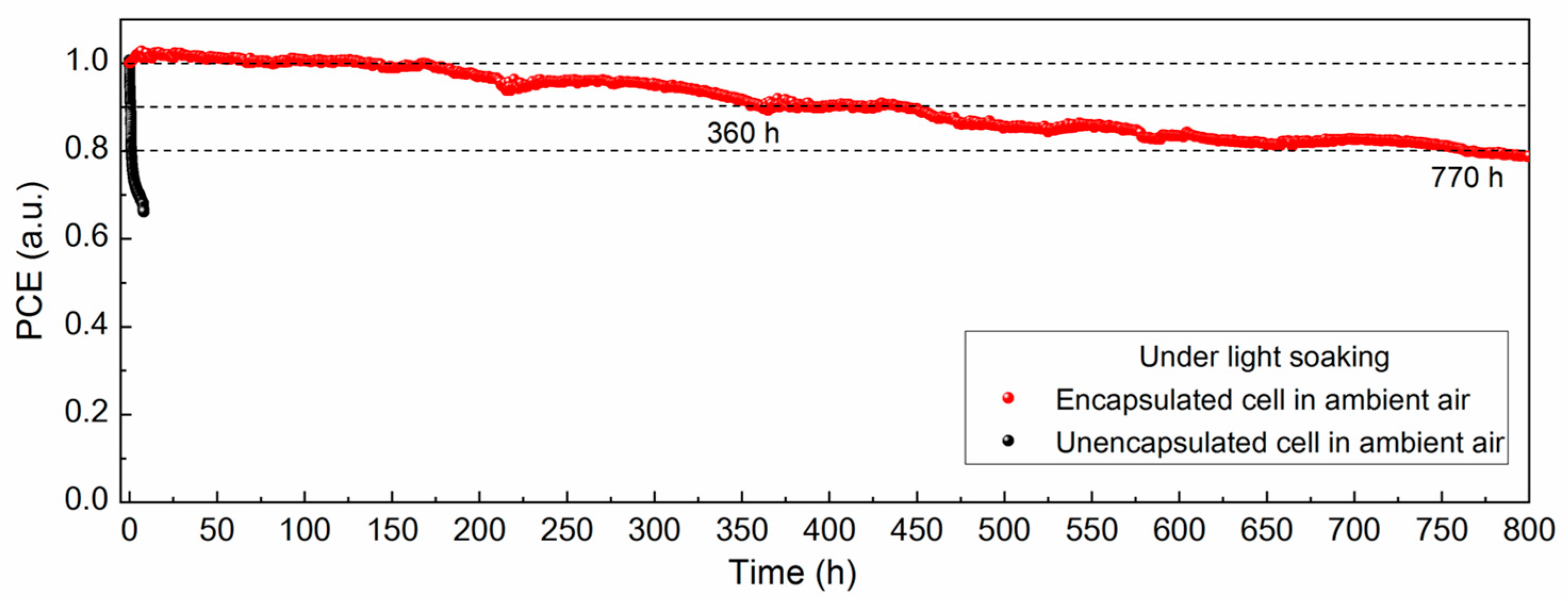
The device stability was also investigated under light soaking conditions at maximum power point tracking for monitoring the real working conditions; the testing environment can be seen in Figure S8, and the result is presented in Figure 5. As a comparison, the unsealed devices in ambient air showed a sharp decline in cell performance, preserving only ≈66% of the initial efficiency within 10 h of continuous light illumination. In contrast, for TPO-encapsulated cells, the lifespan of the cell kept in ambient air was significantly improved, and the power output was slightly increased in the initial observation period, which might be ascribed to the lattice expansion during the storage as well as ion migration effect under light-driven conditions [39,40,41]. Then, it maintained 90% of the initial value until 360 h and 80% of the value until 770 h. Apart from the external factors, internal causes including ionic migration, interface attenuation, metal electrode diffusion, etc., contributed to the output reduction as well. Therefore, we consider the encapsulation method to be an effective solution for outdoor operation of PSCs, and the next step of our work will be focused on strengthening the device reliability by modifying the film quality, regulating the perovskite composition, and passivating the interface and grain boundaries [42].

4. Conclusions

In summary, we herein demonstrate a facile approach for encapsulating PSCs at low temperature with conductive ribbons and PET backsheets on both sides. By introducing TPO as the encapsulant, the encapsulated PSCs exhibit strong reliability in ambient conditions, water soaking, and light soaking in operation (keeping 90% of the initial value until 360 h and 80% of the value until 770 h), which is ascribed to the low water vapor transmission rate and high chemical stability. We regard this encapsulation solution as providing a promising prospect for the commercialization of perovskite-based photovoltaic devices in the future.

Supplementary Materials

The following supporting information can be downloaded at: https://www.mdpi.com/article/10.3390/en16020598/s1.

Author Contributions

Y.X. and R.X. proposed the research, designed the experiments, carried out the experiments, and fabricated the solar cells; R.X. wrote the manuscript; J.G. and J.Z. helped with writing and revising the manuscript; W.X. and S.W. contributed to the characterization and analysis; R.X., N.Y. and J.D. supervised the work. All authors have read and agreed to the published version of the manuscript.

Funding

This research received external funding from the Natural Science Foundation of Jiangsu Province (BK20200187), the Special fund for Science and technology innovation of Jiangsu Province (BE2022610), Science and Technology Support Plan (Industrial) Project of Changzhou City (CE20220032), and Jiangsu Provincial “333” High-level Talent Training Project. The research leading to these results has also received funding from China Postdoctoral Science Foundation (2022M712341) and Jiangsu Planned Projects for Postdoctoral Research Funds (2021K084A).

Data Availability Statement

All data are contained within the article.

Conflicts of Interest

The authors declare no conflict of interest.

References

  1. Kojima, A.; Teshima, K.; Shirai, Y.; Miyasaka, T. Organometal Halide Perovskites as Visible-Light Sensitizers for Photovoltaic Cells. J. Am. Chem. Soc. 2009, 131, 6050–6051. [Google Scholar] [CrossRef] [PubMed]
  2. Sessolo, M.; Bolink, H.J. Hovering Solar Cells. Nat. Mater. 2015, 14, 964–966. [Google Scholar] [CrossRef] [PubMed]
  3. NREL. Best Research-Cell Efficiencies. Available online: https://www.nrel.gov/pv/assets/images/efficiency-chart.png (accessed on 1 December 2022).
  4. Green, M.A.; Ho-Baillie, A.; Snaith, H.J. The Emergence of Perovskite Solar Cells. Nat. Photonics 2014, 8, 506–514. [Google Scholar] [CrossRef]
  5. Mitzi, D.B. Introduction: Perovskites. Chem. Rev. 2019, 119, 3033–3035. [Google Scholar] [CrossRef] [Green Version]
  6. Wang, D.; Wright, M.; Elumalai, N.K.; Uddin, A. Stability of Perovskite Solar Cells. Sol. Energy Mater. Sol. Cells 2016, 147, 255–275. [Google Scholar] [CrossRef]
  7. Wang, Q.; Phung, N.; Di Girolamo, D.; Vivo, P.; Abate, A. Enhancement in Lifespan of Halide Perovskite Solar Cells. Energy Environ. Sci. 2019, 12, 865–886. [Google Scholar] [CrossRef]
  8. Beal, R.E.; Slotcavage, D.J.; Leijtens, T.; Bowring, A.R.; Belisle, R.A.; Nguyen, W.H.; Burkhard, G.F.; Hoke, E.T.; McGehee, M.D. Cesium Lead Halide Perovskites with Improved Stability for Tandem Solar Cells. J. Phys. Chem. Lett. 2016, 7, 746–751. [Google Scholar] [CrossRef]
  9. Lee, J.-W.; Park, N.-G. Chemical Approaches for Stabilizing Perovskite Solar Cells. Adv. Energy Mater. 2020, 10, 1903249. [Google Scholar] [CrossRef]
  10. Lv, Y.; Xu, P.; Ren, G.; Chen, F.; Nan, H.; Liu, R.; Wang, D.; Tan, X.; Liu, X.; Zhang, H.; et al. Low-temperature Atomic Layer Deposition of Metal Oxide Layers for Perovskite Solar Cells with High Efficiency and Stability under Harsh Environmental Conditions. ACS Appl. Mater. Interfaces 2018, 10, 23928–23937. [Google Scholar] [CrossRef]
  11. Sepalage, G.A.; Weerasinghe, H.; Rai, N.; Duffy, N.W.; Raga, S.R.; Hora, Y.; Gao, M.; Vak, D.; Chesman, A.S.R.; Bach, U.; et al. Can Laminated Carbon Challenge Gold? Toward Universal, Scalable, and Low-Cost Carbon Electrodes for Perovskite Solar Cells. Adv. Mater. Technol. 2022, 7, 2101148. [Google Scholar] [CrossRef]
  12. Kranthiraja, K.; Parashar, M.; Mehta, R.K.; Aryal, S.; Temsal, M.; Kaul, A.B. Stability and Degradation in Triple Cation and Methyl Ammonium Lead Iodide Perovskite Solar Cells Mediated via Au and Ag Electrodes. Sci. Rep. 2022, 12, 18574. [Google Scholar] [CrossRef] [PubMed]
  13. Kranthiraja, K.; Arivunithi, V.M.; Aryal, U.K.; Park, H.-Y.; Cho, W.; Kim, J.; Reddy, S.S.; Kim, H.-K.; Kang, I.-N.; Song, M.; et al. Efficient and Hysteresis-Less Perovskite and Organic Solar Cells by Employing Donor-Acceptor Type π-conjugated Polymer. Org. Electron. 2019, 72, 18–24. [Google Scholar] [CrossRef]
  14. Wang, Z.; Zhang, Z.; Xie, L.; Wang, S.; Yang, C.; Fang, C.; Hao, F. Recent Advances and Perspectives of Photostability for Halide Perovskite Solar Cells. Adv. Optical Mater. 2022, 10, 2101822. [Google Scholar] [CrossRef]
  15. Li, M.; Yan, X.; Kang, Z.; Huan, Y.; Li, Y.; Zhang, R.; Zhang, Y. Hydrophobic Polystyrene Passivation Layer for Simultaneously Improved Efficiency and Stability in Perovskite Solar Cells. ACS Appl. Mater. Interfaces 2018, 10, 18787–18795. [Google Scholar] [CrossRef] [PubMed]
  16. Asghara, M.I.; Zhang, J.; Wang, H.; Lund, P.D. Device Stability of Perovskite Solar Cells—A Review. Renew. Sust. Energy Rev. 2017, 77, 131–146. [Google Scholar] [CrossRef] [Green Version]
  17. Lee, Y.I.; Jeon, N.J.; Kim, B.J.; Shim, H.; Yang, T.-Y.; Seok, S.I.; Seo, J.; Im, S.G. A Low-temperature Thin-film Encapsulation for Enhanced Stability of a Highly Efficient Perovskite Solar Cell. Adv. Energy Mater. 2018, 8, 1701928. [Google Scholar] [CrossRef]
  18. Li, J.; Xia, R.; Qi, W.; Zhou, X.; Cheng, J.; Chen, Y.; Hou, G.; Ding, Y.; Li, Y.; Zhao, Y.; et al. Encapsulation of Perovskite Solar Cells for Enhanced Stability: Structures, Materials and Characterization. J. Power Sources 2021, 485, 229313. [Google Scholar] [CrossRef]
  19. Yuan, Y.; Huang, J. Ion Migration in Organometal Trihalide Perovskite and Its Impact on Photovoltaic Efficiency and Stability. Acc. Chem. Res. 2016, 49, 286–293. [Google Scholar] [CrossRef] [Green Version]
  20. Uddin, A.; Upama, M.B.; Yi, H.; Duan, L. Encapsulation of Organic and Perovskite Solar Cells: A Review. Coatings 2019, 9, 65. [Google Scholar] [CrossRef] [Green Version]
  21. Kang, H.; Kim, G.; Kim, J.; Kwon, S.; Kim, H.; Lee, K. Bulk-heterojunction Organic Solar Cells: Five Core Technologies for Their Commercialization. Adv. Mater. 2016, 28, 7821–7861. [Google Scholar] [CrossRef]
  22. Cros, S.; De Bettignies, R.; Berson, S.; Bailly, S.; Maisse, P.; Lemaitre, N.; Guillerez, S. Definition of Encapsulation Barrier Requirements: A Method Applied to Organic Solar Cells. Sol. Energy Mater. Sol. Cells 2011, 95, S65–S69. [Google Scholar] [CrossRef]
  23. Ma, S.; Yuan, G.; Zhang, Y.; Yang, N.; Li, Y.; Chen, Q. Development of Encapsulation Strategies Towards the Commercialization of Perovskite Solar Cells. Energy Environ. Sci. 2022, 15, 13–55. [Google Scholar] [CrossRef]
  24. Dong, Q.; Liu, F.; Wong, M.K.; Tam, H.W.; Djurišić, A.B.; Ng, A.; Surya, C.; Chan, W.K.; Ng, A.M.C. Encapsulation of Perovskite Solar Cells for High Humidity Conditions. ChemSusChem 2016, 9, 2597. [Google Scholar] [CrossRef] [PubMed]
  25. Cheacharoen, R.; Boyd, C.C.; Burkhard, G.F.; Leijtens, T.; Raiford, J.A.; Bush, K.A.; Bent, S.F.; McGehee, M.D. Encapsulating Perovskite Solar Cells to Withstand Damp Heat and Thermal Cycling. Sustain. Energy Fuels 2018, 2, 2398–2406. [Google Scholar] [CrossRef]
  26. Fu, Z.; Xu, M.; Sheng, Y.; Yan, Z.; Meng, J.; Tong, C.; Li, D.; Wan, Z.; Ming, Y.; Mei, A.; et al. Encapsulation of Printable Mesoscopic Perovskite Solar Cells Enables High Temperature and Long-Term Outdoor Stability. Adv. Funct. Mater. 2019, 29, 1809129. [Google Scholar] [CrossRef]
  27. Shi, L.; Zhang, M.; Cho, Y.; Young, T.L.; Wang, D.; Yi, H.; Kim, J.; Huang, S.; Ho-Baillie, A.W.Y. Effect of Pressing Pressure on the Performance of Perovskite Solar Cells. ACS Appl. Energy Mater. 2019, 2, 2358–2363. [Google Scholar] [CrossRef]
  28. Salado, M.; Payno, D.; Ahmad, S. Enhancing Operational Stability in Perovskite Solar Cells by Solvent-free Encapsulation Method. Sustain. Energy Fuels 2022, 6, 2264–2275. [Google Scholar] [CrossRef]
  29. Fu, Q.; Tang, X.; Huang, B.; Hu, T.; Tan, L.; Chen, L.; Chen, Y. Recent Progress on the Long-Term Stability of Perovskite Solar Cells. Adv. Sci. 2018, 5, 1700387. [Google Scholar] [CrossRef]
  30. De Bastiani, M.; Babics, M.; Aydin, E.; Subbiah, A.S.; Xu, L.; De Wolf, S. All Set for Efficient and Reliable Perovskite/Silicon Tandem Photovoltaic Modules? Sol. RRL 2022, 6, 2100493. [Google Scholar] [CrossRef]
  31. Wen, J.; Zhao, Y.; Liu, Z.; Gao, H.; Lin, R.; Wan, S.; Ji, C.; Xiao, K.; Gao, Y.; Tian, Y.; et al. Steric Engineering Enables Efficient and Photostable Wide-Bandgap Perovskites for All-Perovskite Tandem Solar Cells. Adv. Mater. 2022, 34, 2110356. [Google Scholar] [CrossRef]
  32. Mosconi, E.; Azpiroz, J.M.; De Angelis, F. Ab Initio Molecular Dynamics Simulations of Methylammonium Lead Iodide Perovskite Degradation by Water. Chem. Mater. 2015, 27, 4885–4892. [Google Scholar] [CrossRef]
  33. Wang, Q.; Chen, B.; Liu, Y.; Deng, Y.; Bai, Y.; Dong, Q.; Huang, J. Scaling Behavior of Moisture-Induced Grain Degradation in Polycrystalline Hybrid Perovskite Thin Films. Energy Environ. Sci. 2017, 10, 516–522. [Google Scholar] [CrossRef]
  34. Liu, D.; Wang, S.; Xia, R.; Xu, Y.; Gu, L.; Li, R.; Fang, X.; Hu, H.; Yuan, N.; Ding, J. Post-Treating the Precursor Intermediate Film by a Cooling Stage for Fabricating Efficient Formamidinium-Based Perovskite Solar Cells. ACS Appl. Mater. Interfaces 2021, 13, 11783–11792. [Google Scholar] [CrossRef]
  35. Ono, L.K.; Juarez-Perez, E.J.; Qi, Y. Progress on Perovskite Materials and Solar Cells with Mixed Cations and Halide Anions. ACS Appl. Mater. Interfaces 2017, 9, 30197–30246. [Google Scholar] [CrossRef] [Green Version]
  36. Kempe, M.D.; Jorgensen, G.J.; Terwilliger, K.M. Ethylene-vinyl Acetate Potential Problems for Photovoltaic Packaging. Sol. Energy Mater. Sol. Cells 2007, 91, 315–329. [Google Scholar] [CrossRef]
  37. Li, B.; Wang, M.; Subair, R.; Cao, G.; Tian, J. Significant Stability Enhancement of Perovskite Solar Cells by Facile Adhesive Encapsulation. J. Phys. Chem. C 2018, 122, 25260–25267. [Google Scholar] [CrossRef]
  38. Cheacharoen, R.; Rolston, N.; Harwood, D.; Bush, K.A.; Dauskardt, R.H.; McGehee, M.D. Design and Understanding of Encapsulated Perovskite Solar Cells to Withstand Temperature Cycling. Energy Environ. Sci. 2018, 11, 144–150. [Google Scholar] [CrossRef]
  39. Zhang, Y.; Zhu, Y.; Hu, M.; Pai, N.; Qin, T.; Cheng, Y.; Bach, U.; Simonov, A.N.; Lu, J. Self-Enhancement of Efficiency and Self-Attenuation of Hysteretic Behavior of Perovskite Solar Cells with Aging. J. Phys. Chem. Lett. 2022, 13, 2792–2799. [Google Scholar] [CrossRef]
  40. Zhang, X.; Wei, S.-H. Origin of Efficiency Enhancement by Lattice Expansion in Hybrid-Perovskite Solar Cells. Phys. Rev. Lett. 2022, 128, 136401. [Google Scholar] [CrossRef]
  41. Deng, Y.; Xiao, Z.; Huang, J. Light-Induced Self-Poling Effect on Organometal Trihalide Perovskite Solar Cells for Increased Device Efficiency and Stability. Adv. Energy Mater. 2015, 5, 1500721. [Google Scholar] [CrossRef]
  42. Chi, W.; Banerjee, S.K. Stability Improvement of Perovskite Solar Cells by Compositional and Interfacial Engineering. Chem. Mater. 2021, 33, 1540–1570. [Google Scholar] [CrossRef]
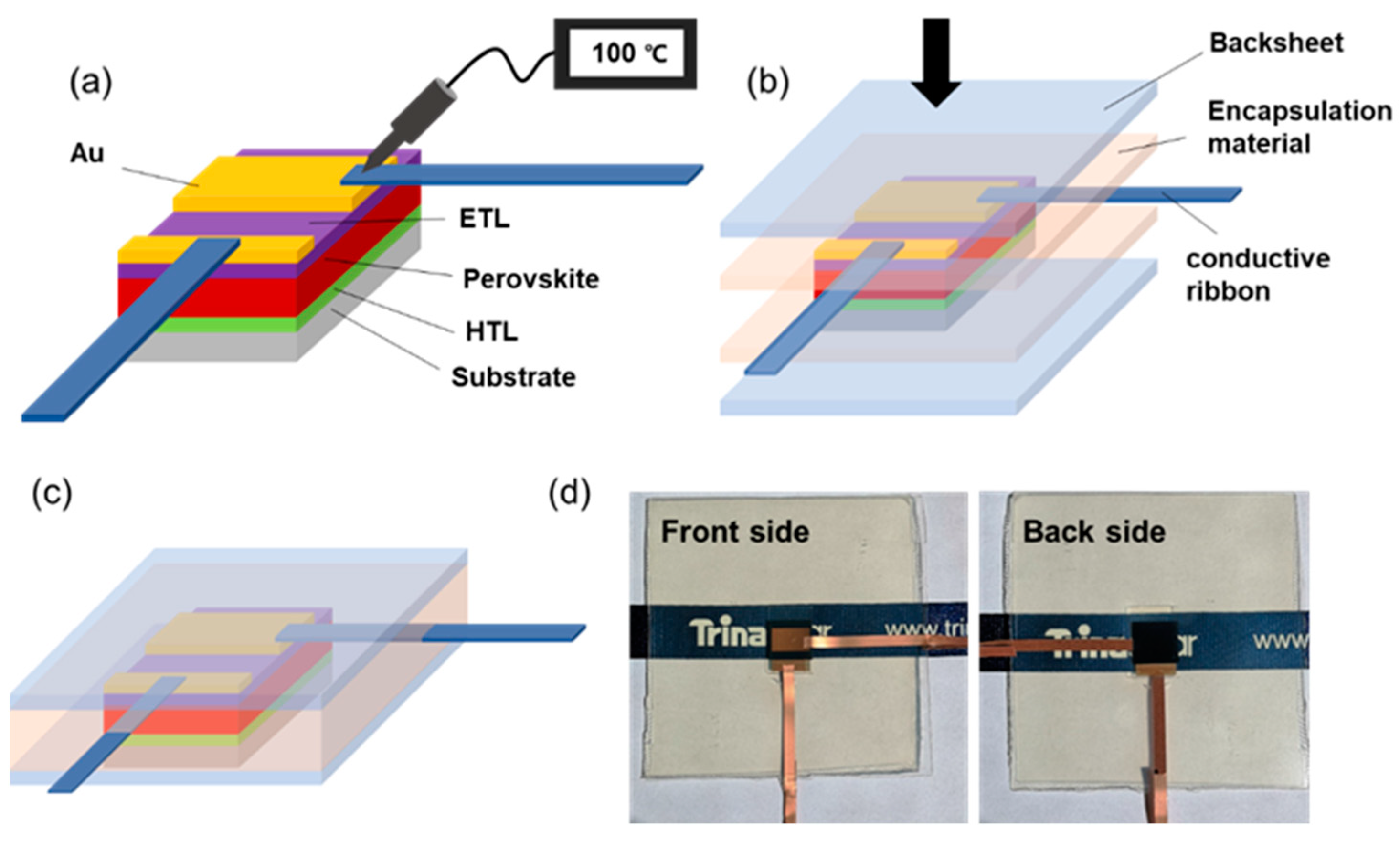
Figure 1. (ac) The diagrammatic sketch of encapsulation procedure. (d) The digital photos of encapsulated PSC.
Energies 16 00598 g001
Figure 2. (a) J-V curve of the PSCs before and after encapsulation with different materials. (b) The transmittance of FTO, backsheet, and backsheet overlay with encapsulant. (c) Absorption spectra of bare perovskite film, perovskite films/laminated TPO, and perovskite/laminated TPO/backsheet.
Energies 16 00598 g002
Figure 3. (a) The stability of PSCs in ambient conditions encapsulated with different materials; (b) the normalized PCE variation of PSC encapsulated with TPO immersed in water.
Energies 16 00598 g003
Figure 4. SEM images of (a) as-prepared PSC and encapsulated PSC with (b) TPO, (c) POE, and (d) EVA after aging. The scale bar is 500 nm. (e) XRD patterns of perovskite films on FTO substrates encapsulated with different materials before and after aging.
Energies 16 00598 g004
Figure 5. Evolution of the normalized PCE for cells with and without encapsulation under light soaking.
Energies 16 00598 g005
Disclaimer/Publisher’s Note: The statements, opinions and data contained in all publications are solely those of the individual author(s) and contributor(s) and not of MDPI and/or the editor(s). MDPI and/or the editor(s) disclaim responsibility for any injury to people or property resulting from any ideas, methods, instructions or products referred to in the content.