Abstract
The operating license of Kori units 3 and 4 are to be expired in 2024 and 2025. If the plants are decided to be decommissioned, the spent nuclear fuels in the spent fuel storage pool (SFP) have to be removed from the site. However, no proper storage facility is currently available in Korea. To overcome the difficulty, this study proposes application of an independent temporary SFP cooling system. It is expected to safely isolate the SFP from the plant. The case study conducted showed this concept is achievable and technically mature. Moreover, the installation cost per unit is USD 9.51 million obtained from an analogous estimating. This is much lower cost than the dry cask options. Then, system requirements and applicable design are developed. Maximum heat generation of unit 4 is estimated as 1.67 MW, through fuel characteristics categorizations and ORIGEN calculations. To remove the decay heat, installation of an indirect air-cooled method is selected by evaluating three cooling methods. The modification includes new heat exchanger, secondary cooling pumps, and chillers. Furthermore, two single failures are considered; cooling pump and normal power. This can be covered by two redundant trains and a back-up diesel generator provided.
1. Introduction
Nuclear energy has been providing a safe, stable, and economic source of electricity in Korea. Now, some early nuclear power plants are reaching end of the design life. For example, Kori units 3 and 4 are 950 MW pressurized water reactor plants. They started commercial operation in 1985 and 1986, so the validity of the current operating licenses will end in 2024 and 2025. The plants may shut down permanently for decommissioning or may continue the operation through the operating license renewal process. In any case, it is important to establish a proper spent nuclear fuel (SNF) management plan as early as possible. Particularly, temporary storage for the spent nuclear fuels has to be prepared before the decommissioning activities. Spent nuclear fuels emit high level of radiation and decay heat. Therefore, they have to be removed before the decommissioning activities to support the radiation safety of the workers and an efficient decommissioning project management. However, currently no available storage facility can be found in Korea. According to a recent plan, preparation of an interim storage would take 20 years, and that of a permanent disposal facility would take 37 years [1]. Furthermore, utilizing dry storages may have potential difficulties due to a limited supply of the casks and the opposition of the people.
One alternative to overcome this difficulty is a temporary SFP cooling system independently operated from the plant. The essential concept of this system is to isolate the spent fuel storage pool from the plant systems while the spent nuclear fuels are being stored inside. Therefore, the system is required to provide radiation shielding and cooling for the spent nuclear fuels. In addition, the components are mechanically and electrically independent to other systems, so other parts of the plant can be decommissioned. This can be achieved by modifying current SFP cooling system.
SFP cooling system in the normal operating condition is the spent fuel pool cooling and cleanup system (SFPCCS). The design basis of the SFPCCS specifies cooling capacity for a normal operation and residual heat, single failure, earthquake, and inspection. The summary of the SFPCCS system design basis are listed in Table 1 [2].

Table 1.
System design basis of SFPCCS.
Schematic of the primary loop of SFP cooling system in normal operating condition is shown in Figure 1. To comply with the system design basis, the SFPCCS is composed of two redundant trains. Each train has two closed-loops; primary and secondary loop. Primary loop transfers the decay heat to the heat exchanger. Secondary loop receives the heat through the heat exchanger. Then, the secondary loop dissipates heat to the ultimate heat sink through the component cooling water system (CCWS) and the nuclear service cooling water system (NSCWS).
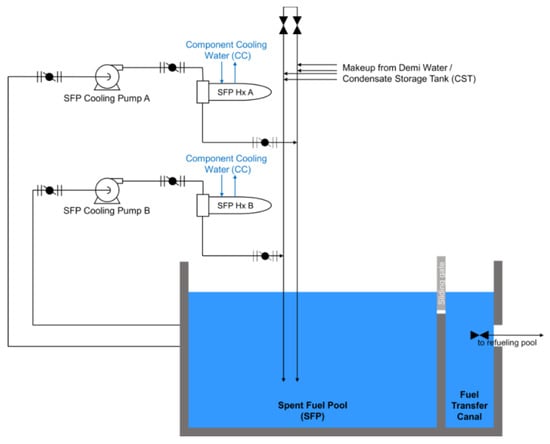
Figure 1.
Schematic of current SFPCCS.
On the other hand, a study estimated the costs for a spent fuel pool island (SFPI), concrete casks, metal casks, and duel-purpose casks. The SFPI is one application of the temporary SFP cooling system in the U.S. The cost analysis included the inflated, escalated, and discounted costs for the installation and 10 years of operation and maintenance (O&M). The results indicate an economic advantage of the SFPI application compared to the dry storage options as shown in Table 2 [3].
Table 2.
Comparison of estimated total costs for SFPI and dry casks.
The cost is often estimated by directly looking at the proportion of the project sizes. In this case, applying accurate input parameter becomes significantly important. As the cooling performance is the main function of the system, it is reasonable to assume the cooling capacity is proportional to the project size. Therefore, properly estimated cooling capacity would provide more accurate results.
A study conducted in 2021 evaluated decay heat of Kori units 3 and 4. ORIGEN of SCLAE 6.2 developed by Oak Ridge National Laboratory (ORNL) was mainly used. The calculation results are shown in Table 3 [4].
Table 3.
Estimated total decay heat of Kori units 3 and 4.
This study very broadly categorized the spent nuclear fuels. For this reason, it may not reflect the realistic conditions of the characteristics of the spent nuclear fuels in the pool. Hence, more accurate conditions can be applied to obtain more accurate results.
The purpose of this study is to investigate application of a temporary SFP cooling system for decommissioning of Kori units 3 and 4. This begins with a feasibility study covering technical, political, and economic aspects. Then, the system requirements of the temporary SFP cooling system are discussed. Maximum decay heat is estimated to decide the cooling capacity. In addition, possible single failure scenarios are developed. Finally, three alternatives are listed and evaluated for cooling the spent nuclear fuels in the pool. All alternatives have been successfully practiced in other decommissioning sites. For the evaluation process, five main criteria are sorted which show significance and clear dissimilarity among alternatives. Then, configuration of an applicable system design is suggested. In addition, major components are listed and required capacities of the components are estimated.
2. Feasibility
2.1. Case Study
A case study has been conducted on the similar practices in the U.S. This work is mainly to observe whether the technology is mature enough to be achievable in Korea. For this, conditions of the SFP, cooling methods, and configurations of the system are investigated. All plants studied had pressurized water reactors and similar plant configurations to Kori units 3 and 4.
2.1.1. SONGS Units 2&3
The SONGS units 2 and 3 were located in San Clemente, California. The reactor types were pressurized water reactors with the thermal and electrical capacity of 3438 MWt and 1127 MWe. The plants had been operated since 1982, and permanently ceased the operation in 2013. For the decommissioning of the plants, independent spent fuel pool cooling system (ISFPCS) was introduced. The main purpose of the ISFPCS was to temporarily store the spent nuclear fuels for decommissioning until the spent nuclear fuels would be safely transferred to the on-site dry casks, also known as independent spent fuel storage installation (ISFSI). The location of ISFPCS components was behind the spent fuel buildings, outside of the containments and other plant buildings.
At the permanent shutdown, 1318 spent nuclear fuel assemblies were stored in the unit 2 SFP and 1350 spent nuclear fuel assemblies were stored in the unit 3 SFP. The maximum decay heat load generated from the spent fuel assemblies was reported as 2.36 MBtu/h (0.692 MW) in 30 June 2016, including additional contingency dry storage canister (DSC) offload of 0.127 MBtu/h (0.0372 MW). To measure the heat load of the pool, NUREG-0800, Residual Decay Energy for Light Water Reactors for Long Term Cooling, was referenced. 10% of uncertainty factor was considered, and conservative outside air temperature was assumed as 120 °F (48.9 °C) while maximum actual temperature was recorded as 108 °F (42.2 °C). The maximum decay heat load could be well covered by the ISFPCS capacity of 3.0 MBtu/h (0.879 MW), with the 2.4 MBtu/h (0.703 MW) of single chiller installed [5].
The ISFPCS consists of two closed loops; a primary cooling loop and a secondary cooling loop. A purification line is attached on the primary cooling loop. The ultimate heat sink is provided by the outdoor air through additionally installed chillers on the secondary cooling loop.
On the primary cooling loop, major components are two 100% capacity pumps and a 100% capacity plate type heat exchanger. To achieve a higher efficiency, the original heat exchanger was replaced. The new heat exchanger was a plate type which generally shows a higher efficiency than a shell-tube type. Also, two ion exchangers (IXs) are provided to purify the cooling water of the primary cooling loop. The major components of the secondary cooling loop are two 100% capacity pumps and a 200-ton chiller. There is an additional chiller commonly used by both units, in the case of a component failure or maintenance. Hence, total three chillers are installed for two units.
To monitor the operating parameters of the ion exchangers, local sample points are provided. In addition, temporary submersible purification system is provided when the primary purification system unavailable. An air compressor is equipped for providing motive force of the priming pump, operating IX air operated valves (AOVs), and pressurizing the secondary cooling loop surge tank bladder. Furthermore, a back-up diesel generator is provided in a case of a power failure. This is installed to support essential bus as an emergency electricity source. The design classes of ISFPCS are Quality Class III-AQ and Seismic Category III [5].
2.1.2. Maine Yankee
Maine Yankee was a single unit nuclear power plant located in Wiscasset, Maine. The size of the reactor was 900 MW, and operated from 1972 through 1996. The plant permanently shut down in 1997. There was a replacement of the air-cooler fans due to an increased level of noise. The cost for the replacement was reported as about USD 160,000, and the modification was completed in 1998 [6].
System requirements of the SFPI was to remove the maximum heat load of 3.3 MBtu/h and the maximum heat-up rate without cooling of 1.08 °F/h [5]. Hence, the amount of the maximum decay heat estimated is close to those of the Kori units and the SONGS units.
The major components are two cooling pumps, a SFP heat exchanger, and the fan-powered air coolers. The location of the coolers is outside of the plant building. The major cleanup components of the SFPI are surface skimmers, a purification pump, filters, and a mixed bed demineralizer. In addition, a diesel generator was prepared as a back-up power supply.
2.1.3. Trojan
Trojan NPP was located Columbia County, Oregon. Capacity of the reactor was 1130 MW. The plant had been mostly owned by Portland General Electric (PGE). Trojan NPP started its commercial operation in 1976, and the plant was permanently shut down for decommissioning in 1993. The spent nuclear fuels had been stored in the SFP, and the 791 spent nuclear fuel assemblies were transferred to 34 dry casks of the ISFSI site in 2003. The spent nuclear fuels will remain at the Trojan site until the federal government takes them to place at a central storage facility.
The actual decay heat was initially about 3.4 MBtu/h, but it becomes about 0.9 Mbtu/hr five years later. To remove the decay heat, modular SFP cooling and cleanup system is used. The system adopted a direct air-cooled modular chiller. In addition, the modular chiller system was leased from a qualified vendor. [6]. The main components of the modular cooling system are two 100% cooling pumps to circulate the SFP cooling water, a filter, a demineralizer, and two air coolers. The cooling pumps are centrifugal type with 250 gpm at 160 feet of head [7]. The modular SFP cooling and cleanup system is a simpler system with the lowest expected capital cost compared to other alternatives. However, the maximum heat load of Trojan NPP is smaller than other SFPI cases. Hence, the temporary SFP cooling system for Kori units 3 and 4 should be designed for a greater heat removal capacity.
2.2. Cost Analysis
2.2.1. Installation Cost
A report estimated the installation cost of ISFPCS of SONGS units 2 and 3 as shown in Table 4 [8]. The total installation costs for the units are estimated as about 8.54 million U.S. dollars. The cost for one unit can be obtained by halving the total cost; which is obtained as 4.27 million U.S. dollars in 2017.
Table 4.
Estimated installation costs for ISFPCS.
An analogy cost estimating technique is based on the actual historical data, and provides quick, readily understood, and accurate for minor deviations from the analog [9]. As the plants share similar conditions, the deviations required for the temporary SFP cooling system of Kori units 3 and 4 will be limited from other previous practices in the U.S. In addition, many parameters are still not decided for the temporary SFP cooling system. Hence, an analogy cost estimating technique is expected to yield comparatively reliable results under given conditions. Generally, an analogy estimating can be performed by Equation (1). The scale factor, x, indicates the economies of scale. Scale factor can be neglected as the cost for equipment is likely to show linear increment to the heat load capacity [10]. Generally, the price of chiller proportionally increases based on the capacity increases according to a report of the industry [11]. Therefore, it is assumed that the value for the scale factor is set as one in this cost estimating process.
where C2 is the cost of Project 2 to be estimated with known capacity Q2, C1 is the known cost of Project 1 with capacity Q1, Q2 is the known capacity of Project 2, Q1 is the known capacity of Project 1.
In the case of SONGS units 2 and 3, the total cost for the ISFPCS installation was estimated as 4.27 million dollars per unit. The maximum heat load recorded was 3.0 MBtu/h (0.879 MW). The maximum heat load of Kori units 3 and 4 estimated in this study of this study is 1.67 MW (5.68 MBtu/h). Then, the estimated installation cost for the temporary SFP cooling system is obtained as 8.08 million U.S. dollars. However, the result reflects the price in 2017. Hence, the inflation rates have to be applied to yield the cost in the year of the project starts. As the operating licenses of Kori units 3 and 4 end in 2024 and 2025, it is assumed that the project for installing the temporary SFP cooling system starts in 2024 and 2025.
Producer price index (PPI) including goods and services can be the most adequate reference in this case. The average annual inflation can be calculated by Equation (2).
where iη is the average annual inflation rate of the year, and Pη is the producer price index in the year. The producer price index and average annual inflation of goods and services provided by Bank of Korea is shown in Table 5. From the information, the average of the producer price index in the recent five years is calculated as 2.26%.
Table 5.
Producer price index and average annual inflation in Korea.
Now, the price considering inflation can be calculated by Equation (3).
where xη is the estimated cost in year η, and iη is the average annual inflation rate in year η. The inflation rates of the years after 2021 are assumed the same as that in 2021. Now, the net positive value (NPV) of the installation cost in each year is obtained as shown in Table 6.
Table 6.
Result of installation cost estimation.
Therefore, the installation cost for the temporary SFP cooling system for each unit is estimated as 9.51 million U.S. dollars in year 2025.
2.2.2. Operating Cost
Korea Hydro and Nuclear Power (KHNP) is a public enterprise that owns and operates the nuclear power plants in Korea. Before the termination of the operating license, KHNP will still have the ownership of the nuclear power plants. For this reason, KHNP will have the ownership and responsibility for operating the temporary SFP cooling system. It is difficult to estimate the operating cost because most operating cost data of KHNP is not disclosed to the public. Also, many types of fixed cost; for example, insurance, taxes, salaries, utility expenses, and legal expenses, are combined with the operating costs for the plant. However, the operating cost can be reasonably small because most fixed costs are already included. Moreover, the company has been developed useful resources including experienced employees, operating data and operating systems. This would support much more effective operation of the temporary SFP cooling system, and a smaller operating cost eventually.
3. System Requirements
3.1. Cooling Capacity
3.1.1. Decay Heat Estimation
Decay heat from the spent nuclear fuels has to be estimated to decide required cooling capacity of the system. It is assumed that no transportation of spent nuclear fuels with other plants as the exact transportation history is not available to the public. Another assumption made is that the spent fuel storage pool is fully saturated from the 40 years of operation. The spent nuclear fuels are assumed to have been uniformly generated every year. The maximum capacity of spent fuel storage pool of Kori units 3&4 is 2260 spent nuclear fuel assemblies [2]. Hence, it is assumed that the spent fuel storage pool is fully saturated with 2260 spent nuclear fuel assemblies at the point of the permanent shutdown. In addition, uniform generation rate of 56.5 spent nuclear fuel assemblies per year is assumed. In a study, annual spent nuclear fuel assemblies generated from Kori 3 and 4 was estimated as 22 MTHM equivalent to 52 fuel assemblies [12]. Therefore, 56.5 assemblies of annual generation can be a reasonably conservative value for the decay heat estimation.
On the other hand, as the nuclear fuel technology has been advanced for several decades, the commercial nuclear fuel models used in the plant have been changed. General trend acquired from the operating data of KHNP indicates a trend of increased burnup rate of the spent nuclear fuels. The graph of the average burn rates is shown in Figure 2.

Figure 2.
Average burnup rate trend of spent nuclear fuels of Kori units 3 and 4.
Majority of the nuclear fuel types used in Korea are Westinghouse standard fuel assembly (W-STD), Westinghouse optimized fuel assembly (W-OFA), Korean optimized fuel assembly (KOFA), robust fuel assembly (RFA), Vantage 5H, and ACE7 [13,14]. The summary of the nuclear fuel supply history is shown in Figure 3.
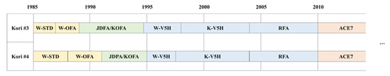
Figure 3.
Types of nuclear fuels supplied for Kori units 3 and 4.
Another study suggested a conservative approach to the reference burnup rate of spent nuclear fuel assemblies at 55 GWd/tU supported by the burnup rate prediction for the future fuels. The result of the burnup rate prediction showed in the range of 38.8~52.9 GWd/tU in 95% confidence interval [15]. On the other hand, another study presented that among the spent nuclear fuels stored in Korea, 99.8% of assemblies showed less than 55 GWd/tU burnup rate, and 85.2% of the spent nuclear fuel assemblies showed less than 45 GWd/tU [16].
From the data collected, seven representative spent nuclear fuel groups are created for more systematic approach. The burnup rates of each group is set to be higher than the maximum burnup rates of the nuclear fuel types to more conservatively assume the parameters. For example, burnup rate of 55 MWd/tU is decided for the spent nuclear fuel groups generated from 2010 to 2025. This is well higher value than the actual average burnup rate which generally does not exceed 50.0 MWd/tU from the operating data. For the same purpose, the shortest cooling times are considered for each group. Meanwhile, minimum five years of cooling time is assumed for all groups. The Korean government enforces the spent nuclear fuels to be cooled at least for five years before delivering [17]. Although the detailed guidelines have not been clearly decided, it is highly probable that five years of minimum cooling time will be also applied before a major modification on the spent fuel storage pool cooling system. Now, the summary of the representative spent nuclear fuel groups are shown in Table 7.
Table 7.
Representative spent nuclear fuel groups of Kori units 3&4.
Kori unit 4 will cease the operation one year after the shutdown of unit 3. Therefore, all spent nuclear fuels of unit 4 will experience shorter cooling time. For this reason, the value for estimated decay heat of unit 4 is used for the cooling capacity of the system, which is a more conservative value than that of unit 3. The maximum decay heat generated of unit 4 is estimated as 1.67 MW as shown in Table 8. This indicates 736.5 watt of decay heat generation per assembly. The actual maximum decay heat recorded in SONGS units 2&3 was 0.69 MW from 1350 assemblies, and this indicates that 512.3 watt of heat had been generated per assembly [5]. Therefore, the results present 44% greater decay heat estimation compared to the real case.
Table 8.
Estimated total decay heat generation of Kori unit 4.
3.1.2. Required Cooling Capacity
From the current system requirements of the SFPCCS, it can be found that the pool is considered to be safe when the pool temperature is maintained less than 48.8 °C. As the major conditions of the temporary SFP cooling system will remain the same with the current SFPCCS, the spent nuclear fuels are considered to be safe when the pool temperature is maintained less than 48.8 °C. As the decay heat from the spent nuclear fuel is the only heat source of the pool, the temperature can be maintained as long as the cooling system is capable of removing the maximum decay heat. Therefore, the temporary SFP cooling system shall be able to remove 1.67 MW, estimated maximum decay heat, in order to safely maintain the pool temperature less than 48.8 °C.
3.2. Single Failure
The current SFPCCS has to comply with the cooling capacity in a case of single failure of any component. Three possible single failures are considered here; a unit failure of the cooling pump, failure of both normal and preferred power supplies, and failure of power supply bus to one train [2]. Based on this, two applicable single failure cases of the temporary SFP cooling system are developed as shown in Table 9.
Table 9.
Applicable single failure cases.
3.3. Design Classes
Current SFPCCS also has design basis for the categories of the earthquake and the inspection. The categories are directly related to the design classes, so the design classes have to be specifically guided before the design of the system. For example, safety class, seismic category, and quality class shall be decided for the related structures, systems, and components (SSCs).
Many cases of lowering design classes of SSCs can be found in the U.S. as shown in Table 10 [18]. The main reasons are reduced heat loads in decommissioning phase, in the case of an accident, response time would significantly increase, potential radiation doses to the air would be far below the limits, and passive safety function for protecting fuel claddings would be done by the pool inventory. They also developed a temporary classification for decommissioning; important to the defueled condition (ITDC). Therefore, the design classes may need to be re-classified to an appropriate level considering the special conditions of decommissioning.
Table 10.
Re-classification of safety classes in the U.S.
Currently, the most relevant guidance in Korea is chapter 10.2 of KINS/RS-N10.00 [19]. However, this mostly focuses on the normal operating condition, and it does not clearly reflect the conditions of decommissioning. Hence, more detailed guidance has to be established to realize the temporary SFP cooling system.
3.4. Applicable System Requirements
Finally, the system requirements for the temporary SFP cooling system is decided as shown in Table 11 [2].
Table 11.
System requirements for proposed temporary SFP cooling system.
More discussions among the stakeholder are needed in order to decide details of the system requirements. First, mutual understanding should be established on the different plant environment of a normal operating condition and a decommissioning condition. Active discussions have to be taken place to achieve this in a given time. Then, a specific regulatory guidelines can be decided for the specific system requirements of the temporary SFP cooling system.
4. System Design
4.1. Cooling Method Selection
The current secondary cooling loop of the SFPCCS has to be completely modified to isolate the SFP and the spent nuclear fuels from the plant. Therefore, some alternatives for the cooling method are evaluated to find the most suitable cooling method for the temporary SFP cooling system. Three alternatives for the cooling method are listed in Table 12. Actual practices in decommissioning of a nuclear power plant can be found in all three cases.
Table 12.
Alternatives for spent fuel storage pool cooling method.
Then, each alternative is evaluated by comparing each other. Five main criteria; safety, technology, regulation, economy, and decommissioning are considered in this process. Some potential criteria have difficulty in comparing due to similar characteristics among the alternatives. For example, danger of sabotage or theft of radiation material would be in a similar degree as long as same SFP is used. In this case, they are not considered if no considerable risk is expected.
4.1.1. Ocean-Cooled, Indirect Heat Exchange
A brief configuration of an ocean-cooled indirect heat exchange system is shown in Figure 4. The alternative has a similar configuration to the current SFPCCS. Two closed cooling loops exist; a primary cooling loop and a secondary cooling loop. The decay heat from the SFP is transferred indirectly through a heat exchanger. Main components are a primary cooling pump, a heat exchanger, a secondary cooling pump, and an intake structure. The heat generated from the SFP is transferred through the primary cooling loop, and the heat exchanger transfers the heat indirectly to the secondary cooling loop. The ocean water of East Sea is used as the ultimate heat sink for the cooling system. In order to isolate the cooling system from the plant, lines of the current CCWS and NSCWS are to be separated from the temporary SFP cooling system. Instead, a new service cooling water system is prepared for the secondary cooling loop.
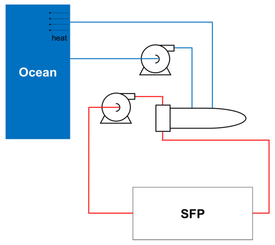
Figure 4.
Schematic of ocean-cooled indirect heat exchange system.
The evaluation summary of the system is shown in Table 13. This cooling system may be the most agreeable option to the regulatory body as the safety and the cooling performance of the system have been proven for the years of operating experience of the plant. For example, it has been shown that the sea water can provide sufficient heat sink for the spent nuclear fuels and the operating plant systems even under a hot temperature in a summer. In addition, the indirect heat exchange would effectively prevent potential radiation leakage to the environment. However, this may include a massive modification as much longer piping system is required routed from the sea to the heat exchanger in the fuel handling area. This also indicates that more secondary radioactive wastes can be produced from the decommissioning of the modified cooling system itself. Therefore, the cost for installation and clean-up would become much higher than other alternatives.
Table 13.
Evaluation summary of ocean-cooled indirect heat exchange system.
4.1.2. Air-Cooled, Indirect Heat Exchange
A brief configuration of an air/water indirect cooling system is shown in Figure 5. The cooling system consists of two closed loops; a primary cooling loop and a secondary cooling loop. Main components are a primary cooling pump, a heat exchanger, a secondary cooling pump, and an air-cooled chiller. The ambient air is used as the ultimate heat sink. The heat generated from the SFP is transferred to the heat exchanger through the primary cooling water. Then, the heat is transferred to the secondary cooling water through the heat exchanger. A plate type heat exchanger may be used to work with the modified secondary cooling loop components including the chiller. Finally, the heat is dissipated to the outdoor air through the chiller installed.
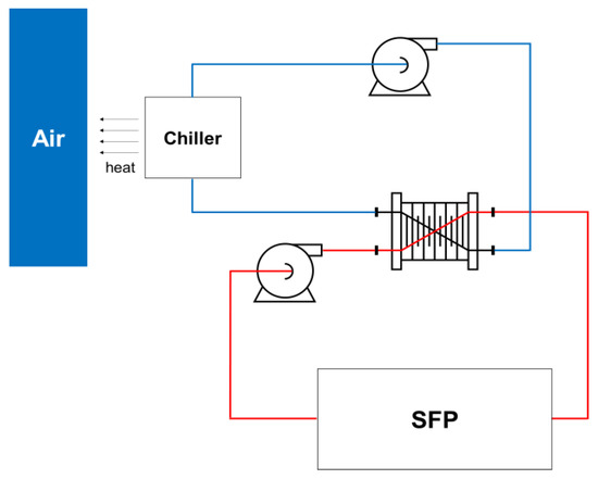
Figure 5.
Schematic of air-cooled indirect heat exchange system.
The evaluation summary of an air-cooled indirect system is shown in Table 14. Like the ocean-cooled system, the closed primary cooling loop can provide one more barrier for preventing potential radiation leakage to the environment. Also, the chiller can be installed near the fuel handling area or on the roof of the building. Hence, much less piping is required for the modification compared to the ocean-cooled system. This can reduce the cost and the secondary waste from decommissioning of the temporary SFP cooling system itself. Moreover, indirect air-cooled system is also a proven technology frequently adopted for the plant chiller systems.
Table 14.
Evaluation summary of ocean-cooled indirect heat exchange system.
4.1.3. Module, Direct Heat Exchange
A brief configuration of a modular cooling system is shown in Figure 6. The module type indicates that the components and the piping are combined in one modular system. There is single closed loop, and main components are a circulation pump, and an air-cooled chiller. The heat generated from the SFP is directly transferred to the chiller. Then, the heat is dissipated to the outdoor air. The modular system may be installed with a small modification of the current piping system as no heat exchanger is required.

Figure 6.
Schematic of a modular direct heat exchange system.
The evaluation summary of a module cooling system is shown in Table 15. It is the simplest design compared to other two alternatives. Moreover, this system is most commonly used in many industries, so finding suitable components and systems would be the easiest. Therefore, the cost is expected to be the lowest. However, this system may be more exposed to a potential risk of radiation leakage because no barrier from the system is expected due to the single cooling loop design. Therefore, the radiation shielding function has to be sufficiently convincing to the regulatory body to realize the system.
Table 15.
Evaluation summary of modular direct heat exchange system.
4.1.4. Selection of Cooling System
In this study, air-cooled indirect heat exchange system is selected for the temporary SFP cooling system. The first reason is that it has less potential radiation leakage to the environment compared to the module type. Potential radiation release to the environment can be greatly reduced because the closed secondary cooling loop can act as an additional barrier. This is also resulted in more favorable alternative for the regulation. Second reason is that the secondary radioactive waste produced would be much less than an ocean-cooled type. The chillers of the air-cooled system can be installed near the fuel handling area as long as they can contact to the outdoor air. The ocean-cooled system needs a long piping to the plant routed from the sea. Therefore, less secondary wastes are expected for the air-cooled types from the piping of the system. Moreover, the intake structure and other supporting systems need to be prepared for the ocean-cooled system. This would increase the cost, and may cause interference with decommissioning current intake structures and other supporting systems.
4.2. Applicable Configuration
An applicable configuration of the temporary SFP cooling system is developed for Kori units 3 and 4 as shown in Figure 7. The components of the primary cooling loop are remained almost as-is. The main reason is that the components are already designed to fully support sufficient radiation shielding function to store spent nuclear fuels in a normal operating condition. Also, the cooling capacity applied for the current SFPCCS is much higher than that of the temporary SFP cooling system. Hence, the SFP, primary cooling pumps, and piping of the current SFPCCS can be used without major modifications for the temporary SFP cooling system. On the other hand, major modifications of the system can be found on the secondary cooling loop. This is mostly due to the installation of the chillers. In addition, current piping connecting the CCWS and the NSCWS are disconnected to isolate the temporary SFP cooling system.

Figure 7.
Configuration of an applicable cooling system.
4.3. Primary Cooling Loop Components
The main components of the primary cooling loop are a spent fuel storage pool, two primary cooling pumps, and a heat exchanger. The spent fuel storage pool and cooling pumps of the current SFPCCS can be re-used and used for the temporary SFP cooling system. However, the heat exchanger may be replaced to a new component that will show a higher efficiency when working with the chillers installed on the secondary cooling loops.
The size of the replaced heat exchanger can be estimated through a calculation by using a number of transfer unit (NTU) method [20]. Operating parameters assumed for the calculation are mostly referring the operating data of the SONGS case. The assumed parameters are listed in Table 16 [21]. Hot side inlet temperature, 37.8 °C (100 °F), is reasonably lower than the system requirement which is to maintain the pool temperature less than 48.8 °C (120 °F).
Table 16.
Operating parameters assumed.
Now, the size of heat exchanger is estimated. The maximum possible heat transfer rate, qmax, can be calculated by Equation (4).
By substituting assumed values, the maximum possible heat transfer rate is obtained as 1.77(106) watts. The effectiveness, ε, can be calculated by Equation (5). The maximum heat load from the spent nuclear fuels of Kori units 3 and 4 was calculated as 1.66 (106) watts.
The effectiveness is obtained as 0.944. The heat capacity ratio, Cr, can be determined by Equation (6.)
The heat capacity ratio is obtained as 0.717. Now, the number of transfer unit, NTU, for the counter-flow heat exchangers with the Cr < 1 can be determined by Equation (7).
From the definition of NTU, the required surface area, A, of heat exchanger can be calculated by Equation (8).
Finally, U*A is obtained as 8.18(105) W/K. The U*A calculated for the current heat exchanger is 2.19 MBtu/h∙°F (1.15 MW/K) from the design calculation sheet of KHNP. This indicates that much smaller sized heat exchanger will be needed for the temporary SFP cooling system. Overall heat transfer coefficient, U, of a plate type heat exchanger is known as 1000~4000 W/m2∙K [20]. Therefore, required surface area would be between 205 and 818 square meters.
4.4. Secondary Cooling Loop Components
The main components of the secondary cooling loop are two cooling pumps and a group of chillers.
Required capacity of the chillers of the secondary cooling loop is approximated by using the chiller sizing formula. Equation (9) shows a calculation formula generally used in the industry [21].
The chilling system is often oversized by 20% to ensure sufficient capacity, so the ideal size of the chiller is obtained as 568.0 tons. The each rated capacity of the SONGS units 2 and 3 chillers is 198.90 tons to remove the heat load of 2.4 MBtu/h [22]. Hence, it can be verified that the calculated chiller size will be able to provide sufficient heat removal capacity for the temporary SFP cooling system.
The chillers are recommended to be installed on higher location than the heat exchanger to support a natural recirculation of the cooling water in the case of the forced circulation is not available. In addition, installing several chillers with smaller capacity are expected to ease burdens of operation and maintenance than operating a large chiller. For example, this would provide better operability in a case of contingency such as shutdown of one chiller due to a failure or scheduled maintenances. Furthermore, less heat removal capacity will be required in the future as the decay heat generated gradually decreases. Then, less number of chillers will be needed to maintain the pool temperature. In this case, the chillers no longer needed can be used for other nuclear power plants preparing decommissioning. Therefore, it is recommended to install multiple number of smaller chillers rather than one big chiller. To be more specific, four 150-ton chillers or three 200-ton chillers can be more preferred than one 600-ton chiller for Kori units 3 and 4. A survey of the major air-cooled chiller manufacturers supports this trend as shown in Table 17 [11]. Normally, cost of a chiller proportionally increases per the cooling capacity required. However, the unit price drastically increases if the chiller capacity is less than 150 tons due to the fixed costs for the manufacturing. Hence, each size of the chillers have to be greater than 150 tons to reduce the cost.
Table 17.
Average cost of industrial chillers.
4.5. Makeup Water
Makeup water is supplied from the demineralized water storage tanks. Hence, the current supply line from the condensate water storage tank is disconnected for the decommissioning activities. In some previous cases in the U.S., diverse makeup capability was used. For example, a high flow makeup pump, a low flow makeup pump, and an on-site hose were prepared [5]. Similar diverse makeup capability can also be used for the temporary SFP makeup system of Kori units 3 and 4.
4.6. Power
Current plant power systems for a normal operation will not be available to provide power for the pumps, chillers, and valves. Also, the temporary SFP cooling system is essentially isolated from the plant. Hence, off-site power sources should be utilized. Furthermore, a diesel generator shall be provided in case of a power failure. The nuclear power plants in Korea operate trailer-mounted mobile diesel generator as a back-up power of a power plant in normal operation. They will no longer be necessary when the plant is under decommissioning phase. In this case, the mobile diesel generator may be utilized as the emergency power supply for the temporary SFP cooling system.
5. Discussion
This study found that application of an independent temporary SFP cooling system can be a strong alternative for the preparation of the decommissioning of Kori units 3 and 4. The case study conducted found that there have been successful previous practices of other plants that had similar reactor types. This shows that the temporary SFP cooling system is technically achievable for Kori units 3 and 4. The installation cost per unit is estimated as 9.51 million U.S. dollars in year 2025, per unit through an analogous estimating technique. This shows that the costs for the temporary SFP cooling system are expected to be lower than using the dry casks.
The main system requirements of the temporary SFP cooling system are cooling capacity and plan for the potential single failure scenarios. To decide the cooling capacity of the system, maximum decay heat is estimated. Categorization of the spent nuclear fuels in the pool and decay heat calculation results obtained from ORIGEN are used in the estimating process. The result shows that 1.67 MW of the maximum decay heat of unit 4. In addition, two cases of single failures are considered; cooling pump failure and normal power failure. A redundant train and back-up diesel generator are provided as a response.
Then, applicable design of the temporary SFP cooling system is suggested. The primary cooling loop components are mostly used as-is. The components are already designed to support sufficient radiation safety and cooling function for a normal operation. By re-using the components, less secondary wastes will be produced, and greater economic benefit is expected. On the other hand, most components may be installed or replaced for the installation of the temporary SFP cooling system on the secondary cooling loop. This proposed design suggests four chillers of which each capacity is 150-ton.
Further studies may be performed for the system optimization, comprehensive safety analysis, and regulation systems in Korea regarding the application of the temporary SFP cooling system.
Author Contributions
Conceptualization, W.M. and C.-L.K.; methodology, W.M.; software, W.M. and C.-L.K.; validation, W.M. and C.-L.K.; investigation, W.M.; resources, W.M. and C.-L.K.; writing—original draft preparation, W.M.; writing—review and editing, W.M. and C.-L.K.; supervision, C.-L.K.; project administration, C.-L.K.; funding acquisition, C.-L.K. All authors have read and agreed to the published version of the manuscript.
Funding
This research was funded by Korea Institute of Energy Technology Evaluation and Planning and the Ministry of Trade, Industry & Energy (MOTIE), KETEP No. 20204010600130.
Conflicts of Interest
The authors declare no conflict of interest.
References
- Ministry of Trade, Industry and Energy (MOTIE). The Second Plan for High Level Radioactive Waste Management; Notice 2021-836; MOTIE: Sejong, Republic of Korea, 2021; pp. 16–17.
- Korea Hydro and Nuclear Power (KHNP). Final Safety Analysis Report for Kori units 3 and 4; KHNP: Gyeongju-si, Republic of Korea, 2006; Volume 9, pp. 9.1-6–9.1-12. [Google Scholar]
- Songa, M.; Kim, C.L.; Kessel, D.S. Consideration of Spent Fuel Pool Island as an Interim Management Option of Spent Nuclear Fuel for Kori unit 3&4 during Decommissioning of Kori site. Energy Strategy Rev. 2018, 21, 163–171. [Google Scholar]
- Jun, S.H. Feasibility Study of Applying the Spent Fuel Pool Island to Kori Units 3&4; KEPCO International Nuclear Graduate School: Ulsan, Republic of Korea, 2021; p. 51. [Google Scholar]
- Southern California Edison (SCE). San Onofre Nuclear Generating Station Units 2&3 Defueled Safety Analysis Report (DSAR), Rev.4; SCE: Rosemead, CA, USA, 2018; Volume 9, pp. 9-16–9-24. [Google Scholar]
- Wood, C. Maine Yankee Decommissioning—Experience Report, Electric Power Research Institute (EPRI) Technical Report; TR-1011734; EPRI: Washington, DC, USA, 2005; pp. 5-2–5-5. [Google Scholar]
- Lackey, M.B.; Fischer, J.P.; Rogan, F. Spent Fuel Pool Cooling and Cleanup during Decommissioning—Experience at Trojan Nuclear Power Plant, Electric Power Research Institute (EPRI) Technical Report; TR-112351; EPRI: Washington, DC, USA, 1999; pp. 2-2–3-6. [Google Scholar]
- Kenrich Group LLC (KRG). San Onofre Nuclear Generating Station units 2&3 2017 Decommissioning Cost Estimate, Rev.1; KRG: Washington, DC, USA, 2018; Appendix C; p. 1. [Google Scholar]
- National Aeronautics and Space Administration (NASA). NASA Cost Estimating Handbook; NASA CEH v.4.0; NASA: Washington, DC, USA, 2015; Appendix C; p. 15.
- EVC Valuation. The Cost-to-Capacity Method and Scale Factors. 2015. Available online: https://evcvaluation.com/the-cost-to-capacity-method-and-scale-factors/ (accessed on 1 October 2022).
- Florida Power & Light Company (FPL). Air-Cooled Chillers—An FPL Technical Primer. pp. 3–4. Available online: https://infpl.fpl.com/business/pdf/air-cooled-chillers-primer.pdf (accessed on 1 October 2022).
- Lee, J.S. Prediction on Korean Spent Nuclear Fuel Management. Nucl. Ind. 1992, 12, 26–33. [Google Scholar]
- Kim, G. Current status of nuclear fuel development. J. Electr. World 2000, 13, 16–23. [Google Scholar]
- Choi, H.-J.; Cho, D.; Kook, D.; Choi, J. Current status of spent fuels and the development of computer programs for the PWR spent fuel management in Korea. Nucl. Energy 2011, 53, 290–297. [Google Scholar] [CrossRef]
- Cho, D.K.; Kim, J.W.; Kim, I.Y.; Lee, J.Y. Investigation of PWR Spent Fuels for the Design of a Deep Geological Repository. J. Nucl. Fuel Cycle Waste Technol. 2019, 17, 339–346. [Google Scholar] [CrossRef]
- Dho, H.S.; Kim, T.M.; Cho, C.H. The Evaluation of Minimum Cooling Period for Loading of PWR Spent Nuclear Fuel of a Dual Purpose Metal Cask. J. Fuel Cycle Waste Technol. 2016, 14, 411–422. [Google Scholar] [CrossRef]
- NSSC. Provisions for Delivering Spent Nuclear Fuel; Korean Nuclear Safety and Security Committee (NSSC) Notice 2021-22§7; NSSC: Daejeon, Republic of Korea, 2021.
- Park, S.R. Design Class Study for Applying Spent Fuel Pool Island to Kori Units 3 and 4; KEPCO International Nuclear Graduate School: Ulsan, Republic of Korea, 2021; pp. 44–59. [Google Scholar]
- Korea Institute of Nuclear Safety (KINS). Regulation Guidance and Criteria for Pressurized Water Reactor; KINS/RS-N10.00; KINS: Daejeon, Republic of Korea, 2015; Chapter 10.
- Bergman, T.L.; Lavine, A.S.; Incropera, F.P.; Dewitt, D.P. Fundamentals of Heat and Mass Transfer, 7th ed.; John Wiley & Sons: Hoboken, NJ, USA, 2011; pp. 708–730. [Google Scholar]
- Cold Shot Chillers. Chiller Sizing Information; pp. 2–4. Available online: https://waterchillers.com/chiller-resources/sizing-information.html (accessed on 1 October 2022).
- Southern California Edison (SCE). Q&A about San Onofre Spent Fuel Pool Cooling Island Project. SCE Supplemental Information SFPI. 2015, pp. 10–13. Available online: https://sanonofresafety.files.wordpress.com/2011/11/sce-supplemental-information-sfpi-3-20-2015dgilmoreresponse.pdf (accessed on 1 October 2022).
Disclaimer/Publisher’s Note: The statements, opinions and data contained in all publications are solely those of the individual author(s) and contributor(s) and not of MDPI and/or the editor(s). MDPI and/or the editor(s) disclaim responsibility for any injury to people or property resulting from any ideas, methods, instructions or products referred to in the content. |
© 2023 by the authors. Licensee MDPI, Basel, Switzerland. This article is an open access article distributed under the terms and conditions of the Creative Commons Attribution (CC BY) license (https://creativecommons.org/licenses/by/4.0/).