1. Introduction
With the constant improvement in the urbanization level, the building sector has become a major consumer of global energy [
1]. In China, energy consumption in the building sector accounts for approximately 44.7% of the national total, and it is responsible for approximately 30% of the total CO
2 emissions [
2,
3]. The heating, ventilation, and air-conditioning (HVAC) systems based on mechanically driven vapor compression cooling technology consume approximately 65% of the overall building energy [
4]. The HVAC systems are being criticized not only because they consume a large amount of electrical energy but also because the refrigerants used contribute to ozone layer depletion and the greenhouse effect. As an alternative technology, absorption refrigeration systems (ARS) are receiving more and more attention for their ability to be activated by various low-grade heat sources, such as solar [
5,
6,
7], geothermal energy [
8,
9,
10], and waste heat [
11,
12,
13]. Moreover, the working pairs of the ARS can be environmentally friendly.
The most widely used absorbent–refrigerant pair in ARS for air-conditioning applications is LiBr-H
2O. To improve the system performance, researchers are still trying to seek better alternative working pairs [
14,
15]. Among them, LiCl-H
2O seems to be an efficient alternative working pair with the advantages of long-term stability, higher internal energy storage capacity, and relatively lower costs [
16,
17,
18]. In recent years, many studies have focused on the performance evaluation of LiCl-H
2O ARS. Parham et al. [
19] reported that the generation temperature of LiCl-H
2O ARS is lower than that for LiBr-H
2O ARS under the same condensation and absorption temperatures, and the LiCl-H
2O ARS has higher exergetic efficiency than the LiBr-H
2O ARS. Gunhan et al. [
20] conducted an experimental test and exergy analysis of a solar-assisted LiCl-H
2O ARS. The results showed that the exergetic efficiency of the whole system varied from 13.1% to 43.2% as the dead state temperature increased from 30 °C to 42 °C. Patel et al. [
21] compared the thermodynamic performance between LiCl-H
2O and LiBr-H
2O single-effect ARS. Results revealed that the COP and exergetic efficiency of LiCl-H
2O ARS were 4–9% and 3–6%, respectively, higher than that for LiBr-H
2O ARS. Bellos et al. [
22] examined the LiCl-H
2O and LiBr-H
2O working pairs in a solar absorption cooling system. They concluded that the LiCl-H
2O working pair performed better than the conventional LiBr-H
2O for all the examined cases, and the optimum heat source temperature for the LiCl-H
2O system was lower than that of the LiBr-H
2O system. Moreover, Gogoi et al. [
17] pointed out that LiCl-H
2O ARS was superior to LiBr-H
2O ARS under identical operating conditions. Ren et al. [
23] simply designed LiCl-H
2O and LiBr-H
2O water-cooled single-effect absorption chillers and found that the LiCl-H
2O ARS could be driven by a lower temperature of hot water compared to the LiBr-H
2O ARS, but its operating range was severely restricted by the solution crystallization.
The single-effect ARS is the most commonly studied, but it has relatively low COP and limitations on the utilization of high-temperature heat sources. The performance of ARS usually increases with the number of effects, but it leads to system complexity and investment cost increases. Moreover, the COP gain usually diminishes with the addition of every effect; thus, double-effect absorption refrigeration systems (DEARS) are preferred for commercial use in the refrigeration industry [
24,
25]. In recent years, a large number of studies on the performance analysis of DEARS have been reported. Farshi et al. [
24,
25,
26] examined the performance of three flow types of LiBr-H
2O DEARS (series, reverse, and reverse parallel) with various operating parameters. They demonstrated that the COPs and exergetic efficiencies of the parallel and reverse parallel systems were higher than those of the series system, while the parallel and reverse parallel configurations had wider operating ranges without crystallization risks of those of the series flow system. Bellos et al. [
18] examined the performance of a LiCl-H
2O DEARS with a parallel flow configuration powered by solar parabolic trough collectors. The results indicated that the solar cooling performance was 8% higher compared to operation with LiBr-H
2O. Konwar et al. [
27,
28] carried out detailed energy and exergy analyses of three configurations of LiCl-H
2O DEARS. They confirmed that LiCl-H
2O systems performed better than LiBr-H
2O systems, with higher COPs and exergetic efficiencies under the same operating conditions, particularly in low LPG and HPG temperature applications.
The conventional absorption systems using LiBr-H
2O as a working fluid suffer from a severe corrosion problem in the metal part of the machine at a high operating temperature, mainly occurring in the generator. To lower the heat source temperature while obtaining good performance, researchers have developed compression-assisted ARS by placing vapor compressors between system components. Dixit et al. [
29] proposed a compression-assisted LiBr-H
2O two-stage ARS and found that it performed better than the conventional system, with an optimized COP of 0.43 and exergetic efficiency of 11.68%. Bouaziz et al. [
30] proved that the LiBr-H
2O double-stage ARS with a vapor compressor could operate at a lower temperature of approximately 60–120 °C, instead of 100–160 °C for the conventional cycle. Shu et al. [
31] investigated a compressor-assisted triple-effect LiBr-H
2O absorption cooling cycle coupled with a Rankine cycle. They concluded that the maximum generation temperature was 50 °C lower than that of the traditional triple-effect ARS. Recently, many researchers have extended the compressor-assisted ARS for various alternative working pairs. Ventas et al. [
32] studied a single-effect NH
3-LiNO
3 ARS integrated with a compressor between the evaporator and absorber. They pointed out that this cycle could work at lower driving temperatures than the single-effect ARS, and the capacity rose with the increase in the compressor pressure ratio at the same driving temperature. Sun et al. [
33] analyzed the thermodynamic performance of single-effect compression-assisted absorption refrigeration cycles using R1234yf/ionic liquid as working fluids. They concluded that the compression-assisted cycle could effectively improve the cooling performance, reduce the circulation ratio, and extend the operation ranges compared to the single-effect ARS. Wu et al. [
34] pointed out that the compression-assisted absorption cycle with an auxiliary compressor positioned between the evaporator and absorber performed better than that between the generator and condenser due to the higher cycle efficiency and lower compressor discharge temperature.
The previous studies indicate that the LiCl-H2O working pair performs better than the conventional LiBr-H2O working pair in the ARS. However, the operating range of the LiCl-H2O ARS is strictly restricted compared to LiBr-H2O ARS. According to the aforementioned research, the parallel and reverse parallel flow arrangements are superior in performance, with lower crystallization probabilities and higher COPs, suggesting that the distribution ratio plays an important role in determining the performance of the DEARS. Moreover, the compressor-assisted ARS proves to be an efficient means to improve the system performance and lower the temperatures of heat sources. Most of the previous studies in this field have focused on the LiBr-H2O working pair, and there is still a lack of knowledge on the LiCl-H2O working pair applied in the compression-assisted DEARS. Considering the research gap, the most important contribution of the study is to propose the compression-assisted DEARS arranged in series parallel and reverse parallel configurations for the application of LiBr-H2O and LiCl-H2O working pairs. In these two configurations, solution distributors are used to lower the concentrations of strong solutions for wider operating ranges, and the vapor compressors are designed for low-temperature heat source utilization and higher system performance. The innovation of this work lies in the performance comparison of the two configurations with these working fluids. Moreover, the effect of the operating conditions on the solution crystallization risk is considered and the salt concentrations of these working fluids are presented. The main objectives of this work can be summarized as follows:
- (1)
Proposal of two novel arrangements of compression-assisted DEARS using LiBr-H2O and LiCl-H2O as working pairs;
- (2)
Development of mathematical models to evaluate the system performance from a thermodynamic viewpoint;
- (3)
Examination of the effects of the compression ratio and distribution ratio on the COP and exergetic efficiency.
2. System Description and Crystallization Conditions
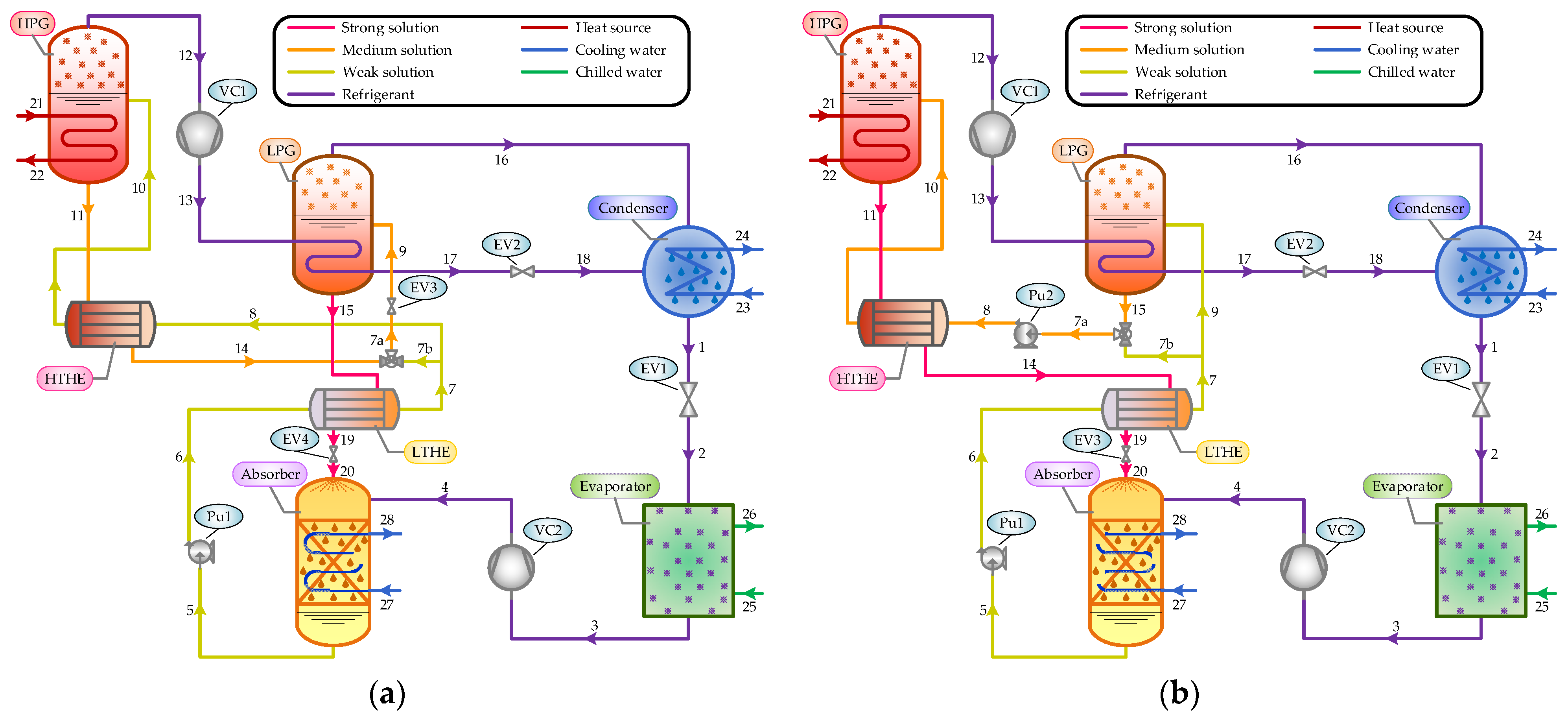
The schematic diagram of the proposed system is depicted in
Figure 1. The main components of the compressor-assisted DEARS are a high-pressure generator (HPG), low-pressure generator (LPG), absorber (abs), condenser (con), evaporator (eva), high-temperature heat exchanger (HTHE), low-temperature heat exchanger (LTHE), solution pump (Pu), expansion valve (EV), and vapor compressor (VC).
In the system operation, the weak solution (stream 10) is pumped to the HPG, where it is heated by the heat source to separate the refrigerant vapor from the solution at a high pressure and temperature. Then, the primary refrigerant vapor (stream 12) is compressed by VC1 and flows into the LPG, where it (stream 13) is condensed into a saturated liquid by transferring heat to the weak solution (stream 9). At the outlet of the LPG, the secondary vapor (stream 16) produced from the weak solution, together with the condensed water (stream 18), flows into the condenser and cools down to a saturated liquid. After this, the liquid refrigerant (stream 1) enters the evaporator through an expansion valve (EV1), where it absorbs heat at a low pressure to produce a cooling capacity. The refrigerant vapor (stream 3) leaving the evaporator is compressed by VC2 and flows into the absorber to be absorbed by the strong solution (stream 20).
The path described above is the same for the two systems considered in this study. In both the SP and RP configurations, the weak solution (stream 5) leaving the absorber is divided into two streams after passing through the LTHE.
Figure 1a shows the schematic diagram of the SP configuration. As can be seen, one part of the weak solution (stream 8) passes to the HPG via the HTHE to generate a primary vapor, and the other part (stream 7b) is mixed with the medium-concentration solution (stream 14) exiting the HPG before it is routed to the LPG through EV3. The strong solution leaving the LPG (stream 15) flows back to the absorber through the LTHE and EV4 successively. In the RP configuration shown in
Figure 1b, the main part of the weak solution (stream 9) passes to the LPG for refrigerant vapor generation, where the medium-concentration solution (stream 15) is produced. The other part of the weak solution (stream 7b) is mixed with the medium-concentration solution exiting the LPG and pumped to the HPG via the HTHE. The strong solution (stream 11) flows through the two solution heat exchangers (HTHE and LTHE) and an expansion valve (EV3) before it finally enters the absorber.
In the SP and RP systems, a shell and tube heat exchanger structure can be used for the generator, absorber, evaporator, and condenser. The generator and absorber are considered to be falling film vertical tube heat exchangers. The condenser and evaporator are regarded as horizontal tube heat exchangers. The double-pipe heat exchanger is applied in the solution heat exchanger. Different types of vapor compressors, such as Roots or vortex blowers, can be chosen according to the pressure and temperature of the refrigerant.
Figure 2 presents the
P-
T-
x diagram of the two compression-assisted systems. When the solution concentration increases or the solution temperature decreases, crystallization is most likely to take place, interrupting machine operation. The greatest probability of crystal formation in the two systems is located between the LTHE and absorber because this is the point of highest concentration and lowest temperature. In this work, the crystallization conditions can be determined using the solubility boundary curve of the LiCl-H
2O and LiBr-H
2O solutions in Refs. [
12,
35], so the operating range of each system is obtained in which crystallization does not occur.
5. Results and Discussion
In this section, the simulation results are presented and discussed. The series parallel and reverse parallel systems are examined separately to analyze the effects of the distribution ratio (D) and compression ratio (CR) on system performance. All the cases are simulated at tabs = tcon = 35 °C and teva = 5 °C.
5.1. Effect of Distribution Ratio (D) on the Performance of DEARS
Figure 3a,b illustrate the variations in the COP and exergetic efficiency at different distribution ratio levels (0–0.2–0.4) for the SP and RP systems. As can be seen, for the two configurations, the LiCl-H
2O systems perform better than the LiBr-H
2O systems for all the examined cases in terms of the COP and exergetic efficiency under identical operating conditions, particularly at the low
tHPG. Compared with the LiBr-H
2O systems, the LiCl-H
2O systems have narrow operating ranges due to the crystallization of strong solutions. As the
tHPG rises, the COP for each LiBr-H
2O SP or RP system initially exhibits a significant increase and then levels off, while the exergetic efficiency reaches its maximum value and decreases thereafter. Better performance can be obtained at the condition that D = 0.4 for the SP system, in contrast to D = 0 for the RP system. For the LiBr-H
2O DEARS, the maximum COPs are approximately 1.304 and 1.299, respectively, for the SP and RP systems, and the maximum exergetic efficiencies occur at the value of
tHPG approximately 135 °C, being close to 0.2206 and 0.2213 for the SP and RP systems, respectively.
This can be explained by the following facts. In the SP system, the mass flow rate of the weak solution entering the HPG decreases with the increase in the distribution ratio, resulting in a reduction in the HPG heat load. In consequence, the COP increases under the constant cooling capacity. Differently, in the RP system, the mass flow rate of the medium-concentration solution pumped to the HPG increases as the distribution ratio rises, which eventually leads to an increase in the HPG heat load; thus, the COP declines slightly. However, in both the SP and RP systems, the exergetic efficiencies decline at the higher tHPG, which is attributed to the enhancement in the quality of heat energy input to the HPG.
Another indication in
Figure 3 is that a higher distribution ratio is beneficial to the system operating range, which allows for the utilization of heat sources with higher temperatures. Compared to the systems without solution distributors, the increases in operating ranges are approximately 10 °C for the LiBr-H
2O systems and 5 °C for the LiCl-H
2O systems at D = 0.4. The reason is that the concentration of the medium solution becomes lower upon mixing with the weak solution, leading to a decrease in the concentration of the strong solution flowing out of the HPG (for the RP system) or LPG (for the SP system), as proven in
Figure 4. It can be seen from
Figure 4a,b that, at a certain
tHPG, the concentration difference in the outlet solutions between the HPG (
x11) and LPG (
x15) becomes smaller as the distribution ratio rises, which means that a system with a high distribution ratio can utilize higher-temperature heat sources without solution crystallization.
For the LiBr-H2O working pair, when the SP and RP systems operate at tHPG = 145 °C, the concentrations of the strong solutions flowing to the absorber are estimated to be 63.66%, 62.92%, and 61.90%, respectively, for the SP system, as well as 64.28%, 63.60%, and 62.63%, respectively, for the RP system, corresponding to the three different distribution ratio levels (0–0.2–0.4). Moreover, the LiCl-H2O working pair has narrow operating ranges for both the SP and RP systems due to the limitation of salt solubility. In the examined cases, the maximum concentrations of the LiCl-H2O strong solutions are 48.12% and 48.39%, respectively, for the SP and RP systems.
5.2. Effect of Compression Ratio of VC1 on the Performance of DEARS
Figure 5 and
Figure 6 depict the variations in the COP and exergetic efficiency with
tHPG at different CR
1 levels (1–1.5–2) for the SP and RP systems. It can be seen that the system performance at a low value of
tHPG under 120 °C is improved substantially with the help of VC1. Moreover, for all the cases, the operating ranges are enlarged at a higher distribution ratio. The reason is that the pressure of the HPG reduces with the increase in CR
1, leading to an enhancement in the generation process and an increase in the solution concentration in the HPG at the low
tHPG, as shown in
Figure 7 and
Figure 8. As a consequence, the deflation ratio of the HPG rises, which causes the mass flow rate of the solution to decrease, and, eventually, the heat load of the HPG declines. The COPs of the LiBr-H
2O and LiCl-H
2O systems increase because the reduction in the heat loads in the HPG is greater than the power consumed by VC1. The exergetic efficiencies of the LiBr-H
2O systems increase initially to reach their maximum values and thereafter decrease. For the LiBr-H
2O SP and RP systems, the values of
tHPG corresponding to the maximum exergetic efficiencies in the case of CR
1 = 1, 1.5, 2 are 135 °C, 120 °C, and 110 °C, respectively.
Figure 7 and
Figure 8 present the variations in solution concentrations with
at different CR
1 levels for the SP and RP systems, respectively. As can be seen, the concentrations of the solutions exiting the HPG and LPG rise obviously at a relatively low
tHPG. At the condition that
tHPG =120 °C and D = 0, the concentrations of the strong solutions are approximately 56.95%, 60.06%, and 62.30%, respectively, for the SP system, as well as 57.0%, 60.33%, and 62.62%, respectively, for the RP system, corresponding to the three different CR
1 levels (1–1.5–2). Meanwhile, as the
tHPG rises, the concentrations of the strong solutions in the SP and RP systems with D = 0.4 increase more slowly than those in the systems without solution distributors, which indicates that the system can operate at a higher
tHPG under the restriction of solution crystallization.
5.3. Effect of the Compression Ratio of VC2 on the Performance of DEARS
The variations in the COP and exergetic efficiency with
tHPG at different CR
2 levels (1–1.5–2) for the SP and RP systems are illustrated in
Figure 9 and
Figure 10. It is observed that the use of VC2 can greatly improve the system performance and operating ranges, especially for the LiCl-H
2O working pair. It can be seen that the operating temperature of the HPG in the LiCl-H
2O SP system ranges from 90 °C to 125 °C when the CR
2 = 2 and D = 0.4, compared with that from 115 °C to 125 °C when the CR
2 = 1 and D = 0.4. Moreover, the operating ranges of all the systems can be expanded clearly at a higher distribution ratio under the same value of CR
2. In particular, as
Figure 9 and
Figure 10 demonstrate, at a higher CR
2 greater than 2, the system can be driven by the low-temperature heat source under 100 °C, while the COP and exergetic efficiency remain at high levels in this condition. Moreover, the maximum values of the COP and exergetic efficiency for each system increase with the CR
2 in the operating range. In all the examined cases, the maximum COPs are 1.389 and 1.415, respectively, for the LiBr-H
2O and LiCl-H
2O systems with the SP configuration at CR
2 = 2 and D = 0, while the maximum exergetic efficiencies are 0.2454 and 0.2569, respectively. The corresponding maximum COP and exergetic efficiency are obtained at
tHPG = 115 °C and
tHPG = 100 °C, respectively, for the LiBr-H
2O system, as well as
tHPG = 110 °C and
tHPG = 95 °C, respectively, for the LiCl-H
2O system.
This can be explained by the following facts. For each system, the pressure of the absorber rises with the increase in CR2, which enhances the absorption process in the absorber; thus, the concentration of the weak solution leaving the absorber becomes lower at a fixed absorption temperature. In this instance, the solution concentration differences between the inlet and outlet of both the HPG and LPG are augmented, resulting in the mass flow rates of the solutions in the HPG and LPG decreasing, as well as their heat loads. Consequently, the COP increases with the increase in CR2 under the same operating temperatures because the effect of HPG heat load reduction is dominant over the electric power consumed by VC2.
The variations in the solution concentrations with
at different CR
2 levels for the SP and RP systems are shown in
Figure 11 and
Figure 12, respectively. It is obvious that, as the CR
2 rises, the concentrations of the medium solutions for the SP system (
x11) and RP system (
x15) decrease, while the concentrations of the strong solutions for the SP system (
x15) and RP system (
x11) increase at the same
tHPG. The gap between the concentrations of the medium and strong solutions is narrowed considerably with the increase in the distribution ratio. Furthermore, the SP and RP systems with a higher CR
2 could operate at lower solution concentrations compared to the conventional systems without vapor compressors when the
tHPG becomes lower. In the operating ranges of the SP system with D = 0.4, the concentrations of the strong solutions range from 49.37% to 65.44% and from 35.83% to 47.79%, respectively, for the LiBr-H
2O and LiCl-H
2O working pairs at CR
2 = 2, while they range from 55.42% to 64.89% and from 42.90% to 47.95%, respectively, at CR
2 = 1.
Compared to the SP and RP systems with VC1, the systems adopting VC2 exhibit lower concentrations of the strong solutions at the same HPG temperature and compression ratio. In the condition that tHPG = 110 °C and D = 0.4, the concentrations of the strong solutions are approximately 54.68% and 55.09%, respectively, for the SP and RP systems at CR2 = 2, compared with that of 58.49% and 58.83%, respectively, at CR1 = 2. Therefore, the operating ranges of the SP and RP systems become wider with the help of VC2 because the lower concentrations of the weak and strong solutions are suitable for low-temperature heat source utilization.
5.4. Effect of CR1 and CR2 on the Performance of DEARS
In this section, a set of specific operating conditions are chosen to investigate the effect of CR
1 and CR
2 on the system performance at D = 0.4. To cover a great range of operating conditions, the system performance is analyzed for three different CR
1 levels (1–1.5–2), while the CR
2 ranges from 1 to 2. The obtained results for the LiBr-H
2O and LiCl-H
2O SP systems are shown in
Figure 13 and
Figure 14. It can be seen that the proposed systems with higher CR
1 and CR
2 have a great advantage in operating at low
tHPG. In the condition that CR
1 and CR
2 are equal to 2, the LiBr-H
2O and LiCl-H
2O SP systems can operate at
tHPG =75 °C with high COPs and exergetic efficiencies of approximately 1.183 and 0.2330, respectively, for the LiBr-H
2O working pair, as well as 1.310 and 0.2504, respectively, for the LiCl-H
2O working pair. This fact means that the proposed systems can be driven by low-temperature heat sources below 100 °C at relatively higher values of CR
1 and CR
2 with satisfactory performance.
It can be seen from
Figure 13 that, at a constant CR
1, the COP for each LiBr-H
2O and LiCl-H
2O SP system rises with the increase in CR
2 under the same operating temperatures, while the exergetic efficiency reaches its maximum value with the variation in
tHPG, as shown in
Figure 14. At a constant CR
2, the maximum values of the COP and exergetic efficiency decrease slightly for the systems as CR
1 increases. The maximum COPs for the LiBr-H
2O SP systems are obtained at CR
2 = 2, which are close to 1.389, 1.86, and 1.384, respectively, for the three incremental CR
1 levels, corresponding to the
tHPG of 115 °C, 100 °C, and 95 °C, respectively. Similarly, the maximum COPs for the LiCl-H
2O SP systems reach 1.415, 1.405, and 1.398, respectively, for these three CR
1 levels, corresponding to the
tHPG of 110 °C, 95 °C, and 90 °C, respectively. It is clear that the optimum system performance can be achieved by adjusting the values of CR
1 and CR
2 according to the heat source temperature.
Figure 15 and
Figure 16 present the effects of CR
1 and CR
2 on the COP and exergetic efficiency for the LiBr-H
2O and LiCl-H
2O RP systems. It is apparent that, as CR
1 and CR
2 increase, the LiBr-H
2O and LiCl-H
2O RP systems exhibit better performance at lower values of
tHPG. The LiBr-H
2O and LiCl-H
2O RP systems can operate at a low
tHPG of approximately 75 °C with COPs of 1.164 and 1.295, respectively, and the exergetic efficiencies of 0.2310 and 0.2489, respectively, when CR
1 and CR
2 are equal to 2. This means that the compression-assisted systems could utilize low-temperature heat energy efficiently, and the LiCl-H
2O working pair is more suitable than the LiBr-H
2O working pair in this situation due to the higher COP and exergetic efficiency. As the
tHPG rises, the COP for each RP system increases sharply at first and then maintains a certain level, while the exergetic efficiency increases initially to reach its peak and then declines rapidly. For almost all the cases, the maximum COP and exergetic efficiency could be obtained at the condition that CR
2 = 2, and they are calculated to be 1.371 and 0.2420, respectively, for the LiBr-H
2O RP systems, as well as 1.40 and 0.2515, respectively, for the LiCl-H
2O RP systems.
6. Conclusions
In this study, new series parallel and reverse parallel configurations for compression-assisted DEARS are investigated. Performance comparisons between the LiCl-H2O and LiBr-H2O working pairs are conducted under various values of the compression ratio (CR) and distribution ratio (D) considering the crystallization problem. The main conclusions are drawn as follows.
(1) The SP and RP systems with higher distribution ratios are conducive to extending the operation ranges and utilizing the heat energy with higher temperatures. As the distribution ratio rises, the COP and exergetic efficiency increase slightly in the SP system, but decrease in the RP system. In the comparison of the two configurations, the series parallel flow has an advantage in the operating range, but the reverse parallel flow shows a slightly higher COP and exergetic efficiency.
(2) The compression-assisted systems improve the performance substantially at lower HPG temperature conditions, which means that low-temperature heat energy could be utilized efficiently. The compressor placed between the evaporator and absorber is more effective than that between the HPG and LPG in the aspect of lowering the heat source temperature and improving system performance.
(3) In all the examined cases, LiCl-H2O is the working pair with better performance in terms of COP and exergetic efficiency, especially in low-temperature heat source utilization. The operating range of the LiCl-H2O system is extended obviously at a higher CR2 with a distribution ratio of 0.4, which is feasible for the LiCl-H2O working pair in practical application.
(4) The proposed system at relatively higher CR1 and CR2 values could utilize low-temperature heat sources below 100 °C with satisfactory performance. In the condition that the CR1 and CR2 are equal to 2, the LiBr-H2O and LiCl-H2O systems could operate at a low tHPG of approximately 75 °C with high levels of COP and exergetic efficiency above 1.16 and 0.231, respectively, for the LiBr-H2O working pair, as well as 1.29 and 0.248, respectively, for the LiCl-H2O working pair.
(5) At a certain value of CR1, the maximum values of the COP and exergetic efficiency for the LiBr-H2O and LiCl-H2O systems rise with the increase in CR2. For all the examined cases, the maximum values of the COP and exergetic efficiency occur in the SP configuration at CR2 = 2 and D = 0.4, which are 1.389 and 0.2454, respectively, for the LiBr-H2O working pair, as well as 1.415 and 0.2569, respectively, for the LiCl-H2O working pair.


