

Structural Performance-Based Design Optimisation of a Secondary Mirror for a Concentrated Solar Power (CSP) Plant
 ,
, 
 ,
,
Abstract
:1. Introduction
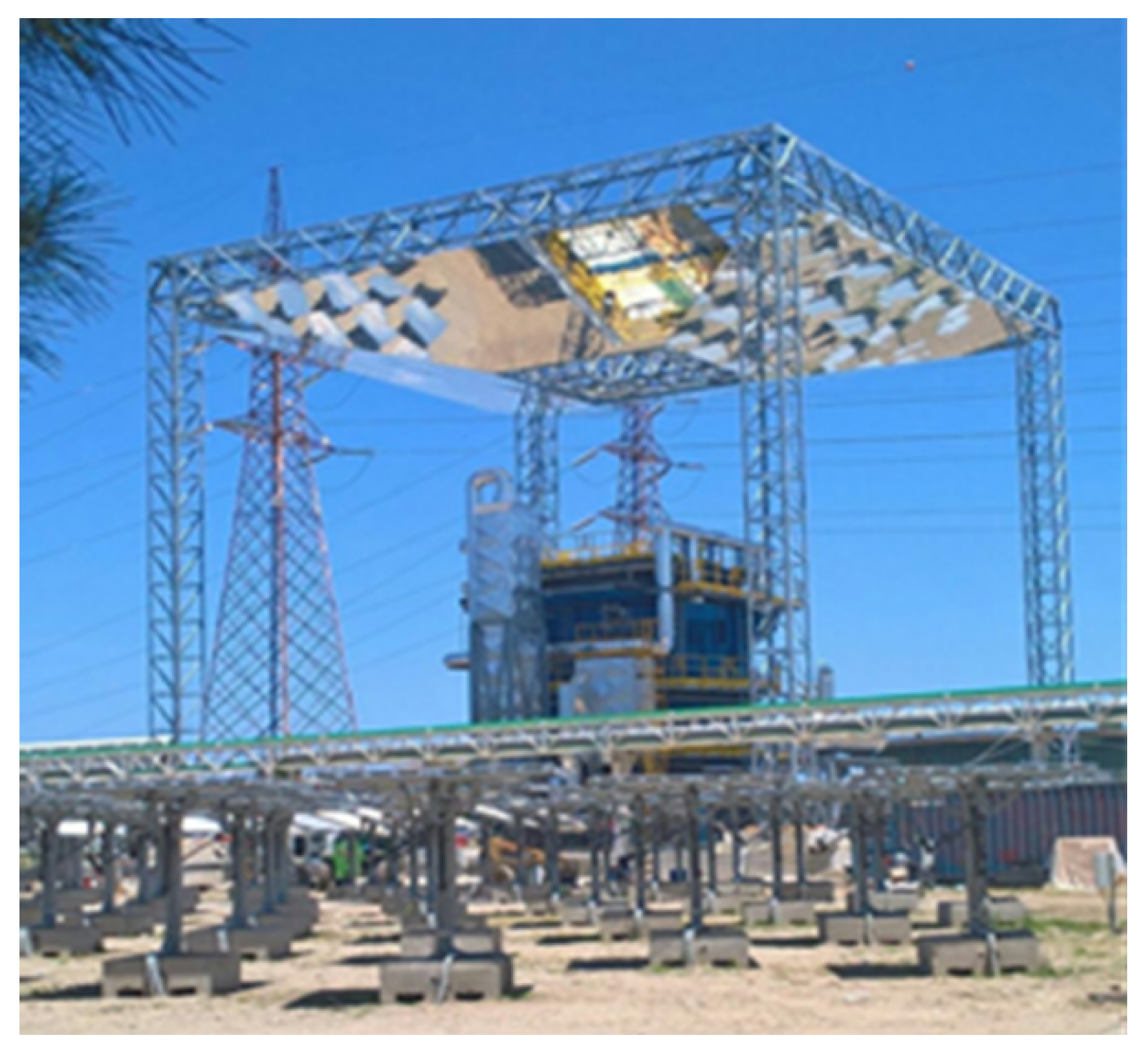
1.1. Magaldi STEM® Description
- One heliostat field with motorised mirrors tracking the sun’s position.
- A beam-down tower with secondary mirrors.
- A fluidised bed solar receiver with an integrated thermal energy storage (TES) system constituted of silica sand, which is stable to temperatures beyond 1000 °C, enabling energy storage as sensible heat with large energy density.
- A fluidising gas supply system, including air distribution manifolds, blower, air preheater, filter unit, and induced draft fan.
- A feedwater/steam circuit, including once-through in-bed heat exchangers, condenser, deaerator, and feeding pump, to produce dispatchable heat and/or electricity.
- Control systems for heliostat sun tracking and fluidised bed receiver operations.
1.2. Beam-Down Mirror DESIGN and Optimisation
2. Methodology
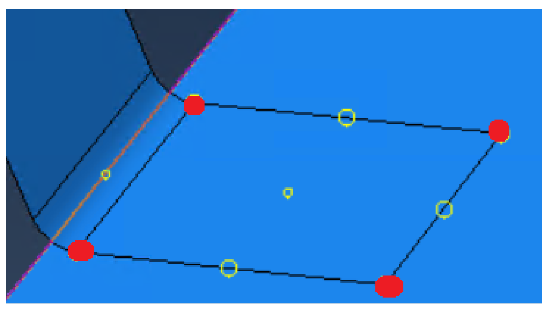
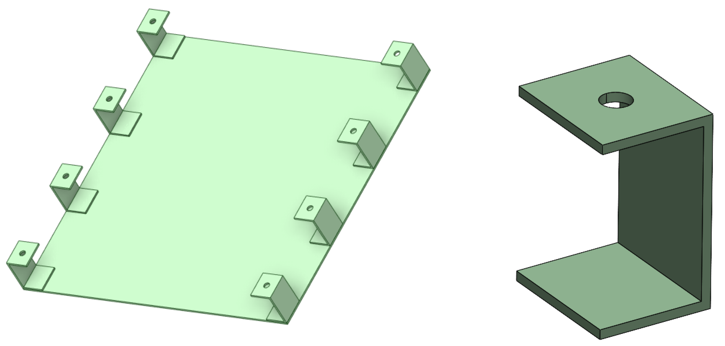
2.1. Base Design
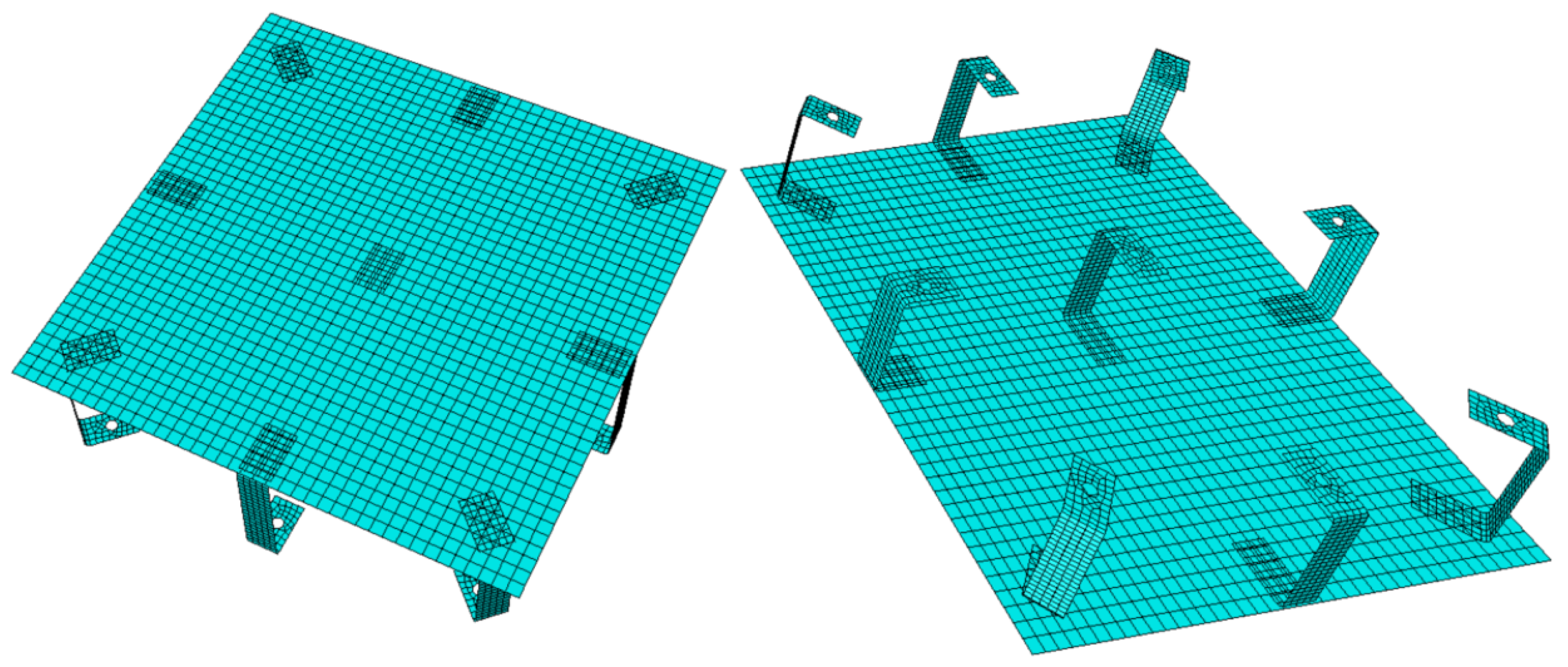
2.2. Developed Structural Model
- If , the highlighted brackets are excluded from the configuration.
- If , the highlighted central bracket is included in the configuration.
- If , only the highlighted central bracket is excluded from the configuration.
- If , all the brackets are included in the configuration.
- The thermal load is applied by imposing a homogeneous temperature of 200 °C to both plate and brackets.
- The wind load is applied as the drag and lift pressures acting on the plate surface in two different wind conditions:
- –
- Mean wind, with a speed of 13 km/h.
- –
- Maximum wind, with a speed of 30 m/s.
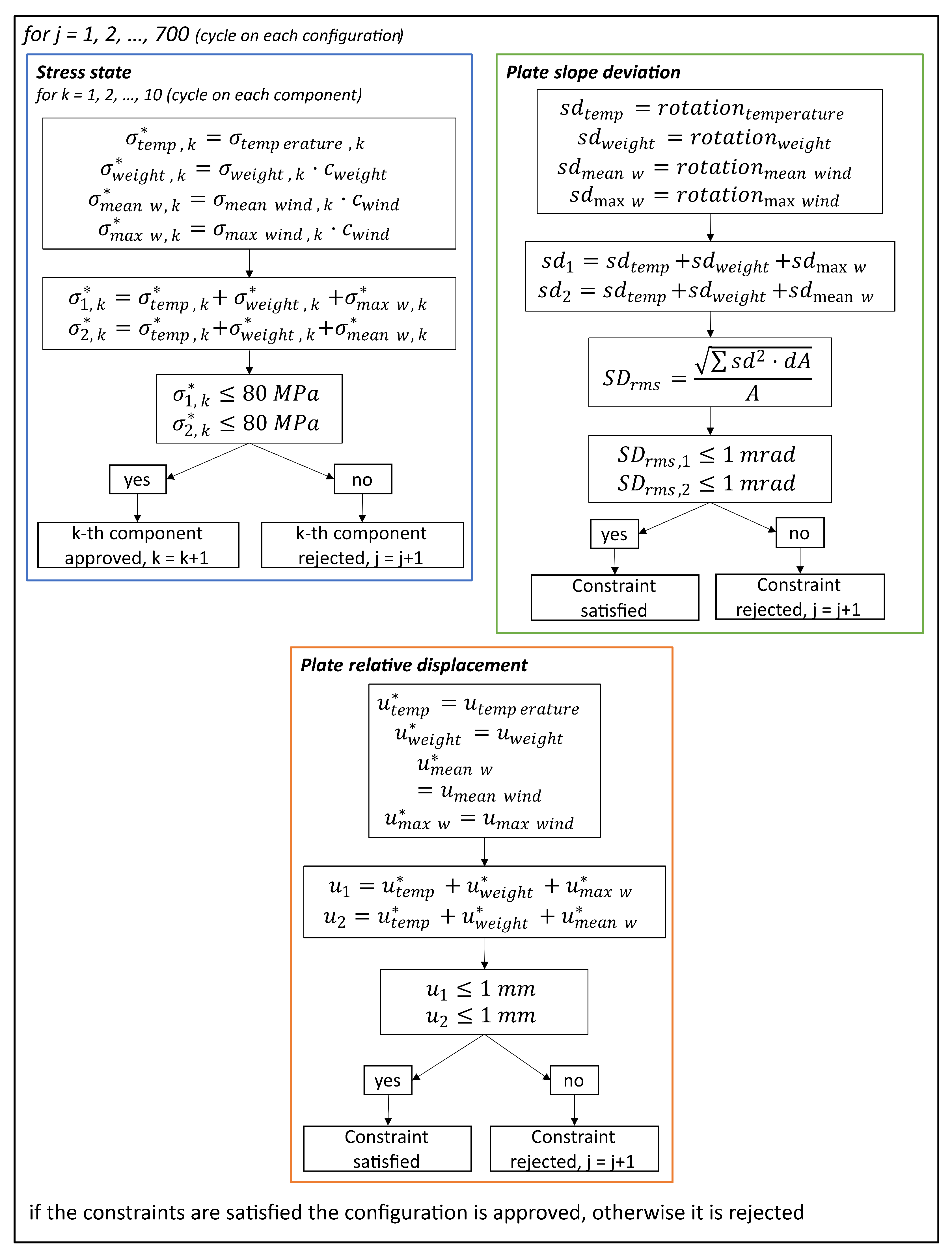
2.3. Algorithm
Optimisation Algorithm
- Design variables: These are the quantities whose values are modified in the optimisation process to determine the optimal solution to the problem. These variables can be discrete or vary within a continuous range of values.
- Objective function: The objective function is the function that the optimiser aims to minimise (or maximise). It depends on the values of the design variables. In the case where more than one objective function is considered within the optimisation process, it is referred to as multi-objective optimisation.
- Constraints: Constraints represent conditions that limit the search space for the optimal solution. They are expressed in the form of equations and/or inequalities, generally as a function of constant parameters, design variables, and/or the objective function.
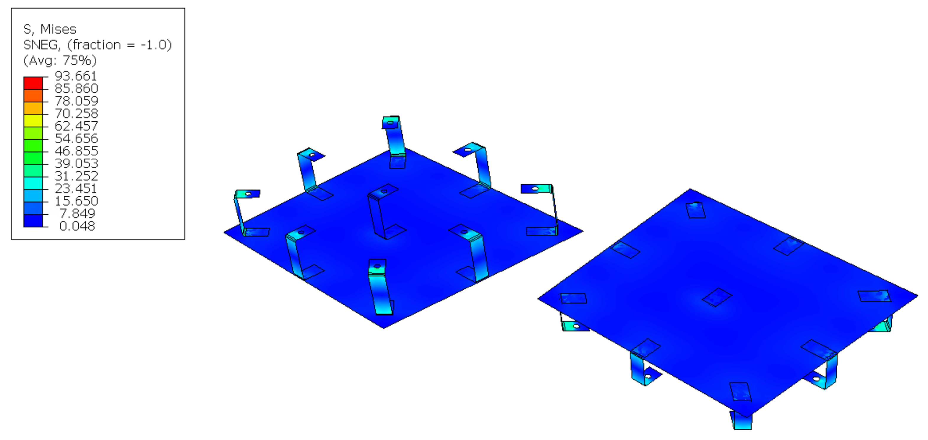
- The amplification of the stress state is carried out according to the coefficients defined in Eurocode 3 [19], specifically for the stresses caused by the weight force and for those due to wind action.
- Sum of the stress state obtained in the different loading conditions for all the components. Given the two conditions for the wind, two different summation terms will be obtained, one for the medium wind condition and one for the maximum wind condition.
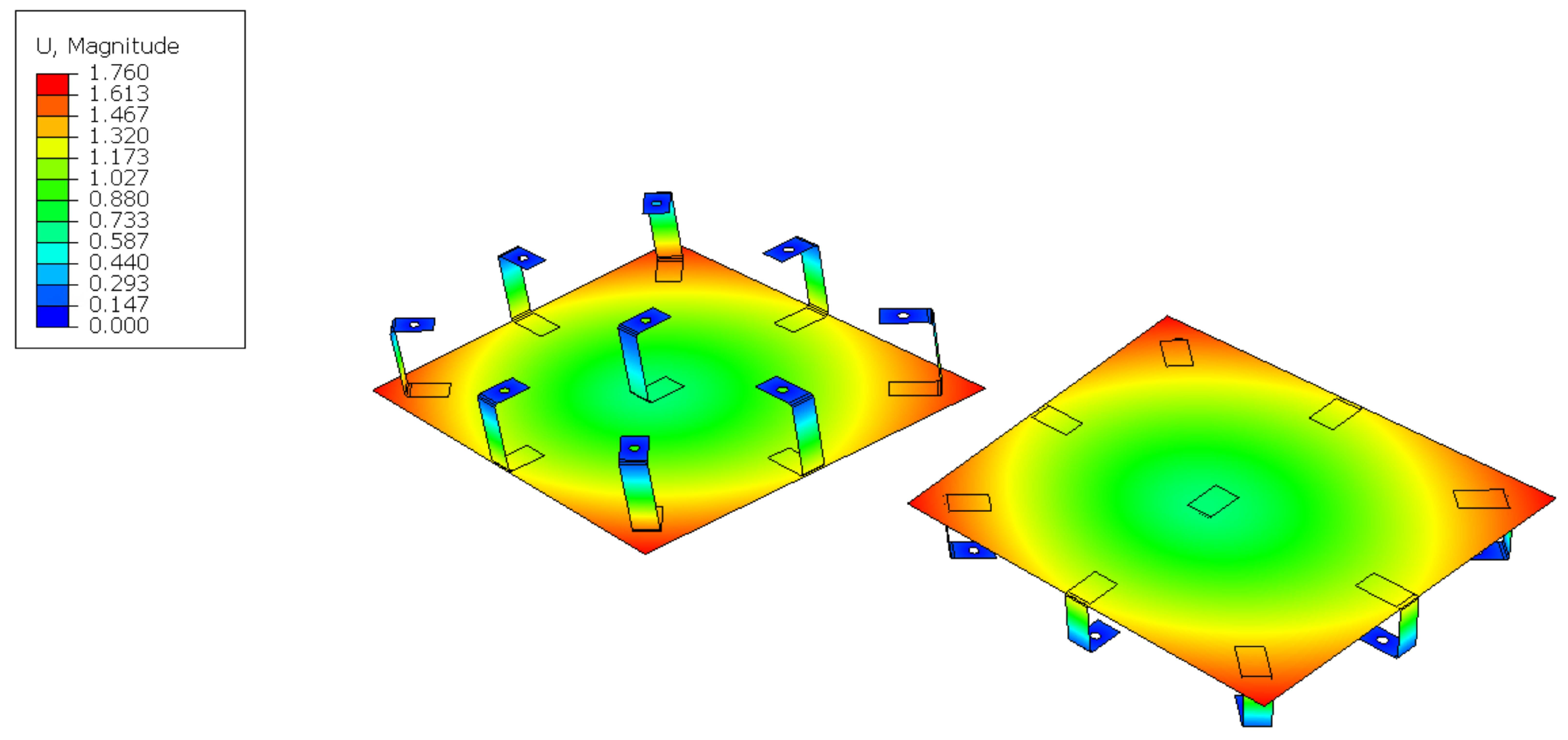
- Sum of plate displacements under the different loads. Given the two conditions for the wind, two different summation terms will be obtained, one for the medium wind condition and one for the maximum wind condition.
- For each configuration, check that
- –
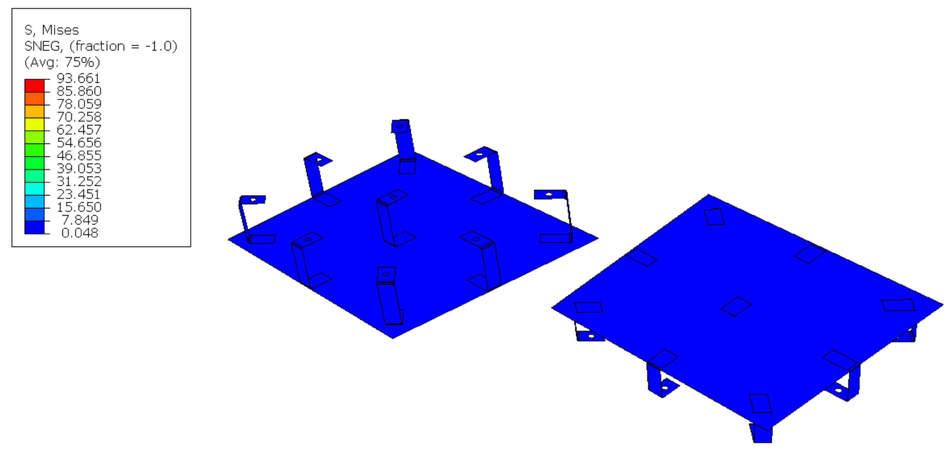
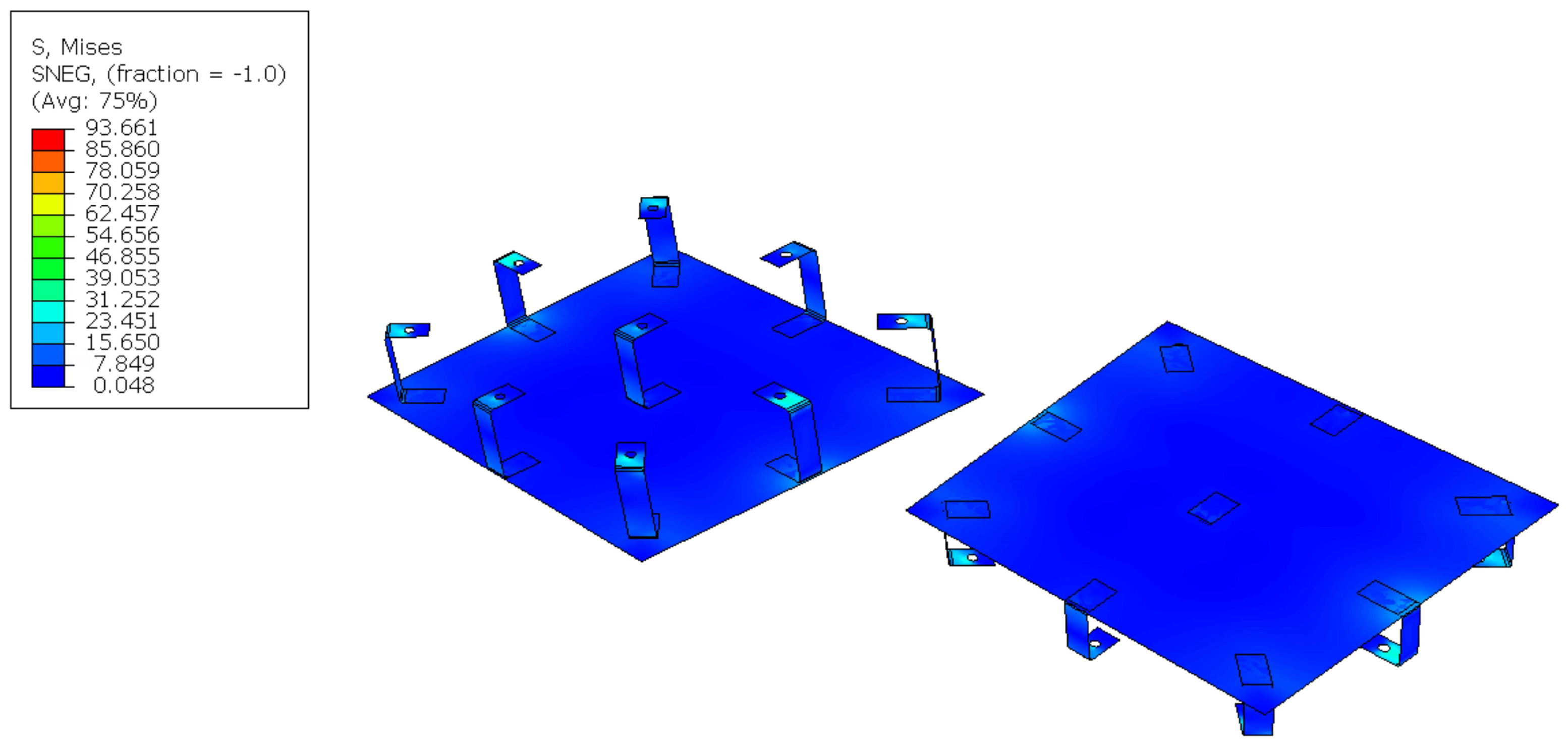
- Maximum stress MPa for each component. This constraint is used to minimise fatigue damage to the components since the wind and the temperature are cyclic loads and, at the same time, to avoid welding.
- –
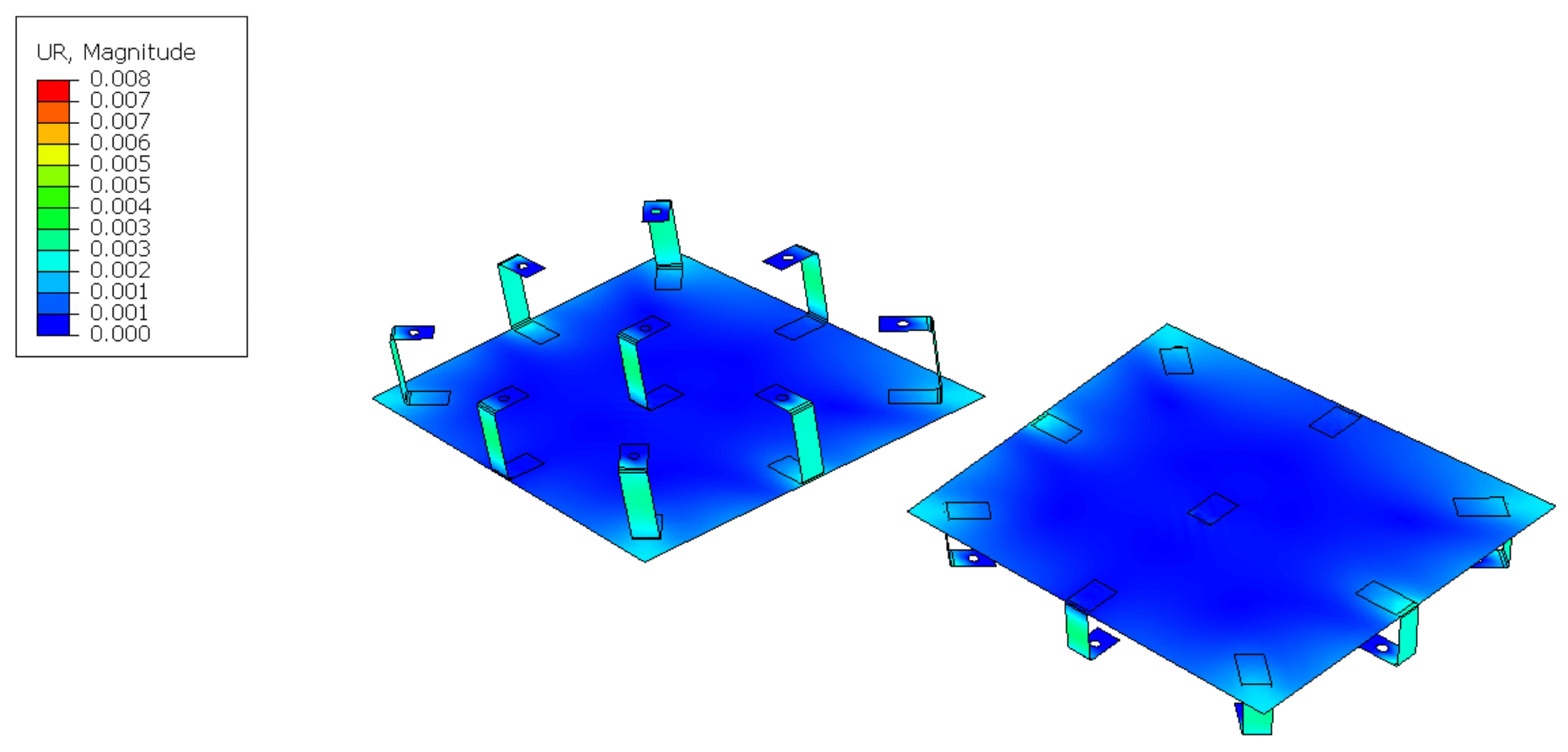
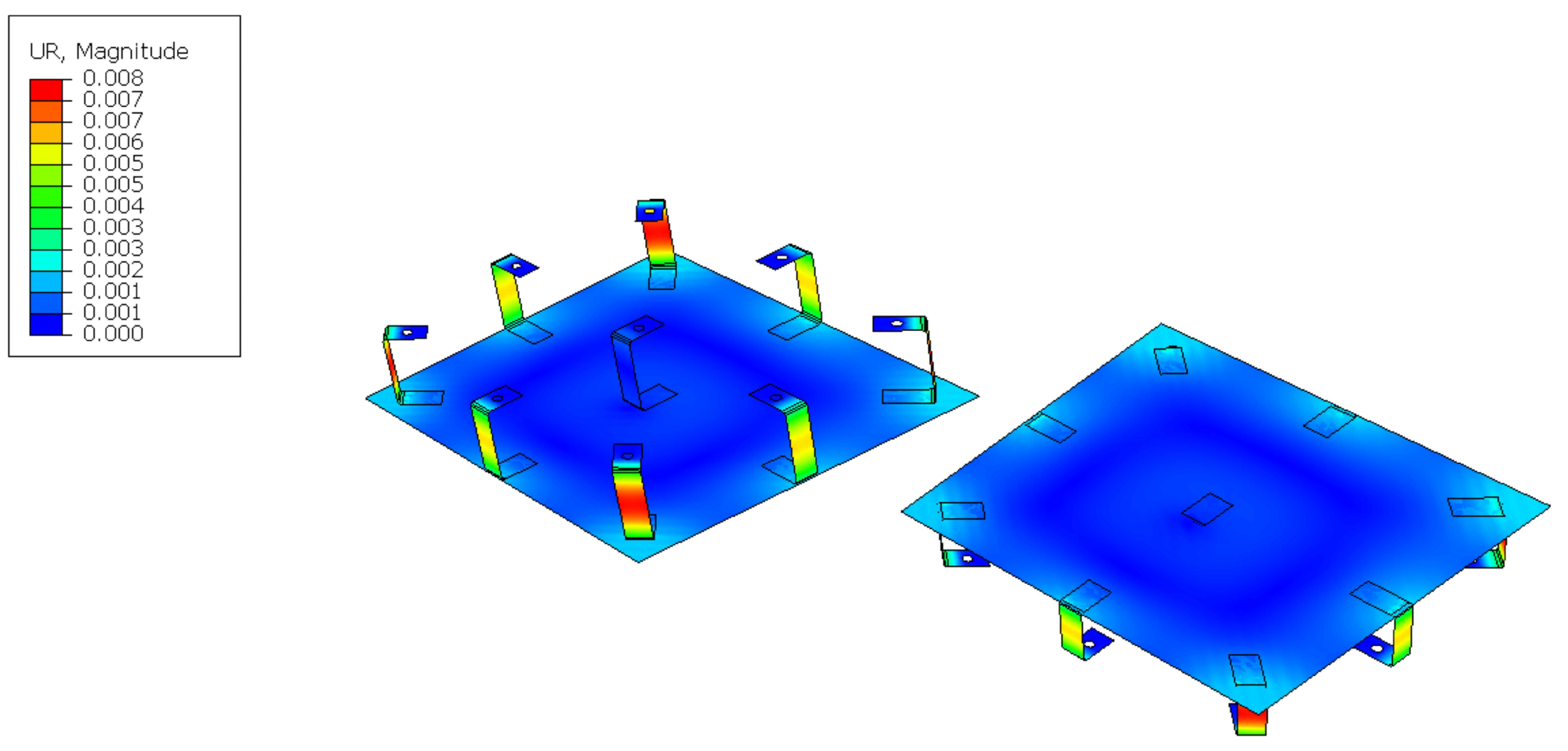
- Plate slope deviation mrad, to minimise beam quality loss and pointing errors.
- –
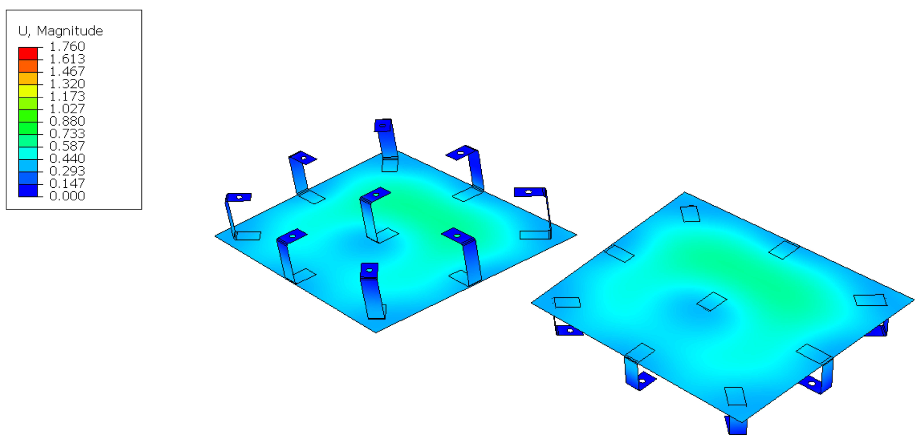
- Plate relative displacement mm, to minimise beam quality loss and pointing errors.
- If all the checks are satisfied, then the configuration is approved by the algorithm and the weld assessment is performed; otherwise, it is rejected.
3. Results
4. Discussion
5. Conclusions
- The optimisation procedure outputs only 4 of the analysed 700 configurations.
- Optimal values for bracket thickness and height have been found, corresponding to 3 mm and 200 mm, respectively.
- Only one configuration uses eight brackets and this implies the maximum plate thickness, i.e., 5 mm.
- Three configurations have nine brackets and the plate thickness is respectively 3 mm, 4 mm, and 5 mm.
- Thus, the configuration C_9_TC_3_HC_200_TP_3 could be selected as optimal since it also helps the welding of the brackets on the plate thanks to the same 3 mm thickness between the brackets and the plate.
Author Contributions
Funding
Data Availability Statement
Acknowledgments
Conflicts of Interest
References
- Haghghi, M.A.; Holagh, S.G.; Chitsaz, A.; Parham, K. Thermodynamic assessment of a novel multi-generation solid oxide fuel cell-based system for production of electrical power, cooling, fresh water, and hydrogen. Energy Convers. Manag. 2019, 197, 111895. [Google Scholar] [CrossRef]
- Almatrafi, E.; Khaliq, A.; Kumar, R.; Bamasag, A.; Siddiqui, M.E. Proposal and Investigation of a New Tower Solar Collector-Based Trigeneration Energy System. Sustainability 2023, 15, 7474. [Google Scholar] [CrossRef]
- Gledhill, S.; Hildebrandt, C.; Uhlig, R.; Wette, J.; Sutter, F. Secondary reflector tested at high temperatures and high radiation intensities. In Proceedings of the International Conference on Concentrating Solar Power and Chemical Energy Systems (SolarPACES) 2021, Online, 27 September–1 October 2021. [Google Scholar] [CrossRef]
- Fernandez-Garcia, A.; Cantos-Soto, M.E.; Roger, M.; Wieckert, C.; Hutter, C.; Martinez-Arcos, L. Durability of solar reflector materials for secondary concentrators used in CSP systems. Sol. Energy Mater. Sol. Cells 2014, 130, 51–63. [Google Scholar] [CrossRef]
- Siddiqui, M.E.; Almitani, K.H. Energy and Exergy Assessment of S-CO2 Brayton Cycle Coupled with a Solar Tower System. Processes 2020, 8, 1264. [Google Scholar] [CrossRef]
- German Aerospace Center (DLR) Institute of Solar Research. Solar Thermal Power Plants. 2021. Available online: https://www.solarpaces.org/wp-content/uploads/Study_Solar_thermal_power_plants_DLR_2021-05.pdf (accessed on 15 May 2023).
- Ben-Zvi, R.; Segal, A.; Epstein, M. Beam-Down Mirror: Thermal and Stress Analyses. J. Sol. Energy Eng. 2009, 131, 041003. [Google Scholar] [CrossRef]
- Zanut, A.; Binotti, M.; Giostri, A. Design and Optimization of a Point Focus Beam-Down System. Master’s Thesis, PoliMi, Milano, Italy, 2021. [Google Scholar]
- Calvet, N.; Slocum, A.H.; Gil, A.; Grange, B.; Lahlou, R.; Hamer, T.T.; Diago, M.; Tetreault-Friend, M.; Codd, D.S.; Trumper, D.L.; et al. Dispatchable Solar Power Using Molten Salt Directly Irradiated from Above. Sol. Energy 2021, 220, 217–229. [Google Scholar] [CrossRef]
- Diago, M.; Calvet, N.; Armstrong, P.R. Net power maximization from a faceted beam-down solar concentrator. Sol. Energy 2020, 204, 476–488. [Google Scholar] [CrossRef]
- Chirone, R.; Salatino, P.; Ammendola, P.; Solimene, R.; Magaldi, M.; Sorrenti, R.; Michele, G.D.; Donatini, F. Development of a Novel Concept of Solar Receiver/Thermal Energy Storage System Based on Compartmented Dense Gas Fluidized Beds. Engineering Conferences International. 2013. Available online: https://dc.engconfintl.org/fluidization_xiv/123 (accessed on 15 May 2023).
- Lahlou, R.; Armstrong, P.R.; Calvet, N.; Slocum, A.H.; Shamim, T. Testing of a secondary concentrator integrated with a beam-down tower system under non-liquid cooling strategies. In Proceedings of the SolarPACES 2017: International Conference on Concentrating Solar Power and Chemical Energy Systems, Santiago, Chile, 26–29 September 2017. [Google Scholar] [CrossRef]
- Wang, S.; Asselineau, C.A.; Fontalvo, A.; Wang, Y.; Logie, W.; Pye, J.; Coventry, J. Co-optimisation of the heliostat field and receiver for concentrated solar power plants. Appl. Energy 2023, 348, 121513. [Google Scholar] [CrossRef]
- Jafrancesco, D.; Sansoni, P.; Francini, F.; Fontani, D. Strategy and criteria to optically design a solar concentration plant. Renew. Sustain. Energy Rev. 2016, 60, 1066–1073. [Google Scholar] [CrossRef]
- Diaz-Heras, M.; Moya, J.D.; Belmonte, J.F.; Corcoles-Tendero, J.I.; Molina, A.E.; Almendros-Ibanez, J.A. CSP on fluidized particles with a beam-down reflector: Comparative study of different fluidization technologies. Sol. Energy 2020, 200, 76–88. [Google Scholar] [CrossRef]
- Diaz-Heras, M.; Barreneche, C.; Belmonte, J.F.; Calderon, A.; Fernandez, A.I.; Almendros-Ibáñez, J.A. Experimental study of different materials in fluidized beds with a beam-down solar reflector for CSP applications. Sol. Energy 2020, 211, 683–699. [Google Scholar] [CrossRef]
- Röger, M. Heliostat Performance Testing Guideline—Status Update in SolarPaces Task III Workshop. Santiago de Chile, 25 September 2017. Available online: https://elib.dlr.de/115415/ (accessed on 16 May 2023).
- Solar Paces Task III Measurement Of Solar Weighted Reflectance Of Mirror Materials For Concentrating Solar Powertechnology With Commercially Available Instrumentation. Available online: http://www.solarpaces.org/Tasks/Task3/Interim_Reflectance_Guideline.pdf (accessed on 16 May 2023).
- EN 1993-1-1:2005 +A1:2014. Eurocode 3: Design of Steel Structures. Available online: https://eurocodes.jrc.ec.europa.eu/EN-Eurocodes/eurocode-3-design-steel-structures (accessed on 14 April 2023).


| Parameter | Value |
|---|---|
| Basic wind speed (3 s gust) at 10 m above ground () | 45 m/s |
| Basic wind speed (10 min mean) at 10 m above ground () | 30 m/s |
| Bracket Thickness [mm] | Bracket Height [mm] | Plate Thickness [mm] | ||
|---|---|---|---|---|
| min | 6 | 1 | 80 | 1 |
| max | 9 | 5 | 200 | 5 |
| step | 1 | 1 | 20 | 1 |
| Configuration Name | Bracket Thickness [mm] | Bracket Height [mm] | Plate Thickness [mm] | |
|---|---|---|---|---|
| C_8_TC_3_HC_200_TP_5 | 8 | 3 | 200 | 5 |
| C_9_TC_3_HC_200_TP_3 | 9 | 3 | 200 | 3 |
| C_9_TC_3_HC_200_TP_4 | 9 | 3 | 200 | 4 |
| C_9_TC_3_HC_200_TP_5 | 9 | 3 | 200 | 5 |
| Configuration Name | Max Stress [MPa] |
|---|---|
| C_8_TC_3_HC_200_TP_5 | |
| C_9_TC_3_HC_200_TP_3 | |
| C_9_TC_3_HC_200_TP_4 | |
| C_9_TC_3_HC_200_TP_5 |
| Configuration Name | Max Stress [MPa] |
|---|---|
| C_8_TC_3_HC_200_TP_5 | |
| C_9_TC_3_HC_200_TP_3 | |
| C_9_TC_3_HC_200_TP_4 | |
| C_9_TC_3_HC_200_TP_5 |
Disclaimer/Publisher’s Note: The statements, opinions and data contained in all publications are solely those of the individual author(s) and contributor(s) and not of MDPI and/or the editor(s). MDPI and/or the editor(s) disclaim responsibility for any injury to people or property resulting from any ideas, methods, instructions or products referred to in the content. |
© 2023 by the authors. Licensee MDPI, Basel, Switzerland. This article is an open access article distributed under the terms and conditions of the Creative Commons Attribution (CC BY) license (https://creativecommons.org/licenses/by/4.0/).
Share and Cite
Pinello, L.; Fossati, M.; Giglio, M.; Cadini, F.; Bevilacqua, C.; Cilento, M.; Bassetti, F.; Magaldi, R. Structural Performance-Based Design Optimisation of a Secondary Mirror for a Concentrated Solar Power (CSP) Plant. Energies 2023, 16, 6000. https://doi.org/10.3390/en16166000
Pinello L, Fossati M, Giglio M, Cadini F, Bevilacqua C, Cilento M, Bassetti F, Magaldi R. Structural Performance-Based Design Optimisation of a Secondary Mirror for a Concentrated Solar Power (CSP) Plant. Energies. 2023; 16(16):6000. https://doi.org/10.3390/en16166000
Chicago/Turabian StylePinello, Lucio, Massimo Fossati, Marco Giglio, Francesco Cadini, Carla Bevilacqua, Mario Cilento, Fulvio Bassetti, and Raffaello Magaldi. 2023. "Structural Performance-Based Design Optimisation of a Secondary Mirror for a Concentrated Solar Power (CSP) Plant" Energies 16, no. 16: 6000. https://doi.org/10.3390/en16166000
APA StylePinello, L., Fossati, M., Giglio, M., Cadini, F., Bevilacqua, C., Cilento, M., Bassetti, F., & Magaldi, R. (2023). Structural Performance-Based Design Optimisation of a Secondary Mirror for a Concentrated Solar Power (CSP) Plant. Energies, 16(16), 6000. https://doi.org/10.3390/en16166000