Article

Research on an Error Compensation Method of SINS of a Mine Monorail Crane

1
School of Mechanical Electronic and Information Engineering, China University of Mining & Technology (Beijing), Beijing 100083, China
2
State Key Laboratory of Mechanical Behavior and System Safety of Traffic Engineering Structures, Shijiazhuang Tiedao University, Shijiazhuang 050043, China
3
Shijiazhuang Coal Mining Machinery Co., Ltd., Shijiazhuang 050043, China
4
School of Computer Science and Engineering, Southeast University, Nanjing 210096, China
*
Author to whom correspondence should be addressed.
Energies 2023, 16(16), 5969; https://doi.org/10.3390/en16165969
Submission received: 19 June 2023 / Revised: 9 August 2023 / Accepted: 10 August 2023 / Published: 13 August 2023

Abstract

:
Underground coal mines belong to the GNSS-denied environment, and the Strapdown Inertial Navigation System (SINS) has a significant advantage in the precise positioning of equipment in this environment because of its operation without requiring interaction with external information and strong anti-interference capabilities. Nonetheless, the vibrations of the installation platform adversely affect the positioning accuracy of SINS. This article focuses on the monorail crane in coal mines as the subject of research, developing a dynamic model for the motion unit consisting of the “track + drive unit + driver’s cab”, while analyzing the relationship between track roughness conditions and the vibration excitation of this unit. Subsequently, utilizing the dynamic model, the study calculated the angular and linear vibration characteristics and formulated models to address coning error and sculling error specific to the SINS in this vibration condition. Lastly, by employing a multi-sample compensation algorithm, this article compensated for positioning errors in the SINS caused by track roughness-induced vibrations during uniform straight-line motion of the motion unit, thus achieving optimal positioning information for the monorail crane. The simulation results demonstrated that employing a four-sample compensation algorithm reduces the coning error in SINS positioning calculations by a minimum of 50% and decreases the sculling error by at least 31%, satisfying the positioning accuracy requirements for precise parking of the monorail crane during the transportation phase, while establishing the foundation for autonomous precise positioning and integrated navigation of underground track transport equipment in coal mines.

1. Introduction

Coal is of paramount importance in China’s energy structure [1]. Traditional coal production processes include excavation, mining, and transportation, and with the development of intelligent mining operations, coal mining capacity has significantly improved, resulting in higher transportation demands [2].
Coal transportation entails two categories, main transportation and auxiliary transportation. The former refers to the carriage of raw coal whereas the latter encompasses the conveyance of equipment, personnel, and other materials [3]. The requirements for auxiliary transportation equipment are continually rising due to the increasing weight of comprehensive equipment. The monorail crane transportation system can achieve optimal transportation efficiency in environments characterized by significant fluctuations in the tunnels [4], the operational conditions of the monorail crane used in underground mining are illustrated in Figure 1.
Despite the requirement of human intervention during the transportation and loading and unloading processes, unmanned operation of the monorail crane transportation system is currently receiving considerable attention globally in the field of auxiliary transportation. This is due to the labor-intensive and inefficient nature of the process which necessitates the need for research towards reducing or eliminating personnel in the field. Precise positioning is a fundamental aspect of achieving unmanned autonomous operation of monorail cranes. Based on this, precise positioning can be utilized to achieve accurate parking of monorail cranes, thus reducing the manual handling workload during the transfer process and significantly enhancing work efficiency. Consequently, precise positioning serves as a crucial foundation for attaining unmanned operation of monorail cranes. Presently, the determination of the position within the designated interval of underground track transportation in coal mines is carried out by calculating the mileage encoder. In comparison, for monorail crane transportation, the interval the crane is located at is determined through the Radio Frequency Identification (RFID) reader it carries that reads the RFID tag on the rail [5]. An accuracy of up to meters can be achieved by the monorail crane using this positioning method. However, to further enhance positioning accuracy, denser placement of RFID tags on the rail is required, which could raise construction difficulty and cost. Moreover, changes in the speed of the monorail crane and environmental noise can interfere with the communication between the RFID reader and tags. Hence, the tag reading might fail, leading to imprecise location information of the monorail crane and eventual positioning failure.
For instance, Song Baoyan et al. [6] introduced a logical regional temporal relationship model for addressing missed detection problems in RFID-tagged tracking of the crane; the proposed method identifies the most likely composite events that satisfy the time constraints, thereby preventing missed detection. Zhang Junren [7] developed a method for remote monitoring and real-time positioning of motor vehicles that combines inertial positioning navigation technology with wireless communication. Niu Yingli [8] utilized the acceleration sensor and gyroscope in the inertial navigation system to collect data on underground vehicle movement, trajectory, and speed. The SINS utilizes gyroscopes and accelerometers to measure the angular and linear motion information of the carrier, enabling the calculation of its heading, attitude, and position. The working process does not rely on external information or the need for a reference transmission medium. As a result, it exhibits a high level of resistance to environmental interference, thereby making it highly suitable for demanding underground working environments in coal mines [9]. In the earlier mentioned research, the utilization of the SINS in underground coal mines is limited to parameter extraction solely from the speedometer and gyroscope outputs. Subsequently, the system estimates the position and trajectory of the carrier. Nevertheless, the vibrations and instability experienced by the carrier during operations can adversely affect the SINS, leading to significant drift in the mathematical platform and resulting in calculation errors that detrimentally impact measurement accuracy [10]. The literature mentioned above did not account for compensating for this error, leading to constrained trajectory fitting and positioning accuracy.
The monorail crane track consists of a combination of steel I-beams for lifting, as illustrated in Figure 2.
Based on the above analysis, it is clear that the structure and lifting form of this type of monorail crane would cause unevenness in the running track. The main reasons are as follows:
(1) The running track of the monorail crane is suspended from an anchor cable by means of a chain, and the anchor cable is fixed to the top of the roadway by an anchor rod. This fixed form causes the track to rise and fall with the suspension point;
(2) The entire running track is made up of multiple segments of I-beams that are overlapped. In order to cushion the impact force during the operation of the monorail crane, V-shaped gaps need to be left at the interfaces of the steel beams. The gaps and displacement at the interfaces will inevitably cause unevenness in the running track;
(3) The layout of the roadway for the monorail crane is relatively complex, and the ups and downs and trends of the roadway will also cause the track to be uneven.
In addition, the locomotive part of the monorail crane is also suspended under the driving unit, and the multi-DOF center of gravity swing during the movement will also cause instability in the operation.
For different disturbance environments, different compensation algorithms are required for the calculation of the SINS. Miller [11] proposed a three-subsample optimization algorithm for the equivalent rotation vector in conical motion environments. Based on his research, Musoff [12] analyzed the criteria used to evaluate optimization algorithms in classical cone motion environments. Additionally, quantitative mathematical models regarding the attitude update period, cone motion frequency, and algorithm drift were summarized. Savage [13,14] investigated the coning error compensation algorithm, while Park [15] proposed a formal method for determining the optimal coefficients in conical algorithms. The aforementioned research on the coning error in SINS carries a certain degree of representativeness. Research on the compensation of sculling errors is relatively scarce, and the compensation of coning errors solely relying on specific frequencies fails to effectively mitigate vibrations in complex environments.
The SINS is prone to system vibrations in special environments, which hinders its accuracy and requires precise compensation. Obtaining the monorail crane carrier’s vibration profile is essential to achieve accurate compensation. Yang Hai [16] developed a dynamic model for a double drum shearer by analyzing the forces acting on it during cutting. They used this model to perform error compensation for the SINS used in shearer positioning based on the shearer’s vibration characteristics. The suspended track’s poor rigidity leads to a diverse range of complex angular and linear vibrations during the monorail crane’s operations. To identify the exact form of these vibrations, it is crucial to analyze the crane’s operations dynamically. Quan Fei [17] utilized Pro/E to establish a 3D model of the electric traction monorail drive system and simulated its dynamics using ADAMS2015. They investigated the vibration acceleration’s changing pattern of the driving system under different operating environments. By applying the multibody dynamics theory and UM (version: 8.2.0.7), Huang Hai [18] developed a dynamic model for ground-suspension monorail vehicles and investigated how the suspended monorail vehicles’ running stability is affected by various working and road conditions. Wang Lidong et al. [19] suggested a conical error compensation algorithm to decrease misalignment and improve accuracy in SINS on a swing base. The SINS is installed on the driver’s cab of the monorail crane in this article. Previous studies primarily focused on the vibration of the suspended monorail locomotive’s driving part, neglecting to consider the track and lifting components as a comprehensive unit. Consequently, accurately calculating the vibration at the SINS’s installation platform and compensating for position calculation errors becomes infeasible. Moreover, the existing research on compensating for vibration in the SINS installation base is predominantly focused on linear vibrations, paying insufficient attention to the angular vibrations that greatly interfere with the SINS’s position calculation process on the monorail crane.
This paper proposes an operational characteristic-based compensation strategy for SINS errors in monorail cranes. The forces acting on the end-moving unit of the “track + driving unit + driver’s cab” in a monorail crane were analyzed, and a dynamic model was established using Lagrange’s method to solve the angular and linear vibration characteristics. The paper proposes a SINS cone-shaped error compensation model based on the angular vibration characteristics and a paddle-shaped error compensation model based on the angular and linear vibration characteristics. Various compensation algorithms were used to simulate and analyze the error compensation for the monorail crane’s SINS using different numbers of sub-samples. The paper’s innovation is the establishment of a multi-body dynamics model for the end-moving unit of the “track + driving unit + driver’s cab”, which considers the monorail crane’s motion state and force situation. Simulations were conducted to validate the multi-sample error compensation algorithm, which improved the SINS’s resolution accuracy in this application scenario under angular and linear vibration conditions.

2. Dynamic Analysis of Monorail Crane

The monorail crane is considered an essential piece of auxiliary transportation equipment in underground coal mines, owing to its capacity for strong loadbearing and excellent trafficability. As illustrated in Figure 3, the monorail crane locomotive comprises various components, including front and rear driver’s cabs, driving unit, pull rod assembly, main engine, and auxiliary cars. The main engine is equipped with an explosion-proof diesel engine system, a hydraulic system, and an automatic fire extinguishing system. Meanwhile, the auxiliary car houses an electronic control system. The pull rods, pin axles, and articulated bearings are fundamental to connecting the individual units.

2.1. Analysis of Monorail Crane Motion

Figure 4 illustrates the arrangement of the primary components responsible for driving the monorail crane located in the driving unit. The driving unit is comprised of various components, including bearing wheelsets, brake blocks, braking arms, braking devices, driving wheels, guide wheels, clamping oil cylinders, radial piston motors, and other equipment. Friction between the drive wheel and the track is essential for the operation of the monorail crane. The clamping force generated by the clamping oil cylinder allows the driving wheel to grip the ribs of the suspended track above the roadway. Through the hydraulic motor, the driving wheel produces rolling friction with the track, generating torque to propel the machine and facilitate motion.
The driver’s cabin of the monorail crane is positioned beneath the driving unit of the equipment. Figure 5 depicts the selection of the center of gravity of the driver’s cabin for the establishment of a dynamic coordinate system. The vibrations of the driver’s cabin in the monorail crane can be classified into six distinct degrees of freedom when using the aforementioned coordinate system as a reference. These are as follows:
The corresponding degrees of freedom expression parameters for the abovementioned movements are shown in Table 1, among which the degrees of freedom that mainly affect the motion stability of the “driving unit + driver’s cab” are the transverse, heave, roll, pitch, and yaw movements.

2.2. Force Analysis of Monorail Crane Wheel Set

The driving unit of the monorail is responsible for conducting different functions such as traveling, braking, acceleration, and steering by utilizing various wheelsets that interact with the web plate of the track beam. The traction necessary for monorail travel is consequently produced by the cooperation between the wheelset and the track [20].
The wheelset, being a complicated, viscous, and elastic structure, possesses apparent nonlinear mechanical features. The conventional Coulomb friction theory cannot be applied in this scenario [21]. To simplify the complexity of the treatment, it is generally inferred that the wheelset manifests linear characteristics given the state of small deformation. Thus, this research presumed the following fundamental assumptions for the wheelset model [22]:
(1) The deformation of the wheelset during the motion process is very small, which belongs to micro-vibration. The axial stiffness of all wheelsets is linear, and the influence of the vertical load was ignored;
(2) The radial stiffness and damping of the drive wheel, guide wheel, and support wheel were considered.
Given the above presumptions, the radial model of the wheelset can be reduced to a point contact linear damping model, as depicted in Figure 6. One end is secured to the framework using a bearing while the other is linked to the track web surface. The force state can be observed in Figure 7 and embraces the compression force, the relevant positive pressure response force, the operating resistance, the friction force, and the rolling friction couple moment [23].

2.3. Establishment of Dynamic Model for the Driving Part of Monorail Crane

The driving part of a monorail crane is a complex multi-degrees-of-freedom system. When the monorail crane runs along the lifting steel rail, it will generate very complex vibrations. In order to establish a more reasonable dynamic model of the monorail crane, it is necessary to assume and simplify the physical model of the monorail crane driving part when the real mechanical characteristics of the connections between the components of the monorail crane cannot be fully obtained. The basic assumptions are as follows:
(1) Concentrate the mass of each main module connected to the driving part at the center of mass, and simplify it as a concentrated mass m 1 , m 2 , m 3 (i.e., the mass of the driver’s cab hanging below the driving part, the driving part and track);
(2) Assuming that the top plate is connected to the running track, and the driving part is connected to the functional module installed below through massless elastic components, and based on the linear damping model of the wheelset and track contact, k 1 represents the stiffness between the top plate and the running track, k 2 represents the stiffness between the bearing wheel and the track surface, k 3 represents the stiffness between the friction driving wheel and the track surface, k 4 represents the stiffness between the guide wheel and the track surface and k 5 represents the connection stiffness between the driving part and the lower mounted functional module;
(3) Assuming that the top plate is connected to the running track, and the driving part is connected to the functional module installed below through massless elastic components, and based on the linear damping model of the wheelset contacting the track, c 1 represents the damping between the top plate and the running track, c 2 represents the damping between the bearing wheel and the track surface, c 3 represents the damping between the friction driving wheel and the track surface, and c 4 represents the damping between the guide wheel and the track surface c 5 represents the damping between the driving part and the lower mounted functional module;
(4) The monorail crane moves at a constant speed along the surface of the hard steel rail beam, without considering the effect of longitudinal force. Throughout the entire process, the driving wheel sets always maintain contact with the side of the rail beam;
(5) During the operation of a monorail crane, the deformation of each wheelset is very small, so the elastic damping of all wheelsets is calculated based on linear spring and viscous damping, and the influence of vertical load changes on stiffness characteristics is ignored;
(6) During the operation of the monorail crane, the entire system undergoes small amplitude vibration at the basic equilibrium position, with a symmetrical system structure and equal parameters.
(7) The elastic deformation of the running track of the monorail crane is not considered.
Considering that the driver’s cab is the terminal component of the complete monorail transport system, it is intended to have an inertial navigation system installed within it. Therefore, the motion of the monorail along the track is a comprehensive dynamic system consisting of the driving unit and the steel frame of the cabin. As illustrated in Figure 8, dynamic models from three different viewing angles of the system were developed.
For the dynamic system with multiple degrees of freedom mentioned above, the Lagrange energy equation and the d’Alembert principle were used for analysis:
d d t ( T q ˙ j ) T q j + U q j + D q ˙ j = Q j
where T is kinetic energy; q j is a generalized coordinate variable; Q j is the generalized force; U is the potential energy; and D is the dissipated energy of the system.
The vibration of the system in the z -direction under pitching motion can be solved by equations of motion. As shown in Figure 8a, the Equations of motion of linear vibration and angular vibration of the monorail crane cab are established.
(1) The kinetic energy of the end motion unit composed of the cab, driving part, and track of a monorail crane in the z -direction:
T c = 1 2 m 1 z 1 2 + 1 2 m 2 z 2 2 + 1 2 m 3 z 3 2 + 1 2 J y θ ˙ c 2
(2) The elastic potential energy of the end motion unit composed of the cab, driving part, and track of a monorail crane in the z -direction:
U = 1 2 ( 2 k 5 ) ( z A z 2 ) 2 + 1 2 ( 2 k 5 ) ( z B z 2 ) 2 + 1 2 ( 4 k 2 ) ( z 2 z 3 ) 2 + 1 2 ( 2 k 1 ) z 3 2
(3) The dissipated energy of the end motion unit composed of the driver’s cab, driving part, and track of a monorail crane in the z -direction:
D = 1 2 ( c 5 2 ) ( z ˙ A z ˙ 2 ) 2 + 1 2 ( c 5 2 ) ( z ˙ B z ˙ 2 ) 2 + 1 2 ( c 2 3 4 ) ( z ˙ 2 z ˙ 3 ) 2 + 1 2 ( c 1 2 ) z 3 2
According to the structural relationship in the diagram,
z A = z 1 + a 1 θ c
z B = z 1 a 2 θ c
By substituting the given formulas into Equation (1), we can derive the linear vibration equation in the z -direction for the monorail crane drive system, and the monorail crane operator cabin’s linear and angular vibration equations in the z -direction. Solving these equations simultaneously allows us to obtain the vibration equation system of the unit in the z -direction, which is the z-direction dynamic coupling model in the pitch state.
{ m 2 z ¨ 2 2 k 5 ( z A z 2 ) 2 k 5 ( z B z 2 ) + 4 k 2 ( z 2 z 3 ) ( c 5 2 ) ( z ˙ A z ˙ 2 ) ( c 5 2 ) ( z ˙ B z ˙ 2 ) + ( c 2 3 4 ) ( z ˙ 2 z ˙ 3 ) = 0 m 1 z ¨ 1 + 2 k 5 ( z A z 2 ) + 2 k 5 ( z B z 2 ) + ( c 5 2 ) ( z ˙ A z ˙ 2 ) + ( c 5 2 ) ( z ˙ B z ˙ 2 ) = 0 J y θ ¨ c + 2 k 5 a 1 ( z A z 2 ) 2 k 5 a 2 ( z B z 2 ) + ( c 5 2 ) a 1 ( z ˙ A z ˙ 2 ) ( c 5 2 ) a 2 ( z ˙ B z ˙ 2 ) = 0
where z 3 represents the vertical displacement of the monorail track during operations; this phenomenon triggers an uneven track and destabilizes the monorail’s movement, hence affecting the mathematical platform of the inertial navigation system. This paper refers to the notion of road surface irregularities and employs the unevenness coefficient of the track surface to characterize and determine the excitation signal caused by the bumpy rail surface. In China, the white noise of Gaussian distribution is often utilized to represent the contact excitation of the striking surface [24].
Z ˙ g ( t ) = 2 π [ u G q ( n 0 ) w ( t ) f 0 Z g ( t ) ]
where Z g ( t ) is the displacement input excitation of the contact surface; Z ˙ g ( t ) is the velocity input excitation of the contact surface; f 0 is the input frequency; and w ( t ) is random excited white noise with a mean of 0. According to Equation (8), a corresponding contact surface model was built in Simulink, and white noise was used as the input signal to stimulate the built monorail crane drive and cab end unit system. The resulting incentive model is shown in Figure 9.
This article cites the classification criteria for contact surface unevenness for grading, as shown in Table 2.
By incorporating the eight levels of contact surface roughness classification criteria into the model, the input curves of each level of contact surface roughness at unit speed are obtained, as shown in Figure 10:
As shown in Figure 10, when the irregularity level was 6, the maximum irregularity displacement of the track in the z-direction was 0.019 m, which is more in line with the vibration situation of the track during the operation of the monorail crane. The six-level model was used as the excitation signal for the track irregularity.
By using the abovementioned methods, we can obtain the vibration situation in the z and y directions of the system in the roll motion state, as well as the vibration situation in the y direction of the system in the swing state, and obtain its corresponding dynamic model.

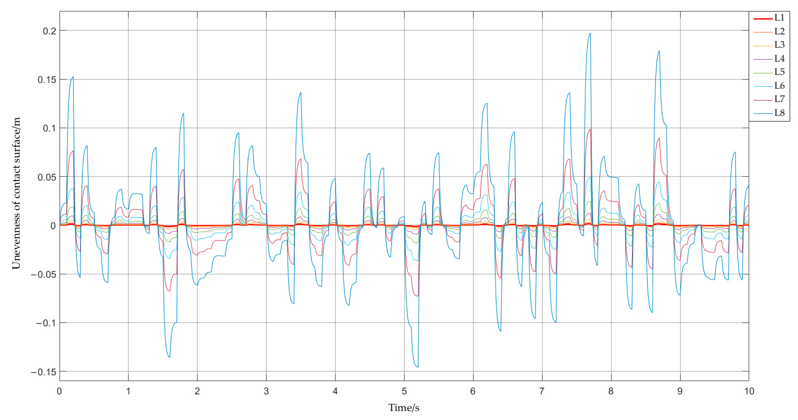
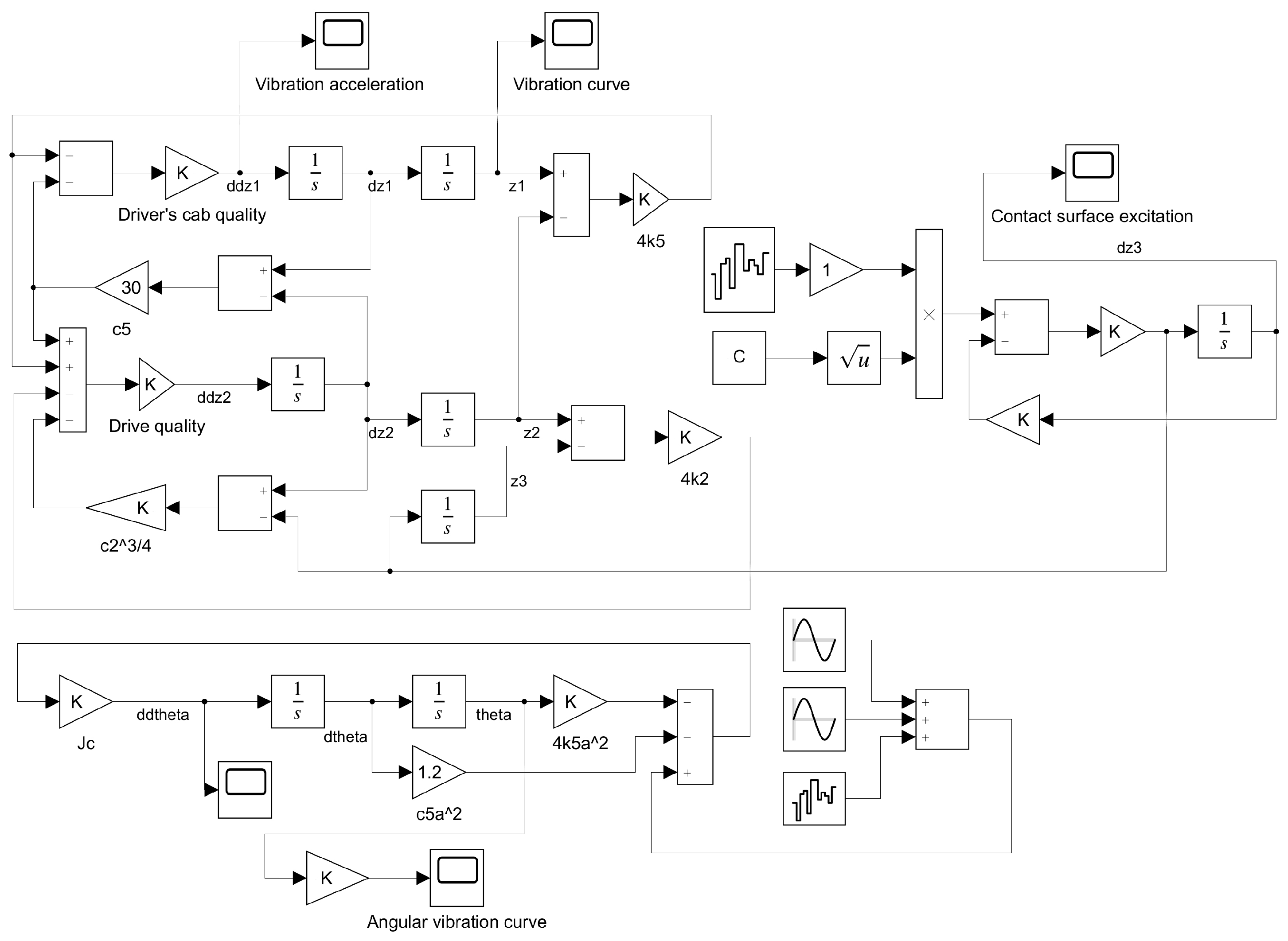
2.4. Solving the Dynamic Model of Monorail Crane

As shown in Figure 11, a multi-body dynamic model of the motion unit “track + driving unit + driver’s cab” was constructed in Simulink according to Equation (7).
After inputting the actual parameters into the model, we simulated the linear and angular vibrations of the driver’s cab caused by track irregularity under a uniform linear motion of 2 m/s for the “track + driving unit + driver’s cab” motion unit, as shown in Figure 12 and Figure 13.
From the two above-shown Figures, it can be seen that during the operation of the monorail crane, the amplitude of the line vibration in the driver’s cab in the Z direction was between −0.18 m and 0.19 m, and the amplitude of the cab angle vibration was between −1.1° and 1.6°. The above-shown line vibration and angle vibration curves can be decomposed into the superposition of multiple sinusoidal components of different frequencies and random noise, as shown in the following expression:
W j ( t ) = i = 1 m L i sin ( ω W i t + ε i ) + v W ( t )
T j ( t ) = i = 1 m M i sin ( ω A i t + φ i ) + v T ( t )
where W j ( t ) and T j ( t ) are the angular and linear vibration of the monorail driver’s cab, respectively; L i and M i are the amplitude of angular vibration and linear vibration frequency components, respectively; ω W i and ω A i are the angular frequencies of different frequency components; ε i and φ i are the phase angles of angular vibration and linear vibration, respectively; v W ( t ) and v T ( t ) are the angular vibration and linear vibration noise; and j = X , Y , Z represents the three directions of the axes.

3. Compensation for Calculation Error of Monorail Crane SINS

The SINS does not rotate around a fixed axis during operation. Instead, it undergoes rotational movements along the three axes of the carrier coordinate system in space, making the entire process non-fixed-axis motion. The errors in SINS computation, caused by the line and angular vibration of the motion, are the primary factors that affect its precision. The carrier’s angular vibration during operation impacts the coning error in attitude update calculation. Meanwhile, angular and line vibrations both cause sculling errors, which affect calculation updates for speed and position.

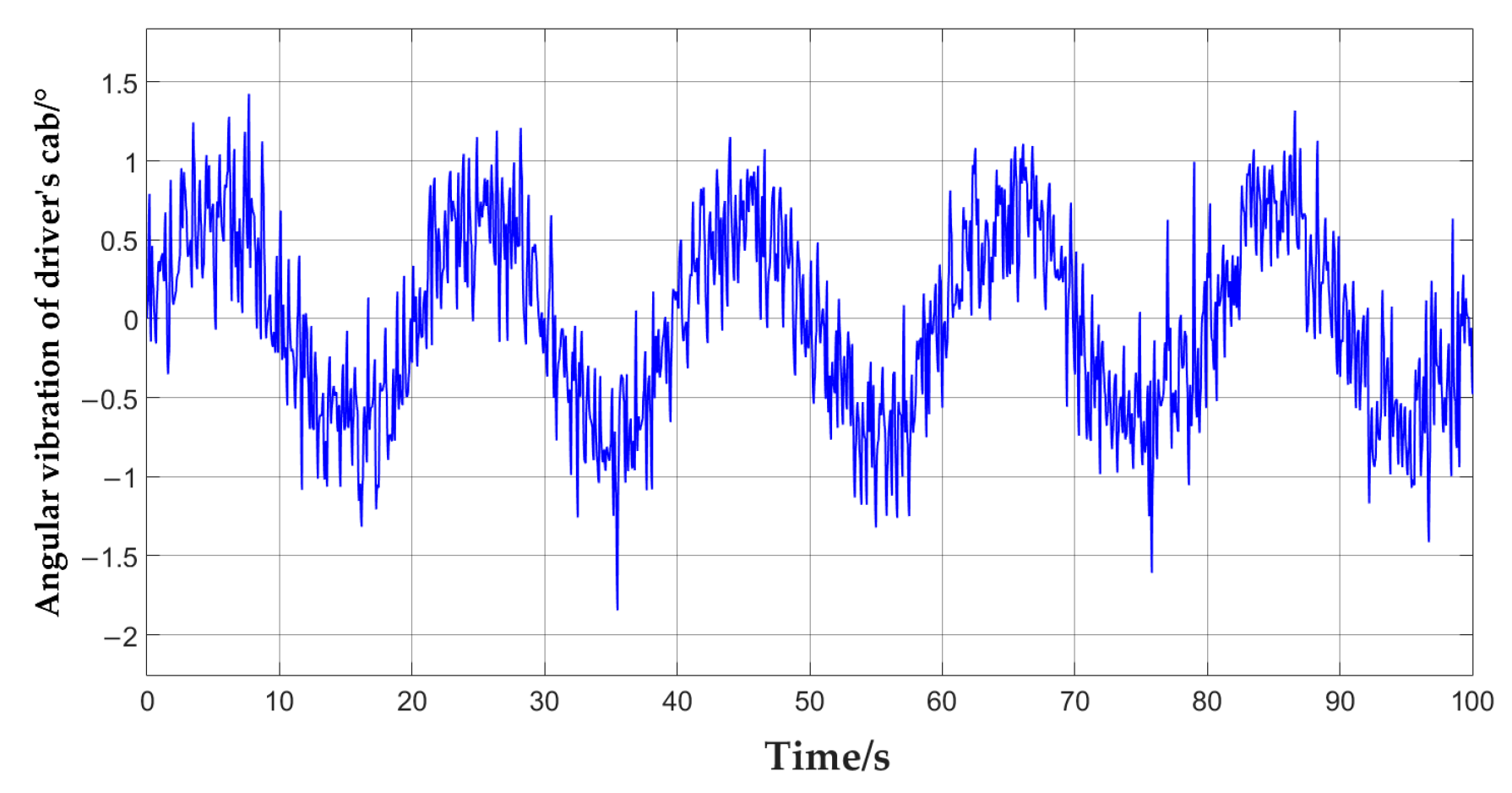
3.1. Compensation Algorithm for Angular Vibration

The rotation or attitude transformation of the steel body under two coordinate systems can be described by utilizing quaternions, which are composed of four elements, in reference to the driver’s cab coordinate system of the monorail as the b-axis, the navigation coordinate system as the n-axis, and the inertial coordinate system as the i-axis.
A quaternion can be represented in trigonometric form as
Q = q 0 + q v = cos θ 2 + u sin θ 2
The angular velocity from the carrier b coordinate system to the n coordinate system can be derived:
ω n b b ( t ) = 2 Q b n * ( t ) Q ˙ b n ( t ) = K sin θ [ sin K t cos K t tan θ 2 ] T
where Q b n * ( t ) is the conjugate form Q ˙ b n ( t ) , and the comparison Equation (11) has
Q n b ( t ) = cos θ 2 + θ ( t ) θ sin θ 2
We can then obtain
θ ( t ) = θ [ cos K t sin K t 0 ] T
The above-shown equation indicates that at time t, the carrier coordinate system b rotates θ ° around the unit rotation axis on the OXnYn plane of the reference coordinate system n, where
u ( t ) = θ ( t ) / θ = [ cos K t sin K t 0 ] T
At this time, the direction of the rotation axis is constantly changing, but the rotation angle remains constant. The zb axis of the moving coordinate system draws a conical surface, which is the reason for the conical motion.
The quaternion update equation set within a certain update period T is
Q ( t n ) = Q ( t n 1 ) Q ( T )
where T = t n t n 1 indicates the renewal period and Q ( T ) indicates the quaternion increment in this period. Multiplying both sides of the above equation by Q ( t m 1 ) , we can obtain
Q ( T ) = Q ( t n 1 ) Q ( t n ) = [ 1 2 ( sin θ 2 sin KT 2 ) 2 sin θ sin KT 2 sin K ( t n T 2 ) sin θ sin KT 2 cos K ( t n T 2 ) sin 2 θ 2 sin K T ]
Suppose θ ( T ) is the equivalent rotation vector of change in T = [ t n 1 , t n ] :
When θ and K T are both small quantities, then the approximate is θ ( T ) θ K T , and the equivalent rotation vector can be approximated as
θ ( T ) = θ ( T ) sin θ ( T ) 2 [ sin θ sin K T 2 sin K ( t n T 2 ) sin θ sin K T 2 cos K ( t n T 2 ) sin 2 θ 2 sin K T ] 2 [ sin θ sin K T 2 sin K ( t n T 2 ) sin θ sin K T 2 cos K ( t n T 2 ) sin 2 θ 2 sin K T ]
By integrating the diagonal velocity Equation (12), the angular increment within the time period of the equivalent rotation vector calculation can be obtained:
Δ α T = t n 1 t n ω n b b ( t ) d t     = [ 2 sin θ sin KT 2 sin K ( t n T 2 ) 2 sin θ sin KT 2 cos K ( t n T 2 ) 2 K T sin 2 θ 2 ]
Comparing Equation (27) with Equation (28), it can be seen that the x-axis and y-axis components are exactly the same, while there is a difference in the z-axis. This difference can cause errors when using angle increments instead of rotation vectors for attitude updates and these can accumulate over time. Here, the error is defined as
δ θ T = θ ( T ) Δ α T = [ 0 0 2 sin 2 θ 2 ( K T sin K T ) ]
To compensate for this error, a multi-sample compensation algorithm is usually used; with N samples taken within [ t , t + h ] , the sampling interval is h = T / N , and according to Equation (28), the angular increment within each sampling interval can be obtained, which is the sub-sample.
Δ θ n i = t n 1 + ( i 1 ) h t n 1 + i h ω n b b ( t ) d t = [ 2 sin θ sin K h 2 sin K ( t n 1 + i h h 2 ) 2 sin θ sin K h 2 cos K ( t n 1 + i h h 2 ) 2 K h sin 2 θ 2 ]
Cross multiply the angular increments of different sub-samples, assuming that θ and K h are both small quantities, and the cross product is shown in Equation (31).
Δ θ n i × Δ θ n j [ ( i j ) ( θ K h ) 3 2 sin K ( t n 1 + i + j 1 2 h ) ( i j ) ( θ K h ) 3 2 cos K ( t n 1 + i + j 1 2 h ) 4 K h sin 2 θ sin 2 K h 2 sin ( i j ) ]
The x-axis and y-axis components are sinusoidal fluctuations over time, while the z-axis components are minimum constant values related to the sample interval ( i j ) . Therefore, we can infer that the cross-product of different sub-samples can provide a certain angular increment compensation effect in the z-axis direction. Therefore, we estimated and compensated Equation (20) using the sum of the cross products between all subsamples in [ t n 1 , t n ] , denoted as
δ θ ( T ) = j = 2 N i = 1 j 1 k i j Δ θ n i × Δ θ n j
Among them, k i j is the undetermined coefficient, known as the cone error compensation coefficient. From Equation (22), it can be found that the z-axis component is independent of absolute time and only related to the interval between sub-samples. Therefore, Equation (23) can be simplified as
δ θ ( T ) = i = 1 N 1 k N i Δ θ n i × Δ θ n N
Table 3 shows the error compensation coefficients of the sub-sample algorithm [25].

3.2. Linear Vibration Compensation Algorithm

During the movement of a monorail crane, angular vibration and linear vibration caused by track irregularity can be regarded as linear vibration along the z-axis and angular vibration around the x-axis in the carrier coordinate system b, both of which have the same frequency but different phase π / 2 , and angular velocity and linear velocity are, respectively,
ω i b b ( t ) = [ α K sin K t 0 0 ]
f s f b ( t ) = [ 0 0 β K cos K t ]
By integrating Equations (25) and (26), the angular increment and specific force increment can be obtained as follows:
Δ θ i b b ( t ,   t n 1 ) = t n 1 t ω i b b ( τ ) d τ = [ α ( cos K t cos K t n 1 ) 0 0 ]
v s f b ( t ,   t n 1 ) = t n 1 t f s f b ( τ ) d τ = [ 0 0 β ( sin K t sin K t n 1 ) ]
If Equations (27) and (28) are incorporated into the calculation equation for sculling error [26], there will be
Δ v s c u l ( n ) b ( n 1 ) = 1 2 t n 1 t n Δ θ i b b ( t , t n 1 ) × f s f b ( t ) + v s f b ( t , t n 1 ) × ω i b b ( t ) d t                                 = 1 2 t n 1 t n [ Δ θ i b b ( t , t n 1 ) + v s f b ( t , t n 1 ) ] × [ f s f b ( t ) + ω i b b ( t ) ] d t
Formally, it is identical to the non-commutative error under conical motion; therefore, the coefficients of the coning error compensation algorithm can be applied to the compensation of sculling error. Set Y n i = Δ θ n i + Δ v n i , and according to Equation (24), the N sub-sample sculling error compensation algorithm can be obtained:
Δ v s c u l ( n ) b ( n 1 ) = i = 1 N 1 k N i Y n i × Y n N = i = 1 N 1 k N i ( Δ θ n i + Δ v n i )   ×   ( Δ θ n N + Δ v n N )
Especially under sculling conditions, Δ θ n i × Δ θ n N = Δ v n i × Δ v n N = 0 So, by expanding Equation (30), it can be concluded that
Δ v ^ s c u l ( n ) b ( n 1 ) = i = 1 N 1 k N i Δ θ n i × Δ v n N + i = 1 N 1 k N i Δ v n i × Δ θ n N
where k N i is the same as the cone error compensation coefficient in Table 3.

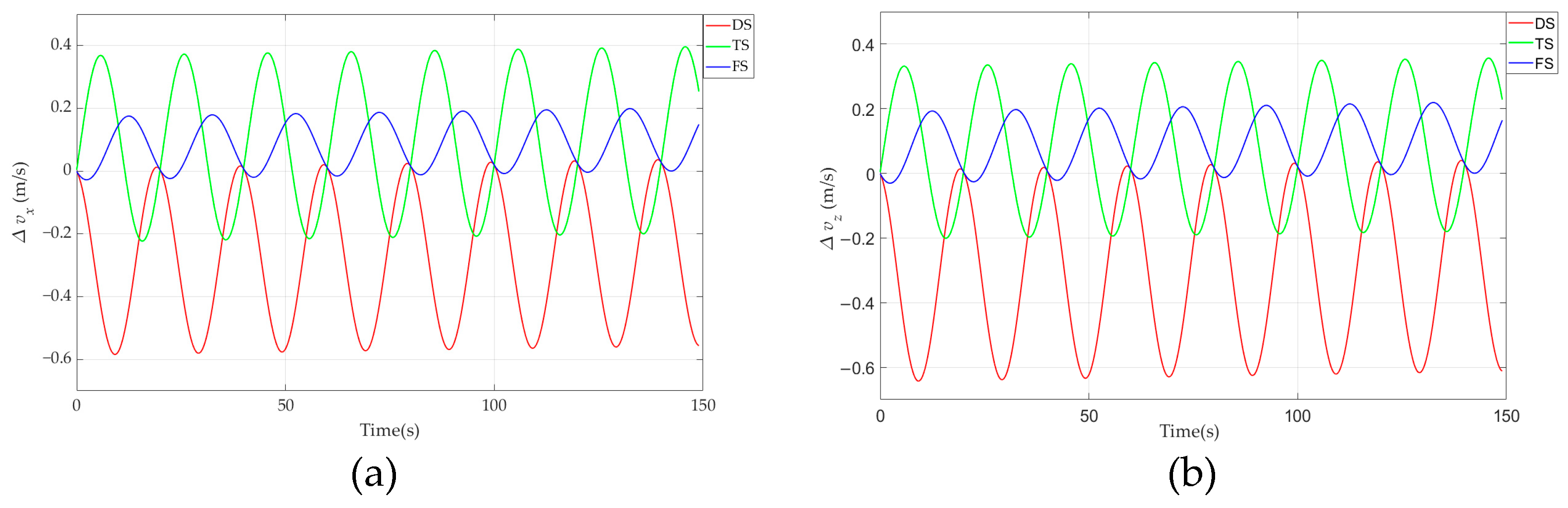
4. Simulation Analysis of Multiple Subsample Compensation Algorithm

In order to verify the effectiveness of the multi-sample error compensation algorithm proposed earlier in compensating for linear and angular vibrations during the operation of a monorail crane, as the single sample compensation method did not calculate the cross product between angular increments, it could not reflect the advantages of the compensation algorithm. Therefore, the two-sample, three-sample, and four-sample models were selected for error compensation simulation.
This time, the operation status of the DC280-160Y explosion-proof diesel engine monorail crane was taken as the object, and its motion status on a uniform speed of 2 m/s straight road was simulated. Strapdown inertial navigation takes the FOSN fiber optic strapdown inertial navigation system produced by Aerospace Science and Industry Group as the parameter sample, and the constant drift of the fiber-optic gyroscope is 0.01, random drift is 0.005, and the constant drift of quartz accelerometer is 30 μg; the random drift is 30 μg, and the data sampling frequency is 100 Hz. The simulation location is 116°20′ E and 39°56′ N. Gravitational acceleration g = 9.82840944. The radius of curvature of the meridian circle RM = 6,361,840.46; the curvature radius of the prime vertical RN = 6,397,829.93; Earth’s rotation angle speed is w = 7.292115 × 10⁻⁵  r a d / s ; the simulation time is 150 s, and according to the track irregularity excitation simulated above, the angular frequency of cone motion is π / 10 :
Figure 14 shows the error curves of SINS in different directions during the movement of a monorail crane using a conic error compensation algorithm with different numbers of sub-samples. (a) represents the error curve in the X direction, (b) represents the error curve in the Y direction, and (c) represents the error curve in the Z direction.
Figure 14 presents the error curves of three compensation algorithms: the DS curve represents the two-sample algorithm, the TS curve represents the three-sample algorithm, and the FS represents the four-sample algorithm. The compensation accuracy values indicate that the four-sample algorithm achieved the highest accuracy in all three directions, as shown in Table 4.
With an increase in the number of samples, the statistical characteristics of the cone error in the three directions reduced. Moreover, the three-sample and four-sample compensation algorithms were superior to the two-sample algorithm. The four-sample algorithm improved the error compensation effectiveness in the three directions by 54%, 58%, and 49% respectively. These results meet the requirements of cone error compensation of SINS during the movement process of the monorail crane and the driver’s cab. Therefore, we recommend selecting the four-subsample compensation algorithm for compensating the coning error of SINS during the monorail crane’s straight-line uniform speed travel.
Figure 15 displays the error compensation algorithm for SINS rowing in various directions during the motion of a monorail crane using different quantum samples as shown below. This error compensation algorithm generates speed error curves in the X, Y, and Z directions, labeled (a), (b), and (c), respectively.
Table 5 lists the statistical characteristics of these curves. The four-sample compensation algorithm significantly improves performance in the compensation for sculling errors in all three directions. In comparison to the two-sample algorithm, accuracy in compensating for errors in the X, Y, and Z directions increased by 75%, 59%, and 64%, respectively. When compared to the three-sample algorithm, accuracy for compensating for errors in the X, Y, and Z directions increased by 31%, 59%, and 38%, respectively. In conclusion, the four-sample compensation algorithm significantly improved the compensation effect, and it effectively compensated for the sculling error during the uniform linear motion of a monorail crane.

5. Conclusions

This paper discusses the severe impact of the unevenness of the track on the SINS of the monorail crane and proposes a multi-body dynamics model for the motion unit at the end of the monorail crane consisting of “track + driving unit + driver’s cab”. We introduced a compensation method for coning and sculling errors of the SINS in this context. Specifically, we established a dynamic model of the moving unit at the end of the monorail and analyzed the characteristics of angular and linear vibration that occur during operation. The results of our simulations indicate that the four-sample compensation algorithms significantly improve the coning and sculling error compensation compared with the two-sample and three-sample compensation algorithms.
By effectively compensating for the positioning calculation errors caused by uneven track vibrations, the SINS installed on the monorail crane can improve the accuracy of the inertial navigation system’s output position information. The position errors of the SINS output on the monorail crane, after error compensation, can be controlled within 0.16 m and the angle errors within 2 degrees, essentially meeting the accuracy requirements for autonomous navigation and positioning of the monorail crane. This provides position assurance for achieving precise parking during the transportation process. Subsequent research will integrate other auxiliary positioning methods to achieve high-precision autonomous combined navigation and further improve its positioning accuracy.

Author Contributions

Conceptualization, H.J.; methodology, H.J.; software, X.J., and Y.Y.; validation, H.J., X.J., and J.D.; formal analysis, J.D.; resources, M.W.; data curation, Y.Y.; writing—original draft preparation, H.J.; writing—review and editing, H.J.; visualization, J.D.; supervision, M.W.; project administration, M.W.; funding acquisition, M.W. All authors have read and agreed to the published version of the manuscript.

Funding

This research was funded by Theory and Method of Excavation-Support-Anchor Parallel Control for Intelligent Excavation Complex System (Grant No.52104169) and China Postdoctoral Science Foundation (Certificate Number: 2023M731944).

Data Availability Statement

The data used to support the findings of this study are included in the paper.

Conflicts of Interest

The authors declare that they have no conflict of interest.

References

  1. Yang, Y.; Sun, J.; Li, Q. Status and Prospect of Research on China’s Energy Structure Optimization. Coal Eng. 2019, 51, 149–153. [Google Scholar]
  2. Gao, F. Discussion on the Present Situation and Development Trend of Auxiliary Transportation in Coal Mine. Mod. Chem. Res. 2021, 4, 14–15. [Google Scholar]
  3. Guo, K. Study on the Present Situation and Development of Auxiliary Haulage in Coal Mine. Mech. Manag. Dev. 2017, 32, 151–152+178. [Google Scholar]
  4. Li, Q. Brif Analysis of the Present Situation and Development Trend of Auxiliary Transportation in Coal Mine. Mod. Chem. Res. 2021, 13, 13–14. [Google Scholar]
  5. Yang, Y.; Wang, F.; Zhou, S. Design of Mine Locomotive Positioning System Based on RFID and ZigBee Technology. Coal Technol. 2017, 36, 245–247. [Google Scholar]
  6. Song, B.; Jiang, H.; Li, S.; Ji, W. Missed Event Processing for RFID Composite-events Based on the Logical Area Event Relationship Model. J. Chin. Comput. Syst. 2015, 36, 2224–2228. [Google Scholar]
  7. Zhang, J. Design and Research of Remote Monitoring and Positioning System of Underground Motor Vehicles in a Coal Mine. Mech. Manag. Dev. 2022, 37, 246–248. [Google Scholar]
  8. Li, X.; Qiao, H.; Ge, A. Precise Positioning System of Mining Locomotive Based on Inertial Navigation Technology. Comput. Syst. Appl. 2012, 21, 43–46. [Google Scholar]
  9. Titterton, D.; Weston, J. Basic Principles of Strapdown Inertial Navigation Systems. In Strapdown Inertial Navigation Technology; The Institution of Engineering and Technology: Hong Kong, China, 2004. [Google Scholar]
  10. Shen, Y.; Wang, P.; Zheng, W.; Ji, X.; Jiang, H.; Wu, M. Error Compensation of Strapdown Inertial Navigation System for the Boom-Type Roadheader under Complex Vibration. Axioms 2021, 10, 224. [Google Scholar] [CrossRef]
  11. Miller, R.B. A new strapdown attitude algorithm. J. Guid. Control. Dyn. 1983, 6, 287–291. [Google Scholar] [CrossRef]
  12. Musoff, H.; Murphy, J.H. Study of strapdown navigation attitude algorithms. J. Guid. Control. Dyn. 1995, 18, 287–290. [Google Scholar] [CrossRef]
  13. Savage, P.G. Strapdown Inertial Navigation Integration Algorithm Design Part 1: Attitude Algorithms. J. Guid. Control. Dyn. 1998, 21, 19–28. [Google Scholar] [CrossRef]
  14. Savage, P.G. Strapdown Inertial Navigation Integration Algorithm Design Part 2: Velocity and Position Algorithms. J. Guid. Control. Dyn. 1998, 21, 208–221. [Google Scholar] [CrossRef]
  15. Park, C.G.; Kim, K.J.; Lee, J.G.; Chung, D. Formalized Approach to Obtaining Optimal Coefficients for Coning Algorithms. J. Guid. Control. Dyn. 1999, 22, 165–168. [Google Scholar] [CrossRef]
  16. Yang, H. Research on Accurate Position and Pose Perception Theory and Technology for Shearer with SINS/WSN Integrated Localization. Ph.D. Thesis, China University of Mining and Technology, Xuzhou, China, 2016. [Google Scholar]
  17. Quan, F. Research on Dynamic Characteristics of Electric Traction Monorail Drive System. Master’s Thesis, China University of Mining and Technology, Xuzhou, China, 2016. [Google Scholar]
  18. Huang, H. Research on Dynamics Simulation of Suspended Monorail Single Motor Dual-Axle Drive Bogie Vehicle. Master’s Thesis, Southwest Jiaotong University, Chengdu, China, 2021. [Google Scholar]
  19. Wang, L.; Liu, J.; Lu, J. Coning Error Compensation Algorithm of SINS Self-Alignment on Swaying Base. Acta Armamentarii 2012, 33, 826–830. [Google Scholar]
  20. Chang, C. A Study on Wheel/Rail Rolling Contact Theory Based on Finite Element Method and Its Applying. Ph.D. Thesis, China Academy of Railway Sciences, Beijing, China, 2010. [Google Scholar]
  21. Zhao, X.; Wen, Z.; Wang, H.; Jin, X. 3D Transient Finite Element Model for High-speed Wheel-rail Rolling Contact and Its Application. J. Mech. Eng. 2013, 49, 18. [Google Scholar] [CrossRef]
  22. Feng, S. Study on the Influence of the Imperfect State Wheel on Metro Vehicle Dynamics Performance. Master’s Thesis, Southwest Jiaotong University, Chengdu, China, 2014. [Google Scholar]
  23. Zhao, X.; Li, Z. A three-dimensional finite element solution of frictional wheel–rail rolling contact in elasto-plasticity. Proc. Inst. Mech. Eng. Part J J. Eng. Tribol. 2015, 229, 86–100. [Google Scholar] [CrossRef]
  24. Wang, H. Force Analysis and Structural Optimization of Mine Monorail Crane Auxiliary Carrier Vehicle. Master’s Thesis, Xi’an University of Architecture and Technology, Xi’an, China, 2021. [Google Scholar]
  25. Gao, W.; Ben, Y.; Li, Q. Initial Alignment for Strapdown Inertial Navigation System, 1st ed.; National Defense Industry Press: Beijing, China, 2014. [Google Scholar]
  26. Qin, Y.Y. Strapdown Inertial Navigation System. In Inertial Navigation, 2nd ed.; Science Press: Beijing, China, 2014; Chapter 7; pp. 259–298. [Google Scholar]
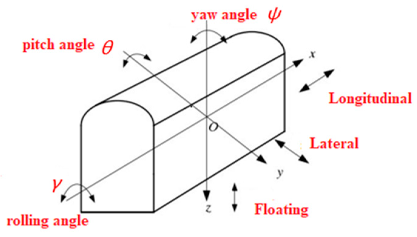
Figure 1. Mining monorail crane.
Energies 16 05969 g001
Figure 2. Interface diagram of monorail crane lifting track.
Energies 16 05969 g002
Figure 3. Key component diagram of a monorail crane. 1—Driver’s cab; 2—Drive device; 3—Tie rod assembly; 4—Main engine; 5—Hydraulic system; 6—Auxiliary vehicle; 7—Electronic control system.
Energies 16 05969 g003
Figure 4. Structural diagram of the driving part of the monorail crane. 1—Brake block; 2—Bearing wheel set; 3—Drive friction wheel; 4—Braking device; 5—Brake arm; 6—Guide wheel; 7—Radial plunger motor and motor seat; 8—Clamping cylinder.
Energies 16 05969 g004
Figure 5. Schematic diagram of vibration degrees of freedom for the monorail crane.
Energies 16 05969 g005
Figure 6. Wheel radial damping model.
Energies 16 05969 g006
Figure 7. Analysis diagram of radial force state on wheel sets.
Energies 16 05969 g007
Figure 8. Dynamic model of the “track + driving unit + driver’s cab” system for a monorail crane.
Energies 16 05969 g008
Figure 9. Contact surface excitation model.
Energies 16 05969 g009
Figure 10. Excitation diagrams of different contact surface levels at a speed of 2 m/s.
Energies 16 05969 g010
Figure 11. Dynamic simulation model of the monorail crane’s motion unit.
Energies 16 05969 g011
Figure 12. Linear vibration curve of the driver’s cab.
Energies 16 05969 g012
Figure 13. Angular vibration curve of the driver’s cabin.
Energies 16 05969 g013
Figure 14. SINS conic error curve using different sub-sample compensation algorithms. (a) the error curve in the X-direction, (b) the error curve in the Y-direction, and (c) the error curve in the Z-direction.
Energies 16 05969 g014
Figure 15. SINS sculling error curve using different sub-sample compensation algorithms. (a) the error curve in the X-direction. (b) the error curve in the Y-direction. (c) the error curve in the Z-direction.
Energies 16 05969 g015aEnergies 16 05969 g015b
Table 1. The corresponding relationship between the degree of freedom parameters of monorail crane.
MovementLongitudinalLateralFloatingRollPitchYaw
Degree of freedom parameters x c y c z c γ c θ c ψ c
Degree of freedomParallel motion along the x-axisParallel motion along the y-axisParallel motion along the z-axisRotation around the x-axisRotation around the y-axisRotation around the z-axis
Table 2. Classification criteria for the unevenness of contact surfaces/10−6m3.
LevelMeanLevelMean
11654096
264616,384
3256765,536
410248262,144
Table 3. Cone error compensation coefficient ( N = 1 6 ).
N k 1 k 2 k 3 k 4 k 5
1-
22/3
327/209/20
4214/10592/10554/105
51375/504650/504525/504250/504
615,797/46207834/46207296/46204558/46202315/4620
Table 4. The statistical properties of the simulation results for coning error.
Subsample NumberStatistical CharacteristicsConing Error (10−3)
X-DirectionY-DirectionZ-Direction
DSMean−4.684−4.4094.133
Std3.5713.3613.151
Max/°−9.932−9.348−8.764
TSMean1.0721.1690.974
Std2.3132.5242.103
Max/°4.3584.7553.962
FSMean0.8390.8400.840
Std0.7150.7150.7151
Max/°1.9931.9931.993
Table 5. The statistical properties of the simulation results for sculling errors.
Subsample NumberStatistical CharacteristicsSculling Error
X-DirectionY-DirectionZ-Direction
DSMean−0.2756−0.248−0.3031
Std0.21010.18910.2311
Max/m/s−0.5843−0.5258−0.6427
TSMean0.09741.0720.0877
Std0.21030.23130.1893
Max/m/s0.39620.43580.3566
FSMean0.06710.10070.0923
Std0.05720.08580.07866
Max/m/s0.15940.23920.2192
Disclaimer/Publisher’s Note: The statements, opinions and data contained in all publications are solely those of the individual author(s) and contributor(s) and not of MDPI and/or the editor(s). MDPI and/or the editor(s) disclaim responsibility for any injury to people or property resulting from any ideas, methods, instructions or products referred to in the content.

