Article

Characterization of Wind Resources of the East Coast of Maranhão, Brazil

by
Felipe M. Pimenta
1,*,
Osvaldo R. Saavedra
2,
Denisson Q. Oliveira
2,
Arcilan T. Assireu
3,
Audálio R. Torres Júnior
2,
Ramon M. de Freitas
4,
Francisco L. Albuquerque Neto
5,
Denivaldo C. P. Lopes
2,
Clóvis B. M. Oliveira
2,
Shigeaki L. de Lima
2,
João C. de Oliveira Neto
6 and
Rafael B. S. Veras
2
1
Centro de Ciências Físicas e Matemáticas, Universidade Federal de Santa Catarina, Campus Trindade, Florianópolis 88040-900, SC, Brazil
2
Instituto de Energia Elétrica, Universidade Federal do Maranhão, Av. dos Portugueses s/n, Bacanga, São Luís 65080-040, MA, Brazil
3
Instituto de Recursos Naturais, Universidade Federal de Itajubá, Av. BPS 1303, Pinheirinho, Itajubá 37500-903, MG, Brazil
4
Camargo Schubert Wind Engineering, Rua Juvenal Galeno, 55, Jardim Social, Curitiba 82520-030, PR, Brazil
5
Applied Meteorology Laboratory, Federal University of Rio de Janeiro, Rio de Janeiro 21941-916, RJ, Brazil
6
Engenharia de Energia, Universidade Federal de Santa Catarina, Campus Araranguá, Rua Pedro João Pereira 150, Mato Alto, Araranguá 88905-120, SC, Brazil
*
Author to whom correspondence should be addressed.
Energies 2023, 16(14), 5555; https://doi.org/10.3390/en16145555
Submission received: 18 June 2023 / Revised: 16 July 2023 / Accepted: 18 July 2023 / Published: 22 July 2023
(This article belongs to the Section A3: Wind, Wave and Tidal Energy)

Abstract

:
The objective of this work is to assess the wind resources of the east coast of Maranhão, Brazil. Wind profilers were combined with micrometeorological towers and atmospheric reanalysis to investigate micro- and mesoscale aspects of wind variability. Field campaigns recorded winds in the dry and wet seasons, under the influence of the Intertropical Convergence Zone. The dry season was characterized by strong winds (8 to 12 m s 1 ) from the northeast. Surface heat fluxes were generally positive (250 to 320 W m 2 ) at midday and negative (−10 to −20 W m 2 ) during the night. Convective profiles predominated near the beach, with strongly stable conditions rarely occurring before sunrise. Further inland, convective to strongly convective profiles occurred during the day, and neutral to strongly stable profiles at night. Wind speeds decreased during the rainy season (4 to 8 m s 1 ), with increasingly easterly and southeasterly components. Cloud cover and precipitation reduced midday heat fluxes (77 W m 2 ). Profiles were convective during midday and stable to strongly stable at night. Terrain roughness increased with distance from the ocean ranging from smooth surfaces ( z o = 0.95 mm) and rough pastures ( z o = 15.33 mm) to crops and bushes ( z o = 52.68 mm), and trees and small buildings ( z o = 246.46 mm) farther inland. Seasonal variations of the mean flow and sea and land breezes produced distinct diurnal patterns of wind speeds. The strongest (weakest) breeze amplitudes were observed in the dry (rainy) period. Daily changes in heat fluxes and fetch over land controlled the characteristics of wind profiles. During sea breezes, winds approached the coast at right angles, resulting in shorter fetches over land that maintained or enhanced oceanic convective conditions. During land breezes, winds blew from the mainland or with acute angles against the coastline, resulting in large fetches with nighttime surface cooling, generating strongly stable profiles. Coastal observations demonstrated that with increasing monopiles from 100 to 130 m it is possible to obtain similar capacity factors of beachfront turbines.

1. Introduction

Wind is by nature a variable phenomenon. It fluctuates at different timescales and its magnitude changes with the geographical location and terrain characteristics [1]. Changes on the timescales of hours to days impact the operation of power networks [2], while fluctuations on the scale of months to years are essential for resource assessment and long-term planning [3,4,5]. Atmospheric stability, turbulent intensity and vertical shear are important characteristics that affect the performance and fatigue loading of turbines [6,7,8,9].
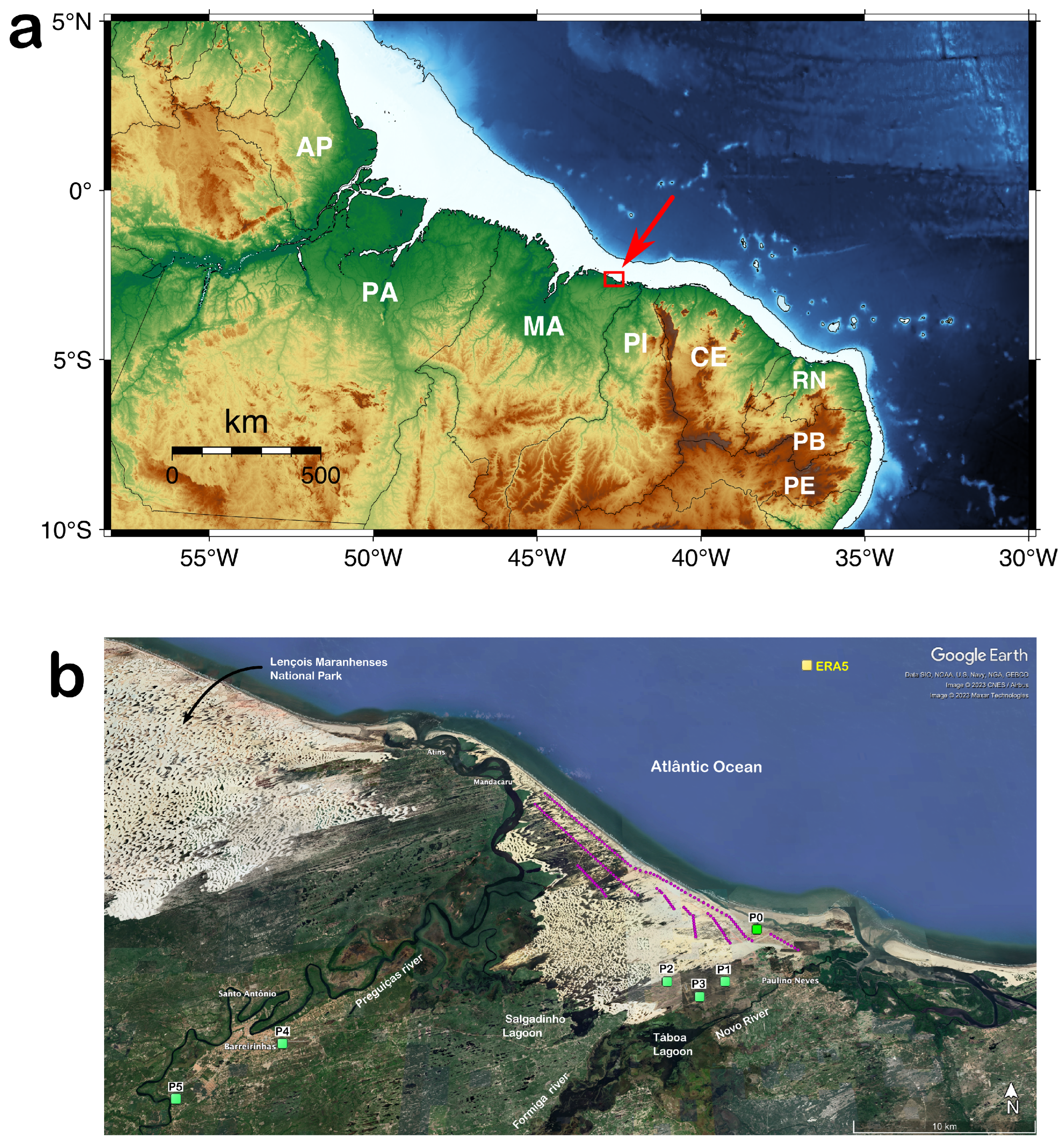
This work investigates the variability and characteristics of winds on the east coast of Maranhão state in northeast Brazil. The study region is located in the far west of an equatorial oceanic area characterized by strong Trade winds that extends for more than 1200 km from 35° W to 44° W [10,11] (Figure 1a). The region also experiences a strong potential for sea–land breezes, including the occurrence of mountain breezes in the neighboring state of Piauí [12]. Satellite imagery demonstrates that sea breeze fronts can travel to considerable distances from the shore, reaching from 40 to 70 km inland [13].
Radiosonde soundings and the analysis of a network of surface meteorological stations suggest that the planetary boundary layer flow is controlled by a southerly large-scale flow at 850 hPa, associated with the Hadley cell, and by a surface flow driven by a mesoscale pressure gradient force [14,15]. The pressure gradient has strong diurnal periodicity and it is induced by land-to-ocean differential heating [15]. Near the coast, the surface large-scale flow develops an easterly component in the form of the Trades [14,15].
Coastal observations demonstrate that the Trades winds blow from the east to northeast at the Alcântara Launch Center (ALC) on the west coast of Maranhão [16,17,18,19]. At Pedra do Sal beach, in the neighboring state of Piauí, winds blow from the northeast to southeast [20,21,22]. Surface satellite observations [10] and upper-level wind at 925 hPa [23] demonstrate that the large-scale flow develops a strong northeast component past the longitude of 40° W.
Southeast Trades are intrinsically related to the dynamics of the Subtropical Anticyclones and the position of the Intertropical Convergence Zone (ITCZ) [24]. The annual cycle in the South Atlantic presents two peaks in both intensity and size for the South Atlantic Subtropical High (SASH) pressure center [25,26]. In the austral summer (December–January–February), the center is strong, but farthest poleward and positioned in the center of the basin. During the austral winter (June–July–August), SASH is closest to the equator and positioned in the western part of the Atlantic.
ITCZ is the ascending branch of the Hadley circulation, characterized as a belt of low pressure and the confluence of the Trade winds. The area is commonly identified as a region of strong cloud cover, convective precipitation and calm winds. ITCZ migrates seasonally from its northernmost location (8° N) in September–October–November to its southernmost position (2° S) in February–March–April [23,27,28]. Trade wind strength demonstrates peak intensities in September–October–November and lower speeds in February–March– April [10,11], in line with the ITCZ position, but with a delayed response to the SASH winter migration and intensification.
The most frequent occurrences and the largest amplitudes of sea–land breezes are observed in the dry season (August–November) when the differences of air temperatures over land and the ocean are the highest [12,15]. Nearshore observations at the coast of Piauí demonstrate marked diurnal variabilities with peak wind speeds in the morning (6 to 9 h local time) and the lowest speeds at noon [29], while on the west coast of Maranhão, the higher peak speeds occur during the morning (6 to 12 h local time) in the dry season and late in the afternoon during the wet season [16,17,18,19].
Fewer field observations have been performed on the east coast of Maranhão, where the Delta Maranhão Wind Complex is located (Figure 1b). Tall tower measurements were previously employed in the development of a forecast hybrid model but without a description of the diurnal or spatial characteristics of winds [30].
The Delta Wind Complex has 172 wind turbines which add up to the total installed capacity of 426 MW. Maranhão’s wind resources remain underexplored compared to other northeast states, although there are vast areas available for exploration in coastal and offshore areas (Figure 1b).
Figure 1. (a) Brazil equatorial margin. The study region is indicated by a red square with an arrow. Within the equatorial coast, Rio Grande do Norte (RN) has the largest installed wind capacity: 6855 MW; followed by Piauí (PI): 3428 MW; Ceará (CE): 2568 MW; Pernambuco (PE): 1025 MW; Paraíba (PB): 672 MW and Maranhão (MA): 426 MW [31]. (b) Eastern coast of Maranhão, Brazil. Barreirinhas and Paulino Neves counties are indicated. EOSOLAR study region is located in a region known as “little Lençóis”, east of the Preguiças River. Observation points are indicated by green squares, numbered from P0 to P5. Point P0 is located 1.5 km from the beach. Point P4 and point P5 are located 26 and 32 km, respectively, from P1. Turbine locations are identified by magenta dots. ERA5 refers to the grid point location (2.5° S, 42.5° W) derived from the atmospheric reanalysis, which is 26 km from P1. Stations’ geographical coordinates are P0 (2.694107° S, 42.554807° W), P1 (2.724877° S, 42.575182° W), P2 (2.725162° S, 42.606507° W), P3 (2.733535° S, 42.589530° W), P4 (2.759033° S, 42.807133° W) and P5 (2.787355° S, 42.855720° W). Image source: Google Earth.
Energies 16 05555 g001
This article explores a series of field campaigns conducted as part of Project EOSOLAR, carried out for the assessment of wind and solar resources of Maranhão [32]. Two micrometeorological towers, a SODAR (Sound Detection and Ranging) and a LIDAR (Light Detection and Ranging), recorded data from 14 September 2021 to 27 July 2022, between the municipalities of Barreirinhas and Paulino Neves. Observational stations covered terrains near the beach, regions with grass vegetation in the dune fields, as well as points far from the coast and under urban influence (Figure 1b).
Field campaigns monitored winds during the dry, as well as in the rainy season. The experimental setup was new, as it employed two vertical wind profilers in tandem with two micrometeorological towers. That allowed the time monitoring of a fixed location and exploration of spatial changes due to terrain characteristics. Instrument validation and preliminary results of EOSOLAR were reported in Assireu et al. (2022) [32] and Torres et al. (2022) [33]. Wind maps derived from numerical atmospheric downscaling are available in the form of the web-based application Plataforma Interativa de Energias Renováveis (PIER, https://eosolar.equatorialenergia.com.br, accessed on 28 February 2023).
The objective of this article is to explore the breadth of the micrometeorological and wind profiler dataset, providing a comprehensive description of the regional atmospheric circulation, diurnal variability and the effects of terrain roughness and heat fluxes on the vertical structure and distribution of wind resources. The interaction of sea–land breezes with the Trades will be investigated as it affects wind direction and the diurnal variability of wind speed and shear.
Previous studies have examined the influence of atmospheric stability and wind direction on wind resource characteristics. Barthelmie et al. (1999) evaluated the effects of surface roughness, stability changes and wind direction for land and sea towers near the Vindeby offshore wind farm in Denmark [34]. Sathe et al. (2011) studied a dataset of two offshore towers in the North Sea and evaluated atmospheric stability for winds blowing from the ocean sector [35]. The effects of stability on wind shear, turbulence and turbine performance were studied by Wharton and Lundquist (2012a,b) for an onshore wind farm in western North America [7,36]. Archer et al. (2016) studied long-term observations of an ocean tower and described daily to seasonal changes in atmospheric stability off the northeastern United States [37].
Ocean winds have typically lower surface roughness, higher wind speeds and lower turbulence compared to land sites [22,38,39]. On northeast Brazil, in particular, sea winds are expected to present neutral to unstable atmospheric conditions, as demonstrated by radiosonde [15], tower [17,22] and climatological data [10]. Therefore, turbines very close to the shoreline are subject to steadier, stronger and less vertically sheared wind profiles [22]. For turbines located further inland, winds are prone to interact with different topographical and surface roughness elements, also adapting to changes in heat fluxes. The impact of these changes over the vertical profile will be dependent on the distance traveled by the wind over land. The angle of winds relative to the coastline might have a significant impact on the development of internal boundary layers [40].
The hypothesis of this article is that there are substantial resources in the coastal region adjacent to the Delta wind complex, as winds blow mostly from the offshore sector over gentle slopes with low roughness terrains that are subject to convective conditions. Since most onshore and offshore wind turbines are deployed within a few kilometers of the coastline, the EOSOLAR campaigns should overcome the present lack of high-resolution spatial information, providing a quality dataset for wind assessments and model validations.
The rest of this article is organized into three sections. Section two presents the Material and Methods, with a description of the meteorological instrumentation, field campaigns, atmospheric reanalysis and the background theory used for atmospheric stability and wind profile characterization. Results are presented in the third section. Descriptions of the meteorological conditions during the field campaigns are explored, comparing reanalysis fields with observations. Time series of wind speeds, statistical descriptions, mean vertical profiles and diurnal hodographs are presented. The micrometeorological analysis presents estimations of the terrain roughness, buoyancy heat fluxes, Obukhov length and the shear exponent parameter. Resource spatial and temporal variability are evaluated as a function of time, height and station position. The final section presents a summary and the main conclusions of this work.

2. Materials and Methods

2.1. Meteorological Instrumentation

Wind profile observations were were made with a LIDAR (Light Detection and Ranging) and a SODAR (Sound Detection and Ranging), while micrometeorological variables were measured with two instrumented towers.
The LIDAR employed was a Windcube V2 from Leosphere/Vaisala. The equipment computes the Doppler shift from backscattered infrared light reflected by aerosols carried by the wind. Based on the radial velocities of five different laser beams, the equipment evaluates the wind speed and direction for selected heights with 10 m vertical resolution [41]. The SODAR was a MFAS from Scintec. Its operation is based on the reflection of acoustic pulses due to temperature inhomogeneities present in the air, with subsequent Doppler analysis. MFAS operates in multi-frequency mode with pulse frequencies in the range of 1650 to 2750 Hz, which significantly increases its signal-to-noise ratio for a vertical resolution of 10 m [42].
These two instruments provided averaged profiles of wind speeds and directions every 10 min. SODAR heights selected for analysis were 40 to 260 m every 10 m in a total of N = 23 observations. LIDAR measured heights from 40 to 200 m every 10 m and heights from 220 to 260 m every 20 m in a total of N = 20 observations (Table 1).
Prior to their deployment in the study region, wind profilers collected data for 20 days at the Electrical Energy Institute of the Federal University of Maranhão (IEE/UFMA). Correlation for horizontal wind components was higher than 0.9 and values for the vertical velocity varied between 0.7 and 0.85 (see Torres Júnior et al., 2022 [33]).
Micrometeorological towers provided near-surface winds, atmospheric pressure, temperature, relative humidity and precipitation. Instruments were mounted over two self-supporting tipper towers of 10 m height, mounted over a road trailer. Towers were tensioned by six sets of steel cables, attached to three horizontal legs attached to the trailer base.
Pluviometers were installed at 1.5 m, barometers and thermohygrometers at 3 m height. Gill WindSonic 75 2D anemometers were installed in both towers at 5, 7.5 and 10 m. RM Young 81,000 ultrasonic 3D anemometers were installed at 3.5 m above the ground, providing three wind speed components and sonic temperature at the sampling rate of 20 Hz. High-frequency data were subject to screening, through plausibility thresholds and the MAD-based spike detection of Mauder et al. (2013) [43]. A description of field equipment and auxiliary instruments are listed in Table 1.
The tower’s instruments were also compared prior to field deployment. Biases and regression intercepts were very small for micrometeorology sensors and derived turbulent quantities [32]. Instruments’ configuration and validation and a description of the power and communication systems are provided in Assireu et al. (2022) [32].

2.2. Study Region and Field Campaigns

Field surveys were conducted on the east coast of Maranhão state around 2°42 S of latitude and 42°33 W longitude [32]. The region is located southeast of Lençóis Maranhenses National Park and between Barreirinhas and Paulino Neves counties (Figure 1b).
The study area neighbors the Delta Maranhão Wind Complex, which is composed of 172 General Electric GE116 wind turbines of 2.0 to 2.7 MW. Its turbine locations are identified with magenta dots in Figure 1b. Their rotor diameters are 116 m and hub heights vary between 80 and 90 m for a total installed capacity of 426 MW [44].
EOSOLAR observational stations are identified by green squares in Figure 1b, numbered from P0 to P5. They cover the region close to the beach, areas in the coastal plain considered for further development and regions farther away from the coast for modeling purposes and regional resource assessments. Winds blow preferably from ENE so that these stations are relatively aligned with the predominant direction.
Point P0 was located 1.5 km from the ocean. Points P1, P2 and P3 were 5.6 to 7.8 km from the beach in a region of similar terrain, characterized by dune-ridge morphologies and dune slacks with fixed grass (see Figure 2 of Assireu et al., 2022 [32]). Station P4 was located at Barreirinhas airport and 26 km from station P1. P4 was in a terrain composed of sands, with low-lying areas. Station P5 was positioned southwest of Barreirinhas in a vegetated area with small bushes and 500 m east of Preguíças River. P5 was located 32 km from point P1 (Figure 1b).
The surveying period covered 317 days from 14 September 2021 to 27 July 2022 divided into six field campaigns (FC), hereafter referred as FC1 to FC6 (Table 2). Environmental data were always obtained simultaneously at two different stations. LIDAR and SODAR were accompanied by a micrometeorological tower at all times. Equipment items’ positions during each field campaign are listed in Table 2.
The first field campaign FC1 was conducted from 14 September to 8 November 2021 for a total of 55 days. The SODAR-microtower set was installed at P0, while the LIDAR-microtower was positioned at P1 (Table 2). P0 was initially planned as a fixed reference station for continuous monitoring of wind profiles with the SODAR. Due to the poor return signal at this location, the SODAR monitoring station was moved to point P1 during FC2. The SODAR-microtower set remained installed on P1 for the remaining field campaigns FC2 to FC6. The LIDAR-microtower set was installed in different positions during campaigns: P1 on FC1, P0 on FC2, P2 on FC3 and P3 on FC4, P4 on FC5 and P5 on FC6 (Table 2). Although the total period of data collection was less than a year, it was possible to record the most important changes between the dry and rainy seasons.
Station positions were selected in such a way as to minimize the interference from turbine wakes. Points P1 to P3 were between 2.7 and 8.4 km from Delta Complex wind turbines (Figure 1b). For turbines aligned along the preferable wind direction (40 to 80° N), distances were greater than 4 km. P1 was positioned 2.7 km from the third row of turbines but with turbines placed at an angle of 11° N, a rare direction for the occurrence of winds. P1 to P3 were distant more than 10 turbine diameters from any wind turbine. Point P0 was positioned windward of any turbine located in the front row of the wind park, except for a group of 9 turbines located at the western limit of Delta complex (see Figure 1). These turbines were 0.8 to 2.7 km from P0 but oriented at 107° N to 118° N, an infrequent direction for winds observed during FC1 and FC2 campaigns.

2.3. ERA5 Atmospheric Reanalysis

Reanalysis combines the use of atmospheric forecasting models and sophisticated data-assimilating systems in order to provide consistent gap-free maps of essential climate variables. ERA5 is the fifth generation of global atmospheric reanalysis generated by the European Centre for Medium-Range Weather Forecasts (ECMWF) [45,46]. In this study, ERA5 wind and precipitation data with hourly time resolution are used for a description of the meteorological field conditions during the EOSOLAR campaigns. A climatological time series (1979–2021) with monthly time resolution was selected for a grid point located at 42.5° W, 2.5° S and the seasonal analysis of winds and precipitation. ERA5 has been previously validated with towers [47], LIDAR wind profilers [48] and different locations worldwide [49]. ERA5 was validated regionally with observations of the Alcântara Launch Center tower and EOSOLAR datasets [5,18,50].

2.4. Wind Profile and Atmospheric Stability

The Monin–Obukhov similarity theory provides a semi-empirical framework to investigate boundary layer processes under momentum and buoyancy exchanges [40,51,52]. According to this theory, the wind speed U dependence on the height z above the surface can be modeled by:
U ( z ) = u κ l n z z o ψ z L .
Here u is the friction velocity, κ = 0.4 is the von Karman constant and z o is the aerodynamic roughness parameter. ψ represents a set of empirically derived stability functions dependent on the Obukhov length scale (L) and the height z. Friction velocity can be directly computed from tower micrometeorological observations [52]:
u = u w ¯ 2 + v w ¯ 2 1 / 4 ,
where u = u u ¯ , v = v v ¯ and w = w w ¯ represent the turbulent velocity components in the x, y and z cartesian directions, respectively. In these expressions, u, v and w represent the observed velocity components and the overbar ( ) ¯ represents a time average. Before the computation of turbulent quantities, velocity components were subject to coordinate rotation. The employed procedure is referred to as the double rotation (or tilt correction) method, which involves a first rotation around the z-axis, aligning u with the mean wind and a second rotation around the y axis, until the mean vertical wind speed disappears [32,53]. With these rotations, the anemometer coordinate system becomes aligned with the streamlines. Over flat terrain, these rotations correct errors in the vertical orientation of anemometers [52].
Winds were recorded at 20 Hz with 3D ultrasonic anemometers installed at 3.5 m height in both micrometeorological towers. The averaging period considered was 10 min for all micrometeorological analyses (Table 1). The Obukhov length was evaluated from:
L = u 3 κ g T v w T s ¯ .
Here g = 9.8 m s 2 and T v = T(1 + 0.6087 q a ) is the average virtual temperature, with T as the absolute temperature and q a as the specific humidity. ( w T s ¯ ) represents the covariance of vertical velocity perturbation w with the high frequency sonic temperature fluctuation T s . T s is nearly identical to the virtual temperature so that the heat flux estimated from observations is equivalent to the buoyancy heat flux (W m 2 ) [37,52,54]:
Q h b = ρ c p w T s ¯ .
Here c p = 1004.67 (J kg 1 K 1 ) is the specific heat and ρ is the moist air mean density (kg m 3 ) [40,52]. Positive heat fluxes ( w T s ¯ > 0 ) indicate the surface heating up the atmosphere. Conversely, negative fluxes ( w T s ¯ < 0 ) indicate the ground cooling down the surface air.
A physical interpretation of the Obukhov length is that its magnitude | L | represents the thickness of the dynamical sublayer where shear friction dominates over buoyancy effects. Hence, shear effects dominate for heights z | L | and buoyancy effects dominate for z | L | [40,51,55]. The sign of L is determined by the sign of the heat flux. L is positive in situations where the surface cools the air and negative when the surface heats the air. L is large in a neutral atmosphere because buoyancy fluxes are near zero and frictional effects predominate. For strong convective or strong stable conditions, L is typically small, indicating that friction is only important very close to the surface [37].
With the Obukhov scale at hand, one can estimate the stability function ψ of Equation (1) from empirical relationships [56,57,58]. See reference [10] for a summary of functions used for unstable conditions, slightly stable cases and very stable conditions. The roughness length z o can be then computed with u , ψ and the wind speed U r measured at the reference level z r = 10 m [59]:
z o = z r e x p κ U r / u + ψ .
Friction velocity and the roughness length will be presented in Section 3.3.1. Heat fluxes will be described in Section 3.3.2. Obukhov length will be used to characterize the atmosphere stability in Section 3.3.3.

2.5. Wind Shear Exponent

The wind shear can be quantified by the so-called power-law equation [6,60]:
U ( z ) = U r z z r α .
Here U is the wind speed (m s 1 ) at the height z (m), U r is the velocity measured at a reference height z r and α is the shear exponent. This exponent is not a direct measure of stability, but it fairly describes the degree of vertical shear associated with stability [36]. Its analysis facilitates the comparison of wind profiles from different stations or field campaigns. When combined with the analysis derived from the Obukhov length, the shear exponent helps to understand the underlying local and regional processes that control the vertical structure of the winds.
A least squares method, proposed by Archer and Jacobson (2003) [61], was applied to the LIDAR and SODAR data, in order to estimate the dimensionless shear from wind observations at different levels:
α = i = 1 N ln U i U r ln z i z r i = 1 N ln z i z r 2 .
Here, the index i represents the different measuring heights and N is the total number of vertical observations. U r was set as the reference speed for the height of z r = 110 m. Shear exponent estimates were estimated from 10 min average wind speeds, considering only profiles with N > 10 observations, U r > 3 m s 1 and root mean squared errors (RMSE) below 1 m s 1 . The results of shear exponent analysis are presented in Section 3.3.4.

2.6. Weibull Probability Distribution

A compact form of characterizing wind speeds is achieved by the use of probability distribution functions. Here, we employed the two-parameter Weibull distribution
p ( U ) = k c U c k 1 e x p U c k ,
where k is the shape and c the scale parameter [6]. Increasing the scale c parameter and keeping k fixed generally have the effect of spreading and shifting the probability distribution towards larger speeds. On the other hand, the increase in the shape k parameter while holding c constant tends to squeeze the distribution, so that p ( U ) has sharper peaks and less wind speed variations. The Maximum Likelihood Method (MLM) was employed to estimate the k and c Weibull parameters for from the LIDAR and SODAR observations at 100 m height [62,63].

3. Results

3.1. Meteorological Conditions

3.1.1. Reanalysis vs. Observations

Figure 2a compares the wind speed derived from the ERA5 product with observations from station P1. Observations refer to a series composed of LIDAR and SODAR winds at the height of 100 m. ERA5 series refers to an offshore grid point located 26 km from P1 at coordinates 42.5° W and 2.5° S (Figure 1b). The graph covers the period from September 2021 to July 2022 (Figure 2a). Winds demonstrate a clear transition of regimes captured both by observations and the reanalysis product. High wind magnitudes on the order of 8 to 12 m s 1 were observed in the spring of 2021 during FC1 and FC2. Winds then transitioned to lower magnitudes around 7 m s 1 during the field campaign FC3 and reduced even further in early March, with speeds around 4 to 8 m s 1 during FC4. Winds remained within these speeds from mid-March to early June (FC4 to FC5) and started to recover from the end of FC5 to FC6.
The correspondence between the observed data and the reanalysis product was remarkable. ERA5 captured relatively well the fluctuation of winds. Wind series correlated at R = 0.68 for 1 h time resolution, with root mean squared errors of RMSE = 1.85 m s 1 . These numbers improved to R = 0.77 at 6-hourly resolution and peaked at R = 0.88 for 24-hourly averages (Table 3). RMSE was 0.77 m s 1 for 6-hourly resolution and 0.94 m s 1 for 24 h averages. Bias = −0.09 regardless of the time resolution, so ERA5 slightly underestimated wind speeds (Table 3).

3.1.2. Winds and Precipitation Fields

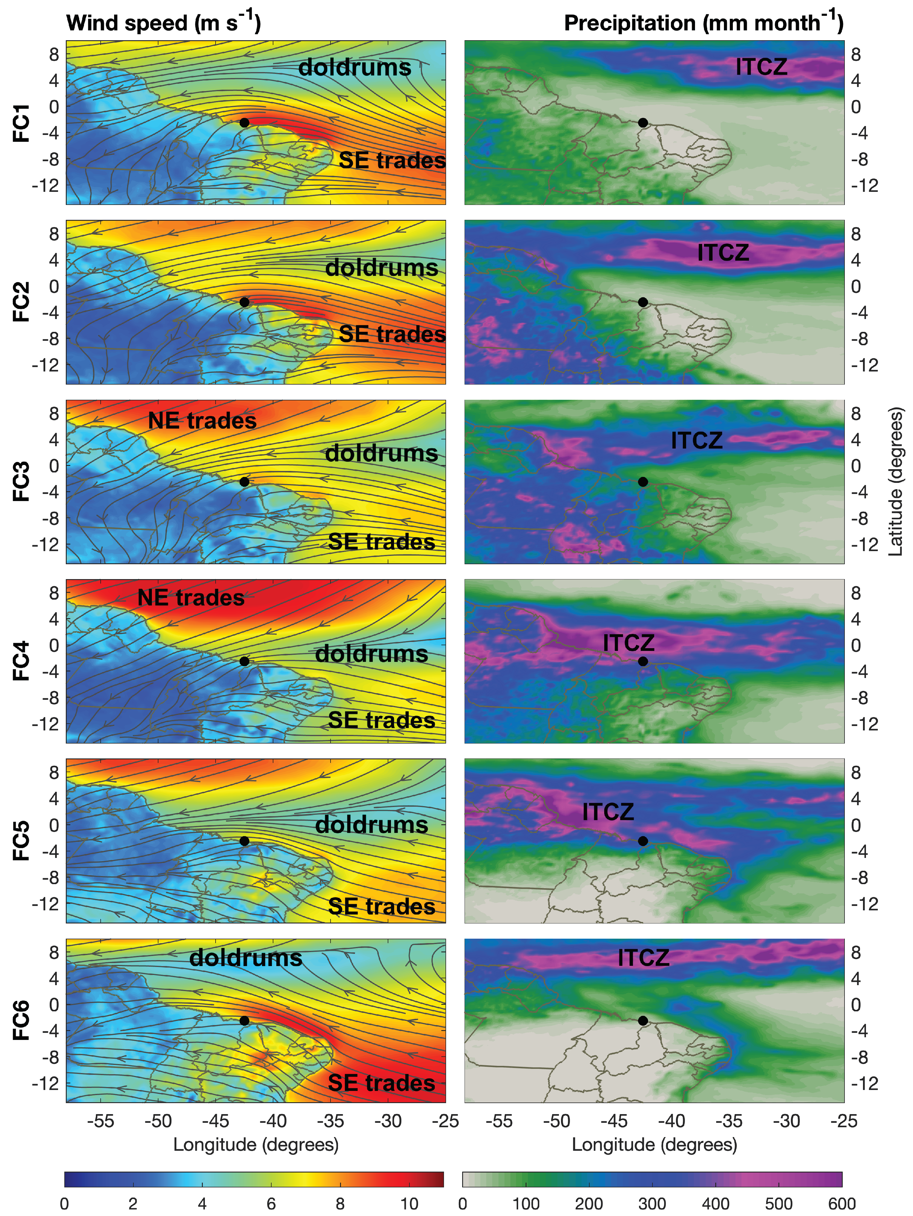
Figure 3 illustrates the wind fields and precipitation obtained from ERA5 during EOSOLAR surveys. Field campaigns are displayed in rows from top (FC1) to bottom (FC6). The left panels illustrate the 100 m mean wind fields and the right panels the accumulated precipitation for the same period. A black dot identifies the study region in these maps.
Winds were intensified along the coasts from the state of Rio Grande do Norte to Maranhão during field campaigns FC1 and FC2 (September to December 2021), with a clear influence of the SE Trades during the spring (Figure 3). The climate was dry on the eastern Maranhão coast. The accumulated precipitation inferred from micrometeorological towers was 47.7 mm for FC1 and ∼160 mm for FC2 (Table 2). The ITCZ was displaced north of the study region, organized in the form of a zonal band positioned between 4° and 8° N. The “doldrums”, a region characterized by low-level wind convergences and null winds, was displaced north of the equator and far from Maranhão’s east coast (Figure 3).
During field campaign FC3 (December 2021–January 2022), the ITCZ started migrating towards the southwest, causing strong precipitation over the coasts of Amapá and Amazonas. Precipitation was observed over the study region, totaling 170 mm during FC3 (Table 2). Winds reduced their strength due to the south displacement of the doldrums, reaching speeds around 7 m s 1 (Figure 2a and Figure 3).
The ITCZ continued its southward migration during the FC4 (end of January to April 2022) and FC5 (April to June 2022), finally reaching the latitude of 4° S, causing intense precipitation over the east coast of Maranhão. A total of 728 mm of rain for FC4 and 573 mm for FC5 were recorded by the micrometeorological towers (Table 2). This corresponded to the period of more variable and weaker wind speeds in the study region. Southeast Trades remained slightly faster in a narrow coastal strip from Rio Grande do Norte to Piauí, the neighboring state, but without noticeable impact for the east coast of Maranhão (Figure 3).
ITCZ resumed its migration to the north during FC6 (June to July 2022), with the migration of the doldrums northward and a clear strengthening of the SE Trades on the northeast coast of Brazil. Offshore winds displayed on the map during FC6 had strong wind speeds but were blowing predominantly from the southeast and east near the study region. This contrasts with FC1 and FC2 where winds presented stronger northeasterly orientations, blowing predominantly from the ocean (Figure 3). Directional statistics of the wind profilers and its impact upon coastal resource magnitudes will be, respectively, explored in Section 3.2.2 and Section 3.4.

3.1.3. Climatology of Winds and Precipitation

It is worth situating EOSOLAR measurements within a climatological context. Boxplots of Figure 2b,c illustrate ERA5 monthly climatologies (1979–2021) for wind speeds and precipitation based on ERA5 offshore observations near the study area (see Figure 1b). Wind observations from station P1 are plotted as blue bullets (SODAR) and triangles (LIDAR) in Figure 2b. Precipitation derived from micrometeorological towers are shown as green bullets in Figure 2c.
Wind climatology illustrated a high amplitude seasonal signal for Maranhão’s east coast. Strong winds and low variability are expected for spring (September to November) and weak winds with variable speeds tend to occur during the fall (March to May). Transitional months (May to July) tend to be highly variable and present the most extreme data points. Comparing the climatology, EOSOLAR wind observations were near or below the median from March to November and above the median in December 2021 and February 2022.
Additionally, a yearly signal that is out of phase with wind variability may be seen in the precipitation climatology. Strong precipitation is expected for the fall (March to May) when the ITCZ reaches its lowest latitude, while dry weather is expected during the spring (September to November) when the ITCZ migrate northwards. Precipitation can vary significantly during the rainy season, while much less variability is anticipated during the drought period, as indicated by the height of box plots.
Compared to observations, the climatology suggests that precipitation was near the median for January, June 2022 and October 2021. Precipitation was above 400 mm month 1 and higher than the 75th percentile for March and May 2022, but near 100 mm month 1 and well below the 25th percentile for April 2022. Microtower precipitation time series reveal that rain was unequally distributed in time, with high precipitation rates at the end of March and beginning of May for Paulino Neves and Barreirinhas region. The accumulated precipitation, however, was 728 mm during FC4 (February to May) and 573 mm for FC5 (May to June) (Table 2).
Analysis of surrounding meteorological stations from the National Institute of Meteorology (https://mapas.inmet.gov.br, accessed on 27 March 2023) for the month of April 2022 indicates 514 and 529 mm month 1 of precipitation, respectively, for Chapadinha and Vargem Grande counties, which are located near 150 km southwest of Paulino Neves. Met station from Araioses station, 76 km east of the study region, indicated 281 mm month 1 of rain. This suggests that east Maranhão experiences uneven precipitation distribution during the rainy season.

3.2. Wind Variability and Statistics

Field campaigns were planned to assess the spatial and temporal variability of wind resources in the coastal region between Paulino Neves and Barreirinhas. Table 2 lists the periods of each field campaign, along with the LIDAR and SODAR positions, while Figure 1b illustrates station positions on a map. The following subsections will explore the results in terms of the time series of winds, their speed and directional statistics, vertical profiles and diurnal variability.

3.2.1. Time Series at Hub Height

An important objective of EOSOLAR was the investigation of the spatial variability of wind resources, through simultaneous measurements performed at different prospective locations. SODAR was used as a control monitoring station, while LIDAR was reinstalled over different terrains.
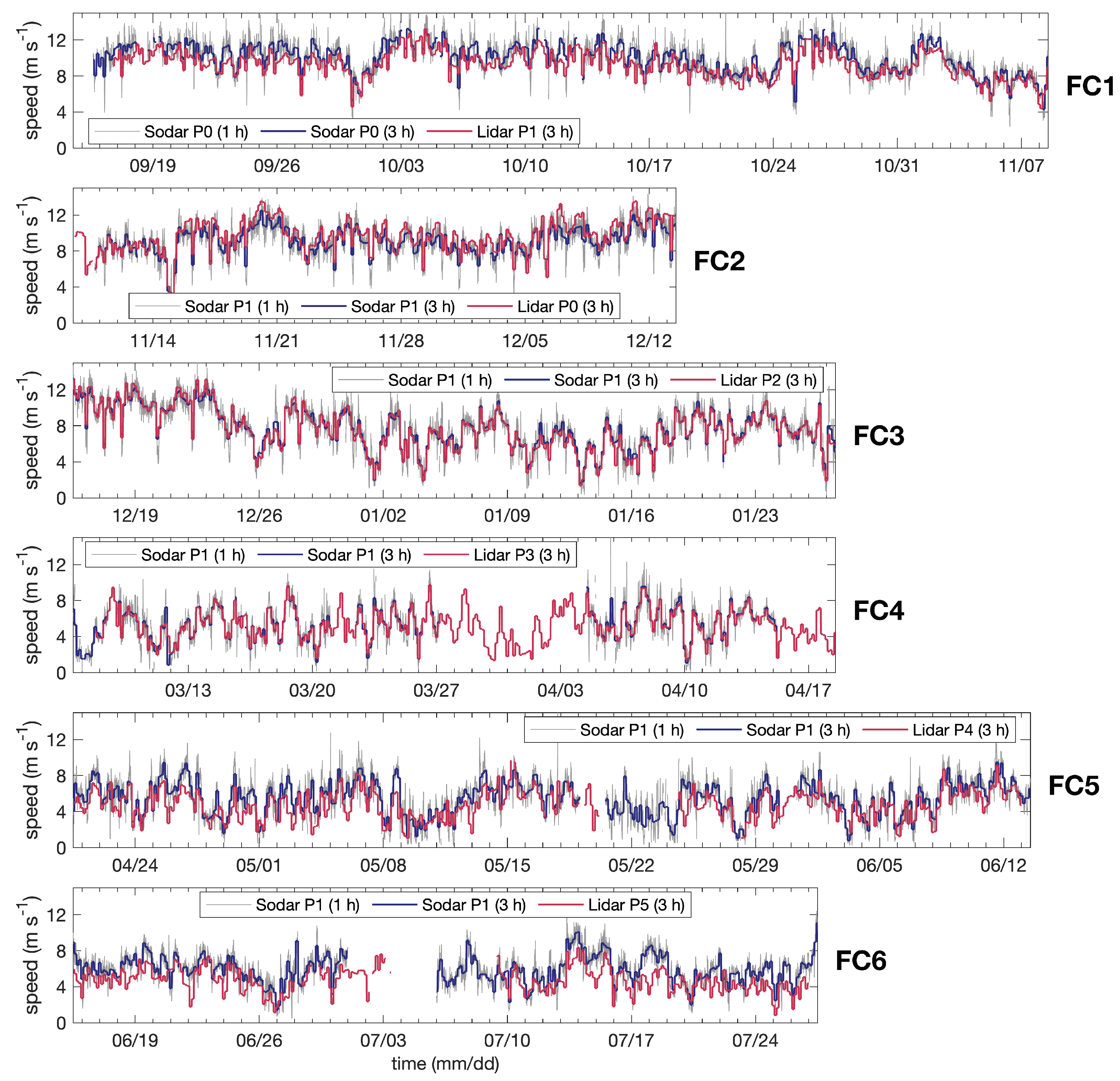
Figure 4 illustrates the time series of wind speeds measured by these wind profilers for all field campaigns. The gray line represents the SODAR data at a 10 min time resolution. The thick blue and thick red lines, respectively, represent the SODAR and LIDAR at 3 h time resolution to facilitate comparisons. All series refer to winds at the height of 100 m above the surface, which is near the hub height of present turbines.
The first campaign (FC1) was conducted from September to November 2021. The SODAR was installed at P0, nearly 1.5 km from the ocean, while the LIDAR was installed at point P1, nearly 5.3 km from the beach. As mentioned in the previous section, FC1 was characterized by a dry climate with strong Trade winds blowing from east to northeast over Maranhão. This fact was confirmed by LIDAR and SODAR observations, which demonstrated strong and sustained winds, with wind speeds from 8 to 12 m s 1 . Both stations presented similar daily-to-weekly variabilities, with peak speeds in October and early November of 2021. In some situations, however, winds at P0 were up to 1 m s 1 stronger than winds at P1 (Figure 4). In statistical terms, the average speed at 100 m height was 9.28 m s 1 for P1 versus 9.76 m s 1 for P0, a difference of 0.48 m s 1 (Table 4). Winds never reached zero magnitude and the minimum speeds were on the order of 2.4 m s 1 . The time series on the background illustrated ramps could reach 4 m s 1 . Ramps tended to be short-lived, as the 3-hourly averaged series remove many of their occurrences. Standard deviation of wind speed was 1.67 m s 1 at P1 versus 1.84 m s 1 at P0 (Table 4).
The FC2 field campaign was shorter than FC1 and conducted from mid-November to mid-December 2021. During this campaign, the SODAR was transferred to point P1 due to the poor signal return at P0 (Table 4). LIDAR recorded winds at the coastal point P0. This was still a period of very intense winds and the large correspondence of wind series was maintained, although P0 winds were still higher than P1. Average speed was 9.07 m s 1 for P1 versus 9.63 m s 1 for P0, a difference of 0.56 m s 1 (Table 4). Minimum values of 0.6 m s 1 were recorded in mid-November 2021, while maximum values of 15.2 m s 1 were observed at P0 and 14.3 m s 1 at P1. Standard deviation was 1.78 m s 1 at P1 and 2.01 m s 1 at P0 (Table 4).
The third field campaign FC3 was conducted from mid-December 2021 to January 2022 (Figure 4). SODAR continued its measurements at point P1 while the LIDAR was reinstalled at point P2 which was located 3.4 km westward of P1. This campaign marked the spring to summer transition, with a progressive reduction in winds and increasing precipitation, as discussed in the previous section. The correspondence of wind speeds was remarkable between stations. Average wind speeds were 7.75 m s 1 for P1 and 7.61 m s 1 for P2, a difference of 0.14 m s 1 . On many occasions, winds dropped to speeds below 2 m s 1 in January 2022 (Figure 4).
During FC4 the SODAR remained installed at P1, while the LIDAR was moved to point P3, located 1.8 km southwest of point P1 (Figure 1b). The campaign was conducted from the end of January to mid-April 2022, a period characterized by heavy rainfall due to the ITCZ influence (Table 2). Winds were reduced and the average velocities reached 5.21 m s 1 for P3 compared to 5.41 m s 1 for P1, a difference of 0.20 m s 1 (Table 4). Maximum speeds of 8 m s 1 were observed and near null speeds were more common, as illustrated by the time series of P3 (Figure 4).
During field campaign FC5, the SODAR continued its monitoring at P1, while the LIDAR was reinstalled on point P4 near Barreirinhas’ airport and 26 km distant from point P1 (Figure 1b). The campaign was conducted from April to June 2022, a period also characterized by heavy rainfall and low wind speeds. Average wind speeds were 4.77 m s 1 for P4 versus 5.47 m s 1 for P1, a difference of 0.7 m s 1 (Table 4).
FC6 was conducted from June to July 2022. The LIDAR was moved to point P5, westward of P4 and nearly 32 km from the SODAR at station P1. Point P5 was located in an urban area and eastward from the Preguiças River. The correspondence of winds at these locations is still noticeable, although differences can reach 3 m s 1 in some situations, such as 18 July 2022. Average wind speeds were 4.68 m s 1 at P5 against 5.91 m s 1 at P1, a difference of 1.23 m s 1 (Table 4).
In summary, time series illustrates that the most substantial changes in wind speeds occur across field campaigns. For example, the strongest mean winds for monitoring station P1 were observed in the dry period, with 9.28 m s 1 , compared to 5.41 m s 1 during the wet period, a difference of 3.87 m s 1 or a gain of 71%. These fluctuations are likely influenced by the migration of the ITCZ and Trade winds. Moreover, spatial discrepancies range from 0.14 m s 1 between P2 and P1 for a gain of 1.8%, 0.20 m s 1 for P3 and P1 (gain of 3.8%), 0.56 m s 1 for P1 and P0 (gain of 6.2% during FC2), 0.70 m s 1 for P4 and P1 (gain of 14.67 %) and 1.23 m s 1 for P1 and P5 (26%). These variations can be attributed to the roughness of the terrain surface, as will be explored in further detail.

3.2.2. Speed and Directional Statistics

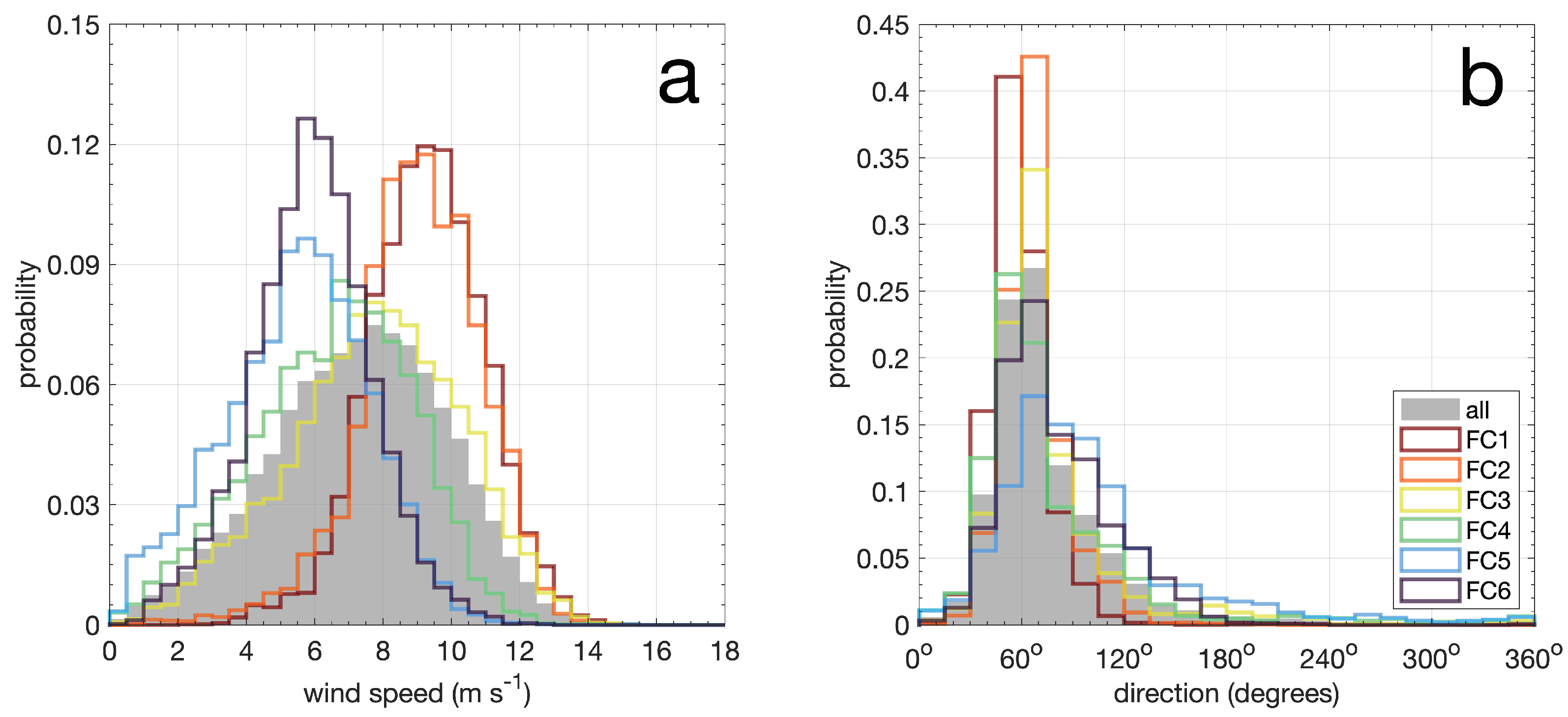
Statistical distributions of wind speed are shown in Figure 5a. The graph depicts probability distributions for winds at the height of 100 m measured at point P1, the station with the longest record. Colored lines represent the distributions for each field campaign, varying from FC1 (red) to FC6 (purple). The gray shading represents a distribution composed of all observations. Table 5 lists Weibull probability parameters, distribution skewness as well as percentages of time that winds remain below or above specific speeds.
A clear distinction in wind regimes is observed. The first two campaigns FC1 and FC2 presented distributions displaced to the right, characterized by modal speeds between 9 and 9.5 m s 1 . The occurrence of wind speeds U above 10 m s 1 occurred more than 31% of the time in these campaigns (Table 5). On the other hand, FC5 and FC6 distributions were shifted to the left, with modal speeds between 5.5 and 6 m s 1 . Winds were greater than 10 m s 1 less than 1.22% during these campaigns (Table 5). FC1 and FC2 skewness were −0.19 and −0.59, respectively, characterizing distributions with tails displaced to the left, toward weaker winds. FC5 and FC6 presented positive 1.27 and near zero −0.03 skewness, respectively. FC3 and FC4 presented modal distributions between 7.5 and 8 m s 1 and 6.5 and 7 m s 1 , respectively. Skewness was −0.23 for FC3 and 0.04 for FC4.
Periods of turbine inactivity, typically characterized by turbine cut-in speeds U < 3 m s 1 , correspond to 0.03% for FC1, increasing to 13.59% for FC5 and reaching 5.30% on FC6 (Table 5). Periods above the turbine cut-out speed (U> 25 m s 1 ) were nearly absent.
Table 5 lists the Weibull parameters fitted to the field campaign observations. The scale parameter is c = 9.97 for FC1 and progressively decays to c = 6.14 on FC5. FC6 demonstrated a slight increase, with c = 6.54. The shape parameter is k = 6.21 for FC1 and progressively decays to k = 2.46 on FC5. FC6 recovers the shape to k = 3.75.
Figure 5b presents the wind direction histograms. The direction follows the meteorological convention, indicating the direction from which the wind blows. Angles are represented in degrees, clockwise from the geographical north. Graph illustrates unimodal distributions, with modal directions from the east-northeast (ENE), specifically between 45° and 60° N for FC1 and FC4 and 60° and 75° N for FC2, FC3, FC5 and FC6. Results also demonstrate more narrow distributions for FC1 and FC2 and longer tails towards the east and southeast for FC3 to FC6 (Figure 5b).
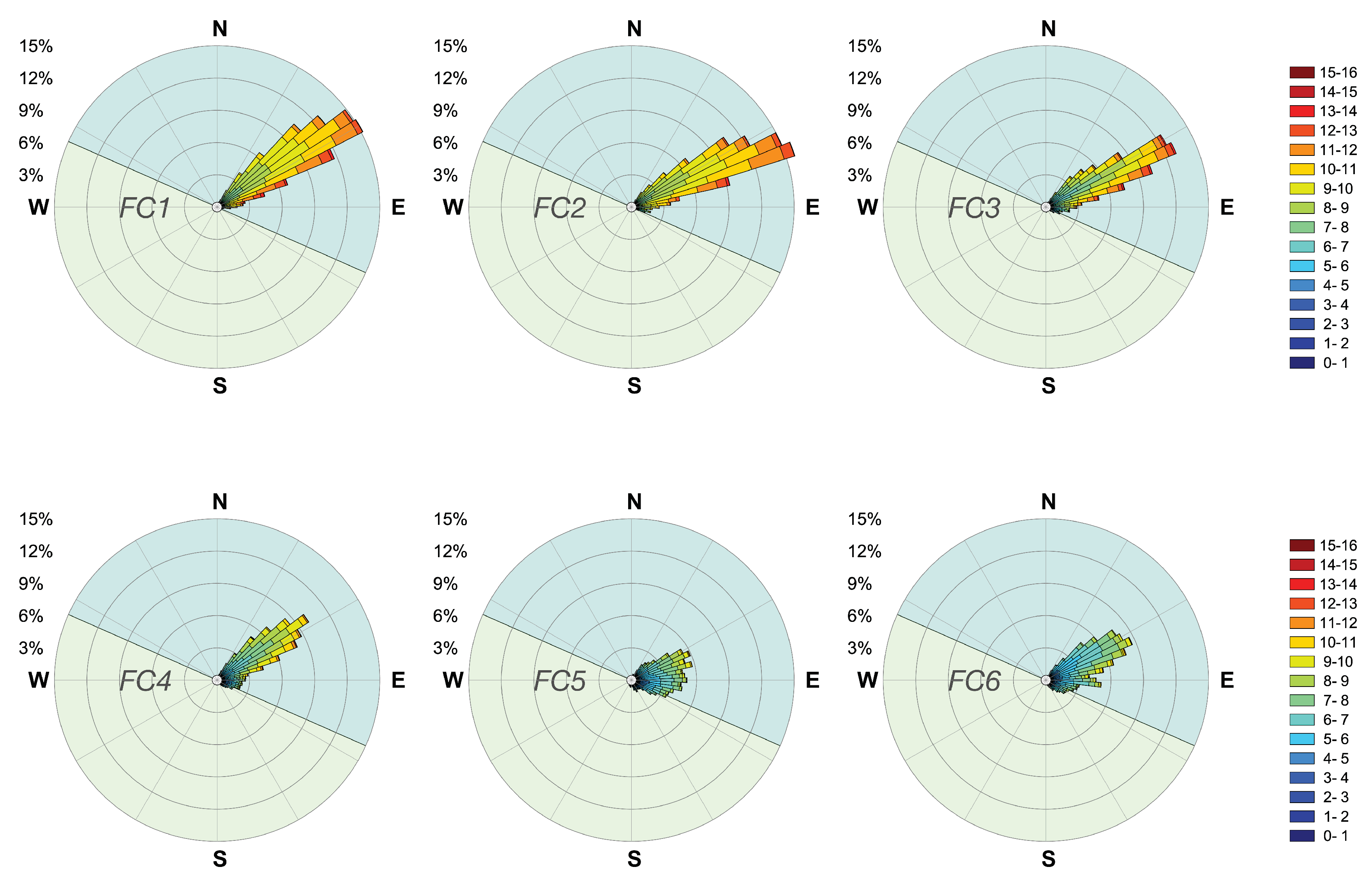
Figure 6 illustrates wind roses for all field campaigns covered by monitoring station P1. Winds are clearly dominant from NE during campaigns FC1 to FC3, also presenting the narrower directional spread and the stronger observed events (11 to 14 m s 1 ). Easterly flows start to be noticeable on FC4 but become dominant on FC5 where the largest directional spread and weaker speeds occur.
A visual inspection of these wind roses suggests winds from the southeast vary for P1. Winds with angles larger than 90° (E) blew 4.1% of time during FC1, 10.3% for FC2, 19.6% for FC3, 23.8% for FC4, 46.2% for FC5 and 32.1% for FC6. The percentage of occurrences of winds from the ocean sector (294° to 114°) are 99.6% (FC1), 97.2% (FC2), 89.3% (FC3), 84.6% (FC4), 73.4% (FC5), 84.6% (FC6).
Winds blowing near parallel or from the land sector encounter more roughness elements before reaching point P1 and are characterized by lower wind speeds. This suggests that coastal wind resources of eastern Maranhão are sensitive to the wind direction.
In summary, winds from the northeast were predominant during the dry period, with modal speeds between 9 and 9.5 m s 1 and wind speeds exceeding 10 m s 1 more than 31% of the time. During the wet season, modal speeds were between 5.5 and 6 m s 1 and the importance of east and southeast wind components increased. Less than 13% of the time winds exceeded 10 m s 1 and the majority of the time the wind skewness was around zero or positive.

3.2.3. Mean Vertical Profiles

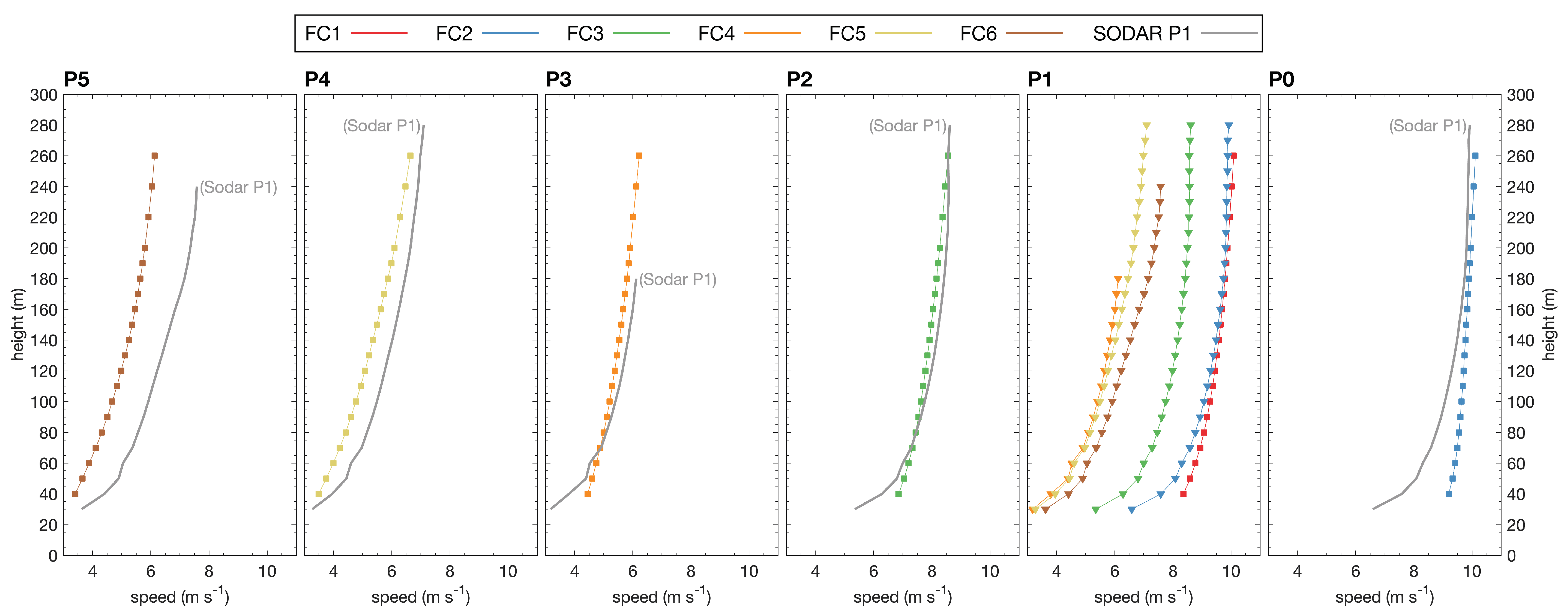
Wind speed mean vertical profiles for the six field campaigns are displayed in Figure 7. Individual panels represent the position of profiles. Coastal station P0 is on the right and point P5 is on the left of the figure. Line colors indicate the profiles taken at these positions as a function of the field campaign: FC1 (red line), FC2 (blue), FC3 (green), FC4 (orange), FC5 (golden) and FC6 (brown). Additionally, symbols on these profiles identify the source of observations: squares representing the LIDAR and inverted triangles identifying the SODAR. Gray lines without symbols are also drawn on panels P0 and P2 to P5 in order to facilitate the visual comparison of simultaneous measurements. These lines represent profiles obtained at the monitoring station P1 by the SODAR.
Periods considered in these comparisons and the specific positions of the LIDAR and SODAR are listed in Table 2. Specifically for FC4, SODAR suffered a major data loss, so the period of comparison was limited to 6 March 2022 to 18 April 2022. Additionally, a criterion of 50% valid data for each height was applied, which limited the height of some profiles measured by the SODAR.
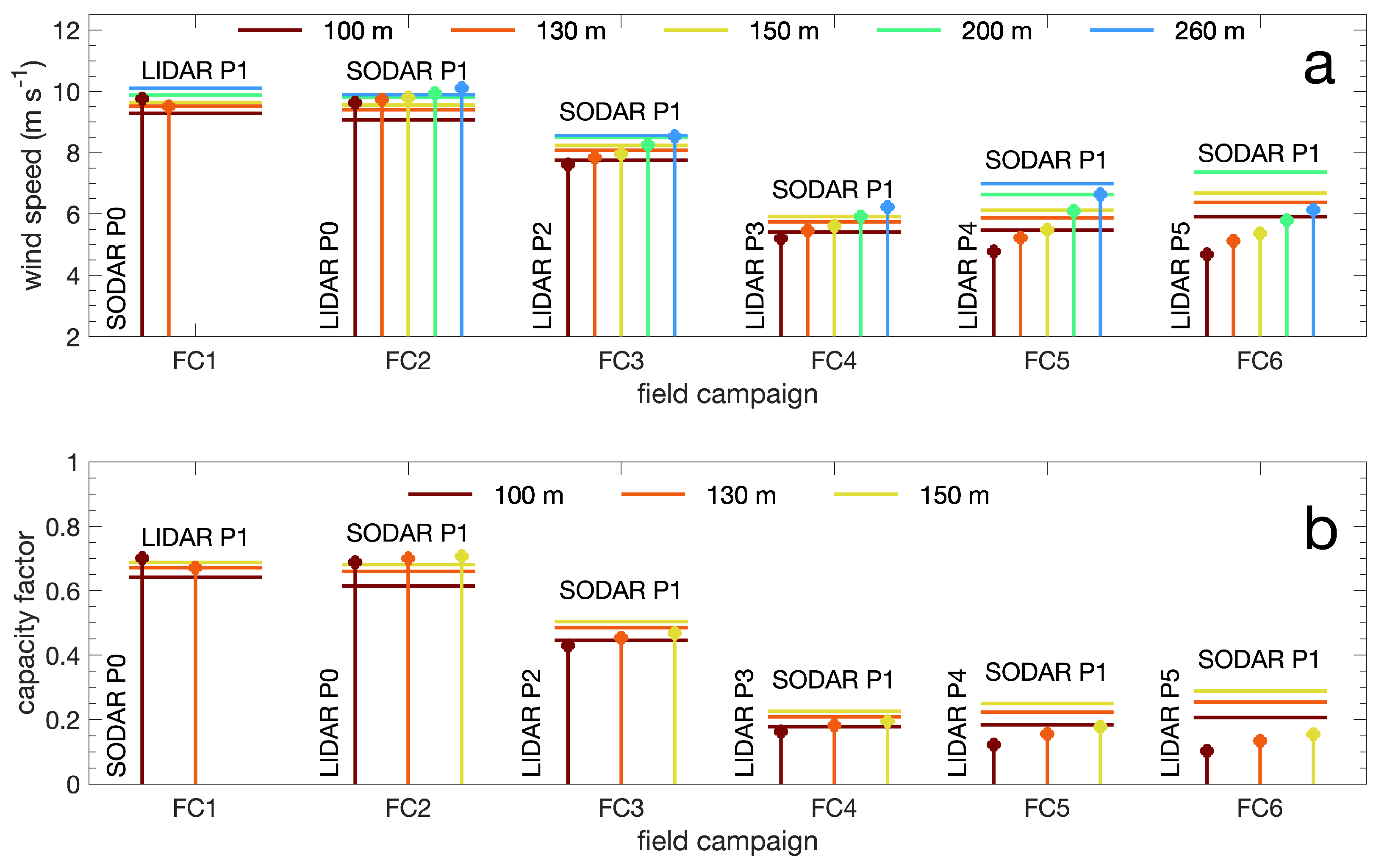
Panel P1 presents the most complete sequence of data, with vertical profiles plotted for all the field campaigns. This graph clearly illustrates the seasonal change. A large similarity between the first (FC1, red) and the second campaign (FC2, blue) profiles was observed. Wind speeds were 9.3 m s 1 at 100 m and 10.1 m s 1 at 260 m height (Table 4) during the dry season. Profiles presented very little shear at higher levels. The most significant differences between FC1 and FC2 were observed in the lowest 80 m. With the southward migration of ITCZ, winds started decaying in magnitude, reaching 7.75 m s 1 and 8.56 m s 1 , respectively, at 100 and 260 m heights on FC3 at P1.
The lowest wind speeds were recorded during the rainiest period, 5.41 m s 1 at 100 m height for FC4 (Figure 4). Wind magnitudes started recovering after June 2022, when vertical profiles for FC5 and FC6 started shifting to higher speeds, respectively, reaching 5.47 and 5.91 m s 1 at 100 m. Most significant changes of vertical wind shear ( U / z ) at P1 occurred in the lowest 130 m.
Panel P0 illustrates the LIDAR mean vertical profile compared to the SODAR profile measured at P1 for the second field campaign FC2. Average speeds at 260 m height are 10.10 and 9.89 m s 1 , respectively, for P0 (LIDAR) and P1 (SODAR). At the height of 100 m, speeds are 9.63 (P0) and 9.07 m s 1 (P1). At 40 m height, speeds are 9.21 (P0) and 7.54 m s 1 (P1). Speed differences, induced by terrain, increased for levels below 130 m. Differences were 0.20 m s 1 at 260 m, 0.56 m s 1 at 100 m and 1.67 m s 1 at 40 m.
Panel P2 illustrates the LIDAR and SODAR profiles for field campaign FC3. Speeds are, respectively, 8.56 and 8.54 m s 1 at 260 m and 7.75 and 7.61 m s 1 at 100 m. Profiles are very similar above 80 m height but deviate in lower levels so that differences reached 0.57 m s 1 at 40 m. Panel P3 presents similar results for the field campaign FC4. SODAR speeds at P1 are slightly larger than the LIDAR at P3. Average speeds are 5.92 and 5.61 m s 1 at 150 m; 5.41 and 5.21 m s 1 at 100 m height. These differences tend to vanish at 70 m. Below this level, the SODAR vertical shear was stronger than the shear reported by the LIDAR. Differences reached 0.65 m s 1 at 40 m height.
Panel P4 illustrates the mean vertical profiles during field campaign FC5, when the LIDAR was positioned 26 km west from station P1 (Figure 1b). Differences between P1 and P4 curves were positive and significant for all observed levels, suggesting that the terrain effect is impacting the entire wind profile. Speed differences between these heights varied from 0.34 to 0.70 m s 1 . Wind speeds were 6.98 (P1) and 6.64 m s 1 (P4) at 260 m, 6.12 and 5.49 m s 1 at 150 m and 5.47 and 4.77 m s 1 at 100 m height.
Panel P5 finally compares the mean LIDAR profile from point P5 with the SODAR profile taken at P1. Station P5 is west of the Barreirinhas urban area, 6.1 km southwest of P4 and 32 km inland from P1. Profile differences not only remained significant for all observed levels but also increased. Speed differences found between P1 and P5 averaged profiles varied from 1.23 to 1.54 m s 1 . Wind speeds were 7.57 (P1) and 6.03 m s 1 (P5) at 240 m, 6.68 and 5.36 m s 1 at 150 m and 5.91 and 4.68 m s 1 at 100 m height.
In summary, mean vertical profiles at station P1 described a dominant seasonal signal with changes on the order of 3.5 to 3.8 m s 1 between the windy and rainy seasons. Significant spatial variability of winds was observed, comparing stations P0, P2, P3, P4 and P5 with simultaneous measurements of point P1. Considering the height of 100 m above the ground, the order of magnitude of this decay was 0.5 m s 1 between P0 and P1, less than 0.2 m s 1 for P1 with P2 or P3, 0.7 m s 1 for P1 with P4 and 1.23 m s 1 for P1 with P5.
The mechanism behind this “spatial decayment” is related to terrain roughness and will be explored in Section 3.3.1, with analysis of micrometeorological tower data. The mean wind profiles suggest that the frictional internal boundary layer is shallower than 130 m in the vicinity of Paulino Neves (points P1, P2 and P3), but seems to grow to all observable heights (>260 m) near Barreirinhas county (P4 and P5).

3.2.4. Diurnal Variability of Speeds

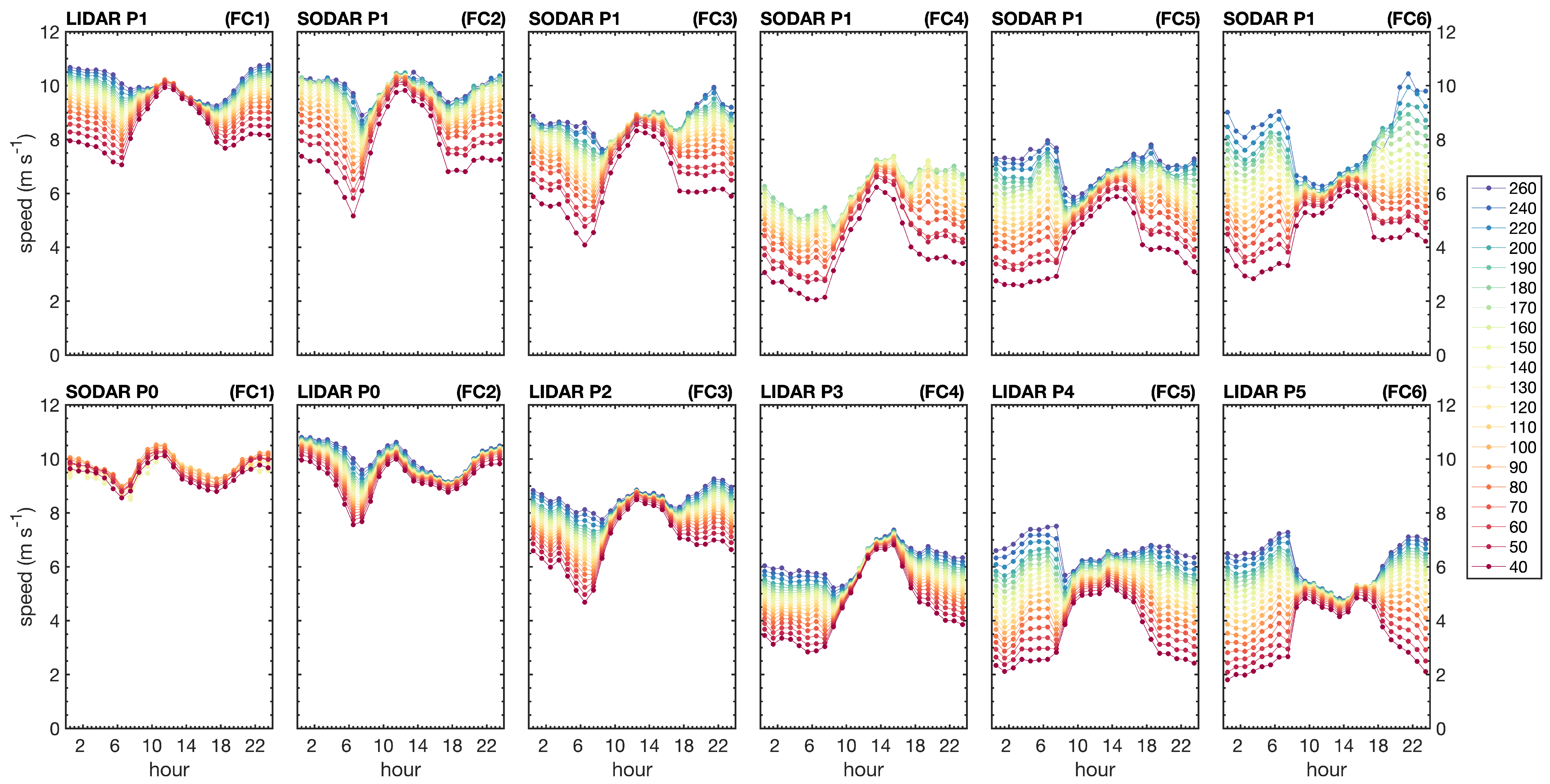
Figure 8 explores the diurnal variability of wind speeds as a function of field campaigns, locations and height. Results demonstrate the seasonal variability already described in the previous sections, with winds progressively decaying in magnitude from FC1 (left panels) to FC4 (middle) and then slowly recovering in FC5 and FC6 (right). It also evidences important changes of the wind vertical shear ( U / z ) and how peak wind magnitudes change with time and height.
In general terms, winds demonstrated the largest vertical shears in the early morning (0 to 6 h) and late night (18 h to midnight) and the weakest shear around midday (12 h). As an example, station P1 during FC1 presented U∼10.7 m s 1 at 260 m and U∼7.9 m s 1 at 40 m before sunrise and after sunset. This corresponds to a difference of Δ U = 2.8 m s 1 between these levels. At midday, this difference reduces to near one-tenth of this magnitude at Δ U = 0.25 m s 1 .
Comparing the wind shear of station P1 across its different field campaigns, it also becomes clear how shear increases over time. Speed differences with height on FC6 can reach Δ U = 5.1 m s 1 in the early morning and late evening. At noon, these differences are Δ U = 1.0 m s 1 . The reasons for this variability seem to be linked to surface heat fluxes, friction velocities and wind direction as will be explored in Section 3.3.
When comparing wind speed shear for different station positions, differences between P0 and P1 stand out. While midday vertical shears are relatively similar, early morning and late night shears are much larger for P1. P0 wind speed vertical differences between 40 and 260 m are Δ U = 2.3 m s 1 at 6 h and Δ U = 0.5 m s 1 at midnight during FC2. These numbers at P1, respectively, grow to Δ U = 4.4 m s 1 at 6 h and Δ U = 3 m s 1 at midnight during FC2. The diurnal regime of P0 during FC1 looks similar to FC2, but the SODAR data loss precludes an analysis of the wind shear above 130 m.
Station P0 is the closest point to the ocean, around 1.5 km from the beach. Airflow at this location presumably carries strong characteristics of the oceanic boundary layer but experiences the impact of terrain roughness and ground heat fluxes when winds are near parallel to the coast or blowing from land.
Finally, peak wind magnitudes seem to occur at midday (∼12 h) and midnight (24 h) for station P1 (FC1 to FC3), station P0 (FC1 and FC2) and station P2 (FC3). Station P3 during FC4 demonstrates a midafternoon (14 h) wind speed peak. Field campaigns FC5 and FC6 demonstrate peak speeds in lower levels (<100 m) at midday (10 to 16 h), but troughs in higher levels for the same hours. Peak speeds in higher levels occur during the early morning and night on FC5 and FC6. Points P4 and P5 do not have peak values during the hours of atmospheric instability (9 to 17 h), indicating that the terrain roughness and heating have greater importance for the flow behavior. The following section will explore the dataset through the use of wind hodographs in order to explore the interaction of the sea–land breezes with the Trades.

3.2.5. Diurnal Hodographs

In coastal regions, the land surface warms and cools more rapidly than the ocean in response to daytime solar heating. The resulting cycle of air temperature differences over the land and the ocean generates local pressure gradient forces that drive the sea and land breezes [15,64,65]. Coriolis force might further induce an oscillating along-shore component, so that the wind vector might rotate in the course of a day [66]. As diurnal winds and the mean scale flows are additive, hodographs can be used to study the interplay of the breezes with the mean atmospheric circulation [67,68]. In this analysis, winds are represented as:
v ( t ) = v m + v b ( t ) ,
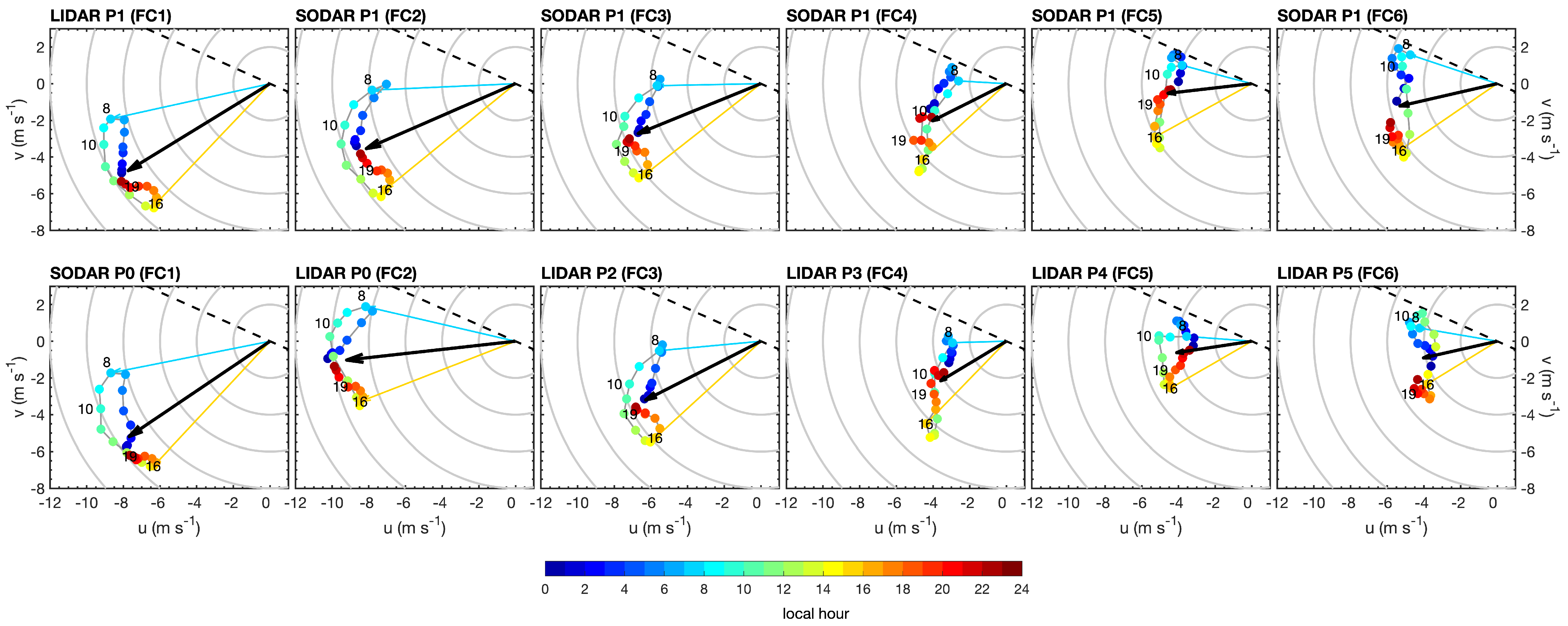
where v ( t ) represents the hodograph vector, v m is the mean flow and v b ( t ) is the breeze component. The mean flow vector represents the large-scale circulation and its average considers all observations available for each field campaign. The hodograph vector is evaluated by taking the average u and v wind components for each hour of the day. The breeze component can be evaluated from v b = v v m . All vector components were vertically averaged between the levels of 100 and 130 m.
Results are illustrated in Figure 9 for both wind profilers and all field campaigns. A light blue arrow depicts the hourly wind vector for 8 h, near the peak of the land breeze. Conversely, an orange arrow indicates the hourly wind vector at 16 h, near the maximum sea breeze. For all other hours, vectors are omitted and their ends are represented by bullets, with colors indicating the local time. A line connects all bullets closing the diurnal cycle in the form of the hodograph.
During the field campaigns, there were significant changes in the mean flow, drawn as thick black arrows in Figure 9. The Trade winds blew from the northeast at nearly 10 m s 1 during FC1, gradually decreased to 7 m s 1 during FC3 and changed their orientation to easterly winds with a strength of 4 m s 1 in FC6 (Figure 9).
Hodographs illustrate the hourly changes of winds during the course of a day. In the early morning, near sunrise, air temperatures over land are still colder than in the ocean. The surface pressure gradient force points towards the ocean, so that the land breeze is fully developed. The peak of the land breeze seems to occur near 8 h as indicated by the blue vectors of Figure 9. As the day progresses, air temperature increases due to solar radiation over land, so that the local atmospheric pressure gradient force reverses and the sea breeze start to develop. The peak of the sea breeze seems to occur near 16 h, as suggested by the orange vectors of Figure 9.
Simplified theory of the sea breezes predicts hodographs in the shape of ellipses, with anti-clockwise (clockwise) direction in the southern (northern) hemisphere [67]. Hodographs shown in Figure 9 demonstrated deformed elliptical shapes, mostly with anti-clockwise rotations (FC1 to FC3) with some degenerating to rectilinear (FC4) or more complex forms. Breezes’ amplitudes demonstrate magnitudes on the order of 4 m s 1 during FC1, decaying to near 2 m s 1 at FC5. The amplitude reduction is presumably related to a decrease in land–ocean air temperature gradients due to the increased cloud cover and precipitation during FC4, FC5 and FC6 [15].
Observed hodographs are by no means as regular as the theory predicts and differences in form and orientation can be attributed to other causes such as the friction, complexity of coastline, wind convergences and divergences, variability of temperature forcing and atmospheric stability [67,68].
Figure 9 demonstrate that hodographs were oriented towards the northwest–southeast during FC1, FC2 and FC3, while during FC4, FC5 and FC6 they were nearly oriented in north–south directions. Changes in sea breeze orientation might be linked to mesoscale forcing or even the presence of Lençóis Maranhenses National Park, a region covered with permanent dune fields and lakes (Figure 1b).
Sea and land breeze orientations relative to the mean wind vector help to explain the complex diurnal profiles of wind speeds obtained in Figure 8. During FC1 and FC2 field campaigns, hodographs were generally perpendicular to the mean flow, but with the breeze component v b slightly oriented against the mean flow. As a consequence, the lower wind speeds were obtained at the peak of the land and sea breezes. The largest speeds were observed at midday and midnight during these field campaigns.
During field campaign FC4, the breeze orientation was relatively aligned to the mean wind speed vector, so that the sea breeze reinforced the large-scale flow, reaching maximum wind speeds of 7.3 m s 1 near 16 h. Conversely, the land breeze opposed the mean flow near 8 h when the lower speeds were observed (Figure 8 and Figure 9).
Field campaigns FC5 and FC6 hodographs are generally oriented north–south and perpendicular to the mean wind speed vector. At the height of 100 m and for higher levels, peak speeds occurred at 8 and 21 h (Figure 9). For lower levels, peak speeds occurred between 9 and 16 h (Figure 8).
Stations P1 to P3 were 4.5 to 8.35 km distant from turbines of the eastern limit of the wind park, while points P4 and P5 are too far for any wind turbine influence (Figure 1b). Station P0 was 2 km from the front row of turbines but outside the direction of predominant winds.

3.3. Micrometeorology and Profile Characterization

Towers recorded micrometeorological data for all field campaigns, providing frictional velocity and surface heat fluxes. These series were analyzed and used to estimate the roughness parameter and the Obukhov length for the classification of atmospheric stability. The results of this analysis are presented and compared with shear exponent estimates obtained from the wind profilers.

3.3.1. Roughness Length and Friction Velocity

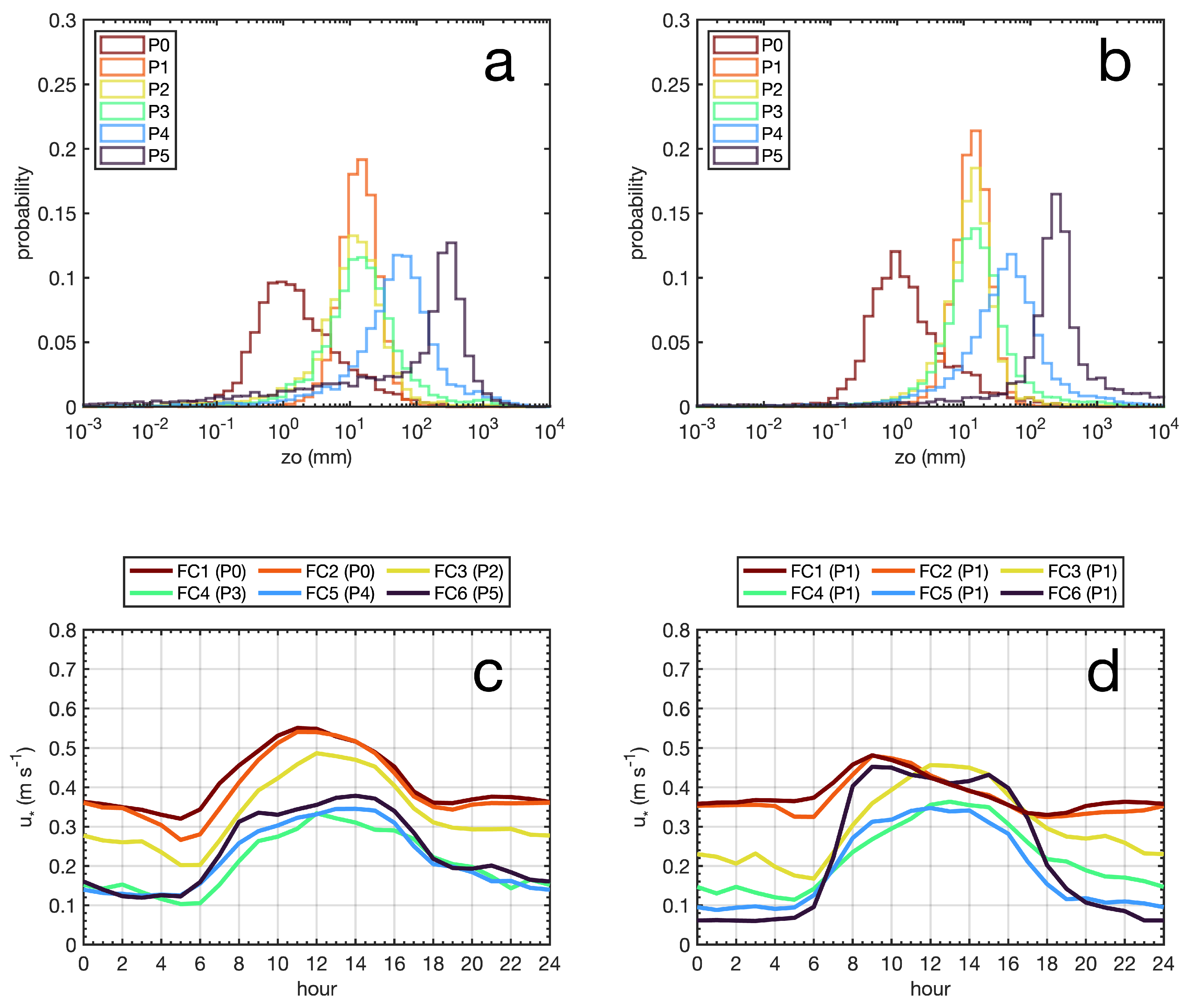
Field campaigns were conducted in different locations in order to access the effects of the terrain characteristics over the wind vertical profiles. Micrometeorological tower data were used for the roughness length z o estimation given by Equation (5), employing 10 min averages of friction velocity u , stability function ψ ( z / L ) and the reference wind speed U r . Results are illustrated in Figure 10a,b, where the line colors represent the probability distributions obtained for stations P0 to P5. Figure 10a assumed a neutral atmosphere ψ = 0, while results of Figure 10b included the stability functions described in Section 2.4.
Resultant z o distributions ranged from 10 2 to 10 3 mm. Station P0 was displaced to the left of the graph, while P1, P2 and P3 histograms were in the middle and aligned in reference to each other. P4 distribution was on the right and P5 on the far right end of the graph. Differences between Figure 10a,b were subtle. The inclusion of the stability function ψ improved z o calculation, generating narrower distributions with sharper modal peaks, also grouping similar terrains, such as P1, P2 and P3.
Statistics of z o are listed in Table 6 in terms of modal and median values. Station P0, located near the beach, presented the lowest z o distributions, with a modal value at 0.95 mm and a median of 1.19 mm, magnitudes that are typical of blown sea and smooth surfaces [6]. Stations P1, P2 and P3 were positioned between 5.6 ad 7.7 km from the beach, but between 2 and 3.3 km from each other. Their z o distributions were very similar and presented a modal value of 15.33 mm and median varying from 12.83 to 15.15 mm, on the order of magnitude of rough pasture terrains [6]. Station P4 presented a modal value of 52.68 mm and a median of 43.65 mm, typical of landscapes with crops and bushes. Finally, station P5 presented modal z o of 246.46 mm and a median of 255.25 mm, typical of terrain with trees, hedges and small buildings [6]. Statistics were similar when considering neutral conditions (Table 6).
Figure 10 lower panels present the diurnal variability of u for different campaigns and stations. Line colors represent the different field campaigns, from FC1 to FC6. Figure 10c presents the distributions for the mobile micrometeorological tower that covered points P0 and P2 to P5. Figure 10d presents the results from the micrometeorological tower positioned at point P1 as a function of field campaigns.
Overall magnitudes of friction velocity varied from less than 0.10 m s 1 up to 0.55 m s 1 , presenting similar diurnal cycles. Higher magnitudes were generally observed between 6 and 18 h, despite the season or position. Lower magnitudes were expected for the early morning before sunrise and at night after sunset. The amplitude of the diurnal cycle varied from 0.20 m s 1 to 0.30 m s 1 .
Curves suggest that the variability of friction velocities with campaigns is directly related to wind speeds. All u curves were higher for the periods when Trade winds were more intensified (FC1 to FC3) and lower for the periods when the ITCZ was present (FC4, FC5). Comparing stations for the same field campaigns, some differences were apparent. Point P0 (red curve) presented higher midday peaks than point P1 for the field campaigns FC1 and FC2 (red and orange curves). Likewise, midday amplitudes during FC6 are 0.2 m s 1 for point P5, compared to 0.4 m s 1 for station P1 (dark blue). Friction velocity distributions of P1 during field campaigns FC3 and FC4 (yellow and green) are very similar to P2 and P3, as expected due to the proximity of these stations.

3.3.2. Buoyancy Heat Fluxes

Micrometeorological tower measurements further provided turbulent quantities for the calculation of buoyancy heat fluxes from Equation (4). Results are summarized in Figure 11 for all stations and field campaigns.
Heat fluxes presented bell-shaped curves, with positive fluxes between 6 and 18 h, during daylight hours. The largest positive fluxes occurred on field campaigns FC1 and FC2, with peaks during noon that varied from 250 to 320 W m 2 . Night-time heat fluxes before sunrise (0 to 6 h) and after sunset (18 to 24 h) were dominantly negative during FC1, FC2 and FC3, indicating the ground cooling the atmosphere. Magnitudes were on the order of −10 to −20 W m 2 . In statistical terms, these negative fluxes occurred from 87 to 100% of time at stations P1 and P2. Positive fluxes could be observed for station P0 during FC1 and FC2 after sunset, with occurrences 42 to 60% of the time (Figure 11).
Field campaigns FC4 and FC5 were characterized by much-reduced fluxes during midday and variable fluxes during dark hours. Midday positive fluxes reached values as low as 77 W m 2 during midday, which is nearly 20% of the magnitudes observed during FC1 and FC2. These changes were presumably associated with the increased cloud cover and precipitation due to the ITCZ. Reduced ground heating during the day implies weaker upward heat fluxes. Wet soils also tend to present lower diurnal cycles of temperatures.
Positive fluxes were observed in dark hours for FC4 and FC5 campaigns before sunrise. This occurred near 61 to 83% of the time at station P1, 38% of the time at P3 and 74% of the time at P4. After sunset, positive fluxes were observed 36 to 48% of the time at station P1, 23% at P3 and 54% at P4. The occurrence of nighttime positive fluxes was associated with the presence of small freshwater ponds formed by precipitation. These ponds were observed in the dune fields of Paulino Neves (P1 and P3) and Barreirinhas airport (P4) (see Figures S1–S3 in Supplementary Materials). Freshwater ponds tend to store heat during the day and release heat during the night, which explains the weak positive fluxes observed in dark hours. Depending on the situation, FC4 and FC5 also presented negative night fluxes, with occurrences of 17 to 61% of the time before sunrise (0 to 6 h) and 46 to 76% of the time after sunset (18 to 24 h).
Field campaign FC6 demonstrated an increase in midday heat fluxes, 105 W m 2 for P1 and 187 W m 2 for P5. This is presumably a result of the ITCZ northward migration, which tends to reduce the cloud cover and precipitation over Maranhão (Figure 3). There was also a noticeable increase in cooling periods during dark hours, 43% to 77% before dawn and 90 to 94% after dusk.
Heat flux differences among stations for the same field campaigns are probably associated with terrain properties. For instance, during FC1 noontime heat flow can peak at 320 W m 2 at P1 but 275 W m 2 at P0. P0 is characterized by white sands with large albedo, while P1 terrain is characterized by darker colors associated with organic content, which presumably reach higher temperatures during the day. P1, P2 and P3 have very similar terrains so their diurnal fluxes are very similar. During field campaign FC6, daylight surface heat fluxes are larger for P5, in comparison to P1. This might be associated with the urban characteristics of station P5. The impact of nighttime heat fluxes observed for FC4 and FC5 on stability classification and wind shear will be explored in the next sections.

3.3.3. Obukhov Length and Stability Classification

Obukhov length L was computed for the classification of atmospheric stability. L depends on the buoyancy heat flux and the friction velocity, which were computed from the high-frequency sonic anemometer data. As previously explained, the magnitude of L represents the height where frictional shear dominates over buoyancy effects. It presents the opposite sign of the buoyancy heat flux, such that positive and negative heat fluxes are characterized by L < 0 and L > 0 , respectively.
A wide range of limits defining stability classes has been employed in previous works. Table 7 summarizes some studies, grouping their limits into five main classes: neutral, convective, strongly convective, stable and strongly stable. Van Wijik et al. (1990) and others [69,70,71,72,73] classify neutral conditions by | L | > 1000 m, while Warthon and Lundquist (2012) [36,74] use | L | > 600 m. Archer et al. (2016) [37], Gryning et al. (2007) [35,75] and Sakagami et al. (2015) [29] classify neutral | L | > 500 m. The two latter references further include near-neutral unstable (−500 L < −200) and near-neutral stable (200 < L 500) conditions in a total of seven classes. Here, these classes are grouped together as neutral for | L | > 200 m (Table 7).
Limits separating convective and strongly convective conditions vary from L = −200 to L = −50 m between these studies, while the limits separating strongly stable from stable conditions vary from L = 50 to L = 200 m (Table 7). Here, we classify neutral conditions as | L | > 200 m but define the limits for strongly convective with −40 L < 0 m and strongly stable conditions as 0 < L 40 m (Table 7). The heights of 40 m and 200 m are close to the heights of modern wind turbine rotors.
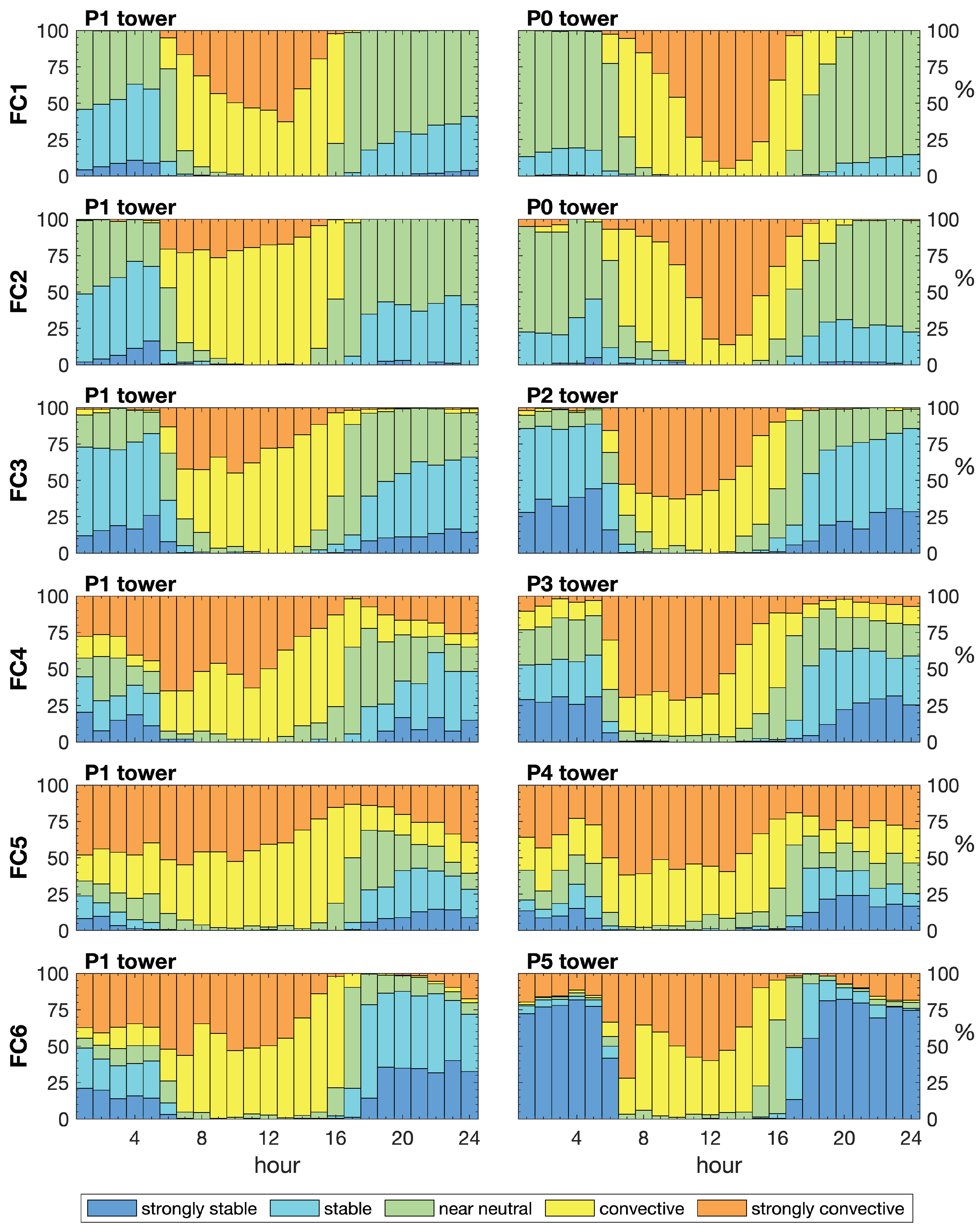
Results of this classification scheme are presented in Figure 12 for all stations and field campaigns of EOSOLAR. Diurnal classification for the periods covered by FC1, FC2 and FC3 demonstrate relatively similar distributions. Neutral to stable and strongly stable conditions are observed before sunrise at 6 h and after sunset at 18 h, while convective to strongly convective conditions prevail between 8 and 16 h. At midday, station P1 suggests strongly convective conditions from 25 to 50% of the time, against 80% strongly convective conditions at P0 tower for FC1 and FC2 and near 50% at P2 for FC3.
Strongly stable conditions were observed preferably before sunrise for P1 tower on FC1 and FC2, varying from 10% to 15% of the time. Neutral conditions are predominant in dark hours for P0, with occurrences generally larger than 75%.
Stable and strongly stable conditions during dark hours were more frequent during FC3, respectively reaching 25 and 75% of the time (Figure 12). As the magnitude of negative heat fluxes was relatively similar between FC1 and FC3 (Figure 11), the increase in stable conditions is presumably attributed to a reduction in friction velocity in FC3 (Figure 10). The predominance of strongly stable conditions in the early morning and near the beach was also observed for Pedra do Sal at Piauí state 96 km west of Paulino Neves [29].
The diurnal cycle of stability changed substantially for FC4 and FC5 campaigns. Convective to strongly convective conditions were not only present during midday but are also observed during nighttime. At midnight, their percentage of occurrence reached 18% for convective and 47% of time for strongly convective conditions at P1 during FC5. These conditions were in agreement with the positive nighttime heat fluxes reported for FC4 and FC5 campaigns (Figure 11). Unstable conditions were attributed to the presence of wet soil and the formation of freshwater pools, which tend to store heat during the day and release it at night. Auxiliary Figure S1 illustrates the freshwater pools that were formed around the P1 station during FC4. Figure S2a presents a historical satellite image illustrating the size of wet pools formed in the vicinity of points P2 and P3 (satellite imagery was not available for the period of FC3 or FC4).
Nighttime convective conditions were enhanced during FC5 conducted from 20 April to 13 June 2022 (Figure 12). Figure S3a satellite imagery illustrates the extension of freshwater pools formed in the vicinity of station P4 in March of 2022. These were distributed around the airport and to the northeast and southeast of the P4 location. Some freshwater pools could reach 600 m in length. These pools were gone by the month of September 2022 during the dry season (Figure S3b).
Stations P1 and P5 during FC6 demonstrated an increase in the occurrences of strongly stable conditions during the night. FC6 was considered a transitional period, when the ITCZ started to move northward and the accumulated precipitation was reduced to 75 mm. Strongly stable conditions were related to the increase in negative heat flux events and especially the very reduced frictional velocities observed for P5 (Figure 12).
FC6 convective to strongly convective conditions were predominant during midday but also demonstrated significant occurrences of strongly convective conditions before sunset and after sunrise. Midnight strongly convective conditions could reach 37% of time at P1, compared to 19% at P5. Unstable conditions during nighttime are probably associated with remaining freshwater pools at P1, the surrounding vegetation and the presence of the Preguiças River (Figure 12). The impact of nighttime positive heat fluxes during EOSOLAR seemed to be very local, without much influence over the wind profiles, as will be demonstrated in the next subsection.

3.3.4. Shear Exponent Diurnal and Directional Variability

Winds in the lower surface layer over land usually undergo strong diurnal changes in vertical shear that might be overlooked with daily or monthly averages [6,60]. Analysis of the shear exponent α was performed for all LIDAR and SODAR wind profiles through the use of Equation (7) outlined in Section 2.5.
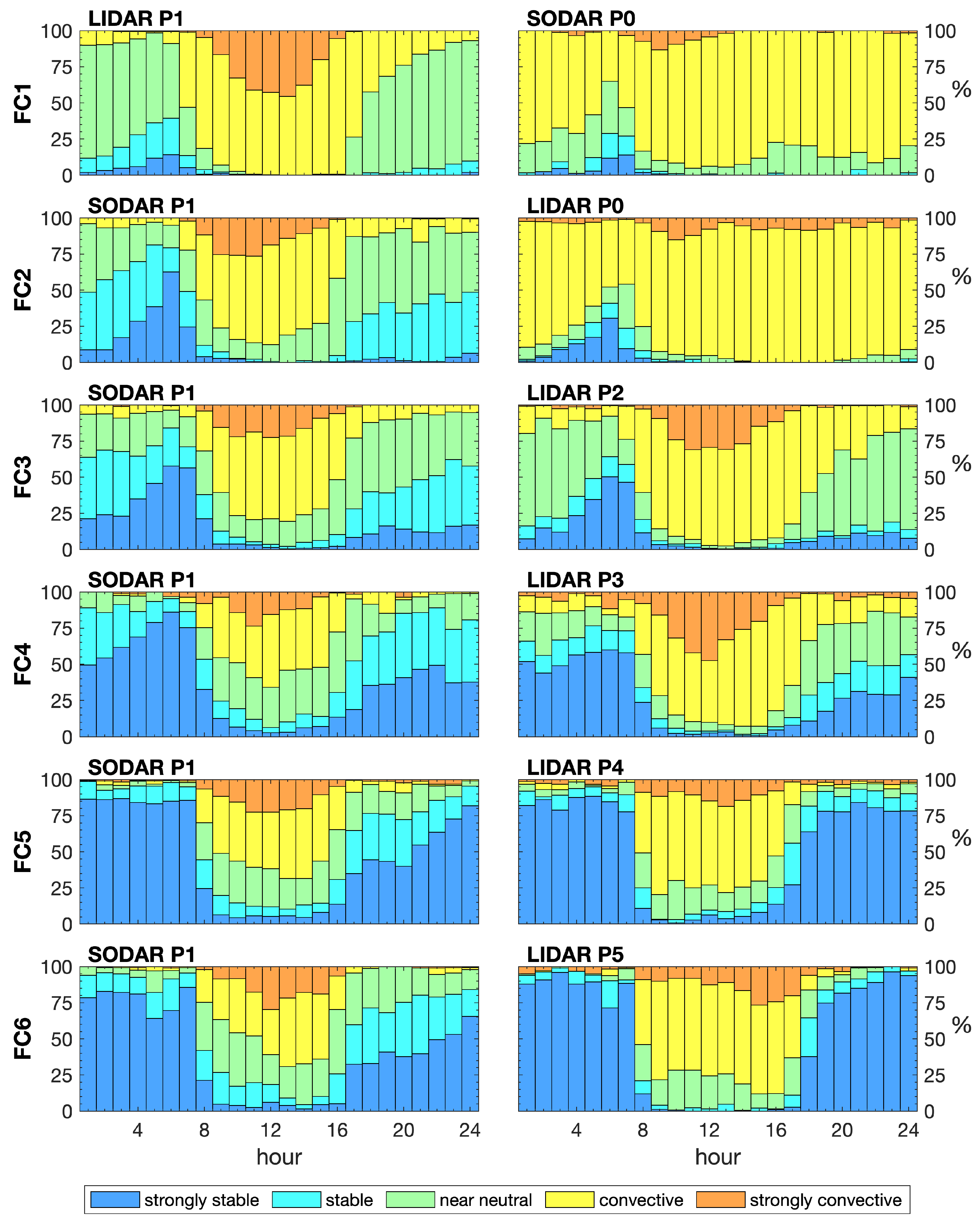
Shear classification followed the procedure of Wharton and Lundquist (2012) [36] that separates wind profiles according to five main groups: strongly stable ( α > 0.3 ), stable ( 0.2 < α 0.3 ), neutral ( 0.1 < α 0.2 ), convective ( 0.0 < α 0.1 ) and strongly convective ( α 0 ). As a general rule, the value of the shear exponent is expected to decrease with heating from below (convective conditions) and increase with surface cooling (stable conditions). Results are presented in Figure 13 for all EOSOLAR stations. Each panel on this figure presents the diurnal cycle of the shear exponent based on wind profile observations.
P0 demonstrated a remarkable resemblance for field campaigns FC1 and FC2. Convective profiles were present during daylight and nighttime hours, with occurrences that could reach 80 to 100% of the time. Strongly convective conditions were typically less than 5% but could reach 15% during midday. Neutral conditions occurred between 10 to 35% of the time. Stable to strongly stable profiles were only observed from 0 to 8 h, reaching a peak of 25% near dawn (Figure 13).
These shear profiles did not agree with the stability classification presented in Figure 12 for P0. Obukhov length described a dominance of neutral conditions during nighttime and strongly convective conditions at midday, while shear exponents were dominantly convective. This suggests that profiles were subject to the strong influence of the ocean’s atmospheric boundary layer, since P0 was the closest station to the beach. This is in agreement with previous studies on the northeast that have demonstrated neutral to unstable conditions over the ocean from radiosonde [15], tower [17,22] and climatological data [10]. The distributions illustrated in Figure 13 suggest that the atmospheric boundary layer maintains the ocean’s convective characteristics most of the time, except for the early morning when stable conditions become important during the peak of the land breeze (Figure 9).
Winds blowing from the ocean sector will experience a fetch over land that can be approximated from:
d f e t c h = d c o a s t s i n ( θ c o a s t θ w i n d ) .
Here, d c o a s t represents the station distance to the coastline, θ c o a s t is the coastline orientation and θ w i n d is the wind direction relative to true north. For EOSOLAR study area θ c o a s t ∼114°. θ = θ c o a s t θ w i n d represents the wind angle relative to the coastline (see Figure S4). Equation (10) demonstrates that as winds approach the coast at normal angles, d f e t c h d c o a s t and they experience the shortest fetches over land. Conversely, as winds blow with small angles relative to the coastline and θ becomes small, d f e t c h will grow unbounded.
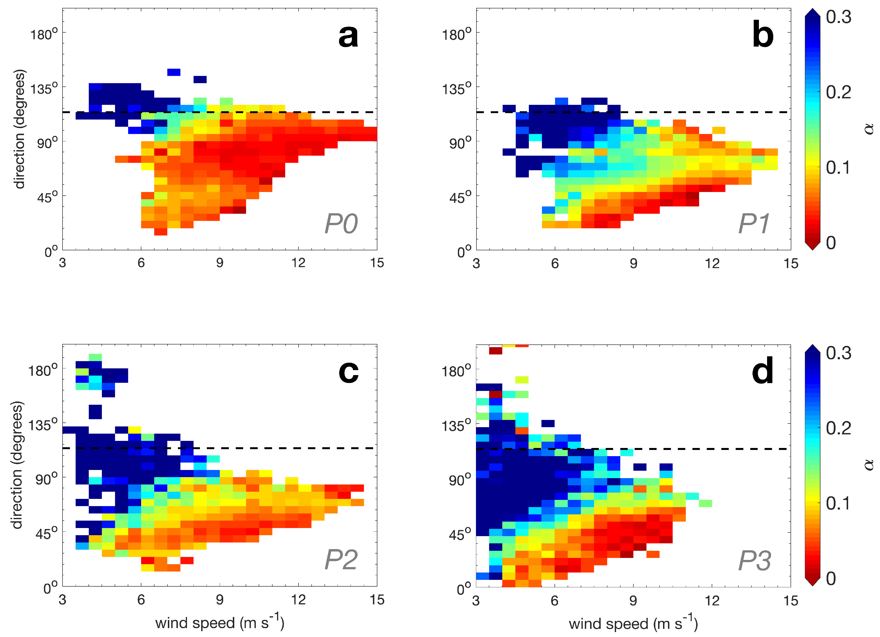
Figure 14a further explores the influence of wind direction over shear for station P0. Each panel on this figure displays the shear exponent as a function of wind speed and direction measured at 100 m height. The average shear is computed based on individual shear observations distributed over a grid with 0.5 m s 1 × 6° bins. A dotted line illustrates the coastline orientation. P0 distribution clearly illustrate that low shear winds blow preferably from the north and northeast. Shear is substantially increased as winds start to blow near parallel to the coast or from the land sector. Considering d c o a s t = 1.5 km for station P0, it can be shown that fetch will grow to d f e t c h = 7.2 km for wind relative angles of θ = 12°.
Internal boundary layers typically grow inland as a function of temperature differences and wind fetch [40]. Fetch is relatively short for the profile adjustment to surface flux conditions when winds are blowing directly from the ocean. This often occurs at P0 near the peak of the sea breeze, around 16 h (Figure 9). On the other hand, during the land breeze winds approach the shore with smaller angles of incidence (Figure 9 and Figure 14). This implies longer fetches that allow wind profiles to adjust to the nighttime surface fluxes. This seems to occur between 4 and 8 h for P0 (Figure 13). Obukhov classification for this location describes stable to strongly stable conditions during this time (Figure 12).
Wind shear at station P1 demonstrates a much closer resemblance to the surface conditions estimated from the Obukhov length classification on field campaigns FC1 and FC2 (see Figure 12 and Figure 13). This suggests that wind profiles are in closer equilibrium with heat fluxes, as the surface conditions generally agree with the observed wind shear. Compared to station P0, station P1 demonstrated substantial growth in the occurrence of strongly convective profiles near midday and neutral to stable and strongly stable conditions during the night. The occurrence of strongly stable profiles was larger for station P1 during FC2, presumably due to the stronger landward component of the land breeze (Figure 9).
Figure 14b illustrates P1 shear dependence on wind direction. Strong shear is associated with winds either blowing from land (directions >114°) or from the ocean with acute angles relative to the coastline. Use of Equation (10) for d c o a s t = 5.6 km illustrates d f e t c h reaches 27 km for θ = 12° and is near 9 km for θ = 35°. It is concluded that stations positioned further inland should be more sensitive to surface fluxes when winds approach the coastline with angles θ ≲ 35o.
The lowest wind shears at P1 were observed during the day, associated with strong winds blowing from the northeast and north sectors (Figure 14b). Notice that winds during the day are subject to positive land heat fluxes, which contributed to the maintenance of convective ocean conditions and low shear exponents (Figure 13). After sunset, there are a few occurrences of convective profiles between 18 and 24 h for P1 during FC1 and FC2 (Figure 13). These might be associated with stronger wind events from the east during the peak of the land breeze, which seems to bring convective conditions from the ocean (Figure 9 and Figure 14).
Profile characterization for field campaign FC3 demonstrated a good agreement with Obukhov classification. FC3 is considered the transitioning period, where winds start to reduce in magnitude but the ITCZ is still far from the study region. While heat fluxes were very similar with the previous campaigns FC1 and FC2, friction velocity was sensibly reduced in FC3 (Figure 10). This helps to explain the increase in strongly stable conditions during nighttime from Obukhov classification and from wind profile characterization (Figure 12 and Figure 13). Stations P1 and P2 were separated by 3.4 km in a region of similar terrain roughness (Figure 1b). P2 shear dependence on wind direction was relatively similar to P1 distribution. The strongest shears were associated with winds coming directly from the land sector (>114°) and for winds with small angles relative to the coastline. Low shear was associated with strong winds from the north and northeast (Figure 14).
Field campaign FC4 was conducted under the strong influence of the ITCZ system. Daily surface heat fluxes were much reduced due to the increased cloud cover. P1 midday heat fluxes were reduced from 320 W m 2 on FC1 to 94 W m 2 during FC4 (Figure 11). As a result, P1 observed a sensible reduction in midday convective profiles, with an increase in neutral and a few occurrences (<5%) of stable conditions during the day (Figure 13). More importantly, there was a substantial increase in the occurrences of strong shears at P1 and P3 during the morning (0 and 7 h), late afternoon (16 to 18 h) and night (18 to 24 h). Stable to strongly stable wind profiles could read 75% to 90% of the time during FC4 (Figure 13).
These results contrasted with the Obukhov classification, which described strong convective conditions during the day and the night for P1 and P3 (Figure 12). The discrepancy was associated with the presence of freshwater pools that, as previously explained, released heat at nighttime (Figure 11). The observed surface fluxes, however, seemed to have a limited footprint. Figure 13 demonstrates that local fluxes were not able to impact the structure of P1 and P3 wind profiles. That is, wind profiles were not in equilibrium with local surface fluxes. This suggests that conditions windward of P1 and P3 were probably associated with land surface cooling during darker hours (Figure 13). P3 shear dependence on wind direction demonstrates a similar distribution to P2, but with an increase in the relative angle of approach for strongly sheared profiles (Figure 14).
Field campaigns FC5 and FC6 presented similar variability in wind shear, with dominant strongly stable conditions during the dark hours and neutral to strongly convective conditions during sunlight hours (Figure 13). Strongly stable conditions are linked to surface cooling and very low frictional velocities. An increase in neutral conditions was observed for P1 during FC6, while convective conditions dominate midday profiles at P4 and P5.
P1 and P4 profile characterization during FC5 demonstrated strong disagreement with Obukhov’s length classification, especially during nighttime (Figure 12). This was also associated with remaining freshwater pools present around station P1 and the airport area on P4 (Figure S3). Station P5 shear classification shown in Figure 13 presented a greater resemblance to the Obukhov classification (Figure 12).
In summary, near the beach, the P0 station presented dominant convective conditions throughout the day, low shear exponents and high winds, under the strong influence of the oceanic atmospheric boundary layer. Near dawn, this station demonstrated strongly stable conditions for winds blowing near parallel to the coast. Figure S5 illustrates diurnal profile changes along with the computed shear exponents.
Stations at larger distances from the coast were more sensitive to wind direction, presenting clear diurnal changes in wind shear. Convective to strongly convective conditions were observed during the day and neutral to strongly stable conditions during dark hours (Figure S5). Wind direction presented a strong control over wind shear due to its direct relation to wind fetch over land. During positive heat fluxes, long fetches help to maintain or enhance convective conditions. In the time of negative heat fluxes, however, long wind fetches tend to significantly impact the structure of profiles, increasing the wind’s vertical shear.
The beginning of the wet season leads to a reduction in midday surface heat fluxes, causing a sensible decrease in convective conditions and an increase in neutral situations during the day. This becomes particularly clear as one follows the shear temporal evolution for station P1 (Figure 13). This suggests that the effects of the thermal internal boundary layer were significant for all stations inland of P0.

3.4. Resource Spatial and Temporal Variability

Resource variability is explored in Figure 15 as a function of time, location and height. Figure 15a illustrates the average wind speeds for the heights of 100, 130, 150, 200 and 260 m with different line colors. Figure 15b presents the average capacity factor computed as C F = P t ¯ / P m a x , where P t ¯ is the average power of a Vestas 112-3.3 turbine and P m a x = 3.3 MW is the nameplate capacity. CF was calculated from the manufacturer’s power curve applied to 10 min wind speed time series for the heights of 100, 130 and 150 m. These represent the heights of present wind turbines and expected for future onshore and offshore technologies [76]. Horizontal bars in Figure 15 indicate the monitoring station P1, while vertical lines represent stations P0 and P2 to P5.
Figure 15a summarizes the effects of seasons over the wind speeds for monitoring station P1. At the seasonal scale, the highest average wind speeds occurred during the dry season for FC1 and FC2. The lowest wind speeds occurred on FC4 and FC5 during the wet season under the influence of ITCZ. FC6 represented a transition season with a slow recovery of wind speeds. Station P1 during FC1 experienced 9.28 m s 1 average winds at 100 m height, compared to 5.41 m s 1 during FC4, a difference of 3.87 m s 1 (Table 4).
This figure also illustrates the impact of the distance from the coast and terrain characteristics on the distribution of resources. Differences for wind speeds at 100 m height between P0 and P1 were on the order of 0.5 m s 1 . P1 with P2 and P1 with P3 presented similar speeds, as observed by comparing the heights of the vertical and horizontal bars in Figure 15a. Wind speed differences were less than 0.20 m s 1 among these stations. Differences between stations P1 and P4 increased to 0.7 m s 1 at 100 m height during FC5. The largest difference, however, was observed between stations P1 and P5, reaching 1.23 m s 1 at 100 m and near 1.57 m s 1 at 200 m height for FC6 (Table 4). These differences were associated with the increasing terrain roughness and distance from the coast.
Average shear can be evaluated by inspecting the vertical separation of wind speeds at different levels. Larger (shorter) separations imply stronger (weaker) vertical shears. Wind speed differences for station P1 between 100 and 260 m height were 0.82 m s 1 during FC1, 0.82 m s 1 during FC2, 0.81 m s 1 on FC3, 1.51 m s 1 for FC5 and more than 1.45 m s 1 for FC6 (Figure 15a, Table 4). Data losses precluded a similar comparison to FC4.
The dry season campaigns FC1 and FC2 were therefore characterized by the lowest vertical shears. This can be associated with a combination of factors such as stronger frictional velocities, wind blowing predominantly from the northeast, shortest wind fetch over land and maintenance of convective to strongly convective conditions during the day. The highest shears for P1 were observed during the wet FC5 and transitioning season FC6 campaigns. Strong shear was associated with the reduction in wind frictional velocities, a decrease in midday heat fluxes and increase in land fetch due to the predominance of winds from the east and southeast. There was an increase in the occurrence of nighttime strongly stable conditions in the wet season.
A similar analysis for the mobile station shows that wind speed differences between 100 and 260 m levels are 0.47 m s 1 for P0 during FC2, 0.93 m s 1 for P2 during FC3, 1.01 m s 1 for P3 during FC4, 1.87 m s 1 for P4 during FC5 and 1.45 m s 1 for P5 during FC6. This suggests that wind shear is primarily dependent on the season and secondarily on terrain. For instance, during FC5 speed differences between 100 and 260 m height were 1.52 m s 1 on P1, but 1.87 m s 1 on P4.
Capacity factors (CFs) illustrate the changes in turbine productivity as function season, characteristics of the terrain and what would be the potential gain if higher wind turbines were considered (Figure 15b). The highest capacity factors for station P1 at 100 m occurred during the dry season, CF = 0.64 and 0.62, respectively, for FC1 and FC2. FC3 was considered a transitional season with CF = 0.45. The lowest capacity factors were observed for the wet season with CF = 0.18 for FC4 and FC5. FC6 was characterized by CF = 0.21 (Table 4).
The capacity factor changed by 0.06 as a function of terrain characteristics, when comparing P0 with P1 at the level of 100 m height. CF differences were around 0.02 when comparing P1 to P2 or P1 to P3. The capacity factor differed by 0.06 from P1 to P4. CF differences between P1 and P5 reach 0.11 at the 100 m level (Table 4).
CF spatial differences can be significantly reduced as one considers the installation of taller turbines landward. At station P1, the capacity factor grows to CF = 0.66 at 130 m and CF = 0.68 at 150 m, compared to CF = 0.69 from station P0 at 100 m during FC2 (Table 4). Similarly, station P2 capacity factor grows to CF = 0.45 at 130 m and CF = 0.47 at 150 m, compared to CF = 0.45 at 100 m for station P1 during FC3. Station P4 has CF = 0.18 at 150 m height compared to CF = 0.18 of station P1 at the level of 100 m for FC5. P5 capacity factors were increased to 0.15 at 150 m level, but they were still below the expected CF = 0.21 for P1 at 100 m height. The employment of taller turbines thus implies in a similar capacity factors for the nearshore area behind the Delta Wind Complex, but the impact of wind shear over structural stresses and costs of turbine structures remains to be evaluated.

4. Conclusions

Wind vertical profiles and micrometeorological information were obtained on the east coast of Maranhão state, northeast Brazil, as part of the EOSOLAR project activities. Field campaigns were designed to understand the temporal and spatial variability of wind resources, integrating aspects of the regional atmospheric circulation, coastline orientation, terrain roughness and thermal forcing. Stations were positioned from 1.5 to 32 km from the beach, covering different types of terrain and recording data from 14 September 2021 to 27 July 2022.
Wind variability was closely related to the migration of the Trade wind system and the position of the Intertropical Convergence Zone (ITCZ). Although commonly referred to as a band of strong cloud cover and precipitation, the ITCZ is also related to a zone of weak and variable wind speeds due to the convergence of Trades [11,28,77]. Its position played an important role in Maranhão’s wind resource variability.
From September to December 2021 during the first EOSOLAR campaigns, ITCZ was positioned north of the study region between 4° and 8° N. The climate was dry and winds were strong (8 to 12 m s 1 ) over Maranhão state, under a clear influence of South Atlantic Trades. During this period, winds were blowing predominantly from the northeast.
ITCZ started migrating southward between January and February 2022, a period characterized by reduced wind speeds and increased precipitation. The peak of precipitation and the lowest wind speeds (4 and 8 m s 1 ) were observed from March to May 2022, when the ITCZ reached its southernmost position at 2° S.
The last campaign, from June to July 2022, was characterized by the northward migration of the ITCZ and recovery of wind speeds. Reanalysis fields described strong winds blowing further offshore, but their impact over coastal observations was limited.
The mean wind direction changed significantly from the dry to the wet period. Winds were predominantly from the northeast in the dry period but blew frequently from the east and southeast during the wet season. It is here hypothesized that slow changes in mean wind direction might be linked to the dynamics of the South American summer monsoon (SAMS) [78,79]. The development of deep convection over the northwestern Amazon during the austral spring and summer induce the development of meridional pressure gradients and cross-equatorial flows. That became expressed on reanalysis maps as the abrupt change of the Trades to the northeast direction passed over Maranhão state. During the fall and winter, the monsoon component starts to reverse and the wind direction changes to east and southeast [79].
Sea and land breezes interacted with the mean flow, modifying wind magnitudes and direction in the course of a day. Breeze signal on wind profilers was detected up to 32 km from the coast. Satellite imagery suggests that sea breeze fronts might extend even further, up to 70 km from the shore [13]. During the dry and wet periods, breezes reached their maximum and minimum magnitudes, respectively. Hodographs demonstrated that the peak of land breeze circulation occurred at 8 h, while the peak of the sea breeze was around 16 h. Breeze effects on wind resources were dependent on their orientation relative to the mean flow. In the dry period, breezes frequently opposed the mean flow, so that the maximum speeds were observed in transition periods of land to sea breezes near midday and sea to land breezes around midnight. In the wet season, breezes changed their orientation and the effect in lower levels was to increase the wind magnitudes during the sea breeze and lower the speeds during the peak of the land breeze.
Changes in direction significantly impacted wind vertical shear. Winds blowing directly from the ocean were less subject to land surface effects. Conversely, winds blowing from the continent or with small angles relative to the shore presented long fetches over land, which increased wind profiles’ responses to terrain roughness changes and surface heat fluxes.
In the dry period, the interaction of the mean flow with sea breezes resulted in winds with near right angles to the coastline, producing short fetches over land. Midday heat fluxes were intense (250 to 320 W m 2 ) and promoted the maintenance or enhancement of convective conditions with low sheared profiles during midday. At night, near the peak of the land breeze, winds were either blowing from land or with acute angles relative to the coastline. This generated long wind fetches under land surface cooling (−10 to −20 W m 2 ), producing stable to strongly stable profiles. Wind profiles were generally in equilibrium with surface conditions during the dry period, except for the near beach station, where convective conditions prevailed due to the small fetches and dominant oceanic conditions.
In the wet period, the sea breezes continued to promote near right-angle winds relative to the coastline, but the increased cloud cover decreased midday surface heat fluxes (70 W m 2 ), leading to a sensible reduction in convective situations. During the night, the onset of the land breeze generated winds frequently blowing with small angles with the coastline. The combination of long wind fetches, low frictional velocities and surface cooling leads to the dominance of strongly sheared profiles.
Towers recorded events of weakly positive nighttime heat fluxes in the rainy season. These situations were associated with the presence of small freshwater pools in the dune fields of Paulino Neves and Barreirinhas airport. As wind profiles consistently described a predominance of stable nighttime conditions, freshwater pool effects seemed unable to substantially impact the structure of wind profiles.
Micrometeorological data described the roughness length as a function of distance from the coast. The station near the beach described surfaces characteristic of the blown sea and smooth surfaces ( z o = 0.95 mm). Rough pastures ( z o = 15.33 mm) were found for the area behind the dune fields between 5 km and 10 km from the shore. Crops and bushes ( z o = 52.68 mm) are found 26 km from the beach and a terrain characterized by the presence of trees, hedges and small buildings ( z o = 246.46 mm) was found west of Barreirinhas, nearly 32 km from the beach.
The wind monitoring station described capacity factor changes from CF = 0.64 at the peak of the windy season to CF = 0.43 in the transition regime, CF = 0.18 during the rainy season and CF = 0.21 in the recovery phase for the height of 100 m. As a comparison, the closest station to the beach presented CF = 0.7 for the windy season.
Results suggest that strong solar heating can favor the maintenance of strongly unstable atmospheric conditions, allowing the net transport of horizontal momentum toward the ground, which partially explains the high wind potential of coastal areas during the dry season. Wind profilers demonstrated that similar capacity factors of beachfront turbines can be achieved 5 to 10 km from the beach if the height of turbine monopiles is raised from 100 to 130 or 150 m.
Results might be extended to other regions with similar climates that are under the influence of the ITCZ and Trade winds, such as the east coast of Africa, Indonesia and northeastern Australia. The manuscript highlights the importance of wind direction and heat fluxes in the spatial distribution of wind resources in coastal equatorial regions. The methodology could be extended to other parts of northeastern Brazil to refine the distribution of wind resources in the coastal zone and improve the performance of numerical models. Coastal and offshore measurements are underway and will be reported in the future.

Supplementary Materials

The following supporting information can be downloaded at: https://www.mdpi.com/article/10.3390/en16145555/s1. Figure S1: Station P1 freshwater pool photos. Figure S2: Satellite images for P2 and P3 region. Figure S3: Satellite images for P4 location. Figure S4: Definition of wind fetch. Figure S5: Hourly vertical profiles.

Author Contributions

Conceptualization: O.R.S., A.T.A., R.M.d.F., A.R.T.J., F.L.A.N., D.Q.O., F.M.P., C.B.M.O., D.C.P.L. and S.L.d.L.; methodology: A.T.A., F.M.P., F.L.A.N., R.M.d.F. and A.R.T.J.; software: F.M.P., R.M.d.F., D.C.P.L., F.L.A.N. and J.C.d.O.N.; field campaigns: D.Q.O., R.B.S.V., D.C.P.L., S.L.d.L., R.M.d.F., A.T.A., F.L.A.N., F.M.P., O.R.S. and J.C.d.O.N.; formal analysis: F.M.P., O.R.S., A.T.A., R.M.d.F., A.R.T.J., F.L.A.N. and D.Q.O.; data processing: F.M.P., J.C.d.O.N., D.C.P.L., R.M.d.F., A.T.A., F.L.A.N. and D.Q.O.; writing—original draft preparation: F.M.P.; writing—review and editing: F.M.P., O.R.S., F.L.A.N., J.C.d.O.N., A.T.A. and D.Q.O.; supervision: D.Q.O. and O.R.S.; project administration: D.Q.O.; funding acquisition: O.R.S. and D.Q.O. All authors have read and agreed to the published version of the manuscript.

Funding

The authors acknowledge funding from Equatorial Energia and Gera Maranhão under the Brazilian Electricity Regulatory Agency’s (ANEEL) R&D Program (PD-00037-0042/2020), the National Council for Scientific and Technological Development of Brazil (CNPq), the Foundation for Support to Research and Scientific and Technological Development of Maranhão (FAPEMA), Coordination for the Improvement of Higher Education Personnel (CAPES) and the National Institute of Science & Technology in Ocean and Fluvial Energies (INCT/INEOF).

Institutional Review Board Statement

Not applicable.

Informed Consent Statement

Not applicable.

Data Availability Statement

Not applicable.

Acknowledgments

This study was supported by the Brazilian Electricity Regulatory Agency (ANEEL) under an R&D project (PD-00037-0042/2020) funded by Gera Maranhão S.A. and Equatorial Energia S.A. The authors also acknowledge support from the National Council for Scientific and Technological Development of Brazil (CNPq), the Foundation for Support to Research and Scientific and Technological Development of Maranhão (FAPEMA), Coordination for the Improvement of Higher Education Personnel (CAPES) and the National Institute of Science & Technology in Ocean and Fluvial Energies (INEOF). We are thankful to Hellen Souza, Erika Barbosa, Luiz G. P. Marcondes, Natália P. Saraiva, Gilberto Porto and Dalila Porto for their dedicated support to field operations.

Conflicts of Interest

The authors declare no conflict of interest.

Abbreviations

ALCAlcântara Launch Center
CECeará state
CFCapacity factor
ECMWFEuropean Centre for Medium-Range Weather Forecasts
ERA5ECMWF fifth generation of atmospheric reanalysis
FC1 to FC6Field campaigns 1 to 6 (see Table 2)
ITCZIntertropical Convergence Zone.
LIDARLight Detection and Ranging
MAMaranhão state
P1 to P5Observation points 1 to 5 (see Table 2 and Figure 1b)
PBParaíba state
PEPernambuco state
PIPiauí state
RNRio Grande do Norte state
SAMSSouth American summer monsoon
SASHSouth Atlantic Subtropical High pressure
SODARSound Detection and Ranging

References

  1. Watson, S. Quantifying the variability of wind energy. Wiley Interdiscip. Rev. Energy Environ. 2014, 3, 330–342. [Google Scholar] [CrossRef] [Green Version]
  2. Kempton, W.; Pimenta, F.M.; Veron, D.E.; Colle, B.A. Electric power from offshore wind via synoptic-scale interconnection. Proc. Natl. Acad. Sci. USA 2010, 107, 7240–7245. [Google Scholar] [CrossRef] [PubMed]
  3. Pimenta, F.; Assireu, A. Simulating reservoir storage for a wind-hydro hydrid system. Renew. Energy 2015, 76, 757–767. [Google Scholar] [CrossRef]
  4. Engeland, K.; Borga, M.; Creutin, J.D.; François, B.; Ramos, M.H.; Vidal, J.P. Space-time variability of climate variables and intermittent renewable electricity production—A review. Renew. Sustain. Energy Rev. 2017, 79, 600–617. [Google Scholar] [CrossRef]
  5. Fernandes, I.; Pimenta, F.M.; Saavedra, O.R.; Assireu, A.T. Exploring the Complementarity of Offshore Wind Sites to Reduce the Seasonal Variability of Generation. Energies 2022, 15, 7182. [Google Scholar] [CrossRef]
  6. Manwell, J.F.; McGowan, J.G.; Rogers, A.L. Wind Energy Explained. Theory, Design and Application; Wiley: West Sussex, UK, 2009; p. 689. [Google Scholar]
  7. Wharton, S.; Lundquist, J.K. Atmospheric stability affects wind turbine power collection. Environ. Res. Lett. 2012, 7, 014005. [Google Scholar] [CrossRef]
  8. Dimitrov, N.; Natarajan, A.; Kelly, M. Model of wind shear conditional on turbulence and its impact on wind turbine loads. Wind Energy 2015, 18, 1917–1931. [Google Scholar] [CrossRef]
  9. Slot, R.M.; Sørensen, J.D.; Svenningsen, L.; Moser, W.; Thøgersen, M.L. Effective turbulence and its implications in wind turbine fatigue assessment. Wind Energy 2019, 22, 1699–1715. [Google Scholar] [CrossRef]
  10. Pimenta, F.M.; Silva, A.R.; Assireu, A.T.; Almeida, V.D.S.E.; Saavedra, O.R. Brazil offshore wind resources and atmospheric surface layer stability. Energies 2019, 12, 4195. [Google Scholar] [CrossRef] [Green Version]
  11. Silva, A.R.; Pimenta, F.M.; Assireu, A.T.; Spyrides, M.H.C. Complementarity of Brazil’s hydro and offshore wind power. Renew. Sustain. Energy Rev. 2016, 56, 413–427. [Google Scholar] [CrossRef]
  12. Souza, D.C.; Oyama, M.D. Breeze potential along the Brazilian northern and northeastern coast. J. Aerosp. Technol. Manag. 2017, 9, 368–378. [Google Scholar] [CrossRef]
  13. Planchon, O.; Dubreuil, V.; Gouery, P. A method of identifying and locating sea breeze fronts in north-eastern Brazil by remote sensing. Meteorol. Appl. 2006, 13, 225–234. [Google Scholar] [CrossRef]
  14. Medeiros, L.E.; Fisch, G.; Iriart, P.; Costa, F.D.; Oliveira, D.W.; Schuch, D. Padrões De Vento a Nível De Superfície Para Região Da Costa Norte Do Brasil. Ciência Nat. 2016, 38, 383. [Google Scholar] [CrossRef] [Green Version]
  15. Medeiros, L.E.; Fisch, G.; Acevedo, O.C.; Costa, F.D.; Iriart, P.G.; Anabor, V.; Schuch, D. Low-Level Atmospheric Flow at the Central North Coast of Brazil. Bound. Layer Meteorol. 2021, 180, 289–317. [Google Scholar] [CrossRef]
  16. Marciotto, E.R.; Fisch, G. Investigation of Approaching Ocean Flow and its Interaction with Land Internal Boundary Layer. Am. J. Environ. Eng. 2013, 3, 18–23. [Google Scholar] [CrossRef] [Green Version]
  17. Medeiros, L.E.; Magnago, R.d.O.; Fisch, G.; Marciotto, E.R. Observational study of the surface layer at an ocean-land transition region. J. Aerosp. Technol. Manag. 2013, 5, 449–458. [Google Scholar] [CrossRef]
  18. Couto, V.M.; Fisch, G. Análise espacial dos ventos no Centro de Lançamento de Alcântara, Maranhão. Ciência Nat. 2018, 40, 57. [Google Scholar] [CrossRef]
  19. Ramos, D.N.d.S.; Fisch, G.; Fernandez, J.P.R. Perfil do vento e estabilidade atmosférica próxima da superfície no Centro de Lançamento de Alcântara. Ciência Nat. 2018, 40, 14. [Google Scholar] [CrossRef]
  20. Sakagami, Y.; Santos, P.A.A.; Haas, R.; Passos, J.C.; Taves, F.F. Logarithmic Wind Profile: A Stability Wind Shear Term. arXiv 2014, arXiv:1405.5158. [Google Scholar]
  21. Santos, P.; Sakagami, Y.; Haas, R.; Passos, J.C.; Taves, F. Lidar measurements validation under coastal condition. Opt. Pura Apl. 2015, 48, 193–198. [Google Scholar] [CrossRef]
  22. Sakagami, Y.; Radünz, W.C.; Santos, P.; Haas, R.; Passos, J.C.; Taves, F.F. Power curve performance of coastal turbines subject to low turbulence intensity offshore winds. J. Braz. Soc. Mech. Sci. Eng. 2023, 45, 1–17. [Google Scholar] [CrossRef]
  23. Melo, A.B.C.; Cavalcanti, I.F.; Souza, P.P. Zona de Convergência Intertropical do Atlântico. In Tempo e Clima no Brasil; Cavalcanti, I.F.A., Ferreira, N.J., Silva, M.G.A.J., Dias, M.A.F.S., Eds.; Oficina de Textos: São Paulo, Brazil, 2009; Chapter 2; pp. 25–41. [Google Scholar]
  24. Stull, R. General circulation. In Practical Meteorology: An Algebra-Based Survey of Atmospheric Science; Stull, R., Ed.; The University of British Columbia: Vancouver, BC, Canada, 2017; pp. 196–210. [Google Scholar]
  25. Sun, X.; Cook, K.H.; Vizy, E.K. The South Atlantic subtropical high: Climatology and interannual variability. J. Clim. 2017, 30, 3279–3296. [Google Scholar] [CrossRef]
  26. Reboita, M.S.; Ambrizzi, T.; Silva, B.A.; Pinheiro, R.F.; da Rocha, R.P. The South Atlantic Subtropical Anticyclone: Present and Future Climate. Front. Earth Sci. 2019, 7, 8. [Google Scholar] [CrossRef] [Green Version]
  27. Waliser, D.E.; Gautier, C. A Satellite-derived Climatology of the ITCZ. J. Clim. 1993, 6, 2162–2174. [Google Scholar] [CrossRef]
  28. Rosário, N.; Nobre, P.; Melo, A.B.C. Zona de Convergência Intertropical do Atlântico: Um Estudo Comparativo entre Simulações do MGCA CPTEC/COLA, Observações e Reanálises do NCEP. Rev. Climanálise 2003, 2, 10. [Google Scholar]
  29. Sakagami, Y.; Santos, P.A.; Haas, R.; Passos, J.C.; Taves, F.F. A simple method to estimate atmospheric stability using LIDAR wind profiler. In Proceedings of the EWEA OFFSHORE 2015, Copenhagen, Denmark, 10–12 March 2015. [Google Scholar]
  30. Campos, R.M.; Palmeira, R.M.J.; Pereira, H.P.P.; Azevedo, L.C. Mid-to-Long Range Wind Forecast in Brazil Using Numerical Modeling and Neural Networks. Wind 2022, 2, 221–245. [Google Scholar] [CrossRef]
  31. ABEEólica. Infovento 29; Technical Report; Associação Brasileira de Energia Eólica e Novas Tecnologias: São Paulo, Brazil, 2023. [Google Scholar]
  32. Assireu, A.T.; Pimenta, F.M.; de Freitas, R.M.; Saavedra, O.R.; Neto, F.L.; Torres Júnior, A.R.; Oliveira, C.B.; Lopes, D.C.; de Lima, S.L.; Veras, R.B.; et al. EOSOLAR Project: Assessment of Wind Resources of a Coastal Equatorial Region of Brazil—Overview and Preliminary Results. Energies 2022, 15, 2319. [Google Scholar] [CrossRef]
  33. Torres Junior, A.R.; Saraiva, N.P.; Assireu, A.T.; Neto, F.L.; Pimenta, F.M.; de Freitas, R.M.; Saavedra, O.R.; Oliveira, C.B.; Lopes, D.C.; de Lima, S.L.; et al. Performance Evaluation of LIDAR and SODAR Wind Profilers on the Brazilian Equatorial Margin. Sustainability 2022, 14, 14654. [Google Scholar] [CrossRef]
  34. Barthelmie, R.J. The effects of atmospheric stability on coastal wind climates. Meteorol. Appl. 1999, 6, 39–47. [Google Scholar] [CrossRef]
  35. Sathe, A.; Gryning, S.E.; Peña, A. Comparison of the atmospheric stability and wind profiles at two wind farm sites over a long marine fetch in the North Sea. Wind Energy 2011, 14, 767–780. [Google Scholar] [CrossRef]
  36. Wharton, S.; Lundquist, J.K. Assessing atmospheric stability and its impacts on rotor-disk wind characteristics at an onshore wind farm. Wind Energy 2012, 15, 525–546. [Google Scholar] [CrossRef]
  37. Archer, C.L.; Colle, B.A.; Veron, D.L.; Veron, F.; Sienkiewicz, M.J. On the predominance of unstable atmospheric conditions in the marine boundary layer offshore of the U.S. northeastern coast. J. Geophys. Res. 2016, 121, 8869–8885. [Google Scholar] [CrossRef]
  38. Garvine, R.W.; Kempton, W. Assessing the wind field over the continental shelf as a resource for electric power. J. Mar. Res. 2008, 66, 751–773. [Google Scholar] [CrossRef]
  39. Pryor, S.C.; Barthelmie, R.J. Comparison of potential power production at on- and offshore sites. Wind Energy 2001, 4, 173–181. [Google Scholar] [CrossRef]
  40. Arya, P.S. Introduction to Micrometeorology, 2nd ed.; Academic Press: San Diego, CA, USA, 2001; Volume 79, p. 420. [Google Scholar]
  41. Leosphere. Windcube User Guide; Technical Report August; Vaisala Company: Saclay, France, 2019. [Google Scholar]
  42. Scintec. Scintec Flat Array Sodar Theory Manual. SFAS, MFAS, XFAS including RASS RAE2 and windRAS; Technical Report; Scintec: Rottenburg, Germany, 2017. [Google Scholar]
  43. Mauder, M.; Cuntz, M.; Drüe, C.; Graf, A.; Rebmann, C.; Schmid, H.P.; Schmidt, M.; Steinbrecher, R. A strategy for quality and uncertainty assessment of long-term eddy-covariance measurements. Agric. For. Meteorol. 2013, 169, 122–135. [Google Scholar] [CrossRef]
  44. ANEEL. Sistema de informações geográficas do setor elétrico—SIGEL; ANEEL: Brasilia, Brazil, 2023.
  45. Hersbach, H.; Bell, B.; Berrisford, P.; Horányi, A.; Sabater, J.M.; Nicolas, J.; Radu, R.; Schepers, D.; Simmons, A.; Soci, C.; et al. Global reanalysis: Goodbye ERA-Interim, hello ERA5. Ecmwf Newsl. 2019, 159, 17–24. [Google Scholar]
  46. Hersbach, H.; Bell, B.; Berrisford, P.; Hirahara, S.; Horányi, A.; Muñoz-Sabater, J.; Nicolas, J.; Peubey, C.; Radu, R.; Schepers, D.; et al. The ERA5 global reanalysis. Q. J. R. Meteorol. Soc. 2020, 146, 1999–2049. [Google Scholar] [CrossRef]
  47. Ramon, J.; Lledó, L.; Torralba, V.; Soret, A.; Doblas-Reyes, F.J. What global reanalysis best represents near-surface winds? Q. J. R. Meteorol. Soc. 2019, 145, 3236–3251. [Google Scholar] [CrossRef] [Green Version]
  48. Sheridan, L.M.; Krishnamurthy, R.; Gorton, A.M.; Shaw, W.J.; Newsom, R.K. Validation of reanalysis-based offshore wind resource characterization using lidar buoy observations. Mar. Technol. Soc. J. 2020, 54, 44–61. [Google Scholar] [CrossRef]
  49. Gualtieri, G. Analysing the uncertainties of reanalysis data used for wind resource assessment: A critical review. Renew. Sustain. Energy Rev. 2022, 167, 112741. [Google Scholar] [CrossRef]
  50. Fernandes, I.G.; Pimenta, F.M.; Saavedra, O.R.; Silva, A.R. Offshore validation of ERA5 reanalysis with hub height wind observations of Brazil. In Proceedings of the 2021 IEEE PES Innovative Smart Grid Technologies Conference—Latin America, ISGT Latin America, Lima, Peru, 15–17 September 2021. [Google Scholar] [CrossRef]
  51. Foken, T. 50 years of the Monin-Obukhov similarity theory. Bound. Layer Meteorol. 2006, 119, 431–447. [Google Scholar] [CrossRef]
  52. Foken, T. Micrometeorology; Springer: Berlin/Heidelberg, Germany, 2017; pp. 1–362. [Google Scholar] [CrossRef]
  53. Golzio, A.; Bollati, I.M.; Ferrarese, S. An assessment of coordinate rotation methods in sonic anemometer measurements of turbulent fluxes over complex mountainous terrain. Atmosphere 2019, 10, 324. [Google Scholar] [CrossRef] [Green Version]
  54. Kaimal, J.C.; Gaynor, J.E. Another look at sonic thermometry. Bound. Layer Meteorol. 1991, 56, 401–410. [Google Scholar] [CrossRef]
  55. Stull, R. An Introduction to Boundary Layer Meteorology; Atmospheric and Oceanographic Sciences Library; Springer: Dordrecht, The Netherlands, 1988. [Google Scholar]
  56. Garratt, J.R. The Atmospheric Boundary Layer; Cambridge: New York, NY, USA, 1994; p. 334. [Google Scholar]
  57. Holtslag, A.A.M.; De Bruin, H.A.R. Applied modeling of the nighttime surface energy balance over land. J. Appl. Meteorol. Climatol. 1988, 27, 689–704. [Google Scholar] [CrossRef]
  58. Capps, S.B.; Zender, C.S. Global ocean wind power sensitivity to surface layer stability. Geophys. Res. Lett. 2009, 36. [Google Scholar] [CrossRef] [Green Version]
  59. Golbazi, M.; Archer, C.L. Methods to estimate surface roughness length for offshore wind energy. Adv. Meteorol. 2019, 2019, 5695481. [Google Scholar] [CrossRef] [Green Version]
  60. Sisterson, D.L.; Hicks, B.B.; Coulter, R.L.; Wesely, M.L. Difficulties in using power laws for wind energy assessment. Sol. Energy 1983, 31, 201–204. [Google Scholar] [CrossRef]
  61. Archer, C.L.; Jacobson, M.Z. Spatial and temporal distributions of U.S. winds and wind power at 80 m derived from measurements. J. Geophys. Res. Atmos. 2003, 108. [Google Scholar] [CrossRef]
  62. Stevens, M.J.; Smulders, P.T. Estimation of the Parameters of the Weibull Wind Speed Distribution for Wind Energy Utilization Purposes. Wind Eng. 1979, 3, 132–145. [Google Scholar]
  63. Seguro, J.V.; Lambert, T.W. Modern estimation of the parameters of the Weibull wind speed distribution for wind energy analysis. J. Wind. Eng. Ind. Aerodyn. 2000, 85, 75–84. [Google Scholar] [CrossRef]
  64. Abbs, D.J.; Physick, W.L. Sea breeze observations and modelling: A review. Aust. Meteorol. Mag. 1992, 41, 7–19. [Google Scholar]
  65. Gille, S.T.; Llewellyn Smith, S.G.; Statom, N.M. Global observations of the land breeze. Geophys. Res. Lett. 2005, 32, 1–4. [Google Scholar] [CrossRef] [Green Version]
  66. Stull, R. The Atmospheric Boundary Layer. In Atmospheric Science: An Introductory Survey, 2nd ed.; Wallace, J.M., Hobbs, P.V., Eds.; Elsevier Inc.: Amsterdam, The Netherlands, 2006; pp. 375–417. [Google Scholar] [CrossRef]
  67. Haurwitz, B. Comments on the sea breeze circulation. J. Meteorol. 1947, 4, 1–8. [Google Scholar] [CrossRef]
  68. Dexter, R.V. The Sea-Breeze Hodograph at Halifax. Bull. Am. Meteorol. Soc. 1958, 39, 241–247. [Google Scholar] [CrossRef] [Green Version]
  69. Van Wijk, A.J.; Beljaars, A.C.; Holtslag, A.A.; Turkenburg, W.C. Evaluation of stability corrections in wind speed profiles over the North Sea. J. Wind. Eng. Ind. Aerodyn. 1990, 33, 551–566. [Google Scholar] [CrossRef]
  70. Motta, M.; Barthelmie, R.J.; Pvølund. The influence of non-logarithmic wind speed profiles on potential power output at danish offshore sites. Wind Energy 2005, 8, 219–236. [Google Scholar] [CrossRef]
  71. Sathe, A.; Bierbooms, W. Influence of different wind profiles due to varying atmospheric stability on the fatigue life of wind turbines. J. Phys. Conf. Ser. 2007, 75, 012056. [Google Scholar] [CrossRef]
  72. Muñoz-Esparza, D.; Cañadillas, B.; Neumann, T.; Van Beeck, J. Turbulent fluxes, stability and shear in the offshore environment: Mesoscale modelling and field observations at FINO1. J. Renew. Sustain. Energy 2012, 4, 063136. [Google Scholar] [CrossRef]
  73. Argyle, P.; Watson, S.J. Assessing the dependence of surface layer atmospheric stability on measurement height at offshore locations. J. Wind. Eng. Ind. Aerodyn. 2014, 131, 88–99. [Google Scholar] [CrossRef] [Green Version]
  74. Radünz, W.C.; Sakagami, Y.; Haas, R.; Petry, A.P.; Passos, J.C.; Miqueletti, M.; Dias, E. Influence of atmospheric stability on wind farm performance in complex terrain. Appl. Energy 2021, 282, 116149. [Google Scholar] [CrossRef]
  75. Gryning, S.E.; Batchvarova, E.; Brümmer, B.; Jørgensen, H.; Larsen, S. On the extension of the wind profile over homogeneous terrain beyond the surface boundary layer. Bound. Layer Meteorol. 2007, 124, 251–268. [Google Scholar] [CrossRef]
  76. Beiter, P.; Rand, J.T.; Seel, J.; Lantz, E.; Gilman, P.; Wiser, R. Expert perspectives on the wind plant of the future. Wind Energy 2022, 25, 1363–1378. [Google Scholar] [CrossRef]
  77. Utida, G.; Cruz, F.W.; Etourneau, J.; Bouloubassi, I.; Schefuß, E.; Vuille, M.; Novello, V.F.; Prado, L.F.; Sifeddine, A.; Klein, V.; et al. Tropical South Atlantic influence on Northeastern Brazil precipitation and ITCZ displacement during the past 2300 years. Sci. Rep. 2019, 9, 1698. [Google Scholar] [CrossRef] [Green Version]
  78. Zhou, J.; Lau, K.M. Does a monsoon climate exist over South America? J. Clim. 1998, 11, 1020–1040. [Google Scholar] [CrossRef]
  79. Gan, M.; Rodrigues, L.R.; Rao, V.B. Monção na América do Sul. In Tempo e Clima no Brasil; Cavalcanti, I.F.A., Ferreira, N.J., Silva, M.G.A.J., Dias, M.A.F.S., Eds.; Oficina de Textos: São Paulo, Brazil, 2009; Chapter 19; pp. 297–316. [Google Scholar]
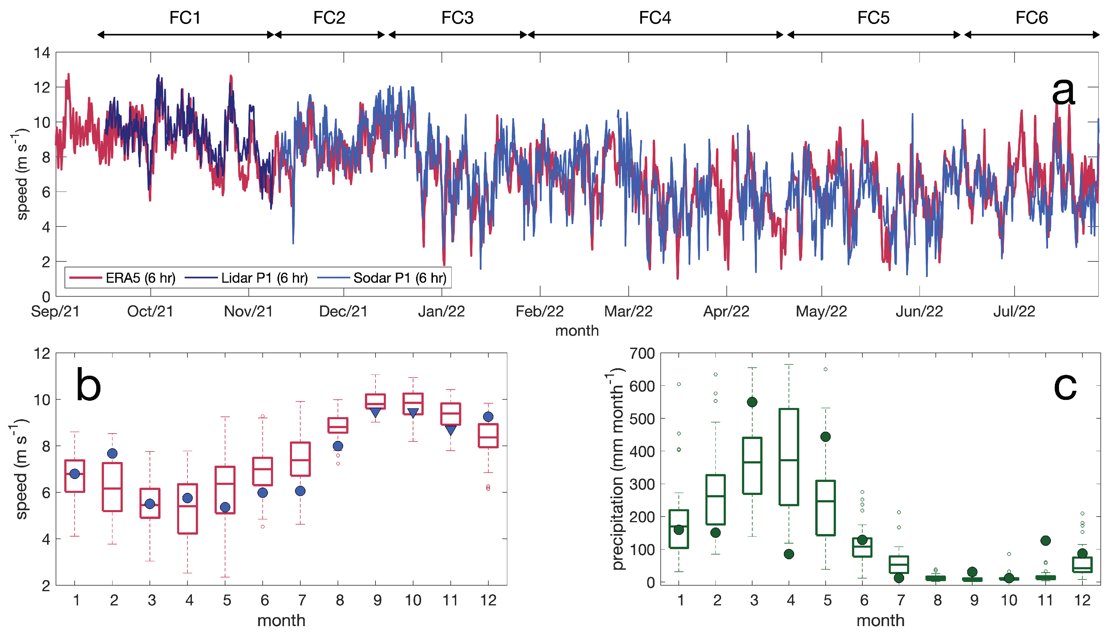
Figure 2. (a) Wind speed time series comparing ERA5 with observed winds derived from LIDAR and SODAR measurements at P1 location. All series are relative to the height of 100 m and averaged for a 6-hour resolution. A light red line indicates ERA5, dark blue represents the LIDAR and light blue the SODAR. Two-sided arrows on the top of the graph indicate the period of EOSOLAR field campaigns FC1 to FC6. (b) Wind speed climatology (1979–2021) at 100 m height derived from ERA5 monthly database. EOSOLAR observations are plotted as blue bullets (SODAR) and triangles (LIDAR). (c) Precipitation climatology (1979–2021) derived from ERA5. Bullets represent observations derived from micrometeorological towers. Box plot edges on panels (b,c) are the 25th and 75th percentiles. The central mark in each box represents the median. Whiskers extend to the most extreme data points not considered outliers. Outliers are plotted as empty circles. Although this article focuses on the field campaigns FC1 to FC6, up to 27 July 2022, data from August 2022 are included in panels (b,c) for completeness.
Energies 16 05555 g002
Figure 3. Atmospheric conditions during EOSOLAR field campaigns. Maps are organized from top to bottom covering, respectively, the field campaigns FC1 to FC6. The left panels display mean wind speed and direction at 100 m height above the surface. Right panels refer to accumulated precipitation in each field campaign converted to mm month 1 . Fields were constructed based on ERA5 Atmospheric Reanalysis hourly fields. Labels refer to Intertropical Convergence Zone (ITCZ), northeast (NE) and southeast (SE) Trade winds. A black dot indicates the study region. Table 2 lists the timing of each field campaign.
Energies 16 05555 g003
Figure 4. Time series of wind speed at the height of wind turbines (z = 100 m) derived from the LIDAR and SODAR wind profilers. A thin gray line illustrates the SODAR series at a 10 min time resolution. Thick red and blue lines, respectively, depict the LIDAR and SODAR averaged to 3 h time resolution. Panels refer to the EOSOLAR campaigns FC1 (top) to FC6 (bottom). Equipment locations are indicated in the legend of each panel. SODAR was installed on station P0 for FC1 but was repositioned to point P1 for all other campaigns. LIDAR started positioned on P1 for FC1 then moved to P0 for FC2. The equipment was reinstalled on points P2 to P5 for subsequent campaigns. In all panels, the x-axis is rescaled to represent the time covered for each campaign. Stations locations are indicated in Figure 1b.
Energies 16 05555 g004
Figure 5. Statistical distributions of wind speed and direction. All panels refer to winds at the height of 100 m above the surface, derived from LIDAR and SODAR measurements at the monitoring point P1 (see Figure 1b for location). (a) Histograms of wind speed. Each field campaign (FC1 to FC6) is depicted by different line colors. The gray shading represents the distribution considering all campaigns and histogram bins are 0.5 m s 1 wide. (b) Histogram of wind direction for each field campaign (colored lines) and the entire period of observations (gray shading). Vertical bars are 15° wide and indicate the direction from which the wind blows. All analyses are based on 10 min time resolution dataset.
Energies 16 05555 g005
Figure 6. Wind roses of each measurement campaign FC1 to FC6 at station P1. Direction bins have 5° increments and follow the meteorological convention, indicating the direction from which the wind blows. The radial distance indicates the percentage of occurrence of any particular direction, while the colors represent the intervals of wind speeds. A green shade indicates the coastline’s general orientation, considering a radius of 30 km from point P1 location.
Energies 16 05555 g006
Figure 7. Average vertical wind speed profiles. Panels depict station locations from P0 (right) to P5 (left). Line colors represent the field campaigns covered by observations. Station P1 is the reference station, with data coverage for all field campaigns. Colored symbols indicate the wind profiler. Squares are used to represent the LIDAR and triangles for the SODAR. A gray line is drawn on panels P0 and P2 to P5 to facilitate comparison, based on SODAR observations at P1 during the same field campaign. Station locations are indicated in Figure 1b.
Energies 16 05555 g007
Figure 8. Diurnal variability of wind speeds as a function of height, position and field campaign. Columns are organized according to field campaigns, with FC1 on the left and FC6 on the right. The top row refers to observations at the fixed station P1. Lower panels refer to positions P0 and P2 to P5. Line colors represent the height (m) of observations in reference to the surface. The title in each panel indicates the source of data (LIDAR or SODAR). Data loss on SODAR P0 (FC1) was substantial, so data above 130 m are not displayed. SODAR P1 (FC4) loss data for heights above 180 m.
Energies 16 05555 g008
Figure 9. Local wind hodographs, depicting the sea and land breeze interaction with the mean winds. Columns represent field campaigns, top row depicts station P1 and the bottom row stations P0 and P2 to P5. Winds were vertically averaged between 100 and 130 m. Hodographs were obtained by computing the mean wind vectors for each hour of the day. Winds at the peak of the land breeze (8 h) and sea breeze (16 h) are indicated by light blue and orange vectors, respectively. For other hours, vectors are omitted and their heads are indicated as bullets. A color scale represents the local time of observations. A thick black arrow indicates the mean wind vector for each campaign and location. Concentric gray circles indicate the magnitude of the winds with 2 m s 1 increments. A dashed line represents the general coastline orientation. Data loss on SODAR P0 was substantial so only data up to 130 m are displayed. SODAR P1 loss data are for heights above 180 m.
Energies 16 05555 g009
Figure 10. Roughness length z o and friction velocity u results obtained from the analysis of EOSOLAR micrometeorological towers. (a) Roughness length z o estimation, without accounting for atmospheric stability. (b) Same as (a) but accounting for the stability function ψ . Line colors on panels (a,b) depict the different terrain locations P0 to P5. (c) Diurnal variability of the mean friction velocity u computed for points P0 and P2 to P5. Line colors indicate the field campaign. (d) Same as (c), but for station P1.
Energies 16 05555 g010
Figure 11. Diurnal cycle of heat flux Q h b computed from EOSOLAR micrometeorological towers. Panels are organized vertically following the field campaigns, with FC1 positioned at the top and FC6 at the bottom. The left column illustrates the distributions for station P1, while the right column depicts the moving tower for locations P0 and P2 to P5. Q h b is given in W m 2 units and positive (negative) values indicate the surface heating up (cooling down) the atmosphere from below. Vertical bars illustrate ± σ standard deviations. Red and blue labels indicate, respectively, the percentage of occurrence of positive Q h b > 0 and negative Q h b < 0 fluxes. Labels on the left represent the statistics before dawn (0 to 6 h) and labels on the right indicate after dusk hours (18 to 24 h).
Energies 16 05555 g011
Figure 12. Frequency distributions of atmospheric stability based on Obukhov length L, estimated from micrometeorological tower data. Panels are organized vertically following the field campaigns, with FC1 positioned at the top and FC6 at the bottom. The left column illustrates the distributions for station P1, while the right column depicts the moving tower for locations P0 and P2 to P5. Limits used for stability classification are strongly stable ( 0 L 40 ), stable ( 40 < L 200 ), neutral ( | L | > 200 ), convective ( 200 L < 40 ), strongly convective ( 40 L < 0 ).
Energies 16 05555 g012
Figure 13. Frequency distributions of shear exponent computed from the LIDAR and SODAR wind profilers. Panels are organized vertically following the field campaigns, with FC1 positioned at the top and FC6 at the bottom. The left column illustrates the distributions for the fixed station P1, while the right column depicts the tower for P0 and P2 to P5 stations. Colors represent shear exponent classes following Wharton and Lundquist (2012) [36]: strongly stable ( α > 0.3 ), stable ( 0.2 < α 0.3 ), neutral ( 0.1 < α 0.2 ), convective ( 0.0 < α 0.1 ), strongly convective ( α 0 ).
Energies 16 05555 g013
Figure 14. Shear exponent average distributions as a function of wind speed (m s 1 ) and direction (degrees) at 100 m height. (a) Station P0 distribution based on LIDAR and SODAR observations obtained during FC1 and FC2 campaigns. (b) As in panel (a) but for station P0. (c) Station P2 distribution derived from LIDAR data for FC3. (d) Station P3 based on LIDAR data for FC4. Here, direction refers to the angle from which the wind blows. Average shear exponents are evaluated for a grid of 0.5 m s 1 × 6° bins, taking the average of at least 3 observations. A dashed line indicates the coastline’s general orientation.
Energies 16 05555 g014
Figure 15. Resource variability as a function of time, location and height. (a) Average wind speeds (m s 1 ) as function of field campaigns and the heights of 100, 130, 150, 200 and 260 m. (b) Capacity factor changes across field campaigns and the heights of 100, 130 and 150 m. The monitoring station P1 is illustrated with horizontal bars, whereas stations P0 and P2 to P5 are shown as a stem plot (vertical bars). Datasets are paired for same-time coverage. Heights with less than 50% coverage were not drawn.
Energies 16 05555 g015
Table 1. Equipment, auxiliary instruments, variables, measuring heights, sampling frequency and time resolution. AGL refers to above-the-ground level. Analyses using LIDAR and SODAR were carried out for the heights between 40 and 260 m.
EOSOLAR EquipmentAuxiliary InstrumentsVariablesMeasurement’s Heights
(AGL)
Sampling Frequency/
Time Resolution
SODAR
Model: MFAS/Scintec.
Wind profiler: speed, direction and turbulent intensity.39 levels:
20 to 400 m every 10 m.
4 s/10 min
LIDAR
Model: Windcube V2/Leosphere.
Surface Comet PTH T3311-L station (pressure, temperature and humidity).Wind profiler: speed, direction and turbulent intensity.20 levels:
40 to 200 m every 10 m.
220 to 260 m every 20 m
5 s/10 min
Micrometeorological tower 1Gill WindSonic 75 1405-PK-100 2D anemometer, RM Young 81,000 3D anemometer, Thermohygrometer HygroVUE10, Barometer Setra 278, Pluviometer TE525-L.Wind speed and direction, atmospheric pressure, precipitation, temperature and relative humidity.3.5 m (sonic 3D)
5, 7.5, 10 m (sonic 2D)
20 Hz/10 min
Micrometeorological tower 2Gill WindSonic 75 1405-PK-100 2D anemometer, RM Young 81,000 3D anemometer, Thermohygrometer HygroVUE10, Barometer Setra 278, Pluviometer TE525-L.Wind speed and direction, atmospheric pressure, precipitation, temperature and relative humidity.3.5 m (sonic 3D)
5, 7.5, 10 m (sonic 2D)
20 Hz/10 min
Table 2. Start and end dates, duration, equipment location and precipitation for EOSOLAR field campaigns. The LIDAR and SODAR microtower sets were moved in accordance with positions shown in Figure 1b. ★ FC4 was characterized by a large loss of SODAR data between 4 February 2022 to 6 March 2022, so that comparisons and statistics between LIDAR and SODAR were focused from 6 March 2022 to 18 April 2022.
Field CampaignBeginEndDaysEquipment Location Precipitation
FC114 September 20218 November 202155SODAR-microtower P0
LIDAR-microtower P1
47.7 mm
FC29 November 202113 December 202134SODAR-microtower P1
LIDAR-microtower P0
160.6 mm
FC315 December 202127 January 202243SODAR-microtower P1
LIDAR-microtower P2
170.4 mm
FC428 January 2022 (6 March 2022 ★)18 April 202280
(43 ★)
SODAR-microtower P1
LIDAR-microtower P3
728.6 mm
FC520 April 202213 June 202254SODAR-microtower P1
LIDAR-microtower P4
573.5 mm
FC615 June 202227 July 202242SODAR-microtower P1
LIDAR-microtower P5
74.9 mm
Table 3. ERA5 wind speed comparisons to observations. ERA5 data are derived from an offshore grid point located at 42.5° W and 2.5° S, while observations refer to wind speeds from station P1—a composed series of LIDAR and SODAR data. All wind speeds refer to a height of 100 m. The Pearson correlation coefficient (R), the root mean squared error (RMSE) and BIAS 1 N 1 N (ERA5 − observations) are indicated.
Time ResolutionRRMSEBIAS
1 h0.681.85−0.09
6 h0.771.46−0.09
12 h0.811.26−0.09
24 h0.880.94−0.09
Table 4. Wind speed mean, standard deviation (std), capacity factor (CF) and percentage of valid data (Perc) as a function of height and field campaign (FC1 to FC6). Equipment used and station’s position are indicated. Gappy data with less than 50% availability were omitted.
FC1FC4
LIDAR P1SODAR P0LIDAR P3SODAR P1
heightmeanstdCFPercmeanstdCFPercheightmeanstdCFPercmeanstdCFPerc
100 m9.281.670.6495.39.761.840.7081.2100 m5.212.060.1696.45.412.170.1861.2
130 m9.511.700.6795.39.511.730.6762.0130 m5.462.070.1896.15.742.210.2157.7
150 m9.641.720.6995.3---49.1150 m5.612.070.1995.85.922.240.2355.2
200 m9.881.760.7295.3---24.6200 m5.922.060.2294.6---48.5
260 m10.101.810.7495.3---9.9260 m6.222.060.2591.7---39.4
FC2FC5
LIDAR P0SODAR P1LIDAR P4SODAR P1
heightmeanstdCFPercmeanstdCFPercheightmeanstdCFPercmeanstdCFPerc
100 m9.632.010.6998.29.071.780.6294.8100 m4.771.890.1282.35.472.100.1892.9
130 m9.731.950.7098.29.391.760.6694.7130 m5.221.930.1679.25.872.170.2291.4
150 m9.791.910.7198.29.551.740.6894.3150 m5.491.950.1877.26.122.200.2589.8
200 m9.941.830.7398.29.811.680.7289.4200 m6.102.000.2371.86.642.370.3182.4
260 m10.101.780.7598.29.891.500.7371.2260 m6.642.050.2965.96.982.450.3569.2
FC3FC6
LIDAR P2SODAR P1LIDAR P5SODAR P1
heightmeanstdCFPercmeanstdCFPercheightmeanstdCFPercmeanstdCFPerc
100 m7.612.600.4399.37.752.490.4598.3100 m4.681.580.1080.25.911.740.2188.5
130 m7.842.590.4599.38.082.490.4997.9130 m5.121.610.1379.86.381.760.2587.1
150 m7.972.570.4799.38.232.470.5096.9150 m5.361.650.1579.66.681.810.2983.9
200 m8.262.540.5099.28.502.410.5488.6200 m5.791.780.2079.07.362.070.3868.6
260 m8.542.510.5398.68.562.290.5571.2260 m6.131.960.2375.7---45.6
Table 5. Wind speed statistics for station P1 at the height of 100 m. Weibull scale c and shape k parameters are listed, as well as the skewness (skew) of the distributions. The percentage of time that wind magnitudes U are below or above certain speeds is indicated. All analyses were based on a 10 min resolution time series.
Field CampaignckSkewU < 3U ≥ 10U ≥ 13U > 25
FC19.976.21−0.190.03%33.55%1.06%0.00%
FC29.775.92−0.590.58%31.06%0.43%0.00%
FC38.613.51−0.233.76%19.30%0.91%0.00%
FC47.272.970.047.81%5.17%0.07%0.02%
FC56.142.461.2713.59%0.96%0.12%0.11%
FC66.543.75−0.035.30%1.22%0.00%0.00%
all8.123.09−0.025.56%14.50%0.44%0.02%
Table 6. Roughness length z o statistics for field stations P0 to P5, computed from Equation (5) considering neutral conditions and the computation including the stability function ψ .
Neutral (mm)Stab (mm)
Stationmodemedianmodemedian
P00.951.380.951.19
P115.3313.7615.3313.56
P211.2611.0715.3312.83
P315.3314.3315.3315.15
P452.6853.2852.6843.65
P5335.56145.26246.46255.25
Table 7. Stability classification schemes based on the Obukhov length L (m) used in the literature and applied in this work. Convective and strongly convective classes are also referred to as unstable and very unstable, respectively. Columns are oriented from negative to positive L to facilitate comparison. Limits shown for neutral are considered near-neutral in some works, see text for details.
ReferencesNeutralConvectiveStrongly ConvectiveStrongly StableStableNeutral
Van Wijik et al. (1990) [69,70,71,72,73] L < −1000−1000 L < −200−200 L < 00 L 200200 < L 1000 L > 1000
Gryning et al. (2007) [35,75] L < −200−200 L < −100−100 L < −5010 L 5050 < L 200 L > 200
Warthon and Lundquist (2012) [36,74] L < −600−600 L < −50−50 L < 00 L 100100 < L 600 L > 600
Archer et al. (2016) [37] L < −500−500 L < −100−100 L < −55 L 100100 < L 500 L > 500
Sakagami et al. (2015) [29] L < −200−200 L < −50−50 L < 00 L 5050 < L 200 L > 200
this study L < −200−200 L < −40−40 L < 00 L 4040 < L 200 L > 200
Disclaimer/Publisher’s Note: The statements, opinions and data contained in all publications are solely those of the individual author(s) and contributor(s) and not of MDPI and/or the editor(s). MDPI and/or the editor(s) disclaim responsibility for any injury to people or property resulting from any ideas, methods, instructions or products referred to in the content.