1. Introduction
Excellent electrical strength, temperature resistance, and degradation resistance are all features of porcelain insulators [
1]. The overall dependability of the electrical system means that it has remained the primary power insulator since it was founded roughly 150 years ago. Ceramic insulators, however, corrode when exposed to highly corrosive conditions and high temperatures in coastal regions or coastal regions close to industry. The pin (galvanized steel)–cement interface has holes and fissures that increase its susceptibility to corrosion [
2].
Due to load stress and non-uniformity, the insulators closer to the conductor are more vulnerable to voltage stress. The local threshold fracture stress of the pores/crevices would be reduced, due to the corrosive aqueous species (aqueous chloride/hydrogen sulfide) being adsorbed on the surface of the pores/crevices at the pin–cement contact. In addition, the corrosive ions create local active–passive cell networks across the pin (galvanized steel)–cement contact by rupturing the local passive film within crevices and pores. The growth of the local deformation (pores/crevices) at the pin–cement interface is caused by the combined and synergistic interaction of mechanical (tensile stress) and chemical (corrosion reaction) forces applied by adsorbed corrosive species in a higher temperature environment (25–45 °C). The incident causes crack propagation throughout the insulator. As a result, the pin (galvanized steel)–cement contact’s localized deformations (micropore/crevice) are considered the epicenters of stress corrosion crack propagation [
3]. This predicament threatens the reliable and secure operation of electrical utilities. Therefore, surface modification and treatment techniques are needed for high-voltage insulators.
Power utilities commonly use traditional solutions, such as surface washing and periodic silicone grease coating, to combat these issues. However, these methods are time-consuming, expensive, and possibly environmentally damaging. A superhydrophobic, self-cleaning insulator surface seems to be a preferrable choice. Therefore, an insulator surface coated with superhydrophobic materials might be a workable and affordable substitute for current techniques [
2,
3].
One widely studied coating is the polydimethylsiloxane (PDMS)-based room-temperature vulcanized (RTV) silicon rubber coating. Field investigations have shown that RTV coatings can prevent leakage currents by developing PDMS chains on the insulator surface, forming a thin, non-conductive layer. However, these coatings have a maximum lifespan of around 10 years when exposed to high levels of pollution [
4,
5].
Researchers have explored alternative materials and methods to enhance insulator coatings’ properties. For example, a study conducted by Li et al. utilized a combination of 8 wt% nano silica and polyurethane to create a hydrophobic coating for porcelain insulators. Adding nano silica improved the hydrophobicity of the coating, while polyurethane enhanced its mechanical strength and resistance to UV radiation [
6].
Another approach investigated by Ma et al. involved the development of a sol-gel coating using tetra-ethoxy silane, perfluoro decyl-tri methoxy silane, ethanol, nitric acid, and hydrochloric acid. The resulting hydrophobic coating exhibited excellent self-cleaning ability and performance under light and medium pollution levels [
7,
8,
9].
However, it is essential to note that these discussed approaches primarily fall under the category of barrier coatings. While barrier coatings effectively protect insulators from corrosion and surface degradation, they have limitations due to poor interface bonding between the substrate and the coating. This drawback results in a weak interface, making the coatings less suitable for harsh circumstances where they must withstand extreme conditions [
9].
Superhydrophobic coatings have gained significant attention in recent years due to their exceptional water-repellent properties. However, their practical application in the industry faces challenges. Research conducted by Wang et al. highlighted the difficulties associated with superhydrophobic coatings, including complex production procedures, ineffective lab-scale application methods, and low mechanical durability [
10]. These challenges have hindered their widespread use in practical applications.
Further research is necessary to overcome the limitations of superhydrophobic coatings. Studies have been focused on comprehensively understanding the behaviors of these coatings under challenging conditions, such as exposure to corrosive agents, thermal stress, and mechanical stress. By thoroughly understanding their performance, researchers aim to develop improved production methods and enhance the mechanical durability of superhydrophobic coatings, thus making them more suitable for practical applications in various industries, including as insulator protection [
11,
12].
The wetting behavior of surfaces is a complex phenomenon that depends on various factors, including surface roughness, chemistry, and dynamic behavior. Advances in surface modification techniques and understanding of wetting behavior have led to development of novel materials for various industrial applications [
12]. The wetting behavior of surfaces is not only determined by surface roughness, but also by surface chemistry. Surface chemistry affects the surface energy and, hence, the wetting behavior of the surface. Surface modification techniques, such as chemical functionalization, plasma treatment, and coating deposition, can alter the surface chemistry and, consequently, the wetting behavior of a surface [
13]. Two primary regimes can describe the wetting behavior of rough surfaces. First is the Wenzel state, in which a water droplet permeates the surface’s characteristics and wets the entire surface. In the Wenzel state, a liquid droplet thoroughly penetrates the surface features, filling the valleys and grooves [
13,
14]. The liquid droplet spreads out, increasing the surface area in contact with the surface. In the Wenzel state, the droplet adheres to the surface structures, creating a solid interface between the liquid and the surface. The state is favored on smooth and hydrophilic surfaces with high surface energy, and the liquid can easily wet the surface [
14]. The second is the Cassie–Baxter state, where the water droplet is in contact with only the peaks of the surficial micro-nano features, and air pockets are trapped beneath the water droplets. In the Cassie–Baxter state, the droplet does not wet the surface features thoroughly, so it does not adhere to the surface. Due to the minimal resistance provided by the trapped air pockets, water droplets in the Cassie–Baxter state can roll readily, whereas, in the Wenzel state, the droplets adhere to the surface structures. The Cassie–Baxter state must be formed and maintained for a droplet to move across a surface [
14,
15].
The study conducted by Sanyal et al. focused on developing a CeO
2 conversion coating for insulator surfaces. The authors investigated the wetting properties of the coating and its ability to alter the surface energy of the insulator. The CeO
2 conversion coating demonstrated improved hydrophobicity, reducing the adhesion of water droplets and enhancing the insulator’s performance under wet conditions [
15].
Another research effort by the same researchers explored using a CeO
2–EPDM composite coating on insulators. The study investigated the corrosion resistance and mechanical durability of the coating. The CeO
2–EPDM composite coating exhibited enhanced resistance to corrosive agents and maintained its protective properties, even under mechanical stress. This coating design approach effectively prevented surface degradation and improved the insulator lifespan [
16]. These comprehensive investigations contribute essential insights into the potential of cerium-based coatings to augment the performance and longevity of insulators in varied operational conditions.
Thus, particular attention has been given to introducing a pioneering approach by infusing PFPE lubricating oil into a hydrophobized CeO2 composite coating, meticulously examining its sustained Cassie–Baxter state. This innovative coating design holds significant promise for enhancing the performance of insulators. Moreover, the performance of three cerium-based coating design approaches, including CeO2 conversion coating, CeO2–EPDM composite coating, and PFPE lubricating oil-infused hydrophobized CeO2 composite, has been thoroughly examined under various corrosive, thermal, and mechanical loads. Notably, the capability of these coatings to form and maintain the Cassie–Baxter state has been extensively evaluated.
2. Materials and Methods
The Korea Electric Power Corporation (KEPCO, Naju-si, Korea) provided the insulator specimens. All the chemicals, such as isopropyl alcohol (IPA), hydrogen peroxide (H2O2), cerium oxide (CeO2), ethanol (C2H5OH), acetic acid (CH3COOH), Krytox 157 FSL oil (PFPE), calcium hydroxide (Ca(OH)2), sodium chloride (NaCl) and sodium sulphate (Na2SO4) were procured from Merck, Seoul, Korea.
The conversion coating was developed in three steps: oxide growth, thickening of the oxide, and formation of the conversion coating. Cerium-based conversion coating is a type of conversion coating that is commonly used to improve corrosion resistance. The coating is applied by immersing the metal substrate into a solution containing cerium ions, which react with the metal surface to form a thin layer of cerium oxide [
15].
The oxide was produced by dipping insulator specimens for 30 min in a 250 mL acidic solution that contained H
2O
2 (2.5 mL) and HNO
3 (5 mL) [
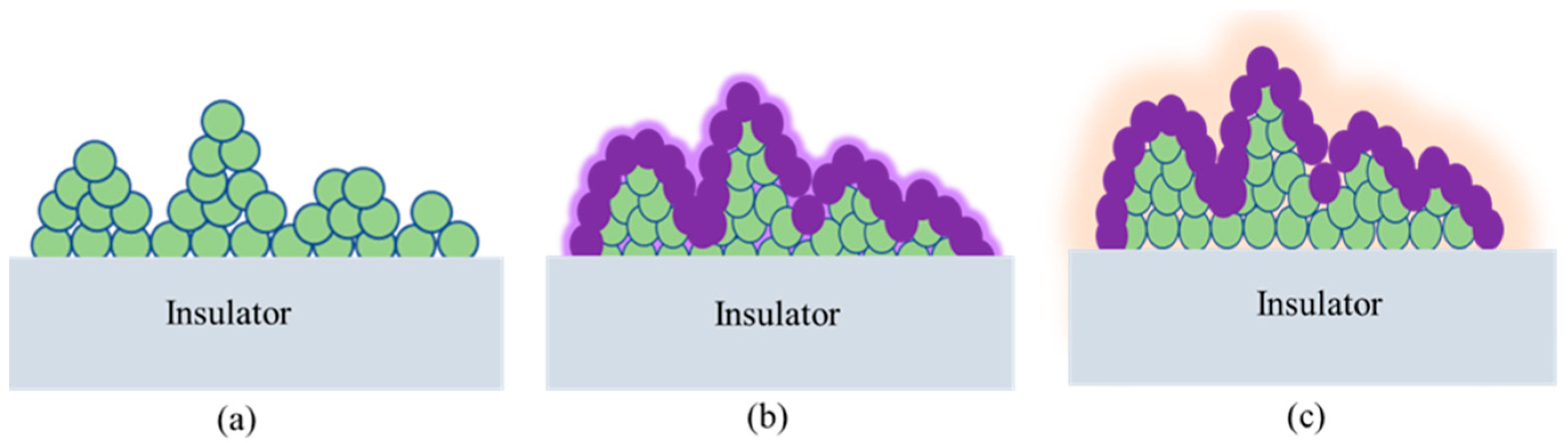
16]. The pH of the acidic solution was measured to be 3.5. The thickening of oxide was performed by immersing specimens in DI water for 30 min at 90 °C. The conversion coating film formed over illustrations by dissolving into 500 mL of 10,000–100,000 ppm CeO
2 coating bath, as shown in
Figure 1a [
15,
16]. To prepare cerium sol precursors, 10 gm of CeO
2 was dissolved in 10 mL of ethanol, 5 mL of acetic acid, and 5 mL of DI water. The prepared sols were agitated by ultrasonication for 1 h under 60 °C. The obtained composite was sprayed (3–5 times) on insulator samples, and dried at temperature for 3 h. Finally, EPDM was coated on insulator specimens by brush, cured for 5 h at 80 °C, and dried for 24 h at room temperature. The samples can be seen in
Figure 1b [
16].
The slippery lubricant-infused porous coating offers corrosion resistance and a non-stick surface to various materials. This coating is a porous material, typically a polymer, infused with a lubricating liquid. The lubricating liquid becomes trapped within the pores of the porous material, and is released under pressure.
Figure 1c illustrates the fabrication of a PFPE lubricating oil infused porous CeO
2 composite on an insulator surface. The hydrophobized CeO
2 composite was applied to the insulator surface (specimen 3) following the procedure described for specimen 2 in
Figure 1b.
The prepared composite was sprayed onto the insulator samples three to five times, and left to dry at room temperature for 3 h. Finally, a brush or spray was used to apply the PFPE lubricating oil onto the insulator specimens. Any excess PFPE lubricating oil was removed during the process. As a result, a PFPE-infused hydrophobized CeO
2 composite was successfully developed on the insulator surface [
16,
17]. The thickness of the coating can be observed in the micrographs shown in
Figure S1 and
Table S2. The thickness of the prepared composites T0, T1, and T2 are 30 μm, 30 μm, and 31 μm, respectively.
The thermo-mechanical aging of the insulator specimens was performed by fatigue testing machines manufactured by ZwickRoell (Ulm, Germany) for up to 500 h (250 cycles) by temperatures varying from −60 °C to 60 °C. All the samples were aged at constant conditions. The heating and cooling phases were of equal duration, and continued for 1 h each. Using a Phoenix 300 Touch (Surface & Electro Optics, Suwon-si, Korea), the water contact angle (WCA) and contact angle hysteresis (CAH) measurements were taken. Each measurement was performed three times. The drop volume used was 3 mL. The CAH was determined by subtracting the advancing contact angle from the receding contact angle—the alterations in WCA and CAH after thermo-mechanical exposure were investigated [
17].
The 5 prepared specimens of area 1 × 1 cm2 were then loaded into the scanning electron microscope (SEM) chamber manufactured by Thermos Fisher Scientific, which was maintained under vacuum conditions to facilitate surface morphology of samples. The accelerating voltage was considered as 10k.
The stress at the pin–cement junction was calculated by utilizing COMSOL software. The minimum load operating on the healthy insulator of 25,000 lbs was 100 kN. Tafel curves were measured during Gamry-made electrochemical workstation tests by sweeping the voltage from −0.6 to 0.6 V versus the open circuit potential at 1 mV/s. The open circuit voltage was maintained at equilibrium, while the frequency was changed between 0.01–100,000 Hz to determine the electrochemical impedance spectroscopy [
17,
18,
19].
Corrosive media was created by mixing 1 L of deionized water with 24.12 g of NaCl, 4.01 g of Na2SO4, 4.02 g of MgCl2, 1.20 g of CaCl2, 0.10 g of KBr, 0.03 g of H3BO3, 0.3 g of SrCl2, and 0.02 g of NaF.
3. Results and Discussion
The degradation process of the surface layer of insulators involves a combination of physical and chemical mechanisms that contribute to the deterioration of the insulator’s surface. This degradation can occur due to various factors, and is influenced by the specific conditions and environment to which the insulator is exposed. Physical degradation refers to changes in the surface characteristics of the insulator that occur without involving chemical reactions. These changes can include mechanical wear, erosion, abrasion, or surface cracking resulting from thermal stresses or mechanical forces. These physical factors can weaken the surface of the insulator and compromise its mechanical integrity [
19]. Chemical degradation, on the other hand, involves the interaction between the insulator’s surface and corrosive agents present in the environment. Corrosive substances, such as moisture, acids, salts, pollutants, or reactive gases, can chemically react with the insulator’s surface materials. This chemical reaction can lead to corrosion, oxidation, hydrolysis, or other chemical processes that result in the loss of material, formation of corrosion products, or alteration of the surface composition [
20].
Thermomechanical aging provides physical degradation of the samples. Thermo-mechanical aging is a process that involves subjecting a material to elevated temperatures and mechanical stresses for a specified period. Before evaluating functionalities, the specimens were exposed to thermo-mechanical aging to evaluate mechanical and chemical stability. Thermo-mechanical aging can simulate the effects of long-term exposure to high temperatures and mechanical stress, which can cause degradation and failure of the coating. By subjecting coatings to thermo-mechanical aging, researchers can assess the durability and effectiveness of these coatings under real-world conditions [
20].
The insulator specimens’ cement part represents more significant damage than other parts, as shown in
Figure 2a. The T0 and T1 specimens will expand and contract when exposed to hot and cold ambient temperatures, respectively. Samples T0 and T1 depict 5 µm and 1 µm broad crevices, respectively, after exposure to thermo-mechanical aging of 500 h (250 cycles), as shown in
Figure 2b–d. However, specimen T2 depicts no crevice opening after thermo-mechanical aging. This phenomenon can be explained as follows [
20,
21]. The CeO
2 conversion coatings, EPDM–CeO
2 composites developed on specimens T0 and T1, do not have crack-healing properties. Specimen T2 is a lubricating film that can flow towards the crack opening.
In contrast to T0 and T1, the EPDM–CeO
2 nano composite enriched lubricating film found in specimen T2 will heal the cement opening in the event of crevice formation [
20,
21,
22]. Inorganic oxide nanoparticles may cover the matrix’s interfacial fissures and significantly enhance mechanical properties, such as increased compressive strength, flexural strength, and higher fracture toughness. In addition to enhancing the interfacial transition zone, inorganic oxide nanoparticles can also improve the chemical properties of cement-based materials. The ability of these nanoparticles to fill interfacial fissures can lead to improved strength, toughness, and resistance to environmental and chemical degradation [
22].
The contact angle measurements of the insulator specimens were measured before and after thermo-mechanical aging. The T0, T1 and T2 samples show contact angles such as 70°, 160°, and 160.1°, respectively, before exposure to thermo-mechanical aging.
After exposure of 500 h (250 cycles), the contact angle of specimens T0 and T1 specimens represented reduced contact angles of 25° and 90°, respectively. Specimen T2 maintained a contact angle 160.1° [
22,
23,
24].
One possible reason is that specimen T0 does not exhibit hydrophobicity, which allows water to infiltrate inside cement microcracks [
22]. When exposed to higher temperatures, the moisture trapped within the microcracks evaporates, forming surface cracks in the cement. The reduction in contact angle observed in the specimen may be primarily attributed to this phenomenon. On the other hand, in the case of specimen T1, the initially trapped air within the micro-nano asperities created by the EPDM–CeO
2 composite helps to displace water droplets above the micro-nano features [
23]. This condition can be categorized as Cassie–Baxter’s regime of super hydrophobicity. Due to external stimuli, the Cassie air-trapping wetting state could be converted into the Wenzel state. Specimen T2 maintains non-wettability due to the healing properties of the PFPE-infused hydrophobized CeO
2 composite. The contact angle hysteresis measurements also align with the specimens’ contact angle measurement results. Specimen T2 shows lower contact angle hysteresis at 2.3°, thus maintaining super hydrophobicity [
24].
Further, the contact angle measurements state that the transition from Cassie to Wenzel occurs via a nucleation mechanism starting from the drop center, due to the surface degradation of specimen T1 [
23,
24]. The change converts specimen T1 from a fully non-wettable to a partially wettable surface. The specimen T2 maintains non-wettability due to the healing properties of the PFPE-infused hydrophobized CeO
2 composite. The contact angle hysteresis measurements also align with the specimens’ contact angle measurement results. Specimen T2 shows lower contact angle hysteresis at 2.3°, thus maintaining superhydrophobicity, as shown in
Figure 3 and
Figures S2 and S3 [
24].
Based on the surface deterioration results in
Figure 2, the stress analysis at the pin–cement junction for specimens T0, T1 and T2 were carried out using a 3D stationary mechanical simulation utilizing finite element analysis for three different coating techniques. The stress within each element is determined using mathematical equations that relate the deformation to the material properties of the element. These stresses are then used to calculate the overall stress within the structure or component, which can be used to determine whether it will fail under the given loading conditions [
23,
24]. Overall, the principle behind the calculation of stress by FEA is to use numerical methods to break down a complex structure or component into more specific elements that can be analyzed individually, then combined with the results to determine the system’s overall behavior [
24].
Figure 4 illustrates the finite element analysis in three dimensions for the three distinct coating processes with 5 mm, 1 mm, and 0.1 mm fracture openings under a 100 kN load. Insulator specimens coated with PFPE-infused hydrophobized CeO
2 composite had no crevice openings. The simulation was performed by considering the ignorable micro-crack size of 0.1 µm, to understand the effect of crevices at the pin–cement junction. Due to the broad opening of 5 µm, the stress at the pin–cement junction of insulators coated with CeO
2 was highest, 450 MPa. In contrast, the insulators coated with PFPE-infused hydrophobized CeO
2 composite showed the lowest stress of 170 MPa at the pin–cement junction. The critical zone of the insulator with the highest stress is found at the pin–cement intersection [
24].
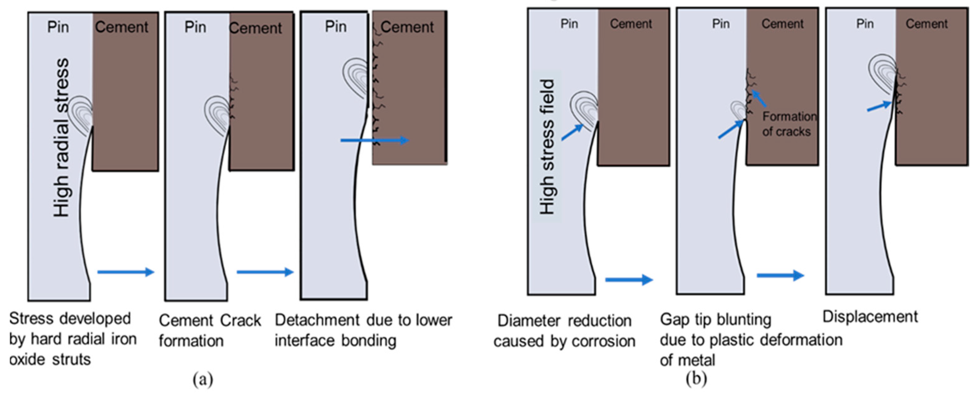
The micro crevices in the pin–cement interface can intensify the stresses and lead to pin failure. Due to plastic deformation at the pin–cement junction, the pin–cement stress can also cause necking of the circumferential cross-section of the pin, as shown in
Figure 5. Necking is a type of deformation that occurs when a material undergoes a tensile load beyond its yield strength. The material begins to deform and narrow in the cross-sectional area, causing a reduction in its overall strength. As necking progresses, the cross-sectional area of the pin decreases, resulting in an increased local stress concentration at the necked section. This can cause further plastic deformation, potentially leading to fracturing of the pin at the necked section [
25].
The polarization curve can provide information about the corrosion behavior of a material, including the corrosion potential, corrosion current density, and passivation potential. The material’s corrosion resistance under different conditions can be studied by analyzing the polarization curve [
23,
24,
25]. The corrosion resistance properties of the specimens can be evaluated after exposure to corrosive media, as shown in
Figure 6. The corrosion current density (I
corr) and the corrosion rate for T0 specimens are the highest (2.89 × 10
−6 A/cm
2, and 4.41 × 10
−2 mm/Y, respectively) over T1 and T2, as shown in
Figure 6a. The T0 specimens utilize CeO
2 conversion coating for corrosion protection. Due to a lack of hydrophobic performance, the barrier layer may disintegrate in excessively severe conditions. Local corrosion takes place in the area where the barrier layer dissolves [
24,
25]. Similarly, T1 specimens show a lower corrosion rate and I
corr (0.22 × 10
−2 mm/Y, 0.9 × 10
−6 A/cm
2) than T0.
The air pockets present in micro-nano asperities of the EPDM–CeO
2 composite might not allow the corrosive fluids to encounter the EPDM–CeO
2 composite. However, under extremely harsh conditions, the corrosive fluids may penetrate the asperities of the EPDM–CeO
2 composite, leading to preliminary corrosion [
23,
24,
25,
26,
27]. In the case of specimen T2, due to the presence of a slippery lubricative top film, corrosive fluids might not be allowed to come in direct contact with the PFPE-infused hydrophobized CeO
2 composite.
Due to the phenomena, T2 specimens show the lowest corrosion rate and I
corr (0.3 × 10
−3 mm/Y, 1.2 × 10
−7 A/cm
2), as shown in
Table S1. The Nyquist plots and Bode plots in
Figure 6b–d exhibit the highest corrosion resistance for T2, and align with previous findings.
4. Conclusions
The PFPE lubricating oil-infused porous CeO2 composite (T2) showed the best performance among the three coating approaches evaluated on insulator surfaces.
After 500 h of thermo-mechanical aging, T2 specimens had no crevice opening, while the T0 and T1 specimens had crevices of 5 µm and 1 µm, respectively.
Before aging, the contact angles were 70° for T0, 160° for T1, and 160.1° for T2.
After aging, the contact angles were reduced to 25° for T0, 90° for T1, and 160.1° for T2.
T0 specimens had the highest corrosion current density (2.89 × 10⁻⁶ A/cm2) and corrosion rate (4.41 × 10⁻² mm/year).
T2 specimens exhibited the lowest corrosion rate (0.3 × 10⁻³ mm/year) and corrosion current density (1.2 × 10⁻⁷ A/cm2).
Based on these results, the PFPE lubricating oil-infused porous CeO2 composite (T2) is the most suitable coating approach for insulators exposed to extreme conditions.


