Article

Optimal Demand Response Using Battery Storage Systems and Electric Vehicles in Community Home Energy Management System-Based Microgrids

1
Department of Electrical and Computer Engineering, International Islamic University Islamabad, Islamabad 44000, Pakistan
2
Department of CIT, The Applied College, King Abdulaziz University, Jeddah 21589, Saudi Arabia
3
Department of Electrical Engineering, Bahria University, Islamabad 44000, Pakistan
4
Faculty of Information Technology & Computer Science, University of Central Punjab, Lahore 54000, Pakistan
5
Center for Advanced Studies in Energy, National University of Science and Technology, Islamabad 44000, Pakistan
*
Author to whom correspondence should be addressed.
Energies 2023, 16(13), 5024; https://doi.org/10.3390/en16135024
Submission received: 22 May 2023 / Revised: 21 June 2023 / Accepted: 22 June 2023 / Published: 28 June 2023
(This article belongs to the Section A: Sustainable Energy)

Abstract

:
Demand response (DR) strategies are recieving much attention recently for their applications in the residential sector. Electric vehicles (EVs), which are considered to be a fairly new consumer load in the power sector, have opened up new opportunities by providing the active utilization of EVs as a storage unit. Considering their storage capacities, they can be used in vehicle-to-grid (V2G) or vehicle-to-community (V2C) options instead of taking power in peak times from the grid itself. This paper suggests a community-based home energy management system for microgrids to achieve flatter power demand and peak demand shaving using particle swarm optimization (PSO) and user-defined constraints. A dynamic clustered load scheduling scheme is proposed, including a method for managing peak shaving using rules specifically designed for PV systems that are grid-connected alongside battery energy storage systems and electric vehicles. The technique being proposed involves determining the limits of feed-in and demand dynamically, using estimated load demands and profiles of PV power for the following day. Additionally, an optimal rule-based management technique is presented for the peak shaving of utility grid power that sets the charge/discharge schedules of the battery and EV one day ahead. Utilizing the PSO algorithm, the optimal inputs for implementing the rule-based peak shaving management strategy are calculated, resulting in an average improvement of about 7% in percentage peak shaving (PPS) when tested using MATLAB for numerous case studies.

1. Introduction

Ever since the deregulation of electric power industry, smart grids have gained significant attention, as they provide a complete framework for effective electricity utilization. The smart grid framework encompasses all smart devices that generate and store electricity and also allows consumer participation to fulfill energy requirements for smart homes and smart grids. Smart grids aim to optimize electricity distribution and consumption by incorporating all smart appliances that generate and store electricity, enabling consumers in households to meet their desired load requirements [1,2]. Consumer households have electric vehicles (EVs), which are end-user smart appliances that can operate either as a load (when charging) or as a resource (when fulfilling vehicle-to-grid (V2G) or vehicle-to-community (V2C) demands). Some EVs have enough power to run multiple smart homes.
Microgrids (MGs) are a subset of smart grids that use different energy management techniques and provide dual benefits to the power system. Home energy management systems (HEMS) contribute to the steadiness and consistency of MGs by enabling residential consumers to use their domestic appliances in a more efficient manner [3]. HEMS is an important component of smart grid control systems, given the significant demand for electricity in the residential sector [4]. Demand response techniques allow residential consumers to shift the peak load to off-peak periods, thereby reducing the peak power demand and bringing it closer to the average power demand [5]. One potential solution for managing peak power demands in HEMS is load scheduling using demand-side management techniques [6,7]. Recent studies have explored cluster-based load scheduling optimization approaches at the microgrid level; however, they do not take into account the preferences of consumers at the appliance level [8,9].
The grey wolf and crow search optimization (GWCSO) algorithm was employed by Waseem et al. to reduce electricity cost (EC) and the peak-to-average ratio (PAR) [10]. However, their technique limited the scope of the GWCSO algorithm since they only considered HVAC loads for scheduling. Additionally, their models did not have a mechanism for managing large amounts of data from different communities. Aziz et al. presented a large population-based power scheduling methodology that employed a static clustering-based approach to manage residential consumers in different communities. However, their approach assumed that all appliances in the entire population had the same characteristics and belonged to a similar class of consumers, i.e., homogeneous load assumption [11,12]. Considering community-based population, a non-homogeneous load scheduling approach integrated with dynamic appliance clustering was proposed [7]. Improvement in PAR and EC is attained to some extent while leaving some peaks behind. To overcome this limitation, an alternative approach for further adjusting the demand profiles is to use an algorithm based on energy storage systems, such as peak shaving, as proposed by authors in references [13,14]. These studies do not take into account the impact of weather fluctuations on consumer behavior while considering their preferences. The highlighted studies indicate that load scheduling and peak shaving should be implemented in a more realistic scenario that incorporates weather condition-based changes in consumer preferences as well as the incorporation of energy storage systems and EVs.
Peak shaving is regarded as a vital application for both grid operators and end users. Grid operators use peak shaving for balancing supply and demand, yielding a greater load factor and more economical generator operation. Grid-connected battery energy storage (BES) systems and EVs can be utilized for peak shaving [15]. Charge/discharge schedules for BES systems are controlled using various techniques, including rule-based and genetic algorithms, and dynamic programming [16,17]. Rule-based methods execute instructions based on an initial data set and if–then statements [18]. However, these algorithms are not as efficient as optimization methods. The authors drew a contrast between rule-based peak shaving techniques and optimization methods in [19,20,21]. Several optimization-based techniques exist in the literature that incorporate demand and feed-in limits. Regarding peak shaving, the feed-in limit and demand limit are defined as the maximum power that can be injected into or extracted from the grid, respectively. The authors discussed the set demand limit in [22,23] for peak shaving using the battery controller, but they did not discuss the feed-in limit. For peak shaving applications, flexible daily management along with effective PV energy consumption is considered for a fixed demand ceiling [24]. Some studies consider only the dynamic feed-in limit, while others consider only the demand limit [25]. Vedullapalli et al. investigated peak shaving with BES optimal schedules and dynamic demand restrictions [26]. However, feed-in limitation is ignored in this study. In reference [27], both feed-in and demand powers were considered while conserving flexible daily management. In addition, they proposed an effective rule-based peak shaving management strategy considering a single household and determined the optimal inputs for the proposed technique [27]. The literature review suggests the implementation of peak shaving in a more practical scenario, incorporating distributed energy resources, such as EVs.
O. erdinc et al. proposed a novel HEM system based on a multiple integer linear programming (MILP) model that evaluates the DR strategy based on multiple operational factors: a small-sized (four people) distributed renewable energy generation system, dynamic pricing, and the vehicle-to-home (V2H) and V2G modes of EV and ESS [28,29]. Using the price signals from the load service entity (LSE), self-owned energy production sources (EV, ESS and photovoltaic (PV)), load-consuming smart appliances and the consumer preferences, the HEM system controls the smart household operations with the underlying objective of minimizing the total daily electricity costs. The cost is defined as the difference between the price of purchasing energy from the grid to the price of selling energy back to the grid. Both the prices vary with time. The concept of vehicle-to-everything (V2X) technology is gaining traction in the automotive industry, including electric vehicles (EVs). V2X refers to the communication and interaction between vehicles and various elements in their environment, such as other vehicles (V2V), infrastructure (V2I), pedestrians (V2P), and the grid (V2G). The concept of vehicle-to-everything (V2X) technology, including its application in electric vehicles (EVs), is still undergoing testing and refinement to achieve more improved results. While the idea of V2X has gained attention and shows promise, its widespread implementation and practicality in real-world scenarios are still being explored [30,31,32].
Based on the above highlighted limitations of energy management systems, an optimal demand response-based community energy management system exploiting the battery storage system and electric vehicles is proposed. An algorithm for load scheduling is utilized in a community architecture, followed by an optimal peak shaving scheme integrated with an energy management strategy to cater to day-to-day needs. The proposed HEMS controls the smart household operations with the underlying objective of minimizing the peak utility grid power (PUGP) and percentage of peak shaving (PPS). The energy is transferred in the priority of PV first, ESS second and EV last. Resources are selected once the previous ones completely or partially consumed based on the availability. An appropriate time granularity is selected based on the ratio of hour to the selected time. One of the constraints of the model is the balancing of power. According to this, the electricity needs of a residence, and charging needs of EV and ESS are met by either the grid or by a combination of energy obtained from PV, ESS and EV. Using the model, limits of power extraction and injection to the grid, charging and discharging duration, and limits of EV and ESS, etc., can be set. The proposed strategy offers enhanced performance for microgrids in community architectures. The load is heterogeneous due to variations in the power ratings of consumer appliances and diverse user preferences belonging to different classes. This strategy employs a demand response-based approach to schedule controllable appliances (CAs) based on user preferences, while taking into consideration multiple types of consumable appliances commonly found in households. Each class considers its own set of PV installations. In order to accommodate the seasonal variations in consumer behavior, the study examines different parameters of CA usage for summer and winter as shown in Table 1.
This article presents the following contributions:
  • The model was tested on a residential community consisting of 40 houses and contained a range of CAs. The study employs community consideration with various classes of consumers. Ten percent of the higher-class community is assumed to consider electric vehicles rated as 70 kWh battery rating Chevy Volt with a charging station of 10 kW power limit. A BES of 132 kWh is also considered.
  • A load scheduling and optimal rule-based peak shaving algorithm is proposed that incorporates BES, PV systems, and EV. The peak shaving algorithm takes into account both the dynamic demand and everyday feed-in limits.
  • A rule-based control algorithm considering flexible daily management is proposed that provides schedules for charging and discharging EV and battery for peak shaving of the utility grid power. The algorithm also takes into account the day’s feed-in limits and demand, which correspond to limited feed-in powers and utility grid demand.
  • The PSO algorithm is employed to obtain the optimal inputs for the suggested rule-based peak shaving management, which is aimed at reducing energy consumption from the utility grid.
The remaining article is structured as follows. Section 2 describes the considered system. Section 3 presents the load scheduling control scheme. Section 4 discusses the optimal peak shaving approach, which includes a discussion of the BES operational modes in Section 4.2, the proposed method of input determination in Section 4, the suggested rule-based peak shaving management approach in Section 4.4 and estimation of optimal inputs in Section 4.5. Section 5 presents the simulation results followed by Section 6, which concludes the whole article.

2. System Description

The framework offers the real-time monitoring of energy consumption and power rates, allowing the consumers to adjust their usage and control their bills, forming a dynamic demand response (DR) strategy for effective energy consumption. For instance, charging an EV and BES during off-peak times or discharging at peak time. The utility aims to achieve reduced peaks in the load profile that benefits the consumer by reducing lowest daily electricity costs. The primary objective of demand response-based HEMS is to reduce PAR and PUGP to benefit utility as well as customers in terms of reduced cost. This paper proposes a community-based system architecture compatible with MGs. The proposed scheme is implemented in a community that is part of one of the many MGs connected to others. The substations receive the demand response tasks from the electricity supply and then disseminate the information to their respective communities. Figure 1 illustrates the framework of the community-based scheme for a single community utilizing HEMS in smart grids. To achieve a load profile with reduced PAR, the proposed scheme employs a demand response-based HEMS that utilizes optimal load scheduling (LS). The remaining peaks in the load profile are addressed through dynamic demand and feed-in limits-based optimal peak shaving (OPS). The target of the OPS is to achieve reduced PUGP and improved percentage peak shaving (PPS).
The model takes into account different user preferences from various classes, resulting in non-homogeneous load demand. The study considers two types of load demand profiles: summer and winter profiles. Residential consumers tend to use certain appliances more frequently during specific seasons. For example, air conditioners are not generally used for heating in winters but more frequently used for cooling in summers. This trend is due to increased sunlight utilization and completing most tasks during the day.
As a result, the peak load demand hours tend to fall between 9:00 and 12:00 during winter and 20:00 and 23:00 during summer [27]. In winter, clothes dryers and electric heaters are utilized more frequently. However, during hot summer weather, water pumps and automatic washers are more commonly used due to the need for frequent clothes changing and bathing. Thus, these appliances usually work with regular tap water during summers rather than hot water. Moreover, dishwashers can function with normal tap water during summer but depend on hot water during winter to eliminate greasiness from utensils. For rice cookers, it is assumed that LCS, MCS, and UMCS have three meals per day, while HCS may have a different eating pattern. During winter, LCS may have three meals a day since they wake up early in the morning; however, this may not be the case during summer. These details are presented in [27] and are reflected in the load demand profiles. Table 1 shows that clothes dryers are marked as “not applicable” for LCS during summers. Additionally, electric vehicles are also taken into account, with different arrival and departure timings depending on seasonal changes. For example, during the summer, EVs leave for work at around 9:00 h with a lunch break around 2:00 to 3:00 h. During the winter, HCS begins the day a bit late, leaving for the office at around 11:00 h. Lunch is generally skipped, with an arrival time of around 6:00 h. We assumed that only 20% of HCS has EVs in use due to affordability issues; therefore, two EVs are considered in our community of 10 houses from HCS as shown in Table 1 and Table 2. The typical usage parameters for different classes of consumers in winter and summer are provided in [7], Table 1, considering all the aforementioned factors. The study includes an examination of communities comprising 40 households, with an equivalent number of homes from each consumer class during both summer and winter seasons. During summer, the peak load amounts to 35.94 kW, while during winter, it is 33.89 kW.

3. Optimal Load Scheduling (OLS)

An optimal load scheduling scheme for a domestic community for CAs is presented in this section. Modified inclined block rate (IBR) pricing and real-time electricity price (RTP) schemes are utilized. The suggested approach can be implemented in an actual system with specific adaptations.

3.1. Usage Patterns of Controllable Appliances in Residential Settings

The involvement of consumer choices in the scheduling process is achieved by considering various time parameters, such as the activation time slot. To cater to user preferences, the time parameters include the activation time slot (ATS) t a k , starting time for the operation of appliance (AST) α a k , the appliance operation end time (AET) β a k , time length of the appliance operation (ATL) l a k . The time interval for appliance operation is given by the range α a k , β a k which is the valid time interval for CA scheduling with a power rating of x a k .

3.2. Final Objective of Load Scheduling

To perform a more comprehensive analysis of the load demand and consumption patterns throughout the day, each hour is divided into 10 min time slots, resulting in 144 time slots of a day denoted by τ   ϵ   T , where T is a set of integers ranging from 1 to 144 [33].
The set of CAs is denoted by A . Each house comprises 16 devices; let a belong to the set {1, 2, …, 16}. Let a k be an element of the set A . It is assumed that P a k represents the scheduling vector, representing the utilization of power with a dimension of 1 × 144 ,
P a k [ p a k 1 , p a k 2 , , p a k 144 ]
The kW power consumption value for the ath appliance belonging to kth house is denoted by p a k τ . The per hour power consumption values are divided by six to generate per time slot values. The assumption of values for power utilization for each appliance are based on the values provided in Table 2.
The activation slot for the ath appliance of kth house is represented by t a k . After the computation of t a k , the power utilization scheduling vector for the ath appliance of the kth house is determined. Given that α a k , β a k , and l a k are all known, t a k should lie between α a k and β a k l a k . Therefore, the denotation of the modifiable parameter t a k is given as
t a k ϵ α a k , β a k l a k
By utilizing PSO, we can determine the optimal t a k allocation for each household in the community, which results in a decrease in EC and PAR. The user preferences provided by the customers help in deciding the initial value for optimization denoted by α a k . The cost function to minimize the electricity cost is then saved, and the best particle location (pbest) is adjusted.
To fulfill the constraint given in Equation (2) for the ath appliance and kth house, it is necessary to compute the optimal value of ATS for each CA. The optimal ATS values for all CAs are stored in a variable vector t a 1 k , t a 2 k , t a i k . Using these optimal ATS values, the scheduling matrix of the power utilization by all CAs can be formulated as shown in the expression as
P = p   |   p a i k τ = x a i k 6 , a i k ϵ   A , τ ϵ t a i k , t a i k + l a i k p a i k τ = 0 , a i k ϵ   A , τ t a i k , t a i k + l a i k
The matrix P contains rows representing the power consumption schedule for each individual appliance. The column indices are specified by τ . τ t a k , t a k + l a k represents that τ ϵ T , however, does not fall within the range t a k , t a k + l a k . To compute the vector P scd , which represents the scheduling of total power utilization, the respective matrix column vectors are summed up:
P scd = p scd p scd τ = P τ , τ ϵ T
P τ denotes the τ th column in the power utilization scheduling matrix in (4). When formulating the objective function for the power utilization scheduling problem in a single residence, the expression is as follows:
m i n i m i z e EC P scd s . t . t a k ϵ α a k , β a k l a k
where
EC P scd = τ = 1 144 rtp τ . p scd τ
The price of electricity during the τ th time slot is represented by rtp in Equation (6). To minimize the EC shown in the Equation (6), an optimization strategy can be employed.

3.3. Formulation of DHEMS

The dynamic home energy management system (DHEMS) algorithm is expected to allocate such an α a k to the CAs of various houses so that they operate in time slots that have the lowest electricity prices. Therefore, to ensure that the appliances of different houses have their α a k in the time slot with the least expensive electricity price in comparison to the subsequent intervals, scheduling methods coupled with IBR strive to shift the t a k values of all households towards that particular slot. However, IBR prevents the PUP of each dwelling from crossing the required level. Even then, the accumulation of appliances t a k around the lowest electricity price can cause a PUP peak in the general community, ultimately affecting the entire power grid. Therefore, to optimize ATS for all appliances, a power scheduling methodology is required that can scan the surrounding area. The problem at hand is effectively tackled by the proposed algorithm, which incorporates appliance clustering within a dynamic clustered home energy management system (DHEMS).
It is anticipated that the utility will allocate demand response tasks specifically to the substations, which will then communicate the information to the corresponding communities they serve. To analyze non-homogeneous loads, the division of the community, which consists of 40 houses, results in 4 distinct classes: LC, MC, UMC, and HC consumers. The consumers from these classes have their distinct consumer choices depending on their daily routines as shown in Table 1. Table 2 exhibits the power ratings utilized for CAs across all four classes. A randomly generated one-day load profile is subjected to particle swarm optimization (PSO) to determine the optimal clustering set from various combinations involving C1, C2, and C3 as depicted in Figure 2. Both uniform and non-uniform cluster sizes are considered when varying C3 from 2 to 7 clusters per community [12]. C1 determines the community size under each class of consumers. It is assumed that each class consists of 10 houses. Consequently, each class is divided into 2 communities, each comprising 5 houses. After being classified according to C2, the CAs are placed into their respective C3 clusters. Based on the optimal value of C1, each community comprises 5 dwellings. The sorting parameter chosen under C2 is AET. In each community, C3 designates the number of CA clusters which is set to 5 as determined by the optimal value based on C1.
The algorithm developed for load scheduling of the CAs is applied to the formulated data. The algorithm initiates by organizing the dwellings into groups of communities based on the criterion of C1. The houses are dynamically grouped into communities based on the PAR of each cluster. Within each house, the 16 appliances are divided into 5 clusters within each dwelling, based on their respective AST and AET. The maximum PAR is computed for all 5 clusters, and all dwellings are subsequently ranked based on this value. Given that each community consists of 5 houses, the lower class comprises 2 communities with a combined total of 10 dwellings. Each of the 3 other classes consists of ten dwellings, resulting in 2 communities per class. Therefore, there are a total of 80 appliances in a community that consists of 5 dwellings, which is equivalent to 5 × 16 .
The sequence of steps involved in DHEMS is explained below.
Step 1: The entire population is divided into four classes, each having an equal number of houses.
Step 2: The population is sorted using a staggered set of houses, which ensures that the houses are organized in a way that results in descending PARs within each cluster.
Step 3: The criterion for the best clustering is chosen.
Step 4: Appliances are categorized by neighborhood using C2
Step 5: Each community’s appliance cluster number is determined using C3.
Step 6:The parameters t a k belonging to the current cluster are set within the range α a k , β a k l a k , and step 4 is repeated for all clusters. The groups of t a k are used as particles.
Step 7: The fitness for each cluster is computed by analyzing the EC and P cc .
Step 8: After updating particles’ positions and velocities, pbest and global best (gbest) are updated if the fitness of the new particle is superior to that of the previous one.
Step 9: If the termination criterion is not met, we go to step 6.
Step 10: We stop once the full population has been scheduled.
Step 11: Steps 8–11 are repeated until the scheduling of all of the communities is achieved.
The overall objective of power scheduling is formulated as follows:
m i n i m i z e EC P c c s . t . t a k ϵ α a k , β a k l a k
E C P cc = k ϵ C h a ϵ C c τ = 1 144 rtp pc τ . p a k τ
In this context, the term EC ( P c c ) refers to the overall electricity cost calculated based on the PUP for the cluster of the currently scheduled community, denoted as P c c . In the given context, the symbol rtp pc τ represents the electricity rate for the τ th time slot. Furthermore, p a k τ denotes the power rating of the kth house’s ath appliance for the same time slot. C h represents all the houses in the current community, while C c denotes the current cluster. Therefore, the proposed algorithm’s objective function is to reduce the total consumer EC associated with power consumption. To keep the PAR under control, the modified IBR is implemented across the entire community, which is further divided into smaller communities.
The application of the proposed technique shows reduction in PAR in contrast to the actual load demand. However, despite the reduction, there are still some existing or emerging peaks that suggest the potential for further optimization through the use of an optimization scheme. To address these remaining peaks, we introduce a rule-based OPS control approach utilizing the PSO algorithm presented in the following section.

4. Optimal Peak Shaving (OPS)

A residential community system connected to the grid is illustrated in Figure 1, which shows an OPS proposed for MG connected to a utility grid, utilizing a community-based HEMS architecture. The MG system consists of a PV source, BES, EV and consumer loads. Considering the grid as a power source that can both provide and absorb energy, the power balance equation can be defined at the point of common coupling (PCC), while ignoring the system losses as
P gd ( t ) + P pv ( t ) + P bat ( t ) + P E V ( t ) = P LD ( t )
In (9), P gd denotes the utility grid power. P pv , P bat , P E V and P LD denote PV, battery, EV and load demand powers all in kWs. t represents the time interval, which is [ ( t 1 ) × T C , t × T C ] , where T C is the duration of a time slot and is equal to 10 min. Note that P gd is assumed to be the load scheduled output of the OLS scheme. Therefore, from now on, the term P gd refers to the load scheduled output of OLS that requires peak shaving using distributed energy resources, such as PV, BES and EV.

4.1. Distributed Energy Resources

In this study, PV power source, BES and EV are used as OPS control stage resources. The EV chosen for the study has a Chevy Volt battery rating of 70 kWh and is equipped with a charging station that has a maximum power limit of 10 kW. It is assumed that the same power limit is applicable for discharging operations in both V2G and V2C modes. Charging and discharging efficiencies are considered to be 0.95. The initial EV battery energy is assumed to be 35 kWh (50% state of energy) when the EV arrives at home, and the lower limit of the EV state of energy is restricted to about 20 kWh (30% state of energy) to prevent deep discharging. This limit is based on recommendations from [34], which suggest battery users to not extract more than 80–90% of the available capacity at any time.
In this study, the ESMAP Tier1 Meteorological Station in Islamabad, Pakistan, is used to obtain irradiance values for the PV system. Trina solar modules [TSM-320 PD14] with 17.5% efficiency, a size of 1.9 × 0.9   m 2 , and a power output of 320 W are used for the rooftop PV system. Consumer surveys in Pakistan indicate that low power consumers in LCS use around 150 units/month, while MCS consumers use 250 units/month without AC. UMCS consumers with 1 ton AC consume 500 units/month, while HCS consumers consume 750 units/month with 2 tons AC [35]. Based on these facts, we calculate the units for each community/day and for each class, which results in 250 units for LCS, 400 units for MCS, 800 units for UMCS, and 1250 units for HCS [36]. Each community has locally generated PV in various houses, with LCS having 2%, MCS having 4%, UMCS having 6%, and HCS having 8% of PV installation. A 15 kW PV system is installed, where LCS, MCS, UMCS and HCS have 300 W, 1.3 kW, 1.5 kW and 3.2 kW, respectively. For peak shaving, a 240 V, 600 Ah battery bank is selected.

4.2. Operating Modes of BES

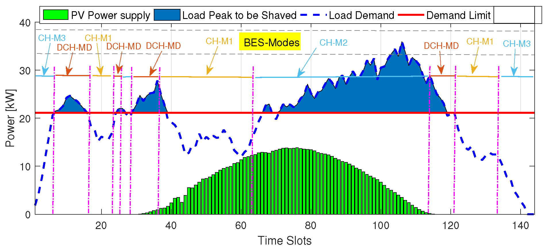
The demand limit P d l can be enforced for P g d ( t ) to be restricted within the limit, with the help of the considered EV, battery, and PV source. Figure 3 depicts the BES operating time slots for average PV power and load demand profiles. In the event of the presence of a PV source, four modes of operation are available to restrict P g d ( t ) to P d l using a BES and EV.
(1)
Discharging Mode: [DCM] When the load demand exceeds the demand limit, and the PV source and EV are unable to provide the required power, the discharge time t dch occurs, i.e., P LD t > P d l & &   P pv t P LD t P d l . The EVs are also not available to support the grid due to the nearly expected departure or departed already. The symbol “&&” represents the logical AND operator.
(2)
Charging Mode-I: [CM1] The time period t c 1 corresponds to the situation where the load demand is within the demand limit range, i.e., P LD t < P d l . The EV, if connected, can absorb/supply the power as per the requirement.
(3)
Charging Mode-II: [CM2] This occurs at time t c 2 when the load demand exceeds the demand limit range, and the PV source is available to provide the required power, i.e., P LD ( t ) > P d l & & P pv ( t ) > P LD ( t ) P d l . EVs can absorb power for charging themselves.
(4)
Charging Mode-III: [CM3] This occurs at time t c 3 when the load demand is within the demand limit range and the PV source is unavailable, i.e., P LD ( t ) < P d l & & P pv ( t ) = 0 . EVs can absorb power if required for day to day management.

4.3. Proposed Technique to Determine Inputs

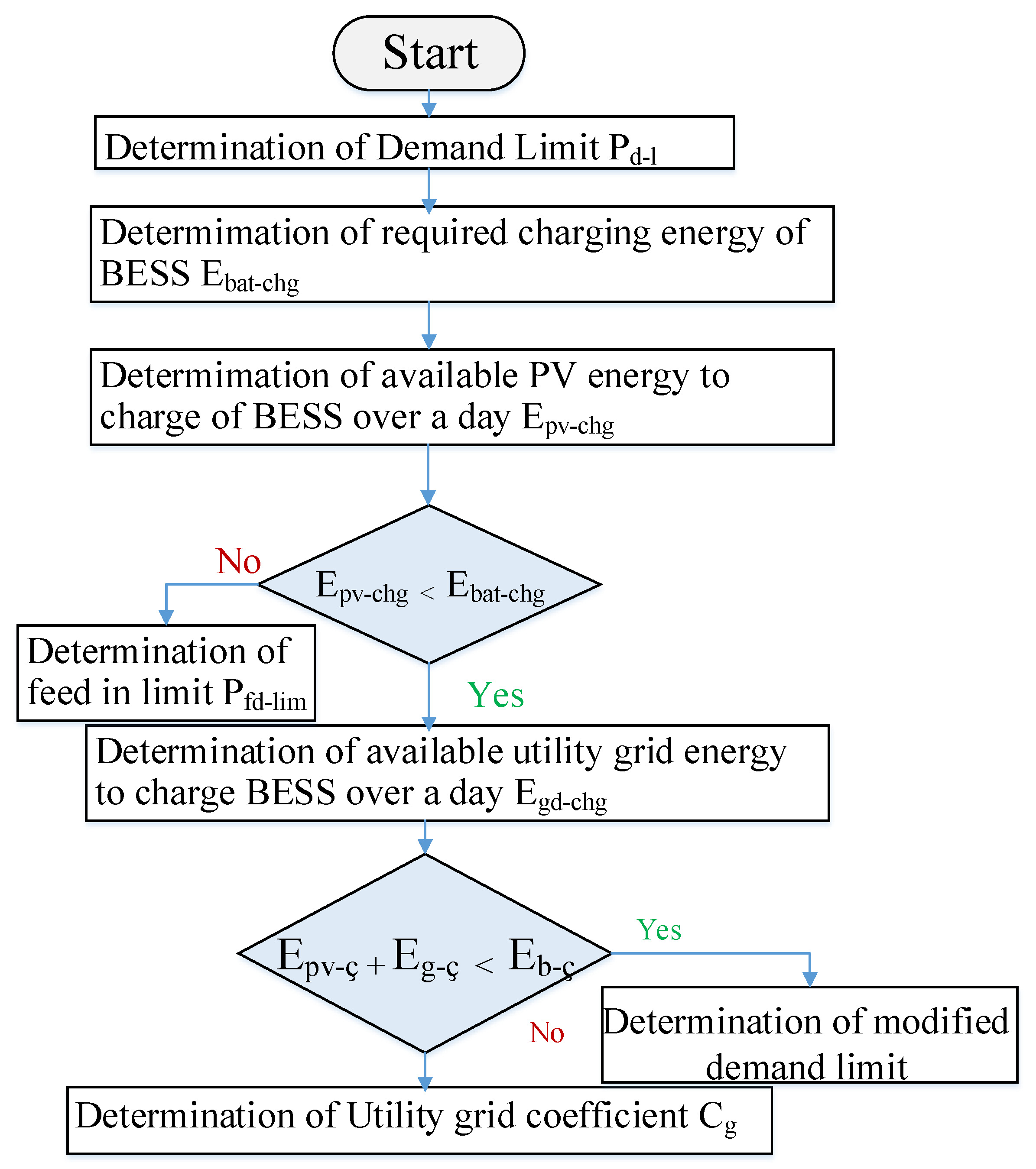
The suggested rule-based peak shaving management utilizes the predicted load demand, and PV and EV powers to determine the necessary inputs. These inputs include P d l , E b c , E pv c , E EV c , E gd c , C gd , P d l m , and P fd lm . Firstly, P d l , E b c , E EV c and E pv c are calculated. Next, E gd c is calculated if E pv c E b c , and P d l m is calculated only if E pv chg + E gd c E b c ; otherwise, C gd is calculated. If E pv c E b c , then P fd lm is calculated. The coordination of these inputs is given in the flowchart shown in Figure 4. Based on these inputs, the charging/discharging schedules of BES for peak shaving management are determined. The following technique is used to determine the required inputs for the suggested rule-based peak shaving management.

4.3.1. Demand Limit

A control variable, denoted as E b dch * , is defined to represent the BES dischargeable energy over 24 h. Its value can range from 0 kWh to the BES rated energy capacity, E b rated , which includes 0 kWh as well, i.e.,
0 E b dch E b rated
Given the BES rated energy capacity of 132 kWh, the dischargeable energy over 24 h, E b dch , is selected from the range of 0 kWh to 12 kWh. The demand limit is defined based on the value of E b dch , which is set to be equal to E b dch . The outcomes obtained from this approach are
E b dch = E b dch
P b dch ( t ) E b dch = 0 t ϵ t dch
When P LD ( t ) > P d l , the PV source or a battery delivers the required quantity of power P LD ( t ) P d l to the load. The load is powered by either a battery or a PV source, while any additional power needed to meet the demand is supplied by the BES, resulting as
P b dch ( t ) = ( P LD ( t ) P d l ) P pv ( t ) t ϵ t dch = 0 , o t h e r w i s e
Substituting (13) into (12) gives
( ( P LD ( t ) P d l ) P pv ( t ) ) E b dch = 0 t ϵ t dch
Equation (14) is in form of f ( P dem lm ) = 0 where
f ( P d l ) = ( ( P LD ( t ) P d l ) + P pv ( t ) ) E b dch t ϵ t dch
In Equation (15), P d l is an independent variable that needs to be solved using the root-finding method of the regula falsi approach [37]. This method combines the secant method and the bisection search theorem to converge for finding the equation root. Compared to the bisection method, the regula falsi method guarantees root convergence and provides faster response. For applying the method, ( P d l 1 , P d l 2 ) are selected such that f ( P d l 1 ) is positive and f ( P d l 2 ) is negative. Then, P d l 0 is calculated using the following equation:
P d l = 1 m ( 0 f ( P d l ) ) + P d l
where, m is defined as f P d l 2 f ( P d l 1 ) P dem lm 2 P dem l m 1 . Using Equation (16), we determine f ( P d l 0 ) . When | f ( P d l 0 ) | < e , P d l 0 becomes P d l . When | f ( P d l 0 ) | > e , either replace P d l 1 by P d l 0 , i f ( f ( P d l 0 ) > 0 ) or replace P d l 2 by P d l 0   i f ( f ( P d l 0 ) < 0 ) . Then, we continue the above process until P d l 0 equals P d l . The tolerance and slope of the regula falsi method are denoted e and m.

4.3.2. Daily Energy Demand for Charging BES

In order to allow for daily management flexibility, the amount of energy required to charge and discharge the BES over a 24 h period must be equal. This ensures that the system is balanced and can operate effectively, i.e.,
E b c = E b dch = E b dch

4.3.3. Daily PV Energy Availability for Charging BES

From Equation (17), the total energy E b c used to charge the BES can be determined from either the PV source or the utility grid. The first step is to determine the amount of PV energy available for charging the battery over a 24 h period, without the need to inject it into the grid. In the case when this available PV energy is not enough, we calculate the amount of utility grid energy available for charging the BES.
The P pv c is P pv ( t ) and P pv ( t ) P LD ( t ) P d l ( t ) during t c 1 and t c 2 , respectively, i.e.,
P pv c = P pv t t t c 1 = P pv ( t ) ( P LD ( t ) P dem lm ) t t c 2 = 0 , o t h e r w i s e .
To determine the PV energy that can be used to charge the BES over a 24 h period, the total PV energy output P pv chg over 24 h is summed up over 24 h. This is expressed as
E pv c = t = 1 T P pv c ( t )
In this context, T represents the predictive horizon for 24 h, which corresponds to a total of 144 TSs in our specific case.

4.3.4. Daily Utility Grid Energy Availability for Charging BES

If the condition E pv c E b c given in Equations (17) and (19) is satisfied, it implies that the available PV energy is not enough to fulfill the charging demand of the battery. As a result, if the demand limit is not exceeded, a shortage of energy is obtained from the utility grid. This indicates that the utility grid not utilized for battery charging during t c 2 . To restrict P gd to P d l during t c 2 , the power available from the utility grid for charging the battery is determined, which is P gd c ( t ) equals P d l P LD ( t ) , i.e.,
P gd c ( t ) = P d l P LD ( t ) t t c 1 = 0 o t h e r w i s e .
The total energy that can be obtained from the utility grid for charging the BES over a period of 24 h is calculated as the sum of P gd chg ( t ) over the day as illustrated in the following equation:
E gd c = t = 1 T P gd c ( t )

4.3.5. Utility Grid Energy Coefficient for Charging the BES

If the available PV energy is insufficient for fully charging the BES ( E pv c E b c & & E gd c + E pv c > E b c ) and the sum of the available utility grid energy and PV energy is greater than E b c , then the utility grid must provide the deficit energy amount required to fully charge the BES ( E b c E pv c ) as per Equations (17), (19) and (21). However, if the total available PV energy is used for charging the battery, only a portion of the utility grid energy is required. In such a situation, C gd E gd c can be used as the required utility grid energy to charge the BES, which equals E b c E pv c as shown in the following equations:
C g E gd c = E bat c E pv c
C g = ( E b c E pv c ) E gd c )

4.3.6. Modified Demand Limit

If the total available energy for charging the battery from both the PV source and the utility grid is less than the required energy to limit P gd to P d l as indicated by the condition E b c + E pv c E b c in Equations (17), (19) and (21), then the battery cannot be charged with the necessary amount of energy to maintain flexibility for daily control, resulting in a violation of S o C f matching with S o C i . To avoid this violation, P d l is adjusted so that the total energy available from both sources over the predictive horizon matches the expected energy discharge from the battery over the same duration. Thus, the modified demand limit can be calculated using the following expression:
P d l m = t = 1 T P LD ( t ) P pv ( t ) T

4.3.7. Feed-In Limit

If we consider Equations (17) and (19), when E pv c > E b c , the BES can be charged with the required energy amount without utilizing all available PV energy. Thus, a limit on PV power, P fd lm , is set to prevent the PV source from being used for charging the BES when P pv c ( t ) P fd lm . For the duration of t c , if P pv c ( t ) > P fd lm , then the battery will be charged fully with the energy P pv c ( t ) P fd lm , and the excess power will be sent to the grid, i.e.,
f ( P fd l ) = ( P ( pv c ( t ) P fd l ) E b c t t c t 1

4.4. The Rules Proposed for Peak Shaving Strategy

The charging/discharging schedules for the BES for the next day are determined based on the previously calculated inputs using peak shaving management rules. These rules are designed to maintain flexibility in daily management while limiting the feed-in powers and peak utility grid demand to the feed-in limits and appropriate demand, respectively. This section outlines the principles for the charging and discharging modes.
A. DCM (Through t dch )
Rule 1: The energy discharged by the BES is determined by ( P LD ( t ) P d l ) P pv ( t ) P EV ( t ) as per Equation (13).
B. CM1 (During t c 1 )
Rule 2: If E pv c E b c & & E pv c + E gd c > E b c , the amount of energy used to charge the BES from both the PV source and the utility grid can be expressed as P pv t + C gd P d l P LD t as per Equations (18), (20) and (23). The EV, if available at home, charges with the remaining grid power by the amount ( 1 C gd ) P d l P LD t .
Rule 3: If E pv chg E b c & & E pv c + E gd c E b c , the amount of energy used for battery charging from both sources (PV source and the utility grid) is expressed as P pv ( t ) + P d l m P LD ( t ) .
Rule 4: If E pv c > E b c & & P pv ( t ) > P fd lm , the charging amount of BES using the PV source is expressed as P pv ( t ) P fd lm as per Equation (18). The EV, if connected, charges with an amount equal to P fd lm .
Rule 5: If E pv c > E b c & & P pv ( t ) P fd lm , the PV source is not used for charging the BES and EV.
C. CM2 (During t c 2 )
Rule 6: If E pv c E b c , the amount of energy charged to the BES from the PV source can be expressed as P pv ( t ) ( P LD ( t ) P d l ) as per Equation (18).
Rule 7: If E pv c > E b c & & ( P pv ( t ) ( P LD ( t ) P d l ) ) > P fd lm , the charging amount of BES using the PV source is expressed as P pv ( t ) ( P LD ( t ) P d l ) ) P fd lm as per Equation (18). The EV, if connected, charges with an amount equal to P fd lm .
Rule 8: If E pv c > E b c & & P pv ( t ) ( P LD ( t ) P d l ) P fd lm , the PV source is not used for charging the BES and EV.
D. CM3 (During t c 3 )
Rule 9: If the current TS is less than 10 and a significant increase in load occurs before the availability of PV power, i.e., P LD ( t ) > P dem lm , the BES is charged from the utility grid with the amount of C gd P d l P LD t . This ensures that enough energy is stored in the BES to tackle the peak demand before the regular sunlight timings when the PV power is expected to be available. EV takes the charge from the grid with an amount ( 1 C gd ) P d l P LD t if P LD ( t ) < P d l during these time slots.
Rule 10: When the time of day is greater than 130 and the S o C ( t ) S o C f , the BES will charge from the utility grid with a quantity of C g P d l P LD t to ensure that the S o C f = S o C i for daily flexible management. EV takes the charge from the grid with an amount ( 1 C gd ) P d l P LD t if P LD ( t ) < P d l during these time slots.
The coulomb-counting approach described in [38] is utilized to determine the SoC of BES in the charging and discharging modes in this study. The resulting utility grid power, based on Rules 1–10, is presented in Table 3a.

4.5. Optimal Inputs Estimation

Optimizing the use of the BES to achieve utility grid electricity peak shaving is a crucial objective. To address this goal, the constraints and fitness function outlined below are taken into account to formulate an optimization problem:
m i n i m i z e f = E gd pk
subjected to,
P gd ( t ) + P pv ( t ) + P bat ( t ) + P EV ( t ) = P LD ( t )
S o C b , l S o C b ( t ) S o C b , u , S o C f = S o C i
P b c ( t ) P b c mx , P b dch ( t ) P b dch mx
E b dch E b rated
S o C E V , l S o C E V ( t ) S o C E V , u
P EV c ( t ) P EV c mx , P EV dch ( t ) P EV dch mx
The objective is to minimize the amount of energy drawn from the utility grid during peak demand E g d p k while maintaining a power balance as stated in Equation (27), ensuring flexibility in daily operations by enforcing constraints on the BES and EV SoC in Equations (28) and (31), imposing limitations on the charge/discharge power of the battery and EV as given in Equations (29) and (32), and setting a cap on the BES dischargeable energy for a day according to Equation (30). The considered system parameters for the proposed scheme are presented in Table 4. It is important to note that E gd pk in Equation (26) refers to the maximum energy drawn from the utility grid over the entire day, i.e.,
E gd pk = m a x i m u m ( E gd ( t ) ) t ϵ [ 0 , T ]
where E gd is determined as
E gd ( t ) = ( P g d ( t ) ) × T c
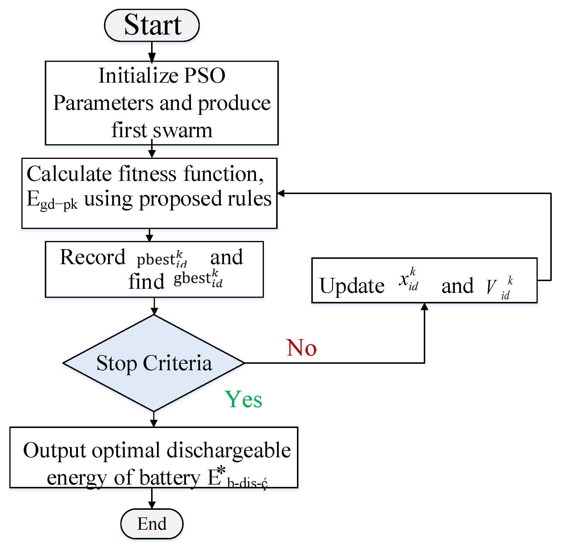
As mentioned earlier, the inputs required for peak shaving control rely on the control variable E * b dch . The problem at hand involves offline optimization with a fitness function that is nonlinear, and it is resolved through the utilization of PSO. PSO is a well-known heuristic optimization technique that is commonly employed to obtain solutions to the resource scheduling and peak shaving algorithms due to its ability to quickly reach the near-optimal solutions in a reasonable time frame [12]. As a result, PSO is well suited for this community-based architecture consisting of a large number of homes. The optimal dischargeable energy at the battery E * b dch is determined using PSO as represented in the flow diagram in Figure 5 [39]. After determining the value of E ob dch * , the inputs associated with E ob dch * are considered the optimal inputs needed for the proposed rule-based control, namely, P od l , E ob c , E opv c , E ogd c , C ogd , P od l , and P d l . Thus, the inputs that yield the optimal performance for the rule-based control are obtained by solving the optimization problem, which are then used by the suggested method for peak shaving management based on rules to generate optimal BES plans.

5. Simulation Results

The performance of the proposed method for grid-connected PV systems utilizing BES and EV is evaluated using MATLAB simulations with different load and PV power patterns to showcase its effectiveness. Table 3b presents the determined and listed optimal inputs for the control algorithm in each case. After conducting multiple runs of the PSO algorithm, the summer load profile with higher PV availability yielded the best fitness value. The optimal peak energy drawn from the utility grid in this case was determined to be 19.33 kWh, representing the minimum value achieved. Table 5 and Table 6 contain the quantitative and qualitative comparison between the proposed work and the existing work. In this section, the discussion focuses on the results obtained from the proposed technique for the two cases.

5.1. Case 1: Summer Load Profile with High PV Energy Availability

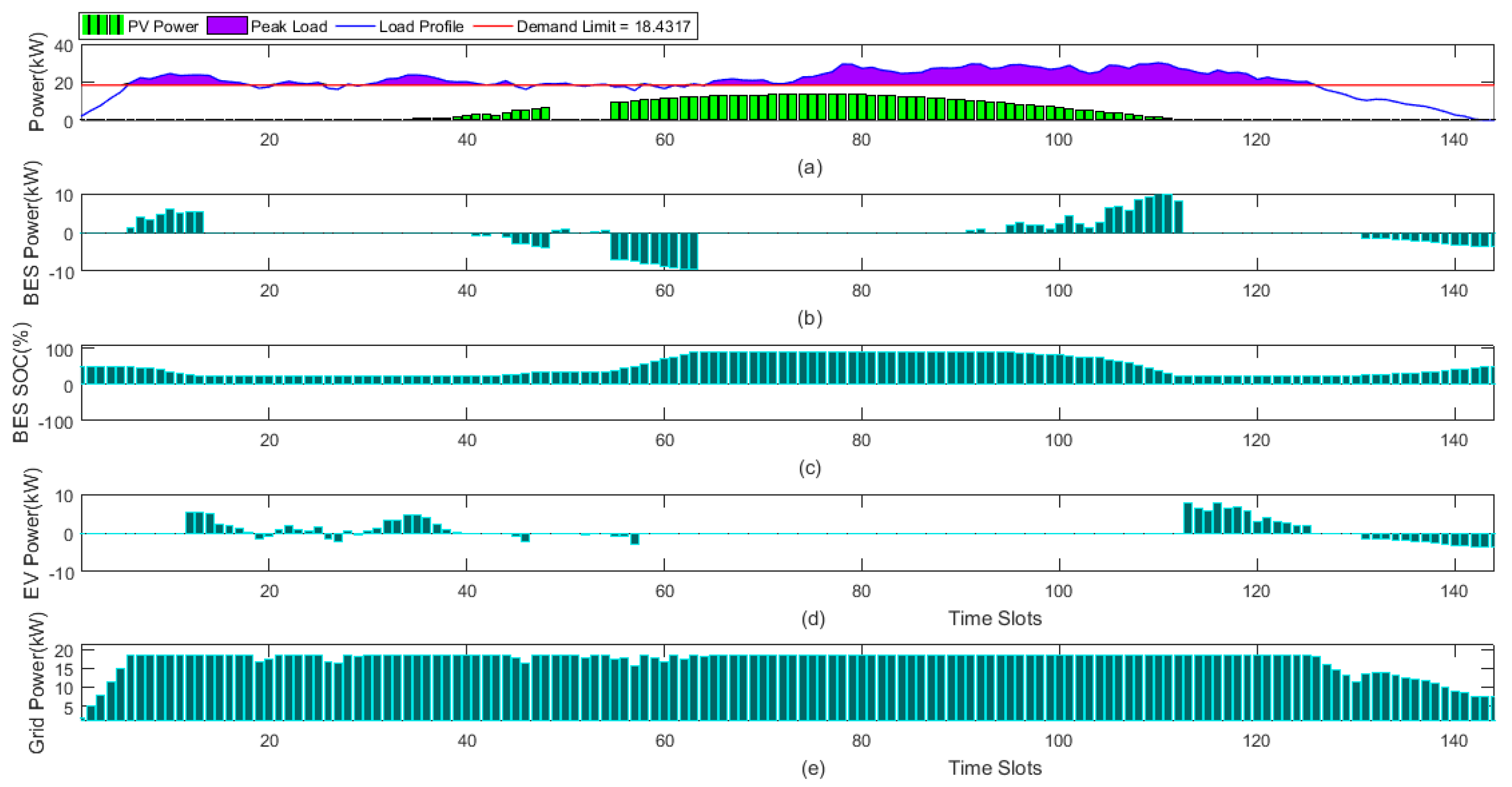
Figure 6a illustrates the load demand profile for summer, emphasizing the augmented availability of PV energy during daylight hours. The estimations based on P d l , E ob c , E opv c , E ogd c , C ogd and P ofd lm for summer are 18.4317 kW, 122.4544 kWh, 95.7421 kWh, 28.0261 kWh, 0.3 and 2.6009, respectively. The energy available from the PV system for charging the BES is more than the energy required for charging the BES: E opv c > E ob c . Consequently, the value of P od lm * is not applicable (NA), as presented in Table 3b. However, the utility grid power is utilized only at the end of the day to restore the SoC of BES to 50% for daily management.
Referring to Figure 6b, the discharge in minimum demand (DCH-MD) mode of BES occurs during the time periods of 6–13 and 91–112 TS until the BES state of charge (SOC) reaches 50%, based on the estimated value of P odem lm . Since EV is available during these time slots before the expected departure around t = 60 T S , EV takes up the load during t = 12–18, 21–25, 28, and 30–39 T S . During the time slots of 42, 45–46, 51–52 and 55–57 T S , EV charges itself for attaining a sufficient charge before the departure time for work. The BES takes the charge when PV is sufficient to take up the load at t = 40 60 T S . The EV is incorporated with a capacity of 140 kWh as two EVs are considered. The EV supports the peaks occurring before the departure time of 10:00 h while leaving significant charge for traveling to and coming back from the office. It again participates around 7:00 h for the peak occurring in evening. The different modes’ optimal charge/discharge schedules for the battery are illustrated in the Figure 6b. The resulting BES schedules are presented in the form of SoC in the depicted Figure 6c. Figure 6d shows the EV charge/discharge schedules in the available and connected TS. For the proposed scheme, the utility grid demand is illustrated in Figure 6e, indicating a cap at P od l = 18.4317 kW and a limit of 2.6009 kW for feed-in power. The figure also shows that the proposed scheme achieves 5.6% more percentage peak shaving (PPS) reduction as compared to the reference scheme [14]. Further comparison of the parameter values can be found in Table 3b.

5.2. Case 2: Winter Load Profile with Low PV Energy Availability

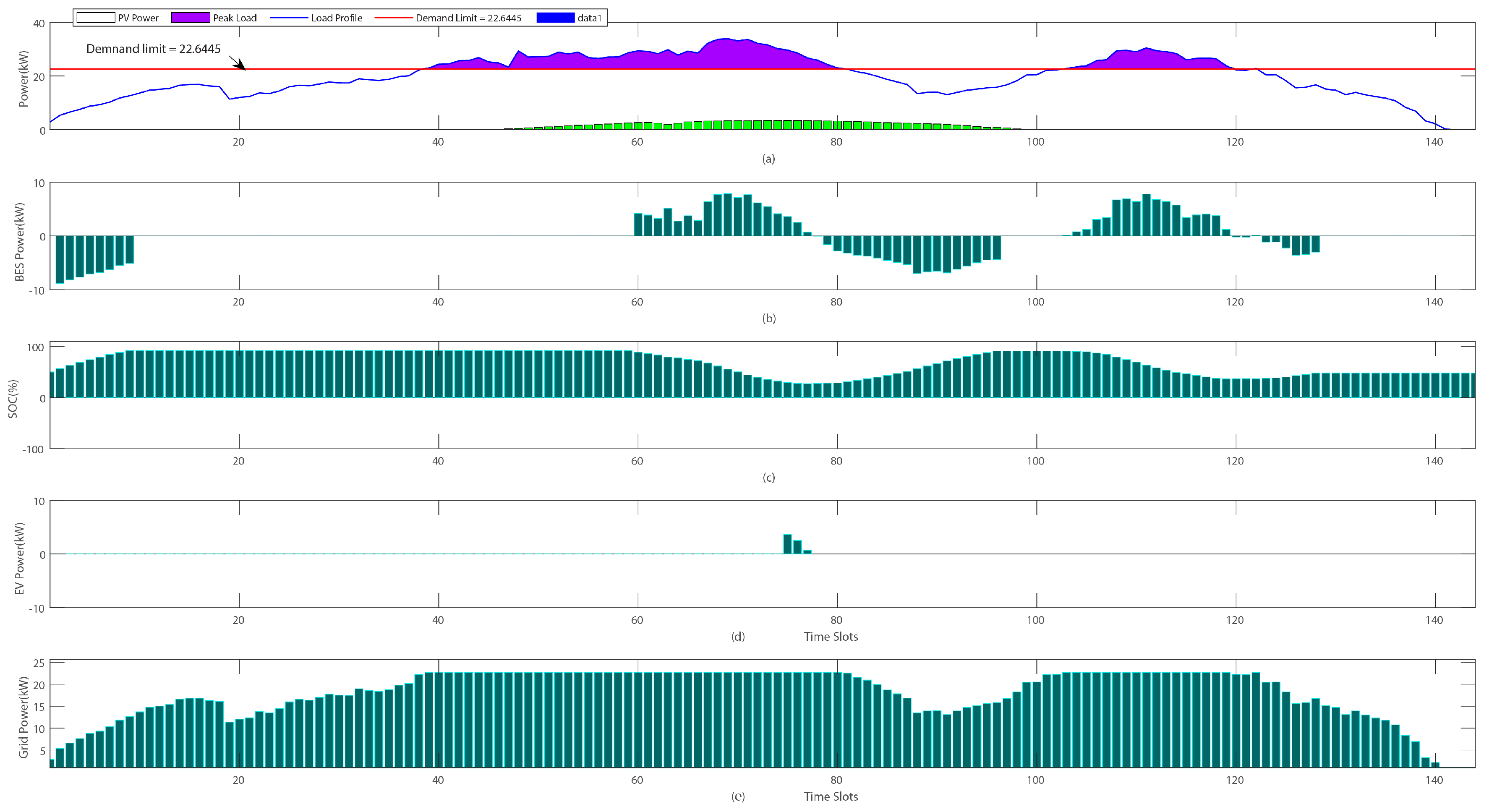
In this scenario, the load demand profile for winter, with lower PV energy availability throughout the day, is considered as shown in Figure 7. The values corresponding to P d l , E ob c , E opv c , E ogd c ,   and   C ogd are 22.6445 kW, 111.324 kWh, 43.8495 kWh, 118.6550 kWh and 0.1502, respectively, for winters. The PV energy available to charge the BES is not sufficient to meet the required energy for charging the battery. However, the combined energy available from PV and the utility grid is more than enough to charge the battery, E pv c E b c & & E gd c + E pv c > E b c . Therefore, in this case, the values of P od l * and P ofd lm are not applicable and are marked as NA as shown in Table 3b. Figure 7 shows the estimated P ob c , DCH-MD, which is the discharging mode that occurs during the period t = 60 - - 68 , 105 - - 119 T S . CH-M1 occurs during t = 1 - - 8 , 79 - - 106 T S . The optimal charge/discharge schedules for the BES in the mentioned modes are illustrated in Figure 7b. The SoC for the resulting BES schedules is depicted in Figure 7c. Figure 7d shows the EV charge/discharge schedules in the available and connected TS. Figure 7e reflects the utility grid demand. This indicates that the utility grid demand is constrained to P d lm = 22.5445 kW/TS with no feed-in power available. It is noticeable that the proposed scheme exhibits a 7.59% improvement in PPS reduction as compared to the reference scheme without EV. The EV supports the peaks occurring before the departure time of 11:00 h while leaving significant charge for traveling to and coming back from the office. Table 3b provides a detailed comparison of all the parameter values.

5.3. Case 3: Summer Load Profile with a Cloud Gust

Figure 8a illustrates the load demand profile for summer, emphasizing the augmented availability of PV energy during daylight hours with a gust of cloud that appears suddenly. The estimations based on P d l , E ob c , E opv c , E ogd c , C ogd and P ofd lm for summers are 18.4317 kW, 124.6860 kWh, 90.8623 kWh, 28.0261 kWh, 0.3 and 2.6009, respectively. The simulations are carried out for a special case, where an unexpected event occurs in the form of a gust of cloud. The PV which was available during the day time, suddenly disappears. It can be seen in Figure 8a that during the available hours of PV, it appears to be zero for about an hour during the TSs of 49 to 54. As can be seen in Figure 8a, the PV is shown to be zero in these TSs. The results in Figure 8 can be compared with those in Figure 6 for differences. The BES power as shown in Figure 8b starts discharging for taking up the load due to the unavailability of PV instead of charging as shown in Figure 6b for the available PV case during some of the TSs in the duration of TSs 49 to 54. The BES SoC in Figure 8c also attains a reduced value as compared to the case where the cloud gust is not available. It should be noted down here that the BES SoC does not drop down below its threshold. Hence, BES can alone take up the load in the absence of PV while preserving the EV charge so that it is sufficiently charged before the EV departure since our proposed strategy transfers the energy in the priority of PV first, ESS second and EV last.

6. Conclusions

In conclusion, this paper makes several key contributions in the field of community home energy management systems (HEMSs):
  • The concept of an optimal demand response is proposed within the context of a community home energy management system based on microgrids. The focus is on incorporating battery storage systems and electric vehicles to enhance the effectiveness of the demand response strategy.
  • A novel approach is presented, introducing a dynamic clustered load scheduling strategy tailored for grid-connected photovoltaic (PV) systems, incorporating battery energy storage systems and electric vehicles to effectively manage peak shaving. Furthermore, a rule-based method is employed to optimize the management process.
  • By integrating dynamic demand response and optimal peak shaving strategies, the system addresses reduces peak utilization grid power (PUGP) that increases grid stability by reducing reliance on the public grid.
  • The experimental results showcase constrained utility grid demand and feed-in powers across various load demand scenarios and PV power profiles.
  • The application of particle swarm optimization (PSO) improves the percentage of peak removal by an average of 7%, indicating the effectiveness of the proposed management strategy.
  • Future research can focus on enhancing the shared apartment architecture by conducting precise and accurate calculations of electric vehicle (EV), battery energy storage (BES), and photovoltaic (PV) ratings.
  • Further investigations can explore the implementation of metaheuristic optimization techniques, such as crow search (CSA) and hybrid grey wolf algorithm (HGWO), considering different types and scenarios of EVs, including vehicle-to-grid (V2G), grid to vehicle (G2V), vehicle-to-everything (V2X) and vehicle-to-vehicle (V2V) operations.
  • Exploring these areas in future research will present promising opportunities to improve the overall performance of HEMS and drive advancements in the field of energy management systems within community microgrids.

Author Contributions

Conceptualization, A.A. and H.A.K.; methodology, A.A. and M.A.A.; software and validation, A.A.; formal analysis and investigation, A.A., H.A.K. and K.S.; resources, A.A. and S.A.; writing—original draft preparation, A.A. and H.A.K.; writing—review and editing, A.A., K.S. and H.A.K.; visualization, A.A. and H.A.K.; supervision, M.A.A. and H.A.K.; project administration and funding acquisition, K.S. All authors have read and agreed to the published version of the manuscript.

Funding

This research work was funded by Institutional Fund Projects under grant no. IFPIP: 1219-717-1443. The authors gratefully acknowledge technical and financial support provided by the Ministry of Education and King Abdulaziz University, DSR, Jeddah, Saudi Arabia.

Conflicts of Interest

The authors declare no conflict of interest.

Nomenclature

DHEMSDynamic clustered home energy management system.
MGMicrogrid.
PARPeak-to-average ratio.
HEMSHome energy management system.
PUPPower usage pattern.
IBRInclined block rate.
PVPhotovoltaic.
PSOParticle swarm optimization.
AMIAdvanced metering infrastructure.
RTPReal time electricity pricing.
CAControllable appliance.
ATSActivation time slot.
ASTStarting time for operation of appliance
ATLTime length of appliance operation.
AETEnding time for operation of appliance.
LCSLower class.
MCSMiddle class.
BESBattery Energy Storage.
SoCState of charge.
PUGPPeak utility grid power.
PPSPercentage peak shaving.
UMCSUpper middle class.
HCSHigher class.
ECElectricity cost.
α a k ATS for appliance a of house k .
β a k AET for appliance a of house k .
t a k ATS for ath appliance of kth house
l a k ATL for appliance a of house k .
x a k Device rating for ath appliance of kth house
A k Set of CAs of kth house.
P a k Power consumption profile for appliance a of house k .
p a k τ Power consumption value for ath device of kth house, during τ th time slot.
τ Time slot.
P Power consumption scheduling matrix of size 80 × 144.
P scd Power consumption scheduling vector.
P c c PUP for cluster of community.
λ Penalty factor.
γ c A threshold based on count of houses under current community.
p c Power consumption of community being optimized.
rtp pc τ Real time electricity price of p c .
t h PUP set threshold at 2 kWh.
C h Current community houses set.
C c CAs current cluster.
μ PUP Mean PUP.
P gd , E gd Utility grid power (kW) and energy (kWh).
P EV , P b , P PV , P LD EV, battery, PV and load demand powers (kW).
P fd lm , P d l Feed-in and demand limits of the day (kW).
E b c Energy required for charging battery (kWh).
E b c mx Battery maximum charging power (kW).
E pv c , E gd c Available utility grid and PV energy for battery charging (kWh).
E b dch Dischargeable energy of the battery (kWh).
E b dch mx Maximum battery discharge power (kW).
E bat rated Rated energy capacity of battery (kWh).
C gd Coefficient of utility grid energy to charge the battery.
E b dch , E b c Discharging and charging power of battery (kW).
S o C a , S o C f Starting and ending SoC of the day.
S o C u , S o C l Upper and lower limits of SoC.

References

  1. Chen, B.; Wang, J.; Lu, X.; Chen, C.; Zhao, S. Networked Microgrids for Grid Resilience, Robustness, and Efficiency: A Review. IEEE Trans. Smart Grid 2021, 12, 18–32. [Google Scholar] [CrossRef]
  2. Ahmed, M.; Meegahapola, L.; Vahidnia, A.; Datta, M. Stability and Control Aspects of Microgrid Architectures—A Comprehensive Review. IEEE Access 2020, 8, 144730–144766. [Google Scholar] [CrossRef]
  3. Moazeni, F.; Khazaei, J.; Asrari, A. Step Towards Energy-Water Smart Microgrids; Buildings Thermal Energy and Water Demand Management Embedded in Economic Dispatch. IEEE Trans. Smart Grid 2021, 12, 3680–3691. [Google Scholar] [CrossRef]
  4. Leitão, J.; Gil, P.; Ribeiro, B.; Cardoso, A. A Survey on Home Energy Management. IEEE Access 2020, 8, 5699–5722. [Google Scholar] [CrossRef]
  5. Espina, E.; Llanos, J.; Burgos-Mellado, C.; Cárdenas-Dobson, R.; Martínez-Gómez, M.; Sáez, D. Distributed Control Strategies for Microgrids: An Overview. IEEE Access 2020, 8, 193412–193448. [Google Scholar] [CrossRef]
  6. Ali, S.; Rehman, A.U.; Wadud, Z.; Khan, I.; Murawwat, S.; Hafeez, G.; Albogamy, F.R.; khan, S.; Samuel, O. Demand Response Program for Efficient Demand-Side Management in Smart Grid Considering Renewable Energy Sources. IEEE Access 2022, 10, 53832–53853. [Google Scholar] [CrossRef]
  7. Abbasi, A.; Sultan, K.; Aziz, M.A.; Khan, A.U.; Khalid, H.A.; Guerrero, J.M.; Zafar, B.A. A Novel Dynamic Appliance Clustering Scheme in a Community Home Energy Management System for Improved Stability and Resiliency of Microgrids. IEEE Access 2021, 9, 142276–142288. [Google Scholar] [CrossRef]
  8. Zhang, Z.; Wang, Z.; Wang, H.; Zhang, H.; Yang, W.; Cao, R. Research on Bi-Level Optimized Operation Strategy of Microgrid Cluster Based on IABC Algorithm. IEEE Access 2021, 9, 15520–15529. [Google Scholar] [CrossRef]
  9. Dong, X.; Li, X.; Cheng, S. Energy Management Optimization of Microgrid Cluster Based on Multi-Agent-System and Hierarchical Stackelberg Game Theory. IEEE Access 2020, 8, 206183–206197. [Google Scholar] [CrossRef]
  10. Waseem, M.; Lin, Z.; Liu, S.; Sajjad, I.A.; Aziz, T. Optimal GWCSO-based home appliances scheduling for demand response considering end-users comfort. Electr. Power Syst. Res. 2020, 187, 106477. [Google Scholar] [CrossRef]
  11. Aziz, M.A.; Qureshi, I.M.; Cheema, T.A.; Rashid, E.A. Community based home energy management system. IIUM Eng. J. 2017, 18, 43–55. [Google Scholar] [CrossRef]
  12. Aziz, M.A.; Qureshi, I.M.; Cheema, T.A.; Malik, A.N. Time based device clustering for domestic power scheduling. Int. J. Adv. Appl. Sci. 2016, 1, 1–9. [Google Scholar] [CrossRef]
  13. Leadbetter, J.; Swan, L. Battery storage system for residential electricity peak demand shaving. Energy Build. 2012, 55, 685–692. [Google Scholar] [CrossRef]
  14. Abbasi, A.; Khalid, H.A.; Habib, R.; Khan Adnan, U. A Novel Dynamic Load Scheduling and Peak Shaving Control Scheme in Community Home Energy Management System Based Microgrids. IEEE Access 2023, 11, 32508–32522. [Google Scholar] [CrossRef]
  15. Lei, T.; Min, Z.; Gao, Q.; Song, L.; Zhang, X.; Zhang, X. The Architecture Optimization and Energy Management Technology of Aircraft Power Systems: A Review and Future Trends. Energies 2022, 15, 4109. [Google Scholar] [CrossRef]
  16. Reddy, K.R.; Meikandasivam, S. Load Flattening and Voltage Regulation Using Plug-In Electric Vehicle’s Storage Capacity with Vehicle Prioritization Using ANFIS. IEEE Trans. Sustain. Energy 2020, 11, 260–270. [Google Scholar] [CrossRef]
  17. Hafiz, F.; Awal, M.A.; Queiroz, A.R.d.; Husain, I. Real-Time Stochastic Optimization of Energy Storage Management Using Deep Learning-Based Forecasts for Residential PV Applications. IEEE Trans. Ind. Appl. 2020, 56, 2216–2226. [Google Scholar] [CrossRef]
  18. Lengyel, L. Validating rule-based algorithms. J. Appl. Sci. 2015, 12, 59–75. [Google Scholar]
  19. Kumar Jha, U.; Soren, N.; Sharma, A. An Efficient HEMS for Demand Response Considering TOU Pricing Scheme and Incentives. In Proceedings of the 2018 2nd International Conference on Power, Energy and Environment: Towards Smart Technology (ICEPE), Shillong, India, 1–2 June 2018; pp. 1–6. [Google Scholar] [CrossRef]
  20. Bruno, S.; Giannoccaro, G.; La Scala, M. A Demand Response Implementation in Tertiary Buildings Through Model Predictive Control. IEEE Trans. Ind. Appl. 2019, 55, 7052–7061. [Google Scholar] [CrossRef]
  21. Celik, B.; Roche, R.; Suryanarayanan, S.; Bouquain, D.; Miraoui, A. Electric energy management in residential areas through coordination of multiple smart homes. Renew. Sustain. Energy Rev. 2017, 80, 260–275. [Google Scholar] [CrossRef] [Green Version]
  22. Mahmud, K.; Hossain, M.J.; Town, G.E. Peak-Load Reduction by Coordinated Response of Photovoltaics, Battery Storage, and Electric Vehicles. IEEE Access 2018, 6, 29353–29365. [Google Scholar] [CrossRef]
  23. Greenwood, D.M.; Wade, N.S.; Taylor, P.C.; Papadopoulos, P.; Heyward, N. A Probabilistic Method Combining Electrical Energy Storage and Real-Time Thermal Ratings to Defer Network Reinforcement. IEEE Trans. Sustain. Energy 2017, 8, 374–384. [Google Scholar] [CrossRef] [Green Version]
  24. Riffonneau, Y.; Bacha, S.; Barruel, F.; Ploix, S. Optimal Power Flow Management for Grid Connected PV Systems with Batteries. IEEE Trans. Sustain. Energy 2011, 2, 309–320. [Google Scholar] [CrossRef]
  25. Angenendt, G.; Zurmühlen, S.; Mir-Montazeri, R.; Magnor, D.; Sauer, D.U. Enhancing battery lifetime in PV battery home storage system using forecast based operating strategies. Energy Procedia 2016, 99, 80–88. [Google Scholar] [CrossRef] [Green Version]
  26. Vedullapalli, D.T.; Hadidi, R.; Schroeder, B. Combined HVAC and Battery Scheduling for Demand Response in a Building. IEEE Trans. Ind. Appl. 2019, 55, 7008–7014. [Google Scholar] [CrossRef]
  27. Manojkumar, R.; Kumar, C.; Ganguly, S.; Catalão, J.P.S. Optimal Peak Shaving Control Using Dynamic Demand and Feed-In Limits for Grid-Connected PV Sources With Batteries. IEEE Syst. J. 2021, 15, 5560–5570. [Google Scholar] [CrossRef]
  28. Erdinc, O.; Paterakis, N.G.; Mendes, T.D.P.; Bakirtzis, A.G.; Catalão, J.P.S. Smart Household Operation Considering Bi-Directional EV and ESS Utilization by Real-Time Pricing-Based DR. IEEE Trans. Smart Grid 2015, 6, 1281–1291. [Google Scholar] [CrossRef]
  29. Sadeghian, O.; Oshnoei, A.; Mohammadi-ivatloo, B.; Vahidinasab, V.; Anvari-Moghaddam, A. A comprehensive review on electric vehicles smart charging: Solutions, strategies, technologies, and challenges. J. Energy Storage 2022, 54, 105241. [Google Scholar] [CrossRef]
  30. Dik, A.; Kutlu, C.; Omer, S.; Boukhanouf, R.; Su, Y.; Riffat, S. An Approach for Energy Management of Renewable Energy Sources Using Electric Vehicles and Heat Pumps in an Integrated Electricity Grid System. Energy Build. 2023, 294, 113261. [Google Scholar] [CrossRef]
  31. Ravi, S.S.; Aziz, M. Utilization of Electric Vehicles for Vehicle-to-Grid Services: Progress and Perspectives. Energies 2022, 15, 589. [Google Scholar] [CrossRef]
  32. Mojumder, M.R.H.; Ahmed Antara, F.; Hasanuzzaman, M.; Alamri, B.; Alsharef, M. Electric Vehicle-to-Grid (V2G) Technologies: Impact on the Power Grid and Battery. Sustainability 2022, 14, 13856. [Google Scholar] [CrossRef]
  33. Hussain, B.; Hasan, Q.U.; Javaid, N.; Guizani, M.; Almogren, A.; Alamri, A. An Innovative Heuristic Algorithm for IoT-Enabled Smart Homes for Developing Countries. IEEE Access 2018, 6, 15550–15575. [Google Scholar] [CrossRef]
  34. Schettini, T.; dell’Amico, M.; Fumero, F.; Jabali, O.; Malucelli, F. Locating and Sizing Electric Vehicle Chargers Considering Multiple Technologies. Energies 2023, 16, 4186. [Google Scholar] [CrossRef]
  35. Pakistan Bureau of Statistics. Available online: http://www.pbs.gov.pk/content/housinh-units-number-rooms-and-type (accessed on 1 June 2020).
  36. Amber, K.P.; Ahmad, R.; Farmanbar, M.; Bashir, M.A.; Mehmood, S. Unlocking household electricity consumption in Pakistan. Buildings 2021, 11, 566. [Google Scholar] [CrossRef]
  37. Chun, S.; Kwasinski, A. Analysis of Classical Root-Finding Methods Applied to Digital Maximum Power Point Tracking for Sustainable Photovoltaic Energy Generation. IEEE Trans. Power Electron. 2011, 26, 3730–3743. [Google Scholar] [CrossRef]
  38. Hosseinzadeh, M.; Salmasi, F.R. Robust Optimal Power Management System for a Hybrid AC/DC Micro-Grid. IEEE Trans. Sustain. Energy 2015, 6, 675–687. [Google Scholar] [CrossRef]
  39. Menos, A.C.; Lamprinos, I.; Georgilakis, P.S. Particle Swarm Optimization in Residential Demand-Side Management: A Review on Scheduling and Control Algorithmsfor Demand Response Provision. Energies 2022, 15, 2211. [Google Scholar] [CrossRef]
Figure 1. Community-based HEMS framework.
Energies 16 05024 g001
Figure 2. DHEMS parameters for clustering.
Energies 16 05024 g002
Figure 3. BES operating modes at different time slots [14].
Energies 16 05024 g003
Figure 4. Input’s coordination needed for rule-based management control method.
Energies 16 05024 g004
Figure 5. Flowchart outlining the proposed dynamic home energy management system (DHEMS) method.
Energies 16 05024 g005
Figure 6. Case–1 (summer) subplots (a) profiles for load demand and PV power supply, (b) battery’s charge/discharge schedules, (c) battery’s SoC, (d) EV power, (e) grid power utility.
Energies 16 05024 g006
Figure 7. Case–2 (winters) subplots (a) profiles for load demand and PV power supply, (b) battery’s charge/discharge schedules, (c) battery’s SoC, (d) EV power, (e) grid power utility.
Energies 16 05024 g007
Figure 8. Case–3 (summer cloud) subplots (a) profiles for load demand and PV power supply, (b) battery’s charge/discharge schedules, (c) battery’s SoC, (d) EV power, (e) grid power utility.
Energies 16 05024 g008
Table 1. Summer/winter CAs usage parameters [7].
Controllable AppliancesSummers Operating HoursWinters Operating Hours
LCS Air Conditioner1 to 4, 21 to 244 to 6
Electric Heating ApplianceNA5 to 8, 19 to 21
Washing Machine1 to 8, 15 to 201 to 11
Clothes DryerNA7 to 12
Dishwashing Machine1 to 13, 18 to 249 to 15, 16 to 24
Water pump1 to 8, 13 to 15, 20 to 241 to 7, 17 to 24
Electric Tea Kettle4 to 6, 10 to 12, 17 to 195 to 9, 11 to 1, 18 to 20
Food Steamer1 to 6, 9 to 11, 16 to 181 to 8, 10 to 12, 15 to 18
MCS Air Conditioner1 to 6, 20 to 245 to 7
Electric Heating ApplianceNA6 to 8, 15 to 22
Washing Machine1 to 9, 17 to 211 to 12
Clothes Dryer7 to 15, 20 to 248 to 15
Dish-washing machine9 to 12, 15 to 18, 19 to 249 to 15, 16 to 1
Water pump9 to 10, 21 to 238 to 11, 20 to 22
Electric Tea Kettle6 to 10, 13 to 15, 18 to 206 to 10, 18 to 21
Food Steamer1 to 10, 12 to 14, 16 to 191 to 12, 16 to 19
UMC Air Conditioner1 to 8, 19 to 245 to 9
Electric Heating Appliance15 to 207 to 9, 15 to 23
Washing Machine1 to 10, 17 to 221 to 13
Clothes Dryer11 to 18, 11 to 129 to 17
Dish-washing machine9 to 12, 12 to 17, 19 to 249 to 15, 19 to 23
Water pump1 to 11, 20 to 241 to 12, 20 to 24
Electric Tea Kettle8 to 13, 13 to 16, 19 to 218 to 13, 18 to 22
Food Steamer1 to 11, 12 to 15, 18 to 231 to 13, 17 to 22
HCS Air Conditioner1 to 241 to 24
Electric Heating Appliance15 to 2415 to 24
Washing Machine1 to 241 to 15
Clothes Dryer1 to 249 to 21
Dish-washing Machine10 to 3, 7 to 2410 to 2, 5 to 24
Water pump1 to 241 to 24
Electric Tea Kettle11 to 14, 18 to 2410 to 13, 18 to 24
Food Steamer1 to 12, 18 to 241 to 14, 18 to 23
Electric Vehicle1 to 7, 14 to 15, 19 to 241 to 11, 18 to 24
Table 2. CAs power rating (kW) across four distinct classes.
Lower-ClassMiddle-ClassUpper-Middle-ClassHigher-Class
Electric Vehicle---70
Air Conditioner11.522.5
Washing Machine0.50.51.51.5
Electric Heating Appliance1.41.41.41.4
Dish-washing Machine0.40.41.51.5
Clothes dryer1.81.855
Electric Tea Kettle1.51.51.51.5
Water Pump0.50.51.51.5
Food Steamer0.60.60.60.6
Table 3. Operating modes of a utility grid power in (a) and optimal inputs of the proposed control algorithm for two cases in (b).
(a)
ModesRuleUtility Grid Power
DCM1 P d l
CM12 P LD ( t ) + C gd P d l P LD ( t )
CM13 P d l m
CM14 P LD ( t ) P fd lm
CM15 P LD ( t ) P pv ( t )
CM26 P d l
CM27 P d l P fd lm
CM28 P LD ( t ) P pv ( t )
CM39&10 C gd P d l P LD ( t )
(b)
Input ParameterCase 1Case 2Case 3
kw/kWhOPSRef.OPSRef.OPS
P od l 18.4319.9322.6423.518.43
E ob c 122.45156.37111.3127.42124.68
E opv c 95.7487.8143.8448.5690.86
E og c 28.020.4118.6586.9728.02
C ogd 0.360.570.150.160.3
P od l m NANANANANA
P ofd lm 2.602.24NANA2.60
Table 4. System parameters [27].
ParameterValueParameterValue
P dem pk 36 kW S o C i / S o c u 0.2/0.9
P pv inst 15 kW S o C i 0.5
E bat rated 132 kW P bat chg m 10 kW
A h bat rated 600 Ah P bat dsch m 10 kW
E EV rated 170 kW P EV chg / dsch m 10 kW
Table 5. Quantitative comparison between the proposed technique and the existing work.
ParametersPUGP (kW)PPS (%)
SchemesCase 1Case 2Case 1Case 2
Reference [14]19.132123.544543.5530.53
Proposed DHEMS18.431722.614549.1538.12
Table 6. Qualitative comparison between the proposed technique and the existing work.
ParameterReference LiteratureProposed
[13,22,23][24][25][26][27]
HEMS based StageNC 1 NCNC NCDynamic
Demand LimitFixedFixedNCDynamicDynamicDynamic
Feed in limitNCNCDynamicNCDynamicDynamic
Electric VehicleNCNCNCNCNCConsidered
Daily managementNCFlexibleNCNCFlexibleFlexible
1 NC = Not Considered.
Disclaimer/Publisher’s Note: The statements, opinions and data contained in all publications are solely those of the individual author(s) and contributor(s) and not of MDPI and/or the editor(s). MDPI and/or the editor(s) disclaim responsibility for any injury to people or property resulting from any ideas, methods, instructions or products referred to in the content.