Article

Passivity-Based Control and Current Balance Control of a Current-Source Pulse-Width-Modulation Rectifier

1
Guizhou Electric Power Research Institute of Guizhou Power Grid Co., Ltd., Guiyang 550002, China
2
Joint Laboratory of Ice Prevention and Disaster Reduction of China Southern Power Grid Co., Ltd., Guiyang 550002, China
3
Department of Electrical Engineering and Applied Electronic Technology, Tsinghua University, Beijing 100084, China
4
Kaili Power Supply Bureau of Guizhou Power Grid Co., Ltd., Kaili 556099, China
*
Author to whom correspondence should be addressed.
Energies 2023, 16(12), 4682; https://doi.org/10.3390/en16124682
Submission received: 4 May 2023 / Revised: 4 June 2023 / Accepted: 8 June 2023 / Published: 13 June 2023

Abstract

:
To improve the static performance, dynamic performance, and current balance of a current-source PWM rectifier with multi-modules, a comprehensive control method with passivity-based control and current balance control is proposed in this paper. Current balance control, which is based on AC voltage sequencing, has the advantages of being easy to implement and not being limited by the number of modules. Mathematical modelling, controller design, and simulation verification were conducted successively, and the results show that the comprehensive control method has a low current impact and high power quality. At the same time, module currents are well balanced, even under external disturbance, when using current balance control.

1. Introduction

With the development of power electronics and modern control technology, rectifier technology has developed from uncontrolled diode rectifiers, to half-controlled thyristor rectifiers, to fully controlled pulse-width-modulation (PWM) rectifiers [1]. Compared with the uncontrolled rectifier and half-controlled rectifier, the PWM rectifier has the advantages of having a higher power factor, lower harmonic pollution [2], a smaller size, and a lighter weight of its passive components [3].
According to their form of energy storage, PWM rectifiers can be divided into voltage-source PWM rectifiers and current-source PWM rectifiers. Compared with the voltage-source PWM rectifier, the current-source PWM rectifier evolved from a buck circuit, has the advantages of continuous current regulation and short-circuit current suppression, and is suitable for high-power step-down rectifier applications such as DC ice-melting on high-voltage transmission lines [4], as well as being used as an induction heating power supply [5], wind power grid connection [6], motor drive [7], and other applications.
Compared to a traditional GTO, an integrated gate-commutated thyristor (IGCT) has significant advantages, such as lower loss, higher switching speed, higher reliability, and easier application. These advantages make IGCTs more suitable for application, e.g., in high-power rectifiers, reactive compensation, DC circuit breakers, and high-voltage converters [8,9,10].
The control goal of a current-source PWM rectifier is maintaining a constant DC current and controllable AC power factor. One control method is direct current control, which comprises state feedback control [11], model predictive control [12], and nonlinear control [13], and has the advantage of a fast response speed. Other control methods are indirect current control (ICC) [14], input current displacement factor compensation-based ICC [15], and delay angle-based ICC [16]; all of these indirectly control the AC current through modulated waves.
References [17,18] adopted the abc static coordinate system state-variable feedback compensation method to achieve unit power factor control. Reference [19] adopted a simple and easily implemented control method to achieve unit power factor control. Reference [11] proposed a nonlinear state-variable feedback control method based on the dq axis, which can achieve independent control of active and reactive power. The above methods all achieve unit power factor control, which can achieve decoupling control of active and reactive power.
Model predictive control [20] is also used in the voltage-source PWM rectifier, but it relies heavily on a mathematical model, and it requires a large amount of computation to achieve optimization. Passivity-based control [21] was proposed by R. Ortega and M. Spong in 1989; it has the advantages of a simple design and easy implementation, and has been used in various converters.
To eliminate low-order harmonic currents, a LC low-pass filter is often used in the current-source PWM rectifier. When using IGCTs as fully controlled power electronic switches, a switching frequency of approximately 500–800 Hz is usually selected, and the cut-off frequency is often approximately 300–400 Hz. Because this is close to the voltage harmonic frequency, it is prone to harmonic amplification and may cause poor power quality, system instability, and even rectifier damage. This problem is more obvious in weak systems [22].
To improve the cut-off frequency of an LC filter, a method of parallel connection of multiple modules can be adopted. This method uses multi-level technology to eliminate low harmonic currents, improve the cut-off frequency, reduce the cost and volume of the filter, and suppress possible resonance.
In addition, the parallel connection of multiple modules, which multiplies the capacity of the rectifier, is suitable for various uses in various capacities. However, the modules have some current differences because of pulse differences and arm circuit parameter differences. The current difference causes some modules to have higher currents, and it may cause overcurrent and overheating, and may even damage the module. Reference [23] adopted the method of adjusting the zero-vector freewheeling current to make the output levels of the zero-vector freewheeling current different. The inductance voltage difference was used to adjust the inductance current to achieve current balance. However, this method has a high switching frequency and is not suitable for applications with a small number of zero vectors and a short timeframe. Reference [24] adopted a quasi-specific harmonic elimination method, which added bypass pulses to achieve current balance on the basis of specific harmonic elimination. However, this method requires a large number of offline calculations, cannot achieve real-time calculations, and cannot be applied to any number of modules in parallel.
Based on the situation described above, to improve the static and dynamic performances and current balance of a current-source PWM rectifier with multi-modules, a comprehensive control method with passivity-based control and current balance control is proposed in this paper. The current balance control is based on AC voltage sequencing; it has the advantages of being easy to implement and not being limited by the number of modules, and the module currents are well balanced, even under external disturbance. Mathematical modelling, controller design, and simulation verification are successively conducted in the paper.

2. Current-Source PWM Rectifier with Multiple Modules

As shown in Figure 1, the current-source PWM rectifier is composed of N current-source PWM modules, where S1–S6 are fully controlled power electronic switches, such as IGBTs, IGCTs, and MOSFETs; D1–D6 are power electronic diodes; and Sk and Dk (k = 1–6) are series connected to form the main circuit of the current-source PWM rectifier. Ljp and Ljn (j = 1, 2, …, N) are positive and negative inductances which are used to limit the circulating current among modules. An LC low-pass filter is used to filter out lower harmonic currents; it can achieve an auxiliary commutation function simultaneously. Ldc and RL indicate DC load inductance and resistance, respectively.
When the switches are controlled by PWM modulation one by one in the sequence of S1–S6, the AC voltage changes to DC voltage. When multi-level control technology is used in multiple modules, the equivalent switching frequency can be multiplied.

3. Mathematical Model and Controller Design

3.1. EL Mathematical Model

According to Kirchhoff’s law, the AC side voltages and currents can be expressed as
{ L d i s j d t = v s j v c j R i s j   C d v c j d t = i s j i o j v c j R c , j = a , b , c
where vsj and vcj (j = a, b, c) are system voltages and filter capacitor voltages, respectively, isj and ioj (j = a, b, c) are system currents and rectifier currents, respectively, and R and Rc are loss equivalent resistances related to current and voltage, respectively.
Similarly, the DC voltage and current can be expressed as
{ ( L dc + L 1 p + L 1 n ) d i dc d t = v dc i dc R L   v dc = j = a , b , c v c j S j
where vdc and idc are the DC voltage and current and Sj is the switching function of the phase j.
Here, the synchronous rotation coordinate is adopted, and the AC voltages and currents are transformed into dq voltages and currents:
( i sd i sq ) = C abc / dq ( i sa i sb i sc ) , ( i od i oq ) = C abc / dq ( i oa i ob i oc ) , ( v sd v sq ) = C abc / dq ( v sa v sb v sc ) , ( v cd v cq ) = C abc / dq ( v ca v cb v cc )
where isd and isq are dq coordinate system currents, iod and ioq are dq coordinate rectifier currents, vsd and vsq are dq coordinate system voltages, and vcd and vcq are dq coordinate filter capacitor voltages. Cabc/dq is the transform matrix from the abc coordinate to the dq coordinate. To maintain the same magnitude as the abc coordinate, the transform matrix is defined as:
C abc / dq = 2 3 ( cos ( ω t ) cos ( ω t 2 π / 3 ) cos ( ω t + 2 π / 3 ) sin ( ω t ) sin ( ω t 2 π / 3 ) sin ( ω t + 2 π / 3 ) )
After the above coordinate transformation, Equation (2) can be further represented as
( v sd v sq ) = ( L d d t ω L ω L L d d t ) ( i sd i sq ) + ( R 0 0 R ) ( i sd i sq ) + ( v cd v cq )
( i sd i sq ) = ( C d d t ω C ω C C d d t ) ( v cd v cq ) + ( 1 R c 0 0 1 R c ) ( v cd v cq ) + ( i od i oq )
Thus, we can obtain the mathematical model of the current-source PWM rectifier in Euler–Lagrange (EL) form:
M k X k + J k X k + R k X k = V k , k = 1 , 2
where M1 and M2 are positive definite symmetric coefficient matrices, J1 and J2 are skew-symmetric coefficient matrices, R1 and R2 are positive coefficient matrices, X1 and X2 are state-variable vectors, and V1 and V2 are control input variable vectors.
M 1 = ( L 0 0 L ) , J 1 = ( 0 ω L ω L 0 ) , R 1 = ( R 0 0 R ) , X 1 = ( i sd i sq ) , V 1 = ( v sd v cd v sq v cq ) ,
M 2 = ( C 0 0 C ) , J 2 = ( 0 ω C ω C 0 ) , R 2 = ( 1 R c 0 0 1 R c ) , X 2 = ( v cd v cq ) , V 2 = ( i sd i od i sq i oq ) ,

3.2. Passive Analysis

It is assumed that the system storage energy function is
H k = 1 2 X k T M k X k , k = 1 , 2
By performing differentiation, we can obtain
H k = X k T M k X k = X k T ( V k J k X k R k X k ) = X k T V k X k T R k X k
If the output variable vectors are defined as Yk = Xk, the energy supply rate Yk TVk is valid for any input variable Vk; that is to say, the system is strictly passive.

3.3. Passivity-Based Controller Design

The control goal is X1X1*=(isd* isq*)T and X2X2*=(vcd* vcq*)T, where isd* and isq* are the control objects of the system currents and vcd* and vcq* are the control objects of the filter capacitor voltages.
It is assumed that the error vector is Xke = XkXk*; the EL model in error vector mode can be expressed as
M k X k e + J k X k e + R k X k e = 0
Combining Equation (7) with Equation (12), we can obtain
M k X k e + R k X k e = V k ( M k X k * + J k X k + R k X k * )
To accelerate the convergence of Xk with Xk*, damping injection matrices Rd1 = diag{r11 r11} and Rd2 = diag{g11 g11} are used; this can be expressed as
M k X k e + ( R k + R d k ) X k e = V k ( M k X k * + J k X k + R k X k * R d k X k e )
Thus, the passivity-based control controller can be designed as
V k = M k X k * + J k X k + R k X k * R d k X k e
Further, it can be expressed as
{ v sd v cd * = L d i sd * d t + R i sd * ω L i sq r 11 ( i sd i sd * ) v sq v cq * = L d i sq * d t + R i sq * + ω L i sd r 11 ( i sq i sq * )
{ i sd i od * = C d v cd * d t + v cd * R c ω C v cq g 11 ( v cd v cd * ) i sq i oq * = C d v cq * d t + v cq * R c + ω C v cd g 11 ( v cq v cq * )
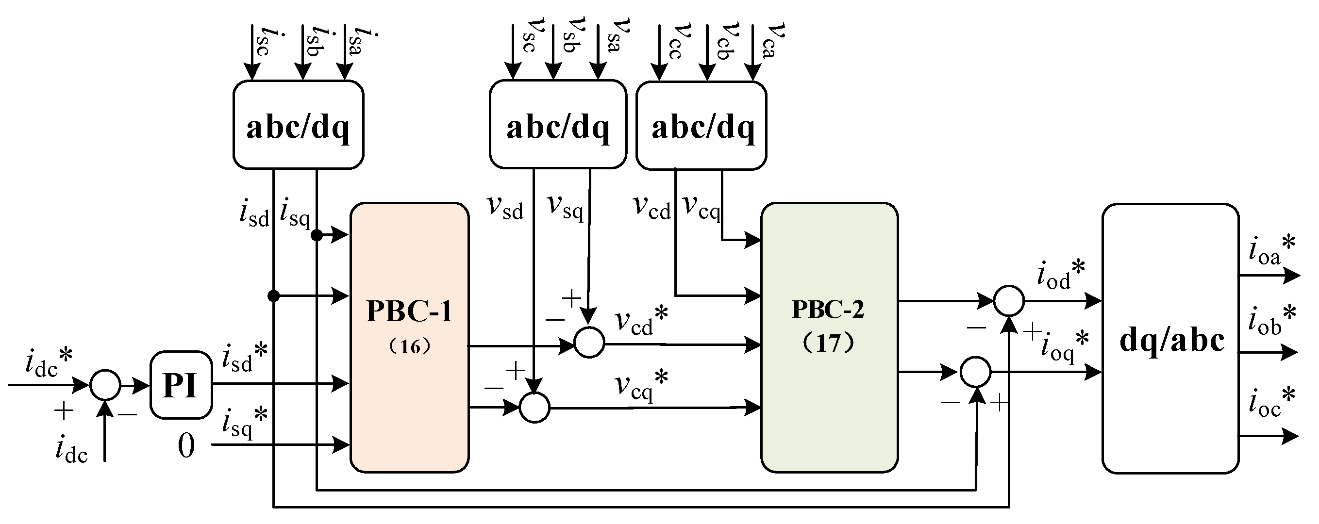
As shown in Figure 2, the current reference (isd*) can be obtained from a PI controller with DC current (idc) closed-loop control, the filter capacitor voltage references (vcd* and vcq*) can be obtained from PBC controller No. 1, and the rectifier current references (iod* and ioq*) can be obtained from PBC controller No. 2; then, the current references ioa*, iob*, and ioc* can be obtained by inversely transforming the dq to the abc coordinate.

4. Current Balance Control

As shown in Figure 3, the phase-switching function is a three-valued function of 1, 0, and −1, where 1 represents the upper switch being on and the lower switch being off, −1 represents the upper switch being off and the lower switch being on, and 0 represents the upper and lower switches both being on. In addition, the current-source PWM rectifier has nine current vectors, where I7, I8, and I9 are zero vectors representing the simultaneous conduction of the upper and lower switches of phase A, phase B, and phase C, respectively.
(1)
Generate module current references:
For N parallel modules, a carrier phase shift is performed to generate module current references, and the phase shift angle is
θ s = 2 π N k c
where kc = fc/f0 is the ratio of the carrier frequency to the fundamental frequency; the module current references are generated by the phase shifting of ioa*, iob*, and ioc*, and they satisfy ima* + imb* + imc* = 0. If adding together all of the module current references, the references will be multi-level waves.
(2)
Obtain the sector of the current reference vector:
According to the three-phase current references ima*, imb*, and imc*, the current vector Im*ejθm can be obtained, where Im* and θm are the amplitude and angle of the current vector, respectively. Then, we can obtain the sector of the current vector:
N s = mod ( floor ( θ + π / 6 π / 3 ) + 1 ,   6 )
where floor() is a rounding-down function and mod() is a remainder function.
(3)
Select the current subvector combination:
To minimize the switching frequency, an appropriate subvector and zero-vector combination should be selected. When the reference vector is in an odd sector, an upper switch is always on, and the lower switches transfer currents between the three lower arms. When the reference vector is in an even sector, a lower switch is always on, and the upper switches transfer currents between the three upper arms. Taking Sector I as an example, it consists of vectors of I6 (1, −1, 0), I1 (1, 0, −1), and I7 (0, 0, 0), the upper switch S1 is on all of the time, and the lower switches S6, S2, and S4 transfer currents, in turn, to phase B, C, and A. I7 represents the simultaneous conduction of S1 and S4.
(4)
Calculate the number of subvectors:
Further, taking Sector I as an example, it is assumed that the number of current vectors I6, I1, and I7 are n6, n1, and n7, respectively, and that they satisfy
{ ( i ma * , i mb * , i mc * ) = n 6 ( 1 , 1 , 0 ) + n 1 ( 1 , 0 , 1 ) + n 7 ( 0 , 0 , 0 ) n 6 + n 1 + n 7 = N
Further, it is organized as
( N i mb * i mc * ) = ( 1 1 1 1 0 0 0 1 0 ) ( n 6 n 1 n 7 )
and the number of current vectors can be calculated by solving the equation above.
(5)
Assign current subvectors to the odd sector:
First, the lower bridge arm currents i1n, i2n, …, and iNn are arranged in descending order from large to small. A small voltage difference is applied to the lower bridge arm with a larger current, which means that the lower bridge arm with a larger voltage is switched on.
Second, the n6-phase B voltages vcb, n1-phase C voltages vcc, and n7-phase A voltages vca are arranged in descending order from large to small.
Finally, the current subvectors are assigned one by one, according to the two orders, to achieve the lower bridge arm current balance. Similarly, when the current vector is in Sector III or VI, the same method can be used for lower bridge arm current sequencing, phase voltage sequencing, and current subvector assignment.
(6)
Assign current subvectors to the even sector:
However, when the current vector is in Sector II, the lower switch of phase C is on. At this time, the upper bridge arm currents i1p, i2p, …, and iNp are arranged in descending order from large to small. A small voltage difference is applied to the upper bridge arm with a larger current, which means that the upper bridge arm with a smaller voltage is switched on.
Then, it should take the n1-phase A voltages vca, n2-phase B voltages vcb, and 8-phase C voltages vcc and arrange them in ascending order from small to large. The current subvectors are assigned one by one, according to the two orders, to achieve the upper bridge arm current balance. When the current vector is in Sector IV or VII, the same method can be used for upper bridge arm current sequencing, phase voltage sequencing, and current subvector assignment. Figure 4 shows the current balance control diagram based on current and voltage sequencing.

5. Simulation Verification

Based on passivity-based control and current balance control, a SIMULINK simulation model was built and simulation research was conducted. Table 1 shows the main circuit and control parameters of the multi-module current-source PWM rectifier. The magnetic application reveals nonlinear characteristics, its power loss cannot be ignored in high-power applications, and it can be solved using more accurate models that are available in the literature [25,26,27].
An accurate derivation of the diode equivalent average voltage and switching cell parasitic resistance is given in [28]. According to the principle of energy conservation, the average equivalent resistances of the inductor, switch, and diode in buck–boost converters are given by [29]:
r j _ av = 4 3 ( D + D 1 ) r j , j = L , switch , diode
where rj is the inductor, switch, or diode resistance; DT is the conduction time of the switch; D1T is the freewheeling time of the diode; and T =1/fs, where fs is the switching frequency.
Compared with the buck–boost converter, the average equivalent parasitic resistances of current-source PWM rectifiers are complex, and an ideal inductor was used to provide a simplified simulation parameter model in this simulation.

5.1. PBC Control Simulation

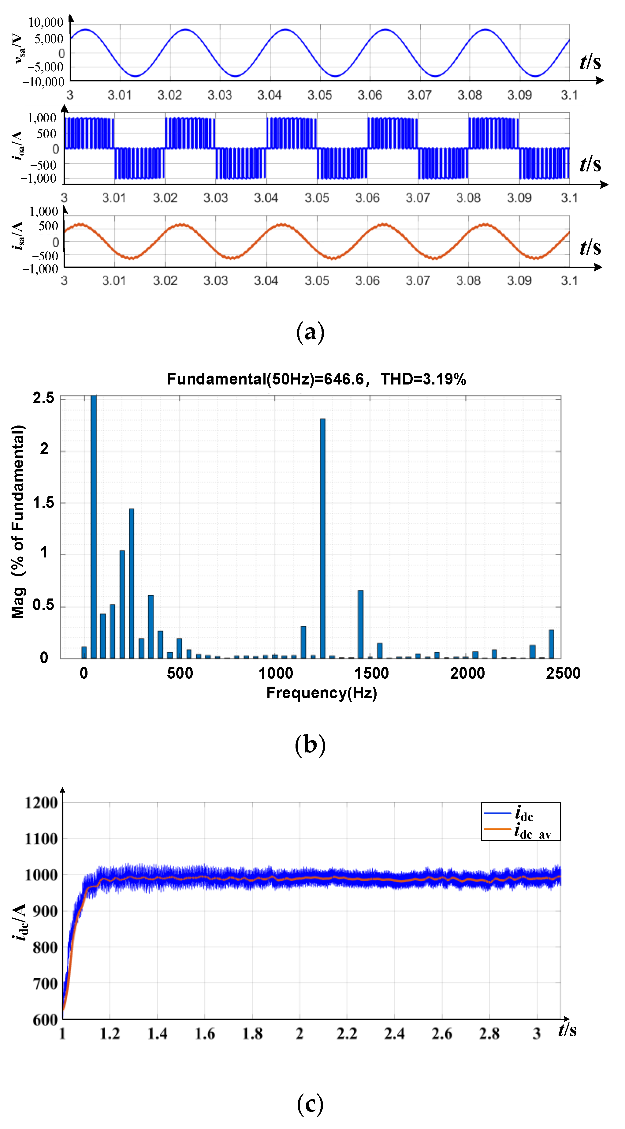
Figure 5 shows current simulation waveforms with a switching frequency of 750 Hz. As shown in Figure 5a, the AC current is a pulse waveform with a peak current value of 1000 A, and the filtered system current is a sinusoidal waveform with a peak value of 700 A. Figure 5b shows that the total harmonic distortion (THD) rate of the system current is 3.19%, which is lower than the design requirement of 5.00%. Figure 5c shows that the DC current can be continuously adjusted from 0 to the rated value (1000 A), and its current ripple is less than 3.2%.

5.2. Current Balance Control Simulation

Figure 6 shows the upper and lower bridge arm current simulation waveforms. Its total output current is 6000 A with six modules, and the upper and lower bridge arm currents are all balanced with the proposed current balance control. The maximum current difference is 40 A, which means the current unbalance rate is not greater than 4%.
When t1 = 0.2 s, the current balance control is disabled, the currents of Module 2 and 3 increase gradually, the currents of Module 5 and 6 decrease gradually, and the currents of Module 1 and 4 show nearly no change. When t2 = 0.3 s, the currents of Modules 2 and 3 are 2266 A, the currents of Modules 5 and 6 are 0 A, and the maximum current difference is 2266 A, which means that the current unbalance rate is 226.6%. The currents of different modules reveal a seriously unbalanced state.
When the current balance control is enabled again, the currents of Module 2 and 3 decrease rapidly, while the currents of Module 5 and 6 increase rapidly. When t3 = 0.323 s, the currents of different modules are balanced again, and the transient time for current balance control is 23 ms.
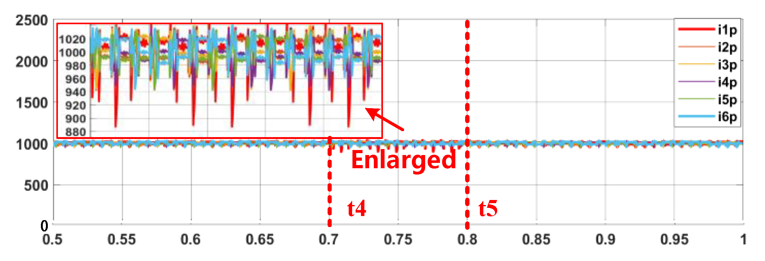
Figure 7 shows the upper bridge arm current simulation waveforms with a large circuit parameter difference. When t4 = 0.7 s, an extra inductor of 3 mH is connected in parallel to the positive inductor of Module 1, and the positive inductance of Module 1 decreases from 3 mH to 1.5 mH. At this time, the currents of different modules are still balanced; only the current ripple of Module 1 is larger compared with the other modules. This shows that the proposed current balance control has a good control effect, even if the main circuit parameters vary greatly.
The simulation results show that passivity-based control and the proposed current balance control, which is based on AC voltage sorting, have a good power quality and current balance control effect, and can still ensure good current balance with significant main circuit parameter differences.

6. Conclusions

This paper offers a comprehensive control method with passivity-based control and current balance control for current-source PWM rectifiers. The simulation results show that the system has a low current impact and high power quality, and it can balance the output currents of multiple modules, regardless of enormous inductance differences.
In addition to the control method, other topics need to be studied in the future, such as loss analysis and parasitic parameter influence analysis. In addition, a prototype experiment, to be conducted in future research, is very important for the validation of the proposed control technique.

Author Contributions

Data curation and funding acquisition, H.Z., Q.Y., K.X. and X.M.; project administration, B.Z.; formal analysis and writing—review and editing, J.L. All authors have read and agreed to the published version of the manuscript.

Funding

The authors offer their sincere appreciation for the support of the Key Science and Technology Projects of Southern Power Grid (066600KK52210005).

Conflicts of Interest

The authors declare no conflict of interest.

References

  1. Shi, W.; Jiang, Q.; Hu, M.; Tang, G.Q.; Jiang, P. Mathematical model and main circuit design of three-phase voltage-source PWM rectifier. J. Southeast Univ. (Nat. Sci. Ed.) 2002, 32, 50–55. [Google Scholar]
  2. Xianping, Z.; Yaxi, L.; Lei, P. Analysis and design of LCL type filter for three-phase voltage source rectifier. Electrotech. Appl. 2007, 26, 65–68. [Google Scholar]
  3. Yao, W.Z.; Wang, Z.A. Research on three-phase large capacity PWM rectifier. J. Hunan Inst. Eng. 2001, 11, 1–4. [Google Scholar]
  4. Xu, K.; Ma, X.; Rao, C. Research and comparison of DC deicing technologies based on full bridge MMC and thyristor rectifier. South. Power Syst. Technol. 2020, 14, 45–53. [Google Scholar]
  5. Zhang, W.J. Current Source PWM Rectifier and Its Application in Induction Heating. Ph.D. Thesis, Zhejiang University, Hangzhou, China, 2007. [Google Scholar]
  6. Popat, M.; Wu, B.; Zargari, N.R. A novel decoupled interconnecting method for current-source converter-based offshore wind farms. IEEE Trans. Power Electron. 2012, 27, 4224–4233. [Google Scholar] [CrossRef]
  7. Zhu, N.; Xu, D.; Wu, B.; Zargari, N.R.; Kazerani, M.; Liu, F. Common-mode voltage reduction methods for current-source converters in medium-voltage drives. IEEE Trans. Power Electron. 2013, 28, 995–1006. [Google Scholar] [CrossRef]
  8. Burgos, R.P.; Wiechmann, E.P.; Holtz, J. Complex state-space modeling and nonlinear control of active front-end converters. IEEE Trans. Ind. Electron. 2005, 52, 363–377. [Google Scholar] [CrossRef]
  9. Liu, W.H.; Hu, Y.C.; Liu, B.; Wang, Z.H. IGCT and IEGT- new high power silicon switches suitable for STATCOM. Autom. Electr. Power Syst. 2000, 23, 66–70. [Google Scholar]
  10. Liu, W.H.; Song, Q.; Yan, G.G. Medium voltage drive with NPC three-level inverter using IGCTs. Autom. Electr. Power Syst. 2002, 26, 61–65. [Google Scholar]
  11. Espinoza, J.R.; Joos, G. State variable decoupling and power flow control in PWM current-source rectifiers. IEEE Trans. Ind. Electron. 1998, 45, 78–87. [Google Scholar] [CrossRef] [Green Version]
  12. Liu, Y.H.; Watson, N.R.; Zhou, K.L.; Yang, B.F. Converter system nonlinear modelling and control for transmission applications-Part II: CSC systems. IEEE Trans. Power Deliv. 2013, 28, 1391–1401. [Google Scholar] [CrossRef]
  13. Zhu, X.R. Research on Current Source PWM Rectifier and Its Nonlinear Control Strategy. Ph.D. Thesis, North China Electric Power University, Baoding, China, 2009. [Google Scholar]
  14. Wu, K.; Li, Y.; Lin, P.; Wu, K.Z.; Zhang, W.J. Current source PWM rectifier based on indirect current control. Proc. CSU-EPSA 2008, 20, 62–65. [Google Scholar]
  15. Hiti, S.; Vlatkovic, V.; Borojevic, D.; Lee, F. A new control algorithm for three-phase PWM buck rectifier with input displacement factor compensation. IEEE Trans. Power Electron. 1994, 9, 173–180. [Google Scholar] [CrossRef]
  16. Liu, H.P.; Qiu, B.B.; Peng, D.L.; Ren, F.; Guo, Q.; Zheng, Q. Improvement strategy for indirect current control of current source pulse width modulation rectifier. Power Syst. Technol. 2012, 36, 182–187. [Google Scholar]
  17. Sato, Y.; Kataoka, T. State feedback control of current type PWM AC-to-DC converters. IEEE Trans. Ind. Appl. 1993, 29, 1090–1097. [Google Scholar] [CrossRef]
  18. Wang, X.; Ooi, B. Real-time multi-DSP control of three-phase current-source unity power factor PWM rectifier. IEEE Trans. Power Electron. 1993, 8, 295–300. [Google Scholar] [CrossRef]
  19. Zargari, N.; Joos, G. An on-line operated near unity power factor PWM rectifier with minimum control requirements. In Proceedings of the 20th Annual Conference of IEEE Industrial Electronics, Bologna, Italy, 5–9 September 1994; pp. 593–598. [Google Scholar]
  20. Jin, T.; Guo, J.; Mohamed, M.A.; Wang, M. A novel model predictive control via optimized vector selection method for common-mode voltage reduction of three-phase inverters. IEEE Access 2019, 7, 95351–95363. [Google Scholar] [CrossRef]
  21. Jin, T.; Guo, J.; Mohamed, M.A.; Wang, M. An improved three-stages cascading passivity-based control of grid-connected LCL converter in unbalanced weak grid condition. IEEE Access 2021, 9, 89497–89506. [Google Scholar]
  22. Liserre, M.; Blaabjerg, F.; Hansen, S. Design and control of an LCL-filter-based three-phase active rectifier. IEEE Trans. Ind. Appl. 2005, 41, 1281–1291. [Google Scholar] [CrossRef]
  23. Bai, Z.; Ma, H.; Xu, D.; Wu, B. Control strategy with a generalized DC current balancing method for multimodule current-source converter. IEEE Trans. Power Electron. 2014, 29, 366–373. [Google Scholar] [CrossRef]
  24. Alakran, F.; Simoes, M.G. Multilevel current source converter-based STATCOM suitable for medium-voltage applications. IEEE Trans. Power Deliv. 2021, 36, 1222–1232. [Google Scholar] [CrossRef]
  25. Corti, F.; Reatti, A.; Lozito, G.M.; Cardelli, E.; Laudani, A. Influence of non-linearity in losses estimation of magnetic components for DC-DC converters. Energies 2021, 14, 6498. [Google Scholar] [CrossRef]
  26. Boteler, D.H. Characteristics of time-varying inductance. IEEE Trans. Magn. 1994, 30, 172–176. [Google Scholar] [CrossRef]
  27. Akbari, M.; Rezaei-Zare, A.; Cheema, M.A.M.; Kalicki, T. Air gap inductance calculation for transformer transient model. IEEE Trans. Power Deliv. 2021, 36, 492–494. [Google Scholar] [CrossRef]
  28. Corti, F.; Laudani, A.; Lozito, G.M.; Reatti, A. Computationally Efficient Modeling of DC-DC Converters for PV Applications. Energies 2020, 13, 5100. [Google Scholar] [CrossRef]
  29. Reatti, A.; Balzani, M. PWM switch model of a buck-boost converter operated under discontinuous conduction mode. In Proceedings of the 48th Midwest Symposium on Circuits and Systems, Cincinnati, OH, USA, 7–10 August 2005; pp. 667–670. [Google Scholar]
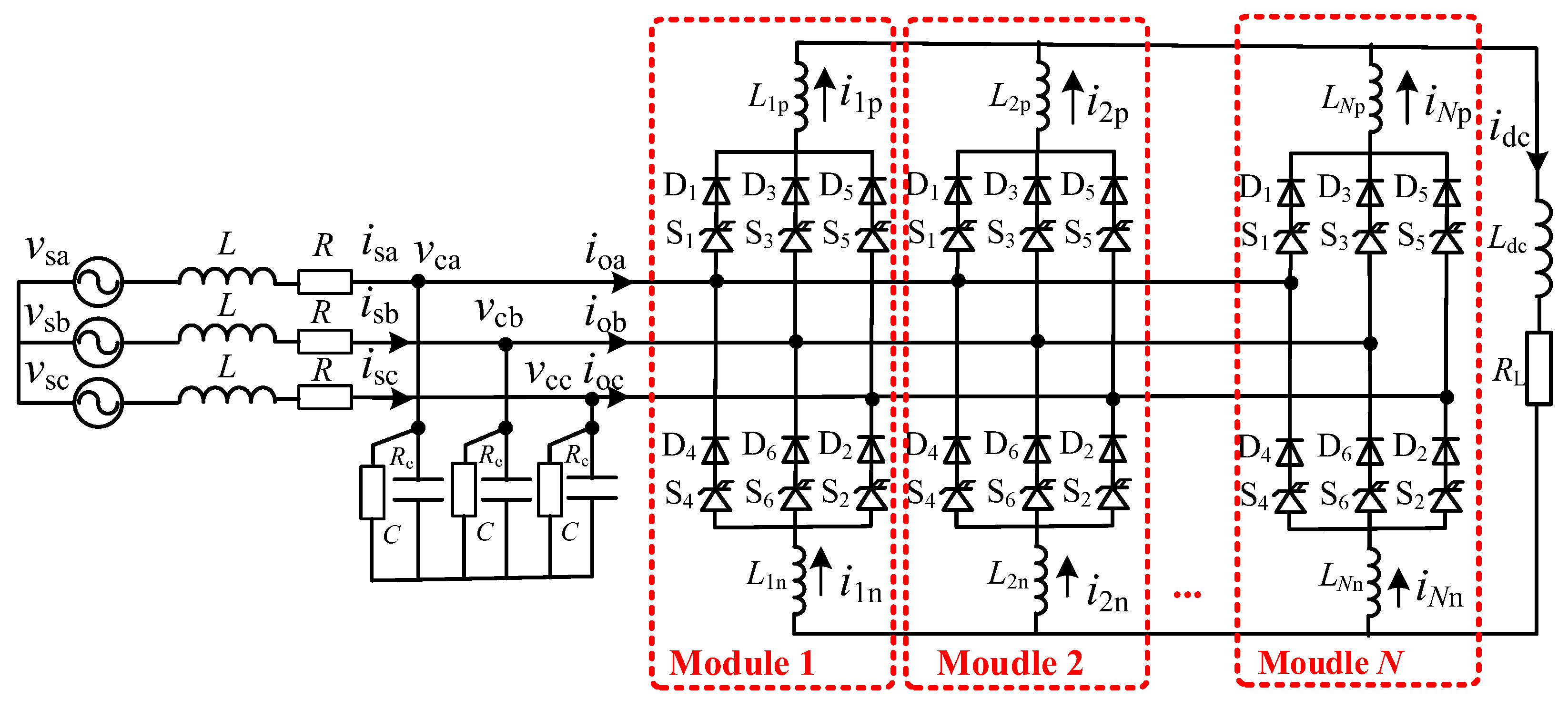
Figure 1. Current-source PWM rectifier with multi-modules.
Energies 16 04682 g001
Figure 2. Passivity-based control diagram.
Energies 16 04682 g002
Figure 3. Current vectors of current-source PWM rectifier.
Energies 16 04682 g003
Figure 4. Current balance control diagram based on current and voltage sequencing.
Energies 16 04682 g004
Figure 5. AC and DC current simulation waveforms. (a) Output current and system current waveforms. (b) System current and FFT analysis. (c) DC current and its average waveforms.
Energies 16 04682 g005
Figure 6. Normal current balance control simulation waveforms. (a) Upper bridge arm current waveforms. (b) Lower bridge arm current waveforms.
Energies 16 04682 g006
Figure 7. Current balance control waveforms with large circuit parameter difference.
Energies 16 04682 g007
Table 1. Main circuit and control parameters.
ParameterValue
AC voltage Vs/kV10
DC current Idc/A0–1000
filter inductance L/mH3
filter capacitance C/uF160
DC inductance Ldc/mH40
damping coefficient r113.00
damping coefficient g110.11
Number of parallel modules6
Positive and negative inductance Lp, Ln/mH3
Disclaimer/Publisher’s Note: The statements, opinions and data contained in all publications are solely those of the individual author(s) and contributor(s) and not of MDPI and/or the editor(s). MDPI and/or the editor(s) disclaim responsibility for any injury to people or property resulting from any ideas, methods, instructions or products referred to in the content.