Article

Development and Validation of a Variable Displacement Variable Compression Ratio Miller Cycle Technology on an Automotive Gasoline Engine

1
Research Center for Advanced Powertrain Technology, Hunan University, Changsha 410082, China
2
Hunan Dazi Power Technology Co., Ltd., Changsha 410221, China
3
Mechanical and Electrical Engineering, Central South University of Forestry and Technology, Changsha 410004, China
*
Author to whom correspondence should be addressed.
Energies 2023, 16(11), 4480; https://doi.org/10.3390/en16114480
Submission received: 14 March 2023 / Revised: 15 May 2023 / Accepted: 30 May 2023 / Published: 1 June 2023

Abstract

:
At partial load, traditional automotive gasoline engines have high pumping losses due to the throttling of the intake charge for load control. Variable Valve Timing (VVT) and the introduction of externally cooled EGR could reduce the pumping losses but only with a very limited effect. On the other hand, in the medium to full load range, the engine cannot utilize a high compression ratio due to limitations in knocking. A variable displacement, variable compression ratio device which utilizes an asymmetric camshaft to realize the different closure times of the two intake valves is discussed in this paper. The large-scale change in the intake valve timing leads to the large-scale change in the effective cylinder volume at the intake valve closure, which realizes a variable cylinder volume and a variable effective compression ratio. The device is utilized to reduce the pumping losses and to increase the in-cylinder thermal efficiency at the same time. Engine dyno test results indicate that, in the low to medium load range, a later closure of the intake valve could reduce the effective cylinder volume, and the intake pressure could be significantly increased, and therefore pumping losses reduced. However, the reduced effective cylinder volume due to a later intake valve closure would lead to reduction in the effective compression ratio (ECR) and a drop in in-cylinder thermal efficiency. Therefore, there is a balance point between the pumping loss reduction and the drop in in-cylinder thermal efficiency. On the other side, in the medium to full load range, when avoiding knocking becomes the major controlling factor of the combustion phasing (degree of constant-volume combustion) and the effective expansion ratio (EER), too high of an effective compression ratio would lead to significant drop in the effective expansion ratio EER and also the in-cylinder thermal efficiency. Therefore, there exists a best compromise between the ECR and EER, and the best system would be one with a moderate ECR but an EER as high as possible. The quantitative equations which include both ECR and EER in the thermal efficiency calculations captured the above observations pretty well and can be utilized to optimize for the best compromise of IVC, EVO, ECR, EER and engine performances during the concept stage and/or the calibration stage of an engine.

1. Introduction

Traditional automotive gasoline engines use stoichiometric homogeneous charge, when the engine works under a low to medium load range, a throttling of the intake charge to reduce the charge pressure and density is necessary to realize the required engine output. The throttling of the intake charge introduces significant pumping losses. Variable valve timing (VVT) to delay the intake valve closure timing and to reduce the effective cylinder volume can improve pumping losses [1]. The introduction of externally cooled exhaust gas recirculation (EGR) [2] could also reduce the pumping losses by the elevated intake port pressure. However, since the change in cylinder volume by a conversional VVT device is very limited, the improvement to the pumping losses is very marginal. Similarly, improvement to the pumping losses via EGR is also limited because the quantity of EGR that can be utilized before it impacts the combustion process is usually less than 20%. A variable valve lift (VVL) [3,4] device could change the effective cylinder volumes at a large scale; therefore, it can significantly reduce the pumping losses at a light load. However, the manufacturing cost and the difficulty in calibration, as well as the controlling of a VVL, would make it difficult to be widely applied. Hence, up to now, although there are many patents and concepts that were filed or published claiming to be able to reduce the pumping losses at light load, there are few devices that have been adopted and utilized in production engines.
On the other hand, the thermal to work conversion efficiency of the in-cylinder high pressure cycle of an engine is well known to be associated to the in-cylinder compression ratio [5,6]: the higher the in-cylinder compression ratio, the higher the in-cylinder thermal efficiency. This conclusion is completely true at low to medium loads when knocking is not a concern. However, at a medium to full load range, when the compression pressure and temperature are high enough to cause knocking, a higher compression ratio will produce an even higher compression pressure and temperature, which will elevate the knocking tendency and the ignition timing, as well as the whole combustion process having to be shafted to a later phase. The degree of constant volume of the combustion process is further reduced. In this case, although the geometric expansion ratio is increased with a higher compression ratio, the effective expansion ratio EER, which is strongly associated with the phase of the combustion, might be even lower than the case with a lower compression/expansion ratio. Since the high-pressure cycle in-cylinder thermal efficiency is mainly affected by the effective expansion ratio, at high load, a higher compression ratio may lead to a very late combustion phase and therefore a lower EER and a lower thermal efficiency. Thus, at low to medium loads, a higher compression ratio would produce higher in-cylinder thermal efficiency; however, when knocking becomes a concern, a higher compression ratio will result in a later combustion phase and might end up with a lower effective expansion ratio EER and lower thermal efficiency. That is to say, different engine loads need different compression ratios.
Earlier or later closure of intake valves could both reduce the effective compression ratio. This widely used Miller Cycle concept utilizes a lower compression ratio but a higher expansion ratio, which could significantly improve an engine’s fuel economy [7,8]. Although earlier or later closure of intake valves effectively reduces the effective compression ratio, and therefore the knocking tendency, the loss of a certain cylinder volume reduces the torque output of the engine [9,10]. Fortunately, in a hybrid powertrain, the loss of engine torque output capability can be compensated for by the electric motor. Currently, the Miller Cycle gasoline engines are widely utilized in hybrid vehicles [11,12]. High efficiency Miller Cycle engines are now the hot spots of engine R&D.
Limited by the number of gears and the range of gear ratios, as well as the capacity of the electric battery, today’s hybrid powertrain was identified as actually working under a relatively wide range of speed and load, rather than on a designed “Point” condition. While none of the current Miller Cycle gasoline engines utilize variable volumes and variable compression ratios [13], the engines’ fuel economies are impacted to a certain degree because of not being able to adjust the effective cylinder volume nor the effective compression ratio to suit for the actual speed and load conditions. Therefore, a variable volume and variable compression ratio device has the potential to improve the in-use fuel economy, even for a well-developed Miller Cycle hybrid engine.
As is well known, the engine adapted with a Miller Cycle introduces some fresh air through early or late intake valve closure, which reduces the effective compression ratio while maintaining the expansion ratio. Therefore, a high geometric compression ratio design can be adopted to effectively improve the fuel economy of the engine. On this basis, this paper experimentally adopts a high compression ratio internal combustion engine combined with variable cylinder volume technology to achieve a variable effect Miller Cycle. In addition, this paper is focused on demonstrating how difficult it is to reduce the pumping losses in the light load range of conventional gasoline engines, and to analyze the mechanism for a pumping loss reduction in the variable volume device proposed by the research team; also discussed in this paper, is the inner-relationship among the engine in-cylinder thermal efficiency, with effective compression ratio (ECR), as well as the effective expansion rate (EER), and how to achieve higher in-cylinder thermal efficiency utilizing a moderate ECR but an EER as high as possible. In the end, to demonstrate the validation test results of the variable displacement, we employed a variable compression ratio device utilizing the above theory.

2. Controlling Equations of the Effective Fuel Consumption Rate and Major Influencing Factors of an ICE

2.1. Controlling Equations of the BSFC

The effective fuel consumption rate of an ICE can be described as the functions of the high-pressure cycle thermal efficiency, and the ratio of the PMEP/IMEPHP, as well as the ratio of the FMEP/IMEPHP [14], as shown in Equation (1) below:
B S F C = 3600 H u η i _ H P 1 P M E P I M E P H P F M E P I M E P H P
where H u is defined as low heating value of fuel (J/kg); η i _ H P is defined as high pressure cycle indicated thermal efficiency (−).
Here the high pressure cycle indicated thermal efficiency, as discussed in detail in one of the team’s previous publication [15], can be expressed as the portion of heat energy released in the cylinder (represented by the combustion efficiency η c o m b ), multiplied by the portion of heat energy reserved in the cylinder to heat up the mixture (represented by the adiabatic efficiency η a d i ), multiplied by the portion of heat energy which is converted into the mechanical work of the piston (represented by the expansion efficiency η e x p d ):
η i _ H P = λ η c o m b η a d i η e x p d     when   λ   <   1
The relevant terms in Equations (1) and (2) are defined as following:
λ η c o m b represents the combustion efficiency, where λ is defined as excess air coefficient (−); when λ < 1, it takes the form of λ η c o m b , when λ ≥ 1, it takes the form of η c o m b (λ = 1). It is defined as the ratio of the heat released by the combustion of the mixture, over the chemical energy of the fuel/air mixture. Depicted in Figure 1 are the measured combustion efficiencies of three typical gasoline engines over the partial load testing points of multiple speed and load points. It can be seen that all the points fall into a linear relationship with the excessive air/fuel ratio, with very little scatter. Other factors, such as engine speed, load and differences in the combustion system development, only have very little influences. Since automotive gasoline engines usually work with a stoichiometric mixture (with a combustion efficiency of close to 97%), there exists very little room to improve the combustion efficiency for the thermal efficiency. However, under high speed and full load conditions, the air/fuel mixture is often enriched to reduce the combustion temperature and the thermal load. A fuel rich (λ < 1.0) mixture will reduce the combustion efficiency, as shown in Figure 1. Any measure which reduces the enrichment of the air/fuel mixture will lead to improvements in thermal efficiency and fuel economy.
In order to validate the quantitative relationship between engine performance parameter vs. design, and controlling and operational parameters, systematic engine benchmarking tests were conducted. The engines tested and analyzed in this paper are specified in Table 1: where engines #1 to #4 are in-production automotive engines which were benchmark tested to generate the generic data; while engine #5 is a single cylinder research engine with open ECU for single parameter studies; engine #6 is also an in-production automotive engine, but it is the one that this research team was trying to improve the thermal efficiency of with the variable displacement and variable compression ratio technologies discussed in this paper.
The specifications of the main test instruments and equipment, utilized for the benchmarking tests, as well as for the validation tests, were listed in Table 2. A state-of-the-art engine dyno test bench and equipment were used, as shown in Figure 2. Therefore, the measurement accuracy and repeatability of each test are assured.
For each test, engine performance parameters, such as Speed, Torque, Power, BSFC, etc., together with the controlling and operational parameters, such as spark advance, relative AFR, intake and exhaust pressure, VVTi and VVTe position, etc., as well as the in-cylinder pressure traces, were all measured, and recorded for further analysis, such as heat release rate analysis.
η a d i is defined as the high-pressure cycle adiabatic efficiency which represents the portion of heat received to heat up the mixture, over the total amount of heat released from the burnt mixture. Depicted in Figure 3 are the typical characteristics of the adiabatic efficiency vs. the engine speed and load. As shown: the trend of adiabatic efficiency vs. engine speed and load is very clear: it increases with engine load and speed. The adiabatic efficiency can be improved by reduced combustion temperatures. The utilization of lean mixtures (such as mixture in a diesel engines) and external EGR are effective approaches in improving the adiabatic efficiency.
η e x p d : High pressure expansion efficiency. As shown in Figure 4 and Figure 5, there exists a strong similarity between the high-pressure cycle indicated thermal efficiency vs. the effective expansion ratio EER. If the effective compression ratio ECR only varies in a small range, the thermal efficiency is almost solely dependent on the effective expansion ratio [16]. However, if the effective expansion ratio also changes in a wide range, it also has a strong influence on the thermal efficiency. In order to derive a prediction formula for the high-pressure-indicated thermal efficiency that includes ECR and EER, the following assumptions were made. Firstly, the working medium is assumed to be ideal gas. Secondly, one cycle work process of the cylinder is a reversible process, without combustion loss and heat dissipation loss. In addition, as the timing of the intake valve closure is delayed, the effective volume of the cylinder will decrease, and the cylinder pressure corresponding to the same amount of fresh air also needs to increase. Therefore, by analyzing the initial and final volume, the pressure, the temperature, the heating amount, the work amount and other parameters of each process of cylinder work (including intake, compression, combustion and exhaust processes), the final cycle work amount can be obtained. Divided by the cycle heating amount, a prediction formula for the high-pressure-indicated thermal efficiency that includes ECR and EER at the same time can be obtained, as demonstrated in Equation (3) below:
η e x p d = p i n V I V C V B D C + V T D C γ 1 p 4 1 1 E E R γ 1 p 3 1 1 E C R γ 1 + p e x V B D C V E V O V T D C p 4 p 3 γ 1
where p i n is defined as intake pressure; p e x is defined as exhaust pressure; VIVC, VEVO, VTDC and VBDC are the cylinder volume at the intake valve closure point IVC, the exhaust valve opening point EVO, the piston at the top dead center TDC and at the bottom dead center BDC; ECR and EER are the effective compression ratio and the effective expansion ratio, respectively, with the definition shown below; P3 and P4 are the cylinder pressure at the end of compression and the end of combustion, respectively; and γ is defined as polytropic exponent.
The major difference between Equation (3) with previous publications [15] is that Equation (3) decouples the ECR vs. EER and makes it possible to study the influence of ECR and EER separately.
Here, ECR is defined as the effective compression ratio from IVC to TDC:
E C R θ = V I V C θ V T D C
However, in contrast to the ECR, which is purely a volume ratio, the effective expansion ratio EER is defined as the cylinder volume ratio at the exhaust valve opening over that at the current combustion phase, weighted with the burning rate of the mixture:
E E R = S O C E O C H R R θ E R θ d θ
where E R θ is defined as the cylinder volume ratio of the cylinder volume at the exhaust valve opening ( V E V O θ ) over that at the cylinder volume of the current combustion phase ( V θ ).
E R θ = V E V O θ V θ
If the intake valve closure timing changes, VIVC(θ) also changes, so is the ECR(θ).
As shown in Equation (3), the high-pressure cycle thermal efficiency of the engine is affected by both the effective compression ratio ECR and the effective expansion ratio EER. Since P4 is far higher than P3, the effect of EER is more significant than ECR [17], where ECR is defined as cylinder volume ratio when the intake valves are just closed, over that when the piston is at the TDC.
As shown in Equations (4)–(6), differing from the pure volume ratio ECR, the effective expansion ratio EER is not only associated with the volume ratio of the current cylinder volume expanded to the exhaust valve opening time, Equations (5) and (6), but is also associated with the phasing and the progress of the combustion process, Equation (4). This means, unlike the ECR, which can be easily determined from the VIVC over VTDC, EER is also affected by the phasing of the combustion process. Even with fixed VEVO and VTDC, EER could still be affected by the phasing of the combustion; the later the combustion process is, the larger the V(θ) is, and the poorer is the degree of constant volume combustion, and the lower the ER(θ) and EER values.

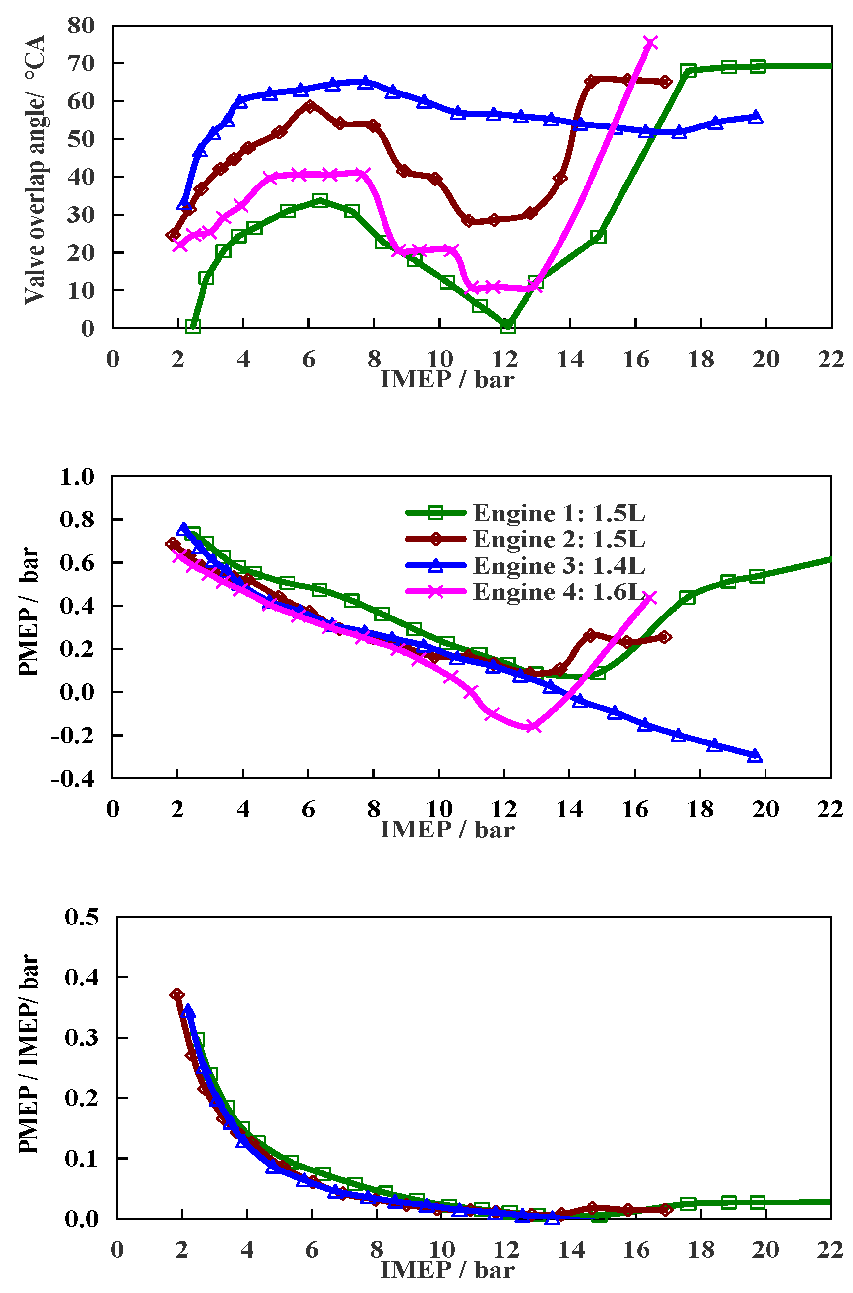
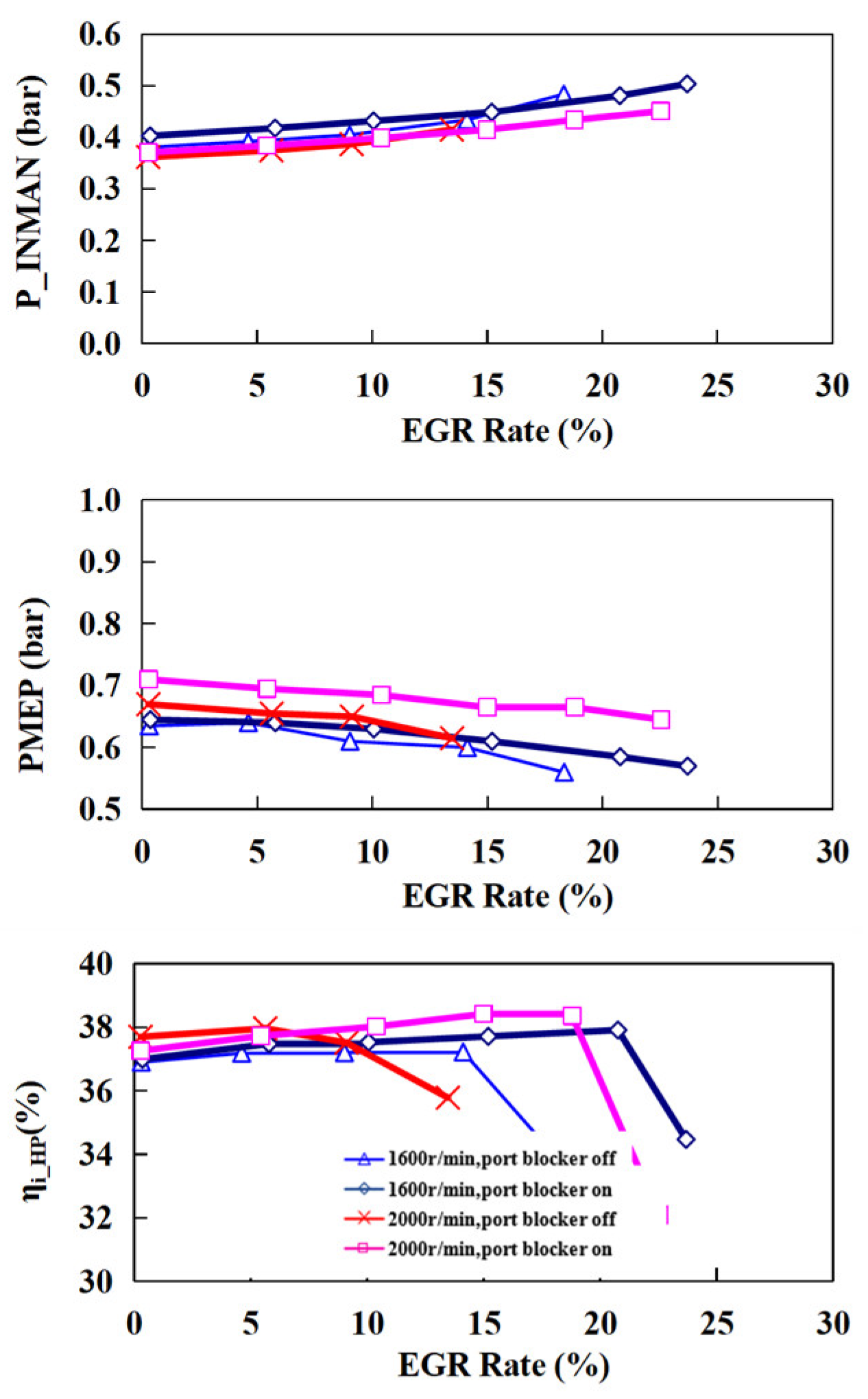
2.2. Portion of Pumping Losses over Indicated Work: PMEP/IMEPHP

As shown in Equation (1), the brake specific fuel consumption rate BSFC is also affected by the portion of pumping losses over the indicated work-PMEP/IMEPHP: the higher is it, the smaller the term 1-PMEP/IMEPHP is, and the higher the BSFC value will be.
Today, optimization of VVT is considered an effective way to reduce pumping losses. This did show a certain degree of PMEP reduction with increased valve overlap from Engine #1, as shown in Figure 6. However, the effect of reduction in the PMEP/IMEPHP team is very limited, being in the range of 1–2%, as also shown in Figure 6. This means, in the variation range of conventional VVT, the potential to reduce the PMEP losses via VVT optimization is very limited, although VVT has been demonstrated to have a strong effect on reducing raw emissions while in idle and to increase the full load power.
Another approach for pumping losses reduction is to introduce externally cooled EGR. Depicted in Figure 7 are the measurement results of the intake pressure, the pumping loss PMEP, and the indicated efficiency vs. external EGR rate of a single cylinder testing engine.
As shown in Figure 7, the introduction of externally cooled EGR indeed could increase the intake pressure and reduce pumping loss [18]. However, due to the fact that EGR retards the combustion process, the maximum amount of external EGR a gasoline engine could tolerate is around 20%. Hence, the pumping loss reduction potential through EGR is also very limited. It should be noted though, as shown in Figure 7, that although the introduction of EGR retarded the combustion process, which led to a reduction in EER, the indicated thermal efficiency had shown a tendency of increase rather than decrease. From Equation (2), one may conclude that it must be caused by an increased adiabatic efficiency due to a lower combustion temperature from the increased EGR.

2.3. Portion of Friction Losses over Indicated Work: FMEP/IMEPHP

Equation (1) also demonstrates that the portion of friction losses over indicated work FMEP/IMEPHP has a direct effect on the BSFC. In modern engines, the major components which affect the friction losses, such as the piston, the crankshaft, the valve driving mechanism, the water pump, the oil pump, etc., have a similar structure and type, as well as operation pressure and flowrates across engines [19,20]. If compared under the same operation condition, i.e., the same speed and same load, there is enough reason to believe that the FMEP/IMEPHP item should have the same or similar values across engines; therefore, the measured values under the same operation conditions as one typical engine will be used to represent all the similar engines under the same operating condition. No further discussions of how the FMEP/IMEPHP was chosen will be given.

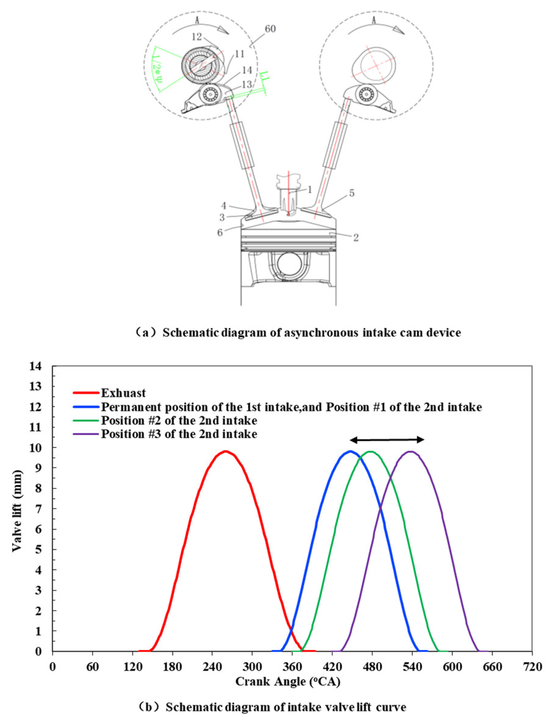
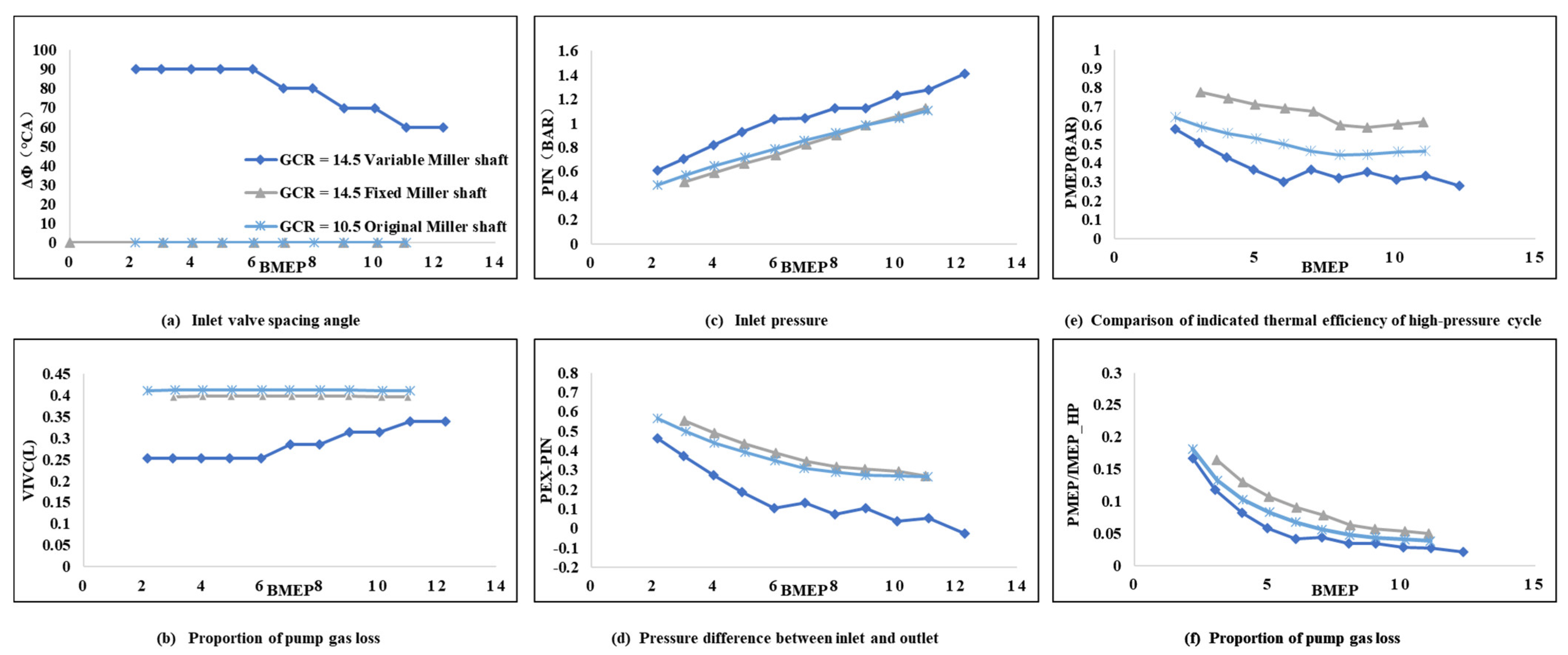
3. Introduction to a Device to Reduce the Pumping Loss and Increase the Expansion Efficiency Simultaneously

This research team had developed a mechanism which could be used to change the intake valve closure timing on a large scale (0–100 °CA). Therefore, the effective cylinder volume and the effective compression ratio ECR can be changed in a wide range [21]. The device was developed to realize the lower compression ratio and the higher expansion ratio Miller Cycle in a gasoline engine. Since the ECR could be changed between 6 and 14.5, this system is also called a variable Miller Cycle system. As shown in Figure 8, this device works on the concept of altering the actual cylinder volume via altering the closure timing of the second intake valve.
Depicted in Figure 8 are the concept drawings of the variable displacement variable compression ratio device controlled by an asymmetric cam. Via altering the interval angles between the two intake valves, the actual cylinder volume, as well as the ECR, are changed accordingly. However, since the effective expansion ratio is only affected by the geometric compression (expansion) ratio and the phasing of the combustion process, and is not directly associated with the intake valve timing, nor the effective cylinder volume when the intake valve closes, this device decouples ECR with EER and could realize a higher EER (for higher thermal efficiency) with a moderate ECR (to avoid knocking and optimize for the combustion phasing), and it is able to adjust ECR in real time.
Shown in Figure 9 are the measurement results of the pumping loss reduction by this device. The closure timing interval angle between the two intake valves, as shown in Figure 9a, are changed according to the engine load. The larger the intake angle interval is, the later the second intake valve closes (the phasing of the first intake valve only changes in a small range), and the smaller the cylinder volume is when both intake valves close, Figure 9b. Since the quantity of fresh charge trapped in the cylinder depends on the multiplication of the cylinder pressure and the volume, for a fixed amount of fresh charge to trap, the smaller the cylinder volume is, the higher the cylinder pressure needs to be, Figure 9c. Thus, the pressure difference between the exhaust to the intake ports is changed accordingly, Figure 9d. Different exhaust over intake port pressure difference results in different pumping losses, Figure 9e. An obvious difference in terms of PMEP/IMEPHP, which directly affects engine BSFC, is then produced, Figure 9f. Figure 9 has clearly demonstrated that this variable cylinder volume device can significantly reduce the pumping loss; for example, at the engine load of 4 bar BMEP, the PMEP/IMEPHP value of the baseline, the fixed ECR 14.5 case and variable ECR case are 0.10, 0.12 and 0.04, respectively.
Depicted in Figure 10 are the testing results of the compression ratio ECR over the in-cylinder thermal efficiency. The settings of the ECR in this test are shown in Figure 10a. Three sets of ECR were tested: two sets of fixed ECR, i.e., geometric compression ratio GCR = 10 and GCR = 14.5, and one set with GCR = 14.5, but with a variable effective compression ratio ECR in the range of 8–13. The adjustment of the effective compression ratio ECR was performed through the asymmetric cam device shown in Figure 8, via changing the interval angles between the two intake valves. The first intake valve closes soon after the gas exchange BDC and its timing seldomly changes. However, the angle interval between the second and the first intake valves changes vs. engine load, as shown in Figure 9a, in the range of 0–100 °CA. The larger the interval angle is, the later the second intake valve closes and the smaller the cylinder volume is at the intake valve closure point, and the smaller the compression ratio, Figure 10a. As the engine load increases, the interval angle reduces, and the effective cylinder volume, as well as the ECR, increases. As the engine load and ECR both increase, the spark timing has to be retarded to avoid knocking. The greater the ECR is, the more the spark timing needs to be retarded, as shown in Figure 10b.
When the engine BMEP is lower than 4 bar, engine knocking is not a concern, and the controlling factor of sparking timing and the CA50 position is for the maximum expansion ratio and the maximum expansion efficiency, Figure 10c. With increases in the engine BMEP, the influences on the knocking tendence of compression ratios become more and more clearer, and the higher the ECR is, the more the spark timing has to be retarded to avoid knocking. Therefore, the ECR has a strong influence on the CA50 position, e.g., at the BMEP = 8 bar, the ECR of the three settings are 14.3, 11.2 and 9.9; the corresponding spark timings are 3 °, 10 ° and 17.5 °CA BTDC; and the CA50 positions are 6.5 °CA, 15.0 °CA and 23.5 °CA ATDC, respectively.
As shown in Equations (4) and (5), EER depends on both the geometric expansion ratio and the phasing of combustion. For the GCR = 14.5 fixed ECR case, although the GER is close to 14, due to the very high ECR, the spark timing and the CA50 position are so much delayed that the EER is only 8.2, which is in the same level as the GCR = 10 baseline, Figure 10d. For the GCR = 14.5 variable ECR case, at BMEP = 8.0 bar the ECR is 11.2, and is higher than the baseline, and therefore the spark timing and CA50 position are also retarded. However, the GER is close to 14, and while the delay of the spark timing and the CA50 position were not as severe as the ECR = 14.3 case, the combined EER is 9.4, i.e., higher than GCR = 10 baseline, and the GCR = 14.5 and ECR = 14.3 case.
The in-cylinder high pressure cycle thermal efficiency, as shown in Equation (3), depends closely on both ECR and EER, which are compared in Figure 10e as the high-pressure cycle indicated thermal efficiency ( η i _ H P ) of the three compression ratio settings. When the engine load is less than 6.0 bar, the GCR = 14.5 fixed ECR case has much higher ECR and EER than the other two cases, therefore it produces much higher η i _ H P . Along with further increases in engine load, the higher ECR case results in a significant drop in EER, till the EER drops to be lower than the lower GCR cases. Then, although the ECR is significantly higher than in other cases, the η i _ H P is lower than other two cases. This indicates that the in-cylinder thermal efficiency is much more sensitive to EER than ECR. When the ECR is greater than a certain value, e.g., 8, a further increase in ECR itself only induces a small increase in η i _ H P , but may cause a drop in EER and η i _ H P .
Shown in Figure 11 are the various engine performance terms comparing the three ECR cases. Depicted in Figure 11a are the ECR setting in the tests: there are two fixed ECR settings, corresponding to GCR = 10 and GCR = 14.5 cases, respectively, and also one variable ECR setting of GCR = 14.5.
For the GCR = 14.5 variable compression ratio case, in order to reduce the pumping losses at small load, the valve timing of the second intake valve is significantly delayed, the effective cylinder volume is reduced, as well as the pumping losses. Along with the load increase, the cylinder volume at intake valve closure has to increase to accommodate the required fresh charge. Thus, the effective compression ratio increases accordingly. The pumping losses drop automatically with increased engine load and eventually become negligible. On the other hand, the influences of ECR on EER, and further the in-cylinder thermal efficiency in return, eventually take the leading role.
Therefore, in Figure 11, although the GCR = 14.5 fixed ECR case has a much higher ECR and the same level EER as the GCR = 14.5 variable ECR case, the former has higher in-cylinder thermal efficiency. On the other hand, its actual cylinder volume at IVC is much higher, with a much lower intake pressure and higher pumping losses, Figure 11b. The overall BSFC of the former is higher than the latter, as shown in Figure 11f. Obviously, at light load, the gain in efficiency from higher ECR could not compensate the pumping losses from the higher cylinder volume (and lower intake pressure). At a medium to higher load, the PMEP/IMEPHP term is already very low and therefore has very little influence on the BSFC. In those cases, the in-cylinder thermal efficiency takes the leading role on fuel economy; a higher ECR produces lower thermal efficiency and a higher BSFC because it causes lower EER.
The above analysis indicates that, in order to achieve high in-cylinder thermal efficiency, EER should be as high as possible. However, to achieve high EER, not only the GCR should be high, but also the phasing of the combustion process should be as close to TDC as possible. This means the compression pressure and temperature should not be too high, or the ECR should not exceed a value to impact the phasing of the combustion process. That is to say, the ECR should be moderate: too low of a value would result in too low an in-cylinder thermal efficiency, while too high of a value could produce a lower thermal efficiency due to lower EER.
Shown in Figure 12 are the testing results of an asymmetric cam-driven variable ECR mechanism designed on the thoughts above. First of all, the GCR of the engine was increased from 10.5 baseline to 12 via modifying the shape of the piston top (to reduce the crevice volume). A GCR of 12, rather than 14.5, was chosen. The reason for this was that, as shown in Figure 11, a high GCR will result in a high ECR at higher loads, which in-return will result in a very late spark timing and a lower EER; engine thermal efficiency would suffer and the advantage of a high GCR would disappear. The interval angle of the two intake valves is modified in a way that, as shown in Figure 12a, the cylinder volume at IVC is always lower than the baseline engine, Figure 12b. At a light load, the reduced cylinder volume results in a lower PMEP/IMEPHP, Figure 12c. On the other end, the reduced cylinder volume at IVC also results in lower ECR, Figure 12d. The reduced ECR then produces lower compression pressure and temperature, the knocking tendence is reduced and the CA50 position is then advanced, Figure 12e. The increased GCR from 10.5 to 12 and the advanced combustion phasing both contribute to the increase in EER, Figure 12f. What should be mentioned is that the increment in EER exceeds the increment in GCR (from 10.5–12). This is due to the advancement in the combustion phasing. Although the ECR of the GCR = 12 case is lower than the GCR = 10.5 baseline, Figure 12d, the EER of the former is higher than the latter all the way, thus a higher thermal efficiency is produced, as shown in Figure 12g. Via utilizing a smaller effective cylinder volume to reduce the pumping losses at a light load, and a moderate ECR but a high EER at medium to high loads, the thermal efficiency of the engine is significantly improved at all loads, with a significant drop in BSFC, as shown in Figure 12h.
The above results show that, under low to medium loads, there is a best compromise between pumping loss and in-cylinder expansion efficiency vs. the intake valve closing timing (effective cylinder volume). While in the medium to heavy loads, there exists a problem of the optimal combination of ECR and EER. Obviously, this is an optimization issue of multiple performance objectives, and multiple variables with multiple constraints. Due to the length limitation of this paper, no more discussion will be provided and it will be analyzed in a separate article.

4. Conclusions

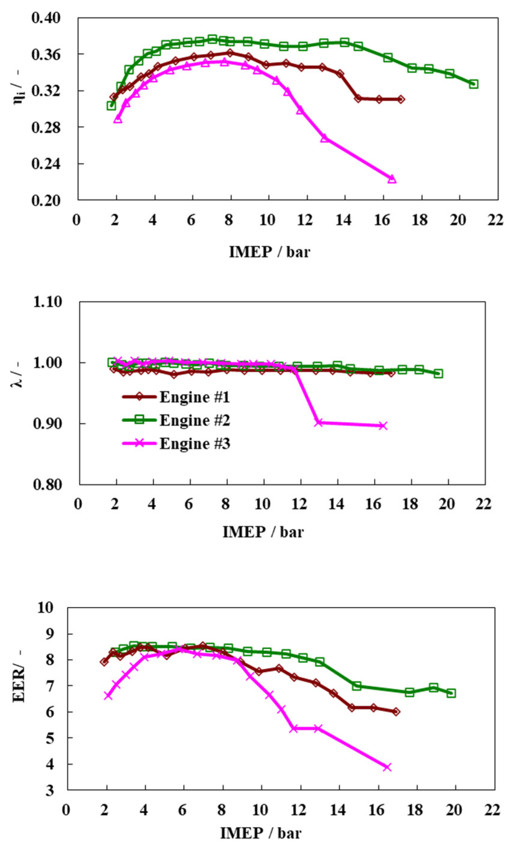
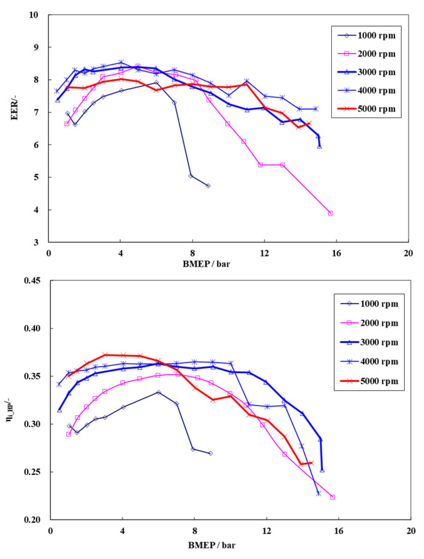
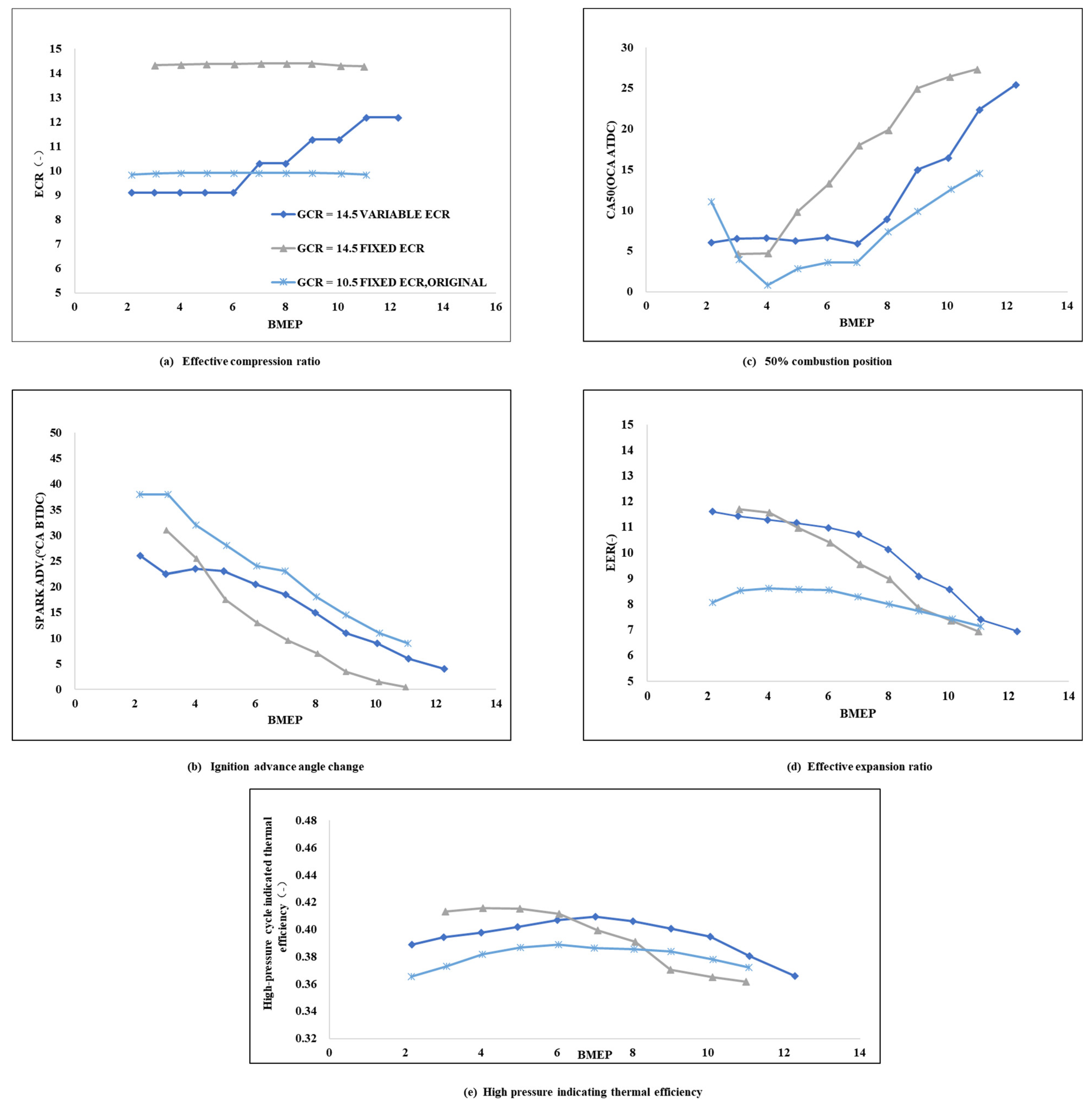
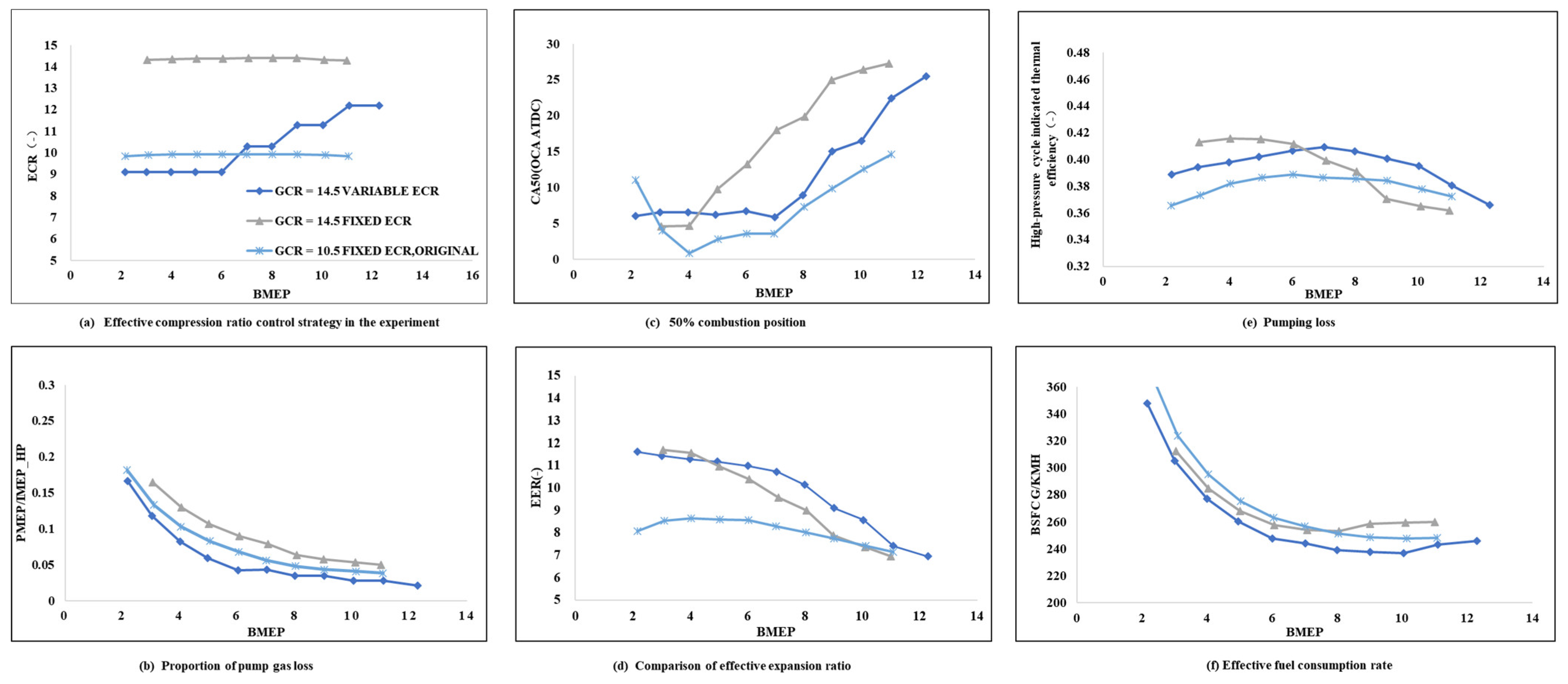
  • The pumping losses at a low to medium load can be significantly reduced by reducing the effective cylinder volume at IVC. However, the effective compression ratio will be reduced too which would result in a drop of in-cylinder thermal efficiency. The overall results of BSFC depends on the engine load; at a low load the pumping loss reduction takes the leading role, while in the medium to high load, the expansion efficiency takes the leading role and ECR/EER becomes more important on engine BSFC;
  • Although both ECR and EER have influences on the in-cylinder thermal efficiency, EER’s influence is much more significant. A low ECR but a high EER combination produces higher thermal efficiency than a high ECR but a low EER case;
  • Compression pressure and temperature are both influenced by ECR; the formers will then affect the phasing of the combustion. In this way, ECR has a strong indirect influence on EER. Too high an ECR may result in a much later combustion phase, a lower EER and lower thermal efficiency. In addition, a high GCR but moderate ECR combustion system is more favorable to achieve high engine efficiency.

Author Contributions

Conceptualization, H.Y. and L.Z.; methodology, J.L. and D.S.; software, J.F.; validation, H.Y., D.S. and L.Z.; formal analysis, J.L. and Z.Y.; investigation, H.Y.; resources, D.S.; data curation, L.Z.; writing—original draft preparation, H.Y.; writing—review and editing, J.L.; visualization, J.F.; supervision, J.F.; project administration, J.L.; funding acquisition, D.S. All authors have read and agreed to the published version of the manuscript.

Funding

This research is partially funded by the Jingping Liu: Chinese National Natural Science Funding Program; #51776061; Zhipeng Yuan: Hunan Education Department Science Research project; #19B585.

Data Availability Statement

Not applicable.

Conflicts of Interest

The authors declare no conflict of interest.

Glossary

Nomenclature
η i _ H P high-pressure cycle indicated thermal efficiency
H u low heating value of fuel [J/kg]
λ excess air coefficient
η c o m b combustion efficiency
η a d i adiabatic efficiency
η e x p d expansion efficiency
p i n intake pressure
γ polytropic exponent (-)
p e x exhaust pressure
H R R θ normalized heat release rate [1/(°CA)]
E R θ instantaneous expansion ratio [-]
θ crank angle [°CA]
V E V O θ cylinder volume at the exhaust valve opening
V θ cylinder volume at the current combustion phase
Abbreviations
GDIgasoline direct injection
VVTvariable valve timing
EGRexhaust gas recirculation
ECReffective compression ratio
EEReffective expansion ratio
IVCintake valve closing
IVOintake valve opening
EVCexhaust valve closing
EVOexhaust valve opening
VVLvariable valve lift
ICEInternal combustion engine
BSFCbrake specific fuel consumption
ICEInternal combustion engine
SOCstart of combustion
EOCend of combustion
TDCtop dead center
BDCbottom dead center
PMEPpumping mean effective pressure
FMEPfriction mean effective pressure

References

  1. Lou, Z.; Zhu, G. Review of Advancement in Variable Valve Actuation of Internal Combustion Engines. Appl. Sci. 2020, 10, 1216. [Google Scholar] [CrossRef]
  2. Yu, X.; Zhao, Z.; Huang, Y.; Shi, W.; Guo, Z.; Li, Z.; Du, Y.; Jin, Z.; Li, D.; Wang, T. Experimental study on the effects of EGR on combustion and emission of an SI engine with gasoline port injection plus ethanol direct injection. Fuel 2021, 305, 121421. [Google Scholar] [CrossRef]
  3. Zou, P.; Liu, J.; Zhou, X.; Chen, Z.; Luo, B.; Shen, D.; Duan, X.; Fu, J. Effect of a novel mechanical CVVL system on economic performance of a turbocharged spark-ignition engine fuelled with gasoline and ethanol blend. Fuel 2020, 263, 116697. [Google Scholar] [CrossRef]
  4. Benedikt, K.; Drexler, G.; Eder, T.; Eisenkoelbl, M.; Luttermann, C.; Schleusener, M. Further development of BMW’s fully-variable valve control system valvetronic. MTZ Worldw. 2005, 66, 10–13. [Google Scholar] [CrossRef]
  5. Wittek, K.; Geiger, F.; Andert, J.; Martins, M.; Cogo, V.; Lanzanova, T. Experimental investigation of a variable compression ratio system applied to a gasoline passenger car engine. Energy Convers. Manag. 2019, 183, 753–763. [Google Scholar] [CrossRef]
  6. Sun, X.; Xie, M.; Zhou, F.; Wu, X.; Fu, J.; Liu, J. Hierarchical evolutionary construction of neural network models for an Atkinson cycle engine with double injection strategy based on the PSO-Nadam algorithm. Fuel 2023, 333, 126531. [Google Scholar] [CrossRef]
  7. Chen, B.; Zhang, L.; Han, J.; Zhang, Q. A combination of electric supercharger and Miller Cycle in a gasoline engine to improve thermal efficiency without performance degradation. Case Stud. Therm. Eng. 2019, 14, 100429. [Google Scholar] [CrossRef]
  8. Li, T.; Gao, Y.; Wang, J.; Chen, Z. The Miller cycle effects on improvement of fuel economy in a highly boosted, high compression ratio, direct-injection gasoline engine: EIVC vs. LIVC. Energy Convers. Manag. 2014, 79, 59–65. [Google Scholar] [CrossRef]
  9. Huang, Z.-M.; Shen, K.; Wang, L.; Chen, W.-G.; Pan, J.-Y. Experimental study on the effects of the Miller cycle on the performance and emissions of a downsized turbocharged gasoline direct injection engine. Adv. Mech. Eng. 2020, 12, 1687814020918720. [Google Scholar] [CrossRef]
  10. Xu, J.; Guo, T.; Feng, Y.; Sun, M. Numerical investigation of Miller cycle with EIVC and LIVC on a high compression ratio gasoline engine. Sci. Prog. 2021, 104, 00368504211023640. [Google Scholar] [CrossRef] [PubMed]
  11. Millo, F.; Accurso, F.; Zanelli, A.; Rolando, L. Numerical investigation of 48 V electrification potential in terms of fuel economy and vehicle performance for a lambda-1 gasoline passenger car. Energies 2019, 12, 2998. [Google Scholar] [CrossRef]
  12. Wang, Y.; Zu, B.; Xu, Y.; Wang, Z.; Liu, J. Performance analysis of a Miller cycle engine by an indirect analysis method with sparking and knock in consideration. Energy Convers. Manag. 2016, 119, 316–326. [Google Scholar] [CrossRef]
  13. Pandey, J.K.; Kumar, G. Effect of variable compression ratio and equivalence ratio on performance, combustion and emission of hydrogen port injection SI engine. Energy 2021, 239, 122468. [Google Scholar] [CrossRef]
  14. Xia, Y.; Li, Y.; Liao, C.; Liu, J.; Wang, S.; Qiao, J.; Zhang, S. On the quantitative relationship of the in-cylinder heat to work conversion process of natural gas spark ignited engine under steady state and transient operation conditions. Energy 2021, 221, 119607. [Google Scholar] [CrossRef]
  15. Yuan, Z.; Liu, J.; Fu, J.; Liu, Q.; Wang, S.; Xia, Y. Quantitative analysis on the thermodynamics processes of gasoline engine and correction of the control equations for heat-work conversion efficiency. Energy Convers. Manag. 2017, 132, 388–399. [Google Scholar] [CrossRef]
  16. Modiyani, R.; Kocher, L.; Van Alstine, D.; Koeberlein, E.; Stricker, K.; Meckl, P.; Shaver, G. Effect of intake valve closure modulation on effective compression ratio and gas exchange in turbocharged multi-cylinder engines utilizing EGR. Int. J. Engine Res. 2011, 12, 617–631. [Google Scholar] [CrossRef]
  17. Niu, Q.; Sun, B.; Zhang, D.; Luo, Q. Research on performance optimization and fuel-saving mechanism of an Atkinson cycle gasoline engine at low speed and part load. Fuel 2020, 265, 117010. [Google Scholar] [CrossRef]
  18. Siqueira Mazzaro, R.; de Morais Hanriot, S.; Jorge Amorim, R.; Américo Almeida Magalhães Júnior, P. Numerical analysis of the air flow in internal combustion engine intake ducts using Herschel-Quincke tubes. Appl. Acoust. 2020, 165, 107310. [Google Scholar] [CrossRef]
  19. Wróblewski, P.; Iskra, A. Problems of Reducing Friction Losses of a Piston-Ring-Cylinder Configuration in a Combustion Piston Engine with an Increased Isochoric Pressure Gain. In SAE Technical Paper; SAE International: Warrendale, PA, USA, 2020. [Google Scholar]
  20. Wróblewski, P. Reduction of friction energy in a piston combustion engine for hydrophobic and hydrophilic multilayer nanocoatings surrounded by soot. Energy 2023, 271, 126974. [Google Scholar] [CrossRef]
  21. Shen, D.Z.; Liang, J.C. Strong Eddy Current Variable Miller Cycle Internal Combustion Engine. CN114412639A, 29 April 2022. [Google Scholar]
Figure 1. The relationship between combustion efficiency with excessive air/fuel ratio, from all the partial load data of Engines #1,2,3.
Energies 16 04480 g001
Figure 2. Schematic diagram of experimental setup for engine bench testing.
Energies 16 04480 g002
Figure 3. High pressure cycle adiabatic efficiency vs. engine speed and load, from Engine #4 of Table 1.
Energies 16 04480 g003
Figure 4. Variation of high-pressure cycle indicated thermal efficiency vs. excessive air/fuel ratio, EER and engine load, 2000 r/min, multiple engines.
Energies 16 04480 g004
Figure 5. Variation of high-pressure cycle-indicated thermal efficiency vs. engine speed, load and EER, typical gasoline engine, engine #4.
Energies 16 04480 g005
Figure 6. Variation of valve overlap, PMEP and PMEP/IMEPHP vs. IMEP for engine #1 to #4 at 2000 r/min.
Energies 16 04480 g006
Figure 7. Influences on the intake pressure, pumping losses and indicated thermal efficiency of externally cooled EGR, 1600 r/min and 2000 r/min, engine #5.
Energies 16 04480 g007
Figure 8. Concept drawing of an asymmetric cam controlled variable displacement, variable compression ratio device.
Energies 16 04480 g008
Figure 9. Testing results of pumping losses vs. variable cylinder volume, 2000 r/min, based on the modification of engine #6.
Energies 16 04480 g009
Figure 10. Testing results of the In-Cylinder Thermal Efficiency vs. compression ratio, based on the modification of engine #6.
Energies 16 04480 g010
Figure 11. The overall influences on engine BSFC of variable displacement and variable CR, 2000 r/min partial load, based on the modification of engine #6.
Energies 16 04480 g011
Figure 12. Validation of performance improvement for an asymmetric cam-driven variable ECR engine, based on the modification of engine #6.
Energies 16 04480 g012
Table 1. Specifications of engines tested and analyzed in this paper.
ItemEngine #1Engine #2Engine #3Engine #4Engine #5Engine #6
Engine typeIn-line four-cylinder, four strokeIn-line four-cylinder, four strokeIn-line four-cylinder, four strokeIn-line four-cylinder, four strokeSingle cylinder, four strokeIn-line four-cylinder, four stroke
Displacement (L)1.51.51.41.60.671.5
Bore (mm)767974.579.79873.5
Stroke (mm)82.676.58081.189.388
Connecting rod length (mm)133.2133.2132.8138.5152.7141.51
Compression ratio (-)101010.59.510.510.5
Intake typeTurbocharged, Inter-cooled, Dual VVTTurbocharged, Intercooled, Dual VVTTurbocharged, Inter-cooled, Dual VVTTurbocharged, Inter-cooled, Dual VVTNaturally AspiratedTurbocharged, Inter-cooled, Dual VVT
Inject typeGDIGDIGDIGDIGDIGDI
Rated power (kW)12513396140/132
Maximum torque (N·m)230240225240/300
Table 2. The specifications of main test instruments and equipment.
Equipment NameTypePrecision
AVL electric dynamometerINDY S22-2/0525-1BV-1Torque: ±0.5% F.S
Speed: ±1 r/min
Dynamometer control systemPUMA OPEN1.4.1±0.5% F.S
Fuel consumption meter7351 CST±0.12% F.S
Data acquisition systemPUMAResolution: 15 Bit
Sampling rate: 1–200 Hz
Fuel temperature control system753C±2 °C
Coolant temperature control system553 CONSYSCOOL 553-200±2 °C
Oil temperature control system554 CONSYSLUBE 554±2 °C
Mass air flow meterTP16A.00±1% F.S
λ analysis meterETAS±0.01
Combustion analyzerINDISET ADVANCED PLUS/
Disclaimer/Publisher’s Note: The statements, opinions and data contained in all publications are solely those of the individual author(s) and contributor(s) and not of MDPI and/or the editor(s). MDPI and/or the editor(s) disclaim responsibility for any injury to people or property resulting from any ideas, methods, instructions or products referred to in the content.

