1. Introduction
The continuous development of space technology has led to the emergence of several industries, including space tourism, space breeding, space biopharmaceuticals, and space microgravity environmental testing, which have brought significant benefits to society and the economy. However, as space exploration progresses, spacecraft are exposed to increasing thermal loads, posing challenges to spacecraft design, launch costs, and system stability. Spacecraft thermal management systems are critical to maintaining a stable and suitable internal environment for the crew, equipment, samples and long-term food storage while withstanding extreme ambient temperatures [
1]. On the Moon, for example, the steady-state temperature at noon can be close to 390 K, which presents a significant challenge to heat dissipation [
2]. Therefore, effective thermal control technologies are needed to ensure the success of future space missions. As space missions become more demanding, spacecraft thermal management systems face challenges such as higher heat flux, improved temperature control, and more compact and lightweight designs. To meet these challenges, theoretical calculations and analysis of heat transfer processes on surfaces with complex geometries have been explored for enhanced heat transfer [
3]. Existing aerospace thermal control technologies are not fully capable of meeting these requirements, and new aerospace thermal control technologies need to be further explored. The selection of new bearings and improvements in lubrication methods have been explored, which contribute to the performance and stability of the system [
4]. One such promising solution is the vapor compression heat pump system [
5], which utilizes the latent heat of vaporization during the phase change of the refrigerant to achieve strong heat-dissipation capabilities and a high coefficient of performance (COP). In addition, by raising the condensation temperature using a compressor, the system can raise the heat discharge temperature of the radiator, thus significantly reducing the radiator area and mass. This makes the vapor compression heat pump system highly suitable for aerospace applications.
Despite the theoretical advantages of vapor compression heat pumps in space use, there are numerous operational challenges compared to other thermal control technologies. These challenges include the effect of microgravity on compressor lubrication and performance, the influence on evaporation and condensation heat transfer processes, continuous gas–liquid separation, and the stability of vapor compression heat pump systems. However, the technological readiness level of vapor compression heat pump remains relatively low, and its use in the aerospace field is limited by the difficult and expensive testing conditions in microgravity environments, as well as the lengthy demonstration period required in aerospace. In particular, the published literature reports that only one vapor compression system in orbit is currently operational on the International Space Station. A comprehensive review of the historical application of vapor compression heat pumps in microgravity environments has been provided by Brendel et al. [
6]. The authors reviewed the development of space vapor compression refrigeration over the past 40 years, summarized performance data, and identified challenges that need to be addressed in future research, including investigating gas-liquid separation and the use of oil-free compressors in microgravity [
7].
Numerous scholars have explored the design and performance of new aerospace compressors in two main directions: the development of oil-free lubricated compressors, and the microgravity adaptation of compressors utilizing lubricating oil, along with gas–liquid separation studies. In small aerospace vapor compression heat pumps, oil-free compressor systems primarily focus on system performance analysis. In contrast, systems equipped with oil-lubricated compressors prioritize refrigerant/lubricant mixing flow and heat transfer characteristics, including lubricant deposition, lubricant’s impact on heat transfer, and gas–liquid separation.
Table 1 lists the studies of compressors in different orientations and their results, which changed the orientation of the compressor components rather than the entire vapor compression system. The effect of gravity on compressor performance is mainly related to the lubricant; however, there is little literature discussing the effect of gravity on the lubricant, such as the oil circulation rate.
Bell et al. [
13] optimized a heat pump system for satellite cooling with an oil-free scroll compressor and R152a refrigerant for the future spacecraft thermal control process with increased heat flux, and investigated the effect of system temperature distribution and heat load on COP. Rong et al. [
14] applied an aerostatic bearing to a compressor and experimentally verified the aerostatic bearing-rotor gravity independence, which can be applied as a novel lubrication technique in vapor compression heat pumps. Murphy et al. [
15] developed a high-head, two-piston oil-free reciprocating compressor with compression ratios between 3 and 7 for a lunar vehicle-mounted heat pump for the extreme temperature environment in which the lunar rover is located. The design cooling capacity of the compressor was 100 W. Skipworth et al. [
16] explored the application of an oil-free scroll compressor in a vapor compression heat pump system from the perspective of storing food for a long-term space mission, using parabolic flight for microgravity tests, and achieved enhanced temperature control and cooling capacity of the refrigerated cabinet by microgravity adaptation of the compressor. In this paper, a miniature rolling rotor compressor is selected, which has the advantages of high performance, low energy consumption, small size, light weight and low vibration compared with other compressors. Due to the difficulty and high cost of access to microgravity environment testing, an inclination angle test stand can be used to test vapor compression heat pumps in a ground environment. Variable-angle test stands have emerged as a cost-effective and easily implementable testing method that has gained significant recognition in microgravity two-phase flow investigations, providing a solution to these challenges. While replicating the microgravity environment is unfeasible, the effect of gravity on system performance can be evaluated by adjusting the test stand angle during ground-based experiments. The system or component’s adaptability to microgravity conditions is indicated by the consistency of results across various test angles, implying gravity-independence. Moreover, the variable-angle test stand surpasses other testing methodologies due to its lack of spatial limitations and ability to operate in real-time, thereby facilitating dynamic adjustment of system parameters, maintenance, and optimization. As a result, it plays a crucial role in the comprehensive exploration of aerospace vapor compression heat pump systems. Grzyll and Cole [
17] tested a refrigerated centrifuge for the International Space Station in six orientations using a modified oil-free compressor. The orientation testing results proved that the system could operate in six gravity orientations, but the cooling capacity and COP of the system were decreased by 19~20% compared to the original oil-lubricated hermetic reciprocating compressor. Domitrovic et al. [
18] tested a vapor compression system with an oil-lubricated scroll compressor, and the steady-state results showed that the system was insensitive to orientation changes. However, the experiments did not further explore the effect of orientation on the lubricant, which is important for aerospace applications of systems containing lubricants.
Brendel et al. [
19,
20] built a ground-based inclination angle test rig for a vapor compression heat pump system to study the effect of gravity direction change on system performance, and proposed an inclination dependence indicator to describe the magnitude of the effect of gravity direction on system performance. The results showed that the inclination dependence indicator decreases with increasing refrigerant mass flux. In the inclination angle range from 90° to 225°, vapor mass flow oscillations were observed in the suction line and the oscillations decreased with increasing mass flow. The system instability was also observed for the ground inclination experiments in specific cases. In addition, the effect of orientation on the stability of the cycle at different mass flow rates, as well as the effect of system performance such as cooling capacity, was further investigated by inclination angle variation.
In the above-mentioned literature, oil-free compressors are basically used to avoid the problem of gas–liquid separation in a microgravity environment. However, compared to oil-free compressors, compressors employing lubricating oil usually have greater volumetric efficiency, typically higher mechanical efficiency, and longer service life due to the presence of a lubricating film that reduces intermetallic friction losses, which can enhance refrigeration capacity and reduce system energy consumption. Therefore, the study of aerospace applications of compressors employing lubricating oil remains of great importance. By studying the lubricant distribution and oil return characteristics of the system, compressor aerospace applications in microgravity environment can be verified and optimized.
Youbi-Idrissi et al. [
21] reviewed studies on lubricants in refrigeration systems and analyzed the effect of lubricants on compressors, capillaries, and evaporators. Marsh et al. [
22] presented the application of synthetic oils in HFC refrigerants, where viscosity and solubility are two important factors in the evaporator, due to the evaporation of the refrigerant which increases the viscosity of the liquid phase affecting the oil return, while in the compressor the lubricant dissolves the refrigerant causing a decrease in viscosity affecting the lubrication performance. In addition, Mermond et al. [
23] presented a series of methods for calculating the physical properties of lubricant-refrigerant mixtures. Shen and Groll [
24,
25] reviewed the influence of lubricants on refrigerant heat transfer and pressure drop, including pool boiling and flow boiling, as well as the condensation process and pressure drop.
Ma et al. [
9] addressed the problem of difficult gas–liquid separation in a microgravity environment by removing the gas–liquid separator and modifying the compressor for microgravity suitability by using a direct refrigerant/lubricant mixture. Based on this, a test bench was built to study the system performance under upright and inverted modes of the compressor, and the results showed that the inverted performance of the compressor was better than upright under specific operating conditions. In addition, the developed vapor compression heat pump system was creatively tested in weightlessness through bungee platform free fall, a relatively economical method, and through analysis of temperature data it was found that weightlessness reduced the evaporative heat transfer performance while enhancing the condensing heat transfer performance. In the subsequent study, the mixed flow and heat transfer model of refrigerant and lubricating oil in the evaporator was established, and the effect of heat flux on the system performance in normal gravity and microgravity was investigated by simulation [
26].
Ye et al. [
27] addressed the difficulties of gas–liquid separation and compression deterioration of compressors in a microgravity environment, adopted a compressor microgravity suitability modification method by removing the gas–liquid separator and fully mixing the refrigerant/lubricant, and developed a flow model inside the compression chamber to investigate the effects of gravity and lubricant volume fraction on lubricant distribution and flow characteristics. The results show that more lubricant is deposited in the compression chamber and the outlet lubricant volume fraction is reduced in the microgravity environment compared to normal gravity. The simulation results of exhaust temperature were compared with the experimental values and the maximum difference was 9.16%
Most studies on vapor compression heat pumps for aerospace applications utilize oil-free compressors to avoid complications arising from the gas–liquid separation of lubricant and refrigerant gas in microgravity. Nonetheless, compressors with lubricating oil exhibit the potential to reduce leakage and friction losses, while offering larger refrigeration capacity and higher compression efficiency. In ground environments, research on vapor compression heat pumps and compressors is well-established. In microgravity environments, however, it is crucial to ascertain whether the lubricant in the compressor can achieve lubrication and sealing, and whether the lubricant in the system can be suitably returned to the compressor. The study of the effect of gravity on lubricants is of great importance. Existing research on lubricants shows that too much lubricant can reduce COP, but a small amount can help optimize system efficiency. However, research on the flow heat transfer characteristics of refrigerant and lubricating oil, as well as the compressor oil return characteristics, remains sparse in the context of vapor compression heat pump aerospace applications, particularly in relation to the variation of oil circulation rate and its effect on system performance. Previous research on compressors has used hoses to allow the compressor to change the tilt angle individually. However, tilting the entire vapor compression heat pump gives a better indication of the effect of gravity on system performance than tilting the compressor alone, because the effect of gravity on other components of the system is taken into account. However, there is no published literature that examines a tilting test stand for a vapor compression heat pump with an oil-lubricated compressor that also gives the effect of gravity on oil circulation rate and system performance. This is not conducive to the development of more efficient vapor compression heat pump systems.
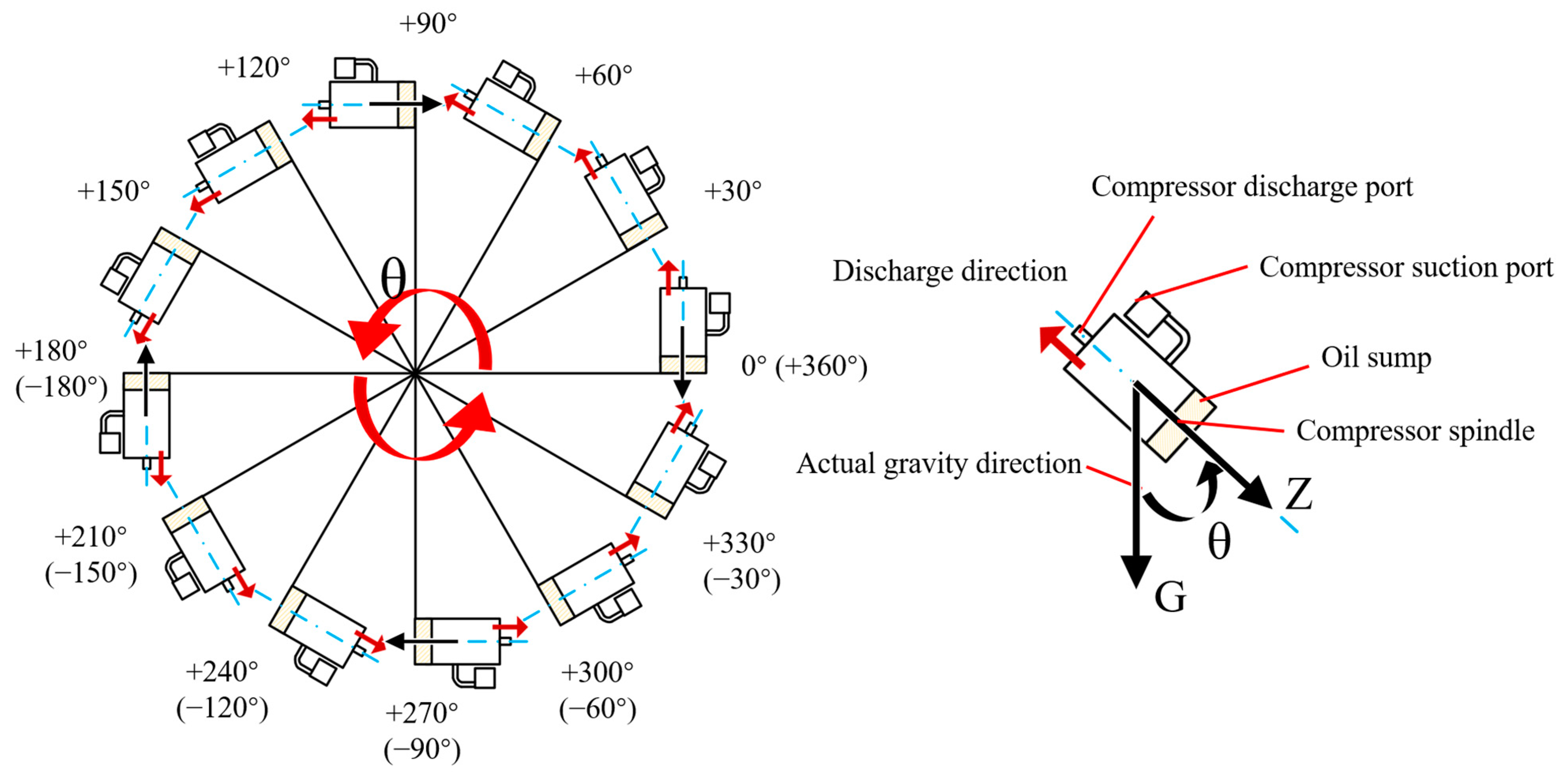
To investigate the effect of gravity on the performance of a vapor compression heat pump system and oil circulation rate, this paper designs and constructs a variable angle test stand for ground testing of vapor compression heat pumps. The angle of the test stand can be modified by turning a hand wheel, thereby allowing changes in the angle between the heat pump system and the direction of gravity. This enables the study of the effect of gravity on the performance and stability of the vapor compression heat pump system, the change of oil circulation rate (OCR), and the correlation between OCR and system performance. Performance tests were conducted at different inclination angles, including the effects of gravity on evaporating temperature, condensing temperature, compressor discharge temperature, changes in system subcooling and superheating, and COP of the system. This paper is an addition to the literature on inclination angle testing of vapor compression heat pumps at the whole-system level. The variation of oil circulation rate with inclination angle in a vapor compression heat pump system was collected. The relationship between the oil circulation rate and the system performance was investigated. The results showed that the vapor compression heat pump system can operate stably under varying inclination angles. The system flow rate displayed a sinusoidal trend as the inclination angle increased, with a deviation of 10.7% relative to the initial flow rate. The evaporating temperature, condensing temperature, and compressor discharge temperature exhibited symmetrical relationships with respect to the inclination angle of 180°. The oil circulation rate was found to be gravity-sensitive and remained high at inclination angles between 90 and 270°. Moreover, the oil circulation rate displayed good consistency with variations in subcooling and superheating. However, an increase in oil circulation rate resulted in a reduction in the system COP. At the inclination angle of 90°, the compressor had the maximum COP of 5.5.
3. Results
During the experiment, 150 g of refrigerant is charged in the system, the compressor speed is set to 2600 rpm, the electronic expansion valve is opened at 60 pulses, and the ceramic heating sheets are supplied with 322 W power. The experiment was conducted at 13 angles, starting from 0° and continuing in increments of 30° up to 360°. The effect of gravity on the system’s flow rate, oil circulation rate, temperature distribution, and COP was investigated during the experiment’s variation of inclination angle.
3.1. Effect of Gravity on Flow Rate
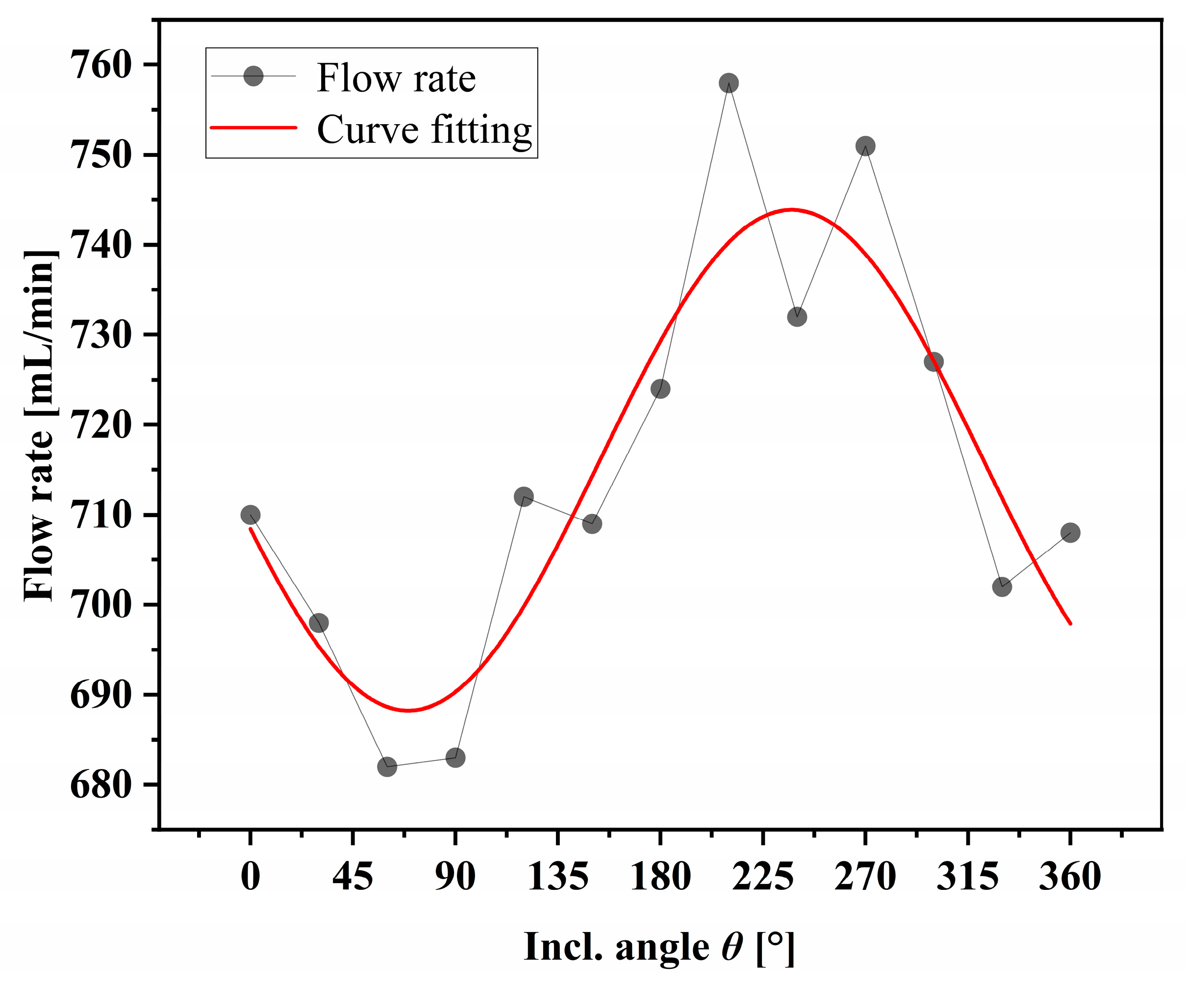
Figure 7 shows the effect of the inclination angle on the system flow rate. The system flow rate data indicate a sinusoidal trend as the inclination angle increases. The flow rate varies in the range of 682 to 758 mL/min as the inclination angle varies from 0 to 360°, which is a 10.7% change relative to the initial flow rate. The volume flow rate at 0° was 710 mL/min, while the volume flow rate at 360° was 708 mL/min. After the test stand was turned over at 360°, the flow rate of the system roughly returned to the initial state. From 0 to 90°, the system flow rate decreases with the increase in the inclination angle, and reaches the minimum value near 90°. Subsequently, at around 90~270°, the system flow rate shows an increasing trend with the increase in the inclination angle, and reaches the maximum value near 270°. Beyond 270°, the system flow rate decreases again as the inclination angle increases.
The variation in system flow may be associated with the system pressure difference and refrigerant deposition due to the relative position of the condenser in the system. From 0 to 90°, the evaporating pressure increased as the angle increased, while the condensing pressure remained relatively stable. The resulting decrease in pressure difference led to a reduction in the system flow rate. During system operation, refrigerant liquid mainly deposits in the condenser. At 0°, the condenser is in the same horizontal plane as the entire system. As the angle increases, the condenser position decreases, while the compressor and evaporator positions increase, resulting in a decrease in the system flow rate. At an inclination of 90°, the condenser is at its lowest point, and more refrigerant deposits in the condenser due to gravity, leading to a system flow rate of 682 mL/min. From 90 to 270°, the condenser position gradually rises, and the system flow rate increases accordingly. At 180°, the flow rate slightly increases when the system is inverted compared to that at 0°. Subsequently, in the range of 270 to 360°, the condenser height decreases, leading to a decrease in the flow rate, which essentially returns to the initial state level at 360°.
The effect of gravity on the flow rate of a vapor compression heat pump system is evident, as shown by the sinusoidal trend observed in the flow rate data as the inclination angle increases. This can be attributed to changes in the direction and magnitude of the gravitational force, which affect the flow and deposition of refrigerant in the piping and heat exchanger, consequently leading to changes in pressure and flow rate. The changes in refrigerant flow rate, in turn, cause temperature variations at different points in the system, affecting the system’s superheat and subcooling. Additionally, the study reveals that the system’s flow rate affects its independence from gravitational forces, and the influence of gravity on system performance reduces as the flow rate increases.
3.2. Effect of Gravity on Oil Circulation Rate
In a refrigeration system, a portion of the lubricating oil from the compressor is carried by the refrigerant and enters the system. This mixture alters the refrigerant’s viscosity and vapor-liquid phase equilibrium, resulting in a decreased heat transfer coefficient and impaired refrigeration performance [
28]. To optimize system performance, studying the flow and distribution of lubricant in a refrigeration system is necessary. Sound velocity and temperature measurements are utilized to monitor the circulation rate of oil in the subcooled section of the system [
29,
30,
31]. The type of sound velocity sensor employed in this study is the Anton-Paar L-Sonic 6100, and the measurement of the sound velocity value can be corrected by pressure. The sensor is equipped with a standard formula for measuring the circulation rate of oil for R134a and PAG, which requires measurements of sound velocity, temperature, and pressure. The sensor was calibrated to an uncertainty of 4% of the relative magnitude of the oil circulation rate using the oil circulation rate measurement device installed in the system, following the sampling and weighing methodology outlined in ASHRAE 41.4-2015.
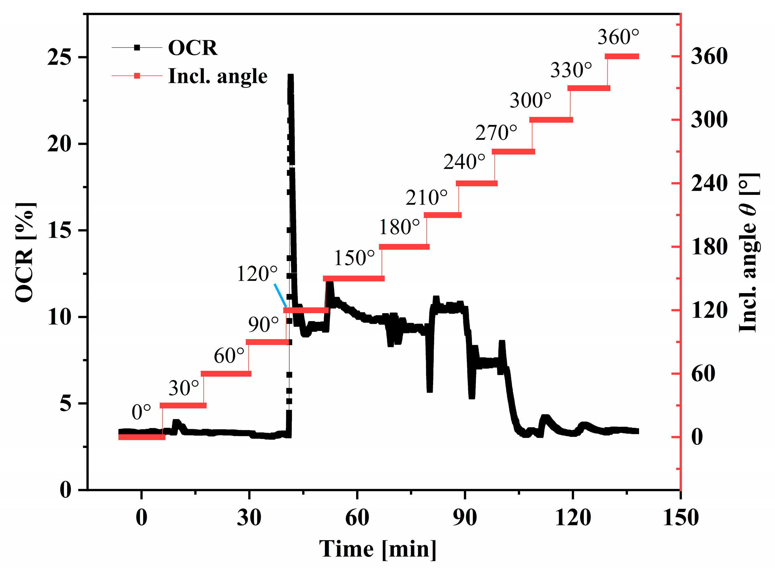
Figure 8 shows the effect of the inclination angle on the oil circulation rate during the first test. The graph is approximately symmetrical concerning 180° and shows a higher oil circulation rate between +90° to +270°. Within the range of 0 to 90°, the oil circulation rate remains constant at around 3.36%, with only minor fluctuations with increasing inclination angle. In this case, the compressor is at the top of the system, and the discharge port is higher than the bottom pool, so its oil-spitting characteristics are basically the same as the direction of normal gravity. At 120°, a sudden and significant increase in the oil circulation rate occurred, rising from 3.17% to 23.88% in 20 s, as shown in
Figure 8. Although the duration was brief, the “spike” caused difficulties in curve fitting and further analysis. Even without this “abnormal” behavior, the oil circulation rate at 120° was much higher than other tilt angles, reaching about 9% after the system stabilized, nearly three times the OCR value in the range of 0 to 90°. A slight increase in the oil circulation rate was observed at inclination angles of 300° and 330°. Each change in inclination angle between 120° to 240° resulted in a small, sharp increase in the oil circulation rate followed by a gradual decline until stabilization. This is possibly due to the compressor’s discharge port being lower than the bottom oil pool, resulting in more oil being discharged with the refrigerant. The oil circulation rate trend between 270° to 360° was similar to that of 0° to 90°, with a decrease to nearly 3.46% at 270°.
During the first test, at the inclination angles of 90° and −90°, the compressor discharge pipe was approximately at the same height as the oil pool, but the oil circulation rate remained low without any significant increasing trend. This can be attributed to the adsorption of the lubricant by the capillary structure inside the compressor, which helps stabilize the oil circulation rate. However, when the inclination angle exceeded 90°, there was a sudden and sharp increase in the oil circulation rate, possibly due to the oil pool being positioned higher than the compressor discharge port, leading to a large amount of lubricant being discharged from the compressor. In subsequent tests, the oil circulation rate followed a trend similar to that shown in
Figure 8, without the 120° spike, and it took some time for the lubricant to return to the compressor.
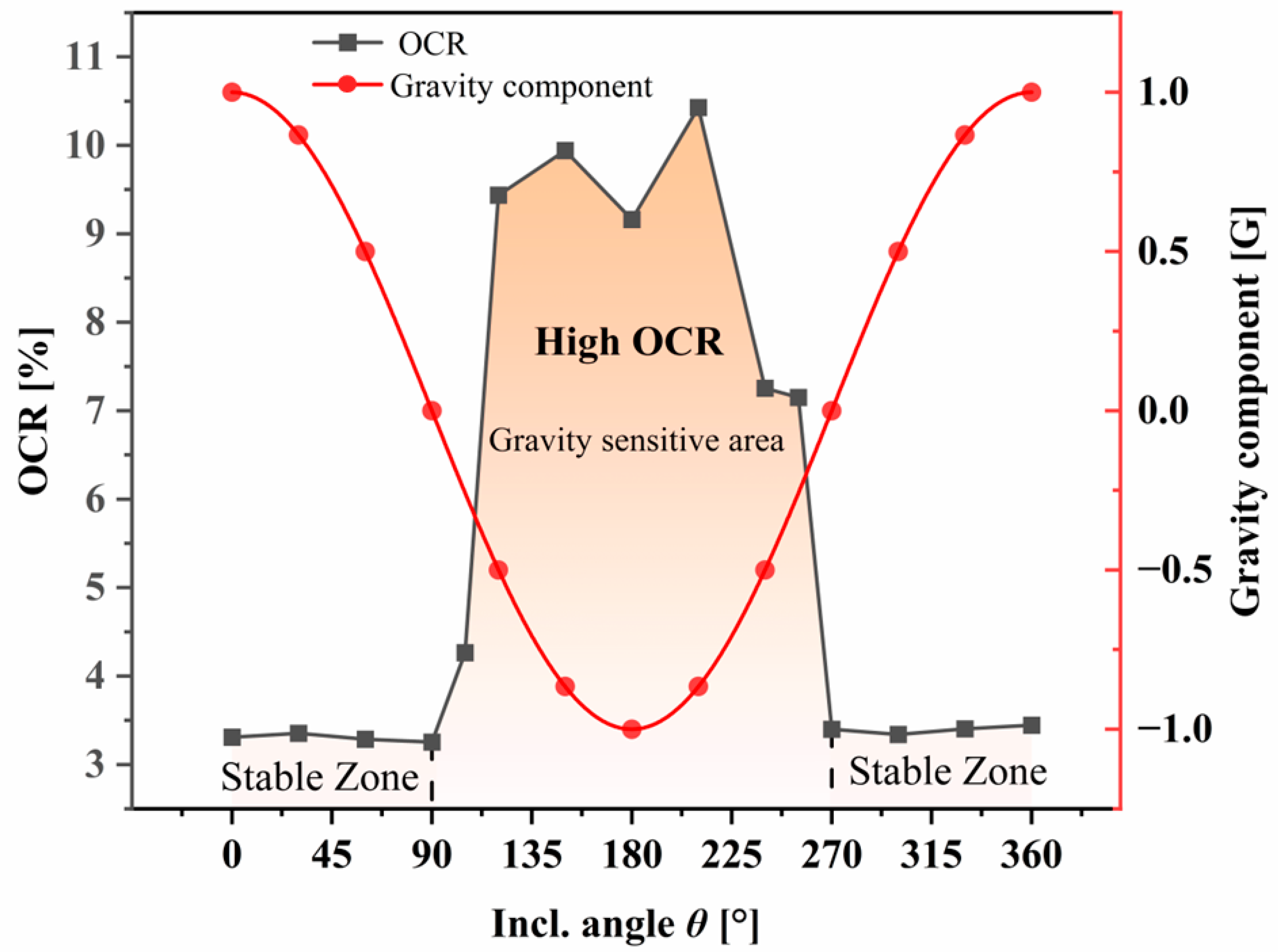
The effect of gravity on the oil circulation rate is illustrated in
Figure 9. The changes in the oil circulation rate adhere to the following patterns:
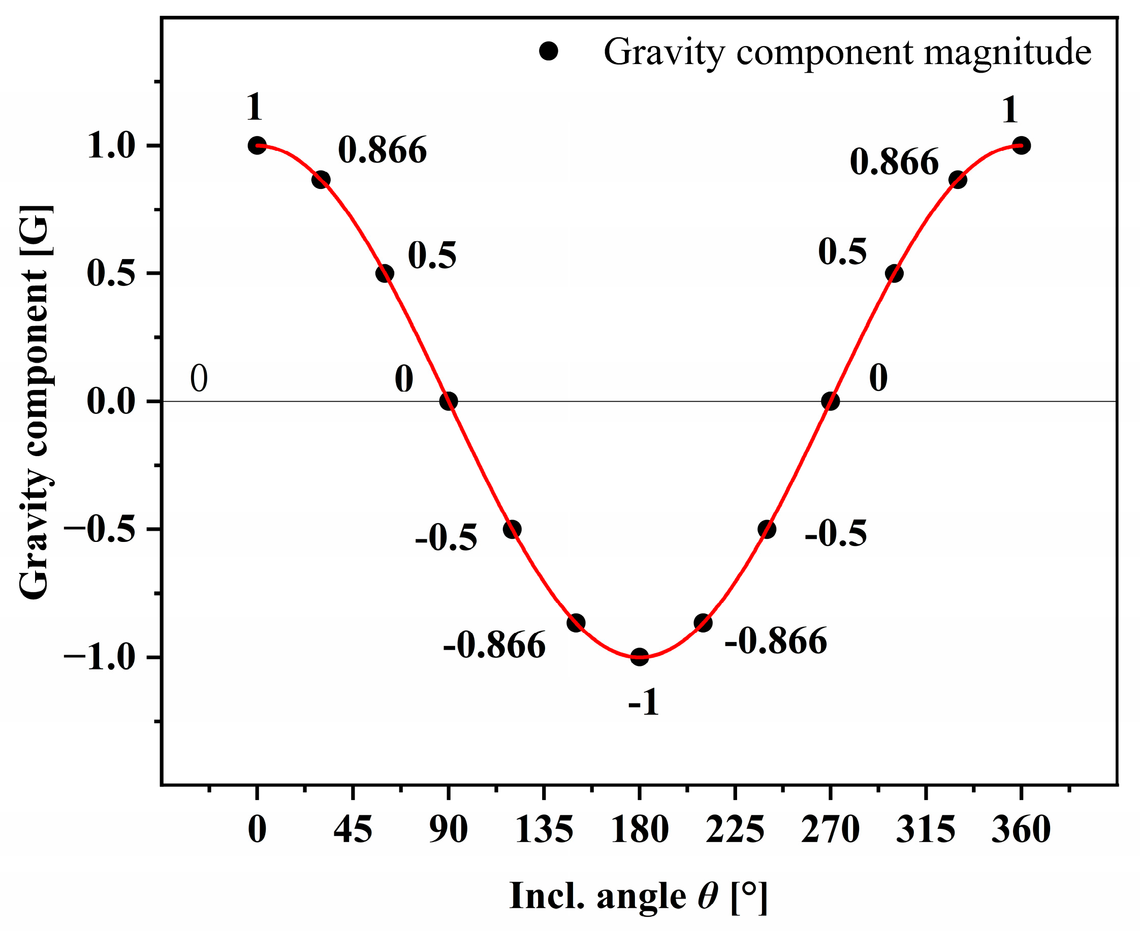
In the inclination angle range of −90° to 90° (0° to 90° and 270° to 360°), the oil circulation rate is minimally influenced by the inclination angle change, and can be segregated into a stable region; the gravity-sensitive area encompasses the range of 90° to 270°, where the oil circulation rate changes rapidly with variations in the angle due to system’s sensitivity to gravity when the gravity component direction is negative;
Any inclination angle change produces oscillations in the oil circulation rate, with greater changes observed when the compressor discharge port is lower than the oil pool. Conversely, when the discharge port is higher than the oil pool, the changes are minimal;
In the range of 90° to 270°, the oil circulation rate is significantly influenced by the inclination angle, and remains at a high level. When the direction of the gravity component is negative, the oil circulation rate increases with the magnitude of the gravity component.
Figure 9.
Schematic diagram of the test stand inclination with gravity component and high oil circulation rate interval.
Figure 9.
Schematic diagram of the test stand inclination with gravity component and high oil circulation rate interval.
The oil circulation rate in the system is affected by the direction of the gravity component. When the gravity component is negative, the oil pool is located on the top of the compressor. As a result, lubricant is discharged more rapidly, and the system’s oil circulation rate is higher. Conversely, when the gravity component is positive, lubricant is mainly transferred to the moving parts via the crankshaft drive, with refrigerant carrying out the oil out of the compressor, leading to a lower oil circulation rate. Within the gravity-sensitive area, an increase in the magnitude of the gravity component causes an increase in the oil circulation rate, as it facilitates lubricant discharged from the compressor. However, at the tilt angle of 180°, where the system is inverted, lubricant is deposited near the discharge port and is completely separated from the crankshaft drive, leading to a decrease in the oil circulation rate. At this point, the compressor relies heavily on the refrigerant work mass for a large-scale operation, resulting in a still-high oil circulation rate.
In order to reduce the fluctuation magnitude of oil circulation rate in system operation and improve the operating efficiency of vapor compression heat pump, capillary structure can be considered for capturing lubricating oil in the compressor. This not only helps to maintain the lubrication inside the compressor, but also restricts the lubricant from spitting out from the compressor in large quantities and making the heat transfer efficiency of the system decrease. In addition, the use of oil separators is a common method. However, in a microgravity environment, the normal gravity-dependent oil separators become ineffective. It is equally possible to use a gas–liquid separator with a capillary structure applied to separate the refrigerant from the lubricating oil, which is pumped back into the compressor under differential pressure. It can be seen that capillary structures are important in the direction of gas–liquid separation in a microgravity environment because they are not gravity-dependent.
3.3. Effect of Gravity on System Temperature Distribution
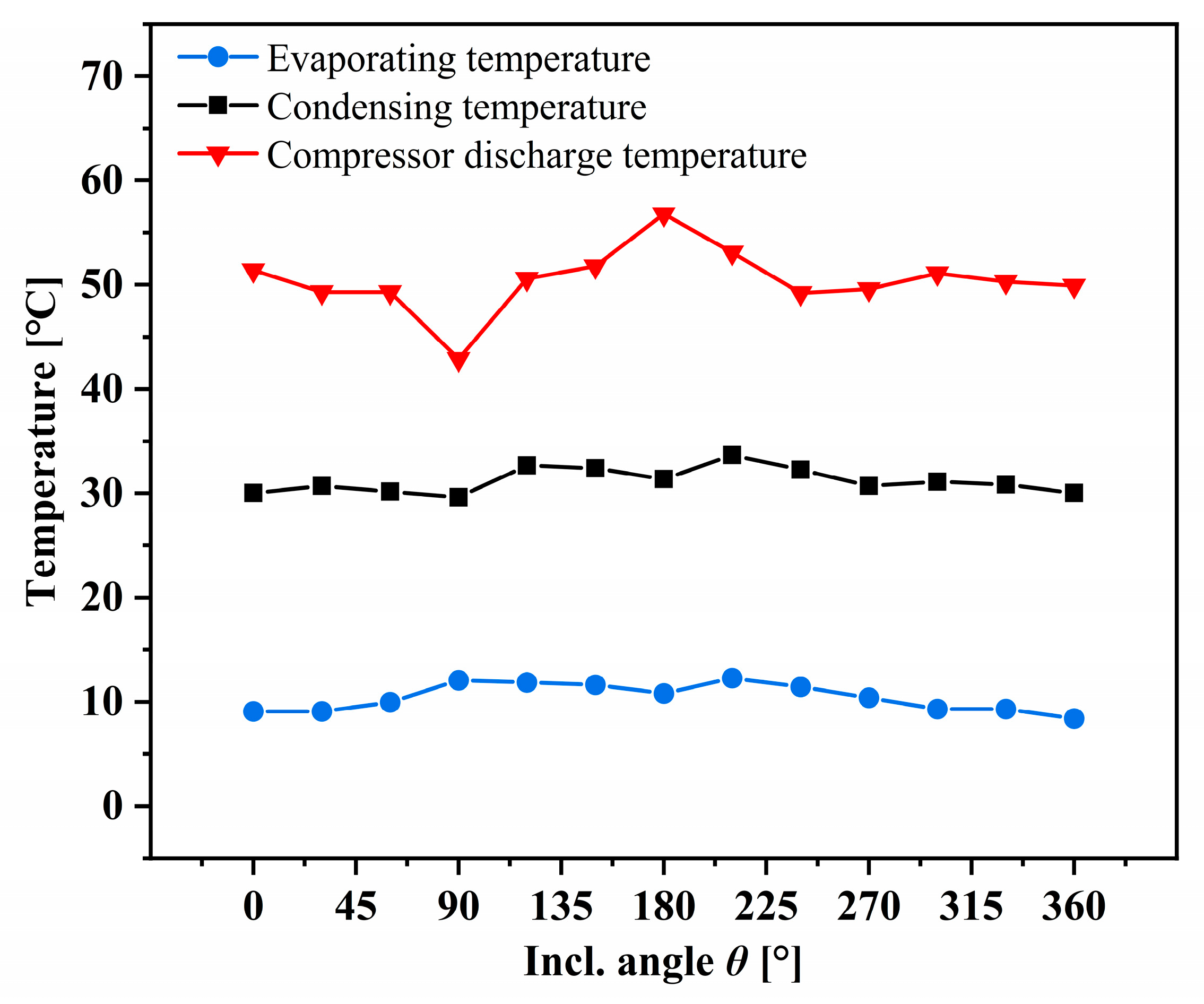
Figure 10 shows the effect of tilt angle on evaporating temperature, condensing temperature, and compressor discharge temperature, and it can be found that evaporating temperature, condensing temperature, and discharge temperature are roughly axisymmetrically distributed with respect to 180°.
The inclination angle was varied from 0° to 360°, resulting in a range of evaporation temperature from 8.4 °C to 12.3 °C. During the range of 0° to 90°, the evaporation temperature increased gradually. It then decreased between 90° to 180°, with a peak value of 12.1 °C occurring at 90°. However, when the platform turned from 180° to 360°, the highest evaporation temperature peak appeared at 210°, gradually decreasing until the completion of the angle variation experiment at 360°. The evaporation temperatures were recorded to be 9.1 °C and 8.4 °C at 0° and 360°, respectively, after rotating one full circle and returning to the initial position. The evaporation temperature decreased by 0.7 °C after rotating the experimental platform back to the initial position.
During the experiment, the condensation temperature ranged between 29.6 °C and 33.7 °C, and its symmetry became more pronounced. In contrast to the trend of the evaporation temperature, the condensation temperature reached a low point of 29.6 °C at an inclination angle of 90°. However, at an inclination angle of 180°, the condensation temperature obtained a relatively low value of 31.4 °C, similar to the trend of the evaporation temperature. The condensation temperature was 30.0 °C at both 0° and 360°, indicating that after a full 360° rotation, the temperature returned to its initial value.
During the experiment, the compressor discharge temperature ranged from 42.9 °C to 56.8 °C. At an inclination angle of 90°, the lowest discharge temperature of 42.9 °C was observed. Conversely, at an inclination angle of 180°, which caused the compressor to be in an inverted state with increased friction in the cylinder, the discharge temperature reached its highest point of 56.8 °C. The discharge temperature exhibited the greatest variation among the evaporation and condensation temperatures, with a range of 13.9 °C.
Taking into account the effect of oil circulation rate on the refrigeration cycle and compressor, in the temperature range of 90 to 270°, the subcooled piping section of the system maintains a relatively high oil circulation rate. This leads to an increase in the lubricating oil discharge of the compressor, which can reduce the heat transfer performance of the heat exchanger, causing an increase in evaporation pressure and condensation pressure. Additionally, the compressor exhibits intermittency and hysteresis in its oil return process, and a high oil circulation rate can result in oil starvation in certain compressor parts, leading to reduced compressor performance. The oil pool at the bottom of the compressor relies on the pressure difference and the drive of the crankshaft to transport lubricating oil to the moving parts. As a result of lubricating oil partially detaching from the oil pool within the range of 90 to 270° inclination angle, high-pressure gas return to the suction line can occur, resulting in reduced compressor suction capacity, increased power consumption, and compressor discharge temperature.
3.4. Effect of Gravity on System Superheat/Subcooling
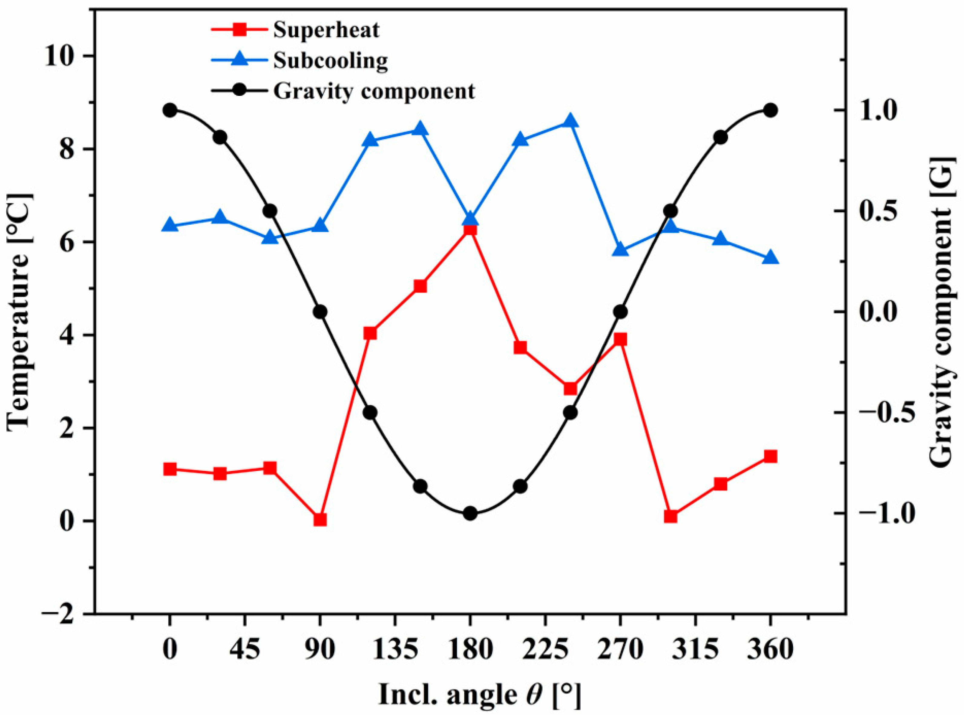
The effects of the inclination angle and gravity component on the superheat and subcooling of the system are presented in
Figure 11. The superheat degree is greater in the range of inclination angle 120~270°, while it is smaller in the range of 0~90° and 300~360°. For inclination angles in the range of 0–90°, the superheat degree initially varies little with increasing inclination angle, but then reduces, reaching a minimum value of 0 °C at 90° when the evaporator outlet is in a gas–liquid two-phase state with no superheat. A similar situation occurs at 300°. This behavior is primarily due to the combined effects of oil circulation rate, refrigerant flow, and evaporation temperature. In the inclination angle range of 0–90°, the low oil circulation rate and decreased refrigerant flow lead to an increase in superheat. However, the increase in evaporation pressure leads to an increase in evaporation temperature, which causes a decrease in superheat. Therefore, the superheat does not change significantly at first under their joint effect. At 90°, the superheat degree is further reduced, and even the refrigerant is still in a two-phase state at the evaporator outlet. For 90° < θ < 270°, the oil circulation rate is higher, and the increased lubricant in the heat exchanger leads to a decrease in heat transfer efficiency, which in turn causes an increase in system superheat. When considering the effect of the gravity component on the system temperature, the degree of superheat increases with the increase in the magnitude of the negative gravity component. When the gravity component is −G, the compressor is in an inverted state, and the system’s superheat is at a maximum.
The subcooling degree is mainly affected by the heat dissipation condition, with its main influencing factors being refrigerant flow and condensing temperature. The subcooling degree varies between 5.8 °C and 8.6 °C when the inclination angle changes from 0 to 360°, with a small change of only 2.8 °C. The subcooling degree does not change significantly in the inclination angle range of 0–90° and 270–360°, whereas in the inclination angle range of 90–270°, the subcooling degree is symmetrical with respect to 180°, with the minimum value appearing at 180° when the compressor is inverted. The change in subcooling degree exhibits high consistency with condensing temperature.
3.5. Effect of Gravity on COP
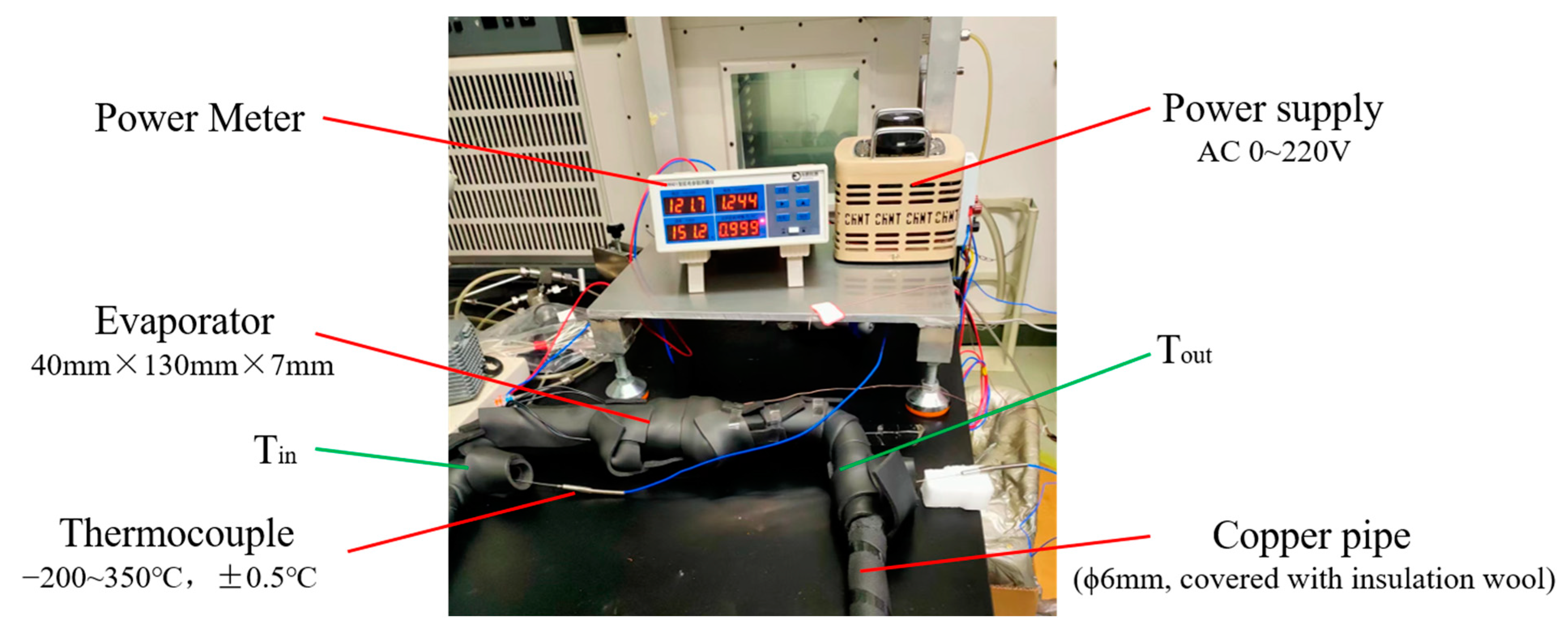
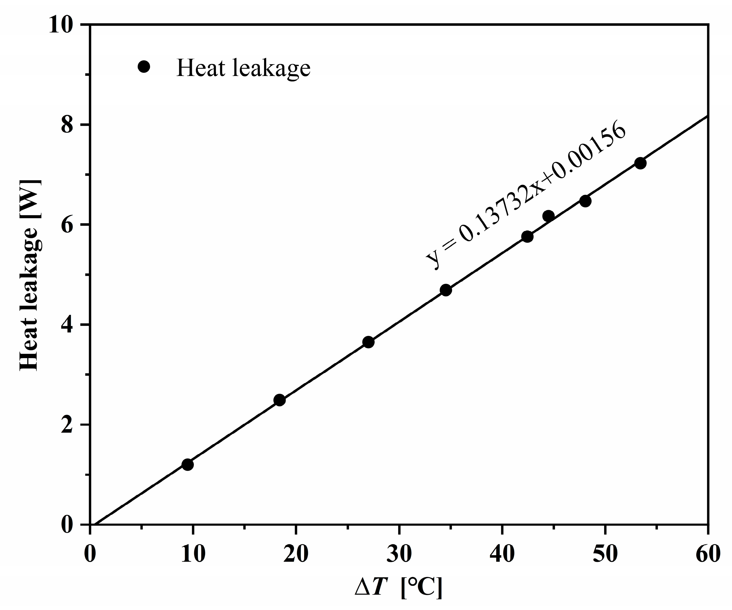
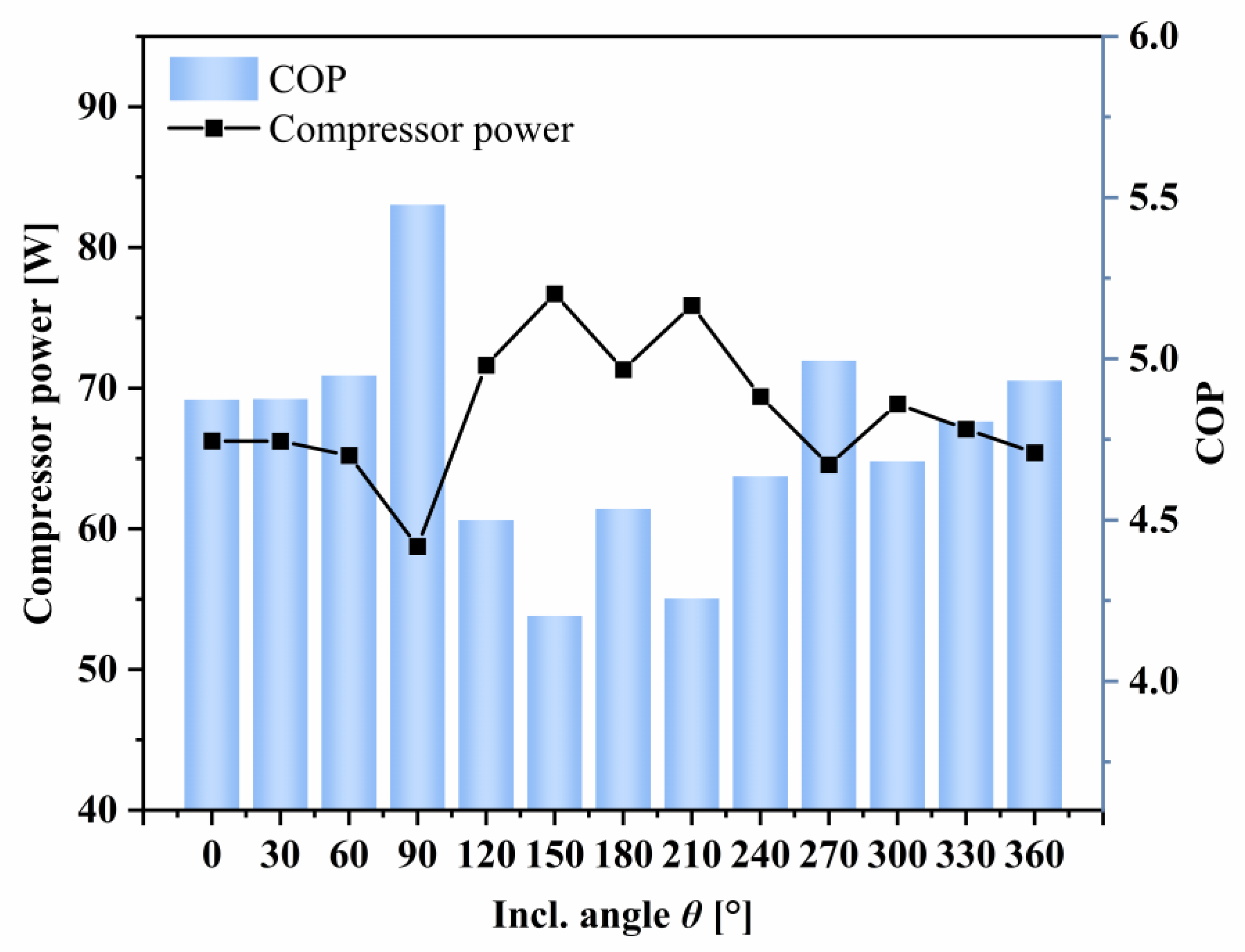
Figure 12 shows the influence of the inclination angle on the power consumption of the compressor and the system COP. During the experiment, the actual refrigeration capacity is equal to the heating power minus the heat leakage. Under the same heating power, due to the small difference in heat leakage of only 1~2 W, there is not much difference in refrigeration capacity. The system COP is mainly affected by the power consumption of the compressor under this condition. The power consumption and COP of the compressor are roughly symmetrically distributed relative to the inclination angle. In the experimental inclination angle of this paper, 180°, which is the upside-down situation, is not the lowest point of the system COP. The minimum value of the system COP is obtained near 150° and 210°. The lowest power consumption of the compressor is obtained at an inclination angle of 90°, where the power consumption is 58.75 W, and the maximum COP of the system is achieved, with a maximum COP of 5.5.
The oil circulation rate will affect the performance and power consumption of the compressor, further affecting the system COP. Within the range of inclination angle of 120~240°, the oil circulation rate is relatively high, the lubricating oil discharge of the compressor increases, and the intermittency and lagging of the oil return process cause the lubricating oil inside the compressor to decrease, the exhaust temperature to increase, and the performance of the compressor to decline. At the same time, the position of the bottom oil pool is higher than the compressor exhaust port, and the separation of the lubricating oil from the oil pool may cause high-pressure gas to flow back to the suction pipeline, resulting in leakage from the high-pressure side to the low-pressure side, which not only increases the evaporation pressure but also increases the power consumption of the compressor and decreases the COP. When the inclination angle is 90°, the oil circulation rate is relatively small, the heat exchanger has good heat exchange performance, and the lubricating oil inside the compressor can meet the needs of lubrication and sealing. The operating state of the compressor is good, and the exhaust temperature and power consumption are low, thereby achieving the maximum COP.
4. Discussion
Changes in the inclination angle of the test stand can cause variations in the gravitational component, which can in turn affect the system’s flow rate, pressure, and oil circulation rate, thereby influencing the overall performance of the system. The experimental results presented in this paper show a sinusoidal variation in the system flow rate, which is similar to the results obtained in the tilt experiments conducted by Brendel et al. [
29], although there is a certain phase difference between the two. This could be attributed to the differences in the installation positions of system components and how the system angle is rotated. However, both experiments reveal that the maximum flow rate occurs when the condenser is located at the highest point and the evaporator at the lowest point, whereas the minimum flow rate occurs when the condenser is situated at the lowest point and the evaporator at the highest point. This observation may be related to the distribution of refrigerant in the heat exchanger and pipeline under different angles, and the sedimentation of refrigerant liquid in the system that can cause changes in flow rate and pressure, leading to changes in the system’s performance. A hypothesis exists for the study of microgravity two-phase flow, where the effect of gravity on the flow is negligible when the system flow is large enough, i.e., a gravity-independent flow type is achieved. In terms of system flow, the variation of system performance at different flow rates can be further investigated to increase the confidence of system operation in microgravity environment.
The type of refrigerant and lubricant, the initial oil charge ratio, compressor speed, evaporation temperature, and piping geometry characteristics all affect the oil circulation rate of the system. In addition, the type of gas–liquid separator and oil separation efficiency have an important impact on the system oil circulation rate and oil return characteristics. Furthermore, changes in gravity can also affect the oil circulation rate and system oil return, leading to an impact on the compressor’s performance and system heat exchange. When the inclination angle causes the compressor oil pool to be positioned higher than the compressor discharge port, it results in a significant increase in the oil circulation rate, which can be up to three times higher compared to the condition of an upright compressor. This situation can lead to fluctuations in both compressor performance and system heat transfer, thereby affecting system efficiency and stability. Excessive oil can result in a decrease in COP and fluctuations in temperature control characteristics, which can negatively impact the thermal control system. Furthermore, if an excessive amount of lubricating oil exits the compressor, it can result in insufficient lubrication and sealing, leading to a deterioration in compressor performance. Ma et al. [
25] developed a model to study the mixed flow and heat transfer of refrigerant and lubricating oil in the steam compression heat pump evaporator. Ye et al. [
26] conducted simulations to investigate the two-phase flow characteristics of refrigerant-lubricating oil mixture in the compressor under different gravity and lubricating oil volume fractions and verified the model using the experimental values of compressor exhaust temperature. However, there is still limited research on the effect of gravity on the oil circulation rate and oil return characteristics in steam compression heat pump systems. The work in this paper fails to further consider the effects of variations in refrigerant, system flow rate, and heating power under changes in tilt angle, and the compressor is also limited to rotating in one plane, which can be tested by improving the test stand in subsequent experiments. Therefore, further research is necessary to examine the impact of oil circulation rate on system heat transfer, pressure drop, and flow pattern, as well as the compressor’s oil return characteristics under microgravity conditions. Future research opportunities could involve simulating the system and validating the simulation results using the test bed, enhancing the system’s visualization device, and using a high-speed camera to capture the flow of refrigerant and lubricating oil in the system to examine the distribution of refrigerant-lubricating oil mixtures and oil return characteristics.
