Article

Numerical Research on the Jet Mixing Mechanism of the De-Swirling Lobed Mixer Integrated with OGV

1
Key Laboratory of Light-Duty Gas Turbine, Institute of Engineering Thermophysics, Chinese Academy of Sciences, Beijing 100190, China
2
School of Aeronautics and Astronautics, University of Chinese Academy of Sciences, Beijing 100049, China
3
Research Center of Fluid Machinery Engineering and Technology, Jiangsu University, Zhenjiang 212013, China
*
Author to whom correspondence should be addressed.
Energies 2023, 16(11), 4394; https://doi.org/10.3390/en16114394
Submission received: 30 April 2023 / Revised: 26 May 2023 / Accepted: 27 May 2023 / Published: 29 May 2023
(This article belongs to the Topic Advanced Engines Technologies)

Abstract

:
The outlet guide vane (OGV) is integrated with the lobed mixer to improve the exhaust system’s performance with a high core inlet swirl. The best location for integrating the OGV is along the central line of the lobe’s trough and near the exit plane of the lobed mixer. Two types of lobed mixers (the scalloped reference lobed mixer and the scalloped de-swirling lobed mixer) integrating with/without OGVs, are numerically researched under eight inlet swirl conditions ranging from 0° to 35°. The simulation used the Reynolds-Averaged Navier-Stokes (RANS) method with Shear Stress Transport (SST) model based on an unstructured mesh of 30 million cells. The reserved outlet flow angle of the de-swirling lobed mixer is beneficial for enhancing the strength of downstream streamwise vortices and accelerating the jet mixing. After integrating with OGV: it can significantly suppress the leakage vortex between the lobe trough and the central body and the backflow downstream of the central body; on the other hand, it can further increase the strength and scale of streamwise vortices by expanding the radial range of inner secondary flow, thereby accelerating mixing and reducing total pressure loss & thrust loss. Under the design condition, the integrated de-swirling lobed mixer can increase thrust by 3.18% and reduce the mixing loss by 31.17% compared with the reference lobed mixer. Even under non-design conditions, the integrated de-swirling lobed mixer can still use upstream inlet swirl to enhance the streamwise vortices and accelerate the jet mixing within the conditions studied in this paper. The outlet jet uniformity of the integrated de-swirling lobed mixer is better than that of the integrated reference lobed mixer for the case with the same core inlet swirl. Compared with the latter, the former also has better tolerance to the attack angle, especially for the negative attack angle conditions. Under the condition with a core inlet swirl of 35°, the thrust loss of the integrated de-swirling lobed mixer is 2.15% lower than that of the integrated reference lobed mixer.

1. Introduction

The lobed mixer is a forced mixing method successfully applied to turbofan engines with low and intermediate bypass ratios. It offers several advantages, including increased net thrust & mixing efficiency and decreased infrared signature & jet noise. In the 1980s, Povinelli [1], Blackmore [2], and Paterson [3] demonstrated the existence of large-scale vortices downstream of the lobed mixer and their contribution to jet mixing through experimental and numerical methods. The twisted surface of the lobed mixer generates radial upward and downward secondary flows in the core and bypass flow, resulting in large-scale streamwise vortices. Eckerle [4] and Werle [5] noted that these large-scale streamwise vortices accelerate convection between the core and bypass flow, while turbulent spots caused by the breakup of streamwise vortices significantly enhance the mixing process. Manning [6] observed the azimuthal vortices using visualization techniques, while McCormick [7] and Ukeiley [8,9] found that the interaction between azimuthal and streamwise vortices accelerated the formation of turbulent spots and facilitated energy transfer between the core and bypass flow. Belovich et al. [10] identified three reasons why the lobed mixer promotes jet mixing: (1) an increased contact area between core and bypass flow due to its twisted surface; (2) the streamwise vortices induced by radial secondary flows; and (3) the azimuthal vortices caused by Kelvin-Helmholtz instability.
Studies of the jet mixing mechanism of lobed mixers are typically conducted under conditions without inlet swirl, which does not reflect the actual state of turbine systems. Research [11,12,13,14,15,16,17] found that inlet swirl is generally detrimental and can cause significant losses. Although the lobed mixer eliminates most of the swirling flow, a considerable amount of swirling flow remains around the central body. As a result, they suggested that turbine systems should be carefully designed to eliminate swirling flow at the outlet of low-pressure turbines (LPT). The authors’ team conducted a series of studies [18,19,20,21,22,23,24,25] to understand the flow mechanism in lobed mixers under inlet swirl conditions. They found that the inlet swirl could introduce an additional streamwise vortex that improved the jet mixing. However, the higher inlet swirl (greater than 20°) resulted in significant thrust loss (12.7% at 30°). To eliminate and use leakage swirling flow, the authors’ team [23,24] designed and evaluated a new de-swirling lobed mixer numerically and experimentally. The de-swirling lobed mixer rearranged the loading distribution on the suction side. It significantly decreased total pressure loss and thrust loss compared to the reference lobed mixer under the high inlet swirl conditions. However, the new de-swirling lobed mixer could not reduce leakage swirl between the lobe trough and central body. As a result, a new structure of lobed mixer integrated with LPT Outlet Guide Vanes (OGVs) was used to eliminate leakage swirl and reduce exhaust system length/weight simultaneously. This paper studied the reference and de-swirling lobed mixers integrated with/without OGVs under eight inlet swirl conditions ranging from 0° to 35°.

2. Numerical Method

Two types of lobed mixers (the scalloped reference lobed mixer and the scalloped de-swirling lobed mixer) integrating with/without OGVs, are numerically researched under eight inlet swirl conditions ranging from 0° to 35°. The commercial ANSYS CFX solver simulation solves the three-dimensional RANS equations with the SST model [26]. The high-order and second-order backward Euler difference methods are used for the convection and time terms, respectively, and all residual convergence values are set as 10−6.

2.1. Model of Lobed Mixer

Figure 1 shows the models of the scalloped reference lobed mixer integrated with OGVs (IRLM) and the scalloped de-swirling lobed mixer integrated with OGVs (IDLM). Both models include a lobed mixer, integrated outlet guide vanes (IOGVs), and a central body. The main parameters of the reference lobed mixer are shown in Figure 2. This mixer has 15 lobes, with a lobe length of 94 mm, a lobe height of 47 mm, a rise angle of 20°, and a fall angle of 25°.
Based on the geometry of the reference lobed mixer and blade design methods, the authors’ team designed a new de-swirling lobed mixer for high inlet swirl conditions. The design process for the de-swirling lobed mixer was as follows: several radial sections and the camber curve of the reference lobed mixer were extracted, as shown by the red and blue dashed lines in Figure 2; the camber was then transformed into a parabola by specifying the inlet and outlet metal angles of the de-swirling lobed mixer; the contour profiles of the radial sections were then redesigned based on the principle of thickness invariance; finally, the de-swirling lobed mixer was constructed by stacking radial sections along the new chamber line. The detailed design procedure can be found in Ref. [24]. For the de-swirling lobed mixer, its inlet and outlet metal angles are 20° and 5°, respectively. The reserved 5° metal angle at the outlet is beneficial for enhancing streamwise vortices downstream of the lobed mixer. Figure 3 shows the parameters of the scalloping notch for both the scalloped reference lobed mixer (RLM) and the scalloped de-swirling lobed mixer (DLM). The height of the scalloping notch is 28.7 mm at the trailing edge of the lobed mixer, with a fillet radius of 11.6 mm. The angles of the upper and lower edges are 0° and 22°, respectively.
Based on the geometry of the reference lobed mixer and blade design methods, the authors’ team designed a new de-swirling lobed mixer for high inlet swirl conditions. The design process for the de-swirling lobed mixer was as follows: several radial sections and the camber curve of the reference lobed mixer were extracted, as shown by the red and blue dashed lines in Figure 2; the camber was then transformed into a parabola by specifying the inlet and outlet metal angles of the de-swirling lobed mixer; the contour profiles of the radial sections were then redesigned based on the principle of thickness invariance; finally, the de-swirling lobed mixer was constructed by stacking radial sections along the new chamber line. The detailed design procedure can be found in [24]. For the de-swirling lobed mixer, its inlet metal angle and outlet metal angle are 20° and 5°, respectively. The reserved 5° metal angle at the outlet is beneficial for enhancing streamwise vortices downstream of the lobed mixer. Figure 3 shows the parameters of the scalloping notch for both the scalloped reference lobed mixer (RLM) and the scalloped de-swirling lobed mixer (DLM). The height of the scalloping notch is 28.7 mm at the trailing edge of the lobed mixer, with a fillet radius of 11.6 mm. The angles of the upper and lower edges are 0° and 22°, respectively.
Figure 4 shows the profile of OGVs integrated with a lobed mixer. The inlet flow angle and outlet flow angle are 20.3° and 3°, respectively. The chord length is 20.0 mm, and the maximum thickness is 1.87 mm. The OGV is designed as a straight blade connecting the lobe trough and central body, resulting in 15 OGVs in the entire circle. Figure 5 shows the thrust coefficient and total pressure loss of IRLM for different IOGV integration schemes in cases with a core inlet swirl of 20°. The abscissa represents the distance between the trailing edge of IOGV and the outlet of the lobed mixer. As the axial distance increases, the thrust coefficient first decreases and stabilizes at around 0.995, while total pressure loss first increases and then decreases. Therefore, it is better to integrate the OGV at the lobed exit (the axial location of OGV = 0) for higher thrust and lower total pressure loss.

2.2. CFD Domain and Mesh

Figure 6 shows the computational domain of the lobed mixer, which is a 24° sector between the two red crest lines in Figure 1. This domain includes the lobed mixer, central body, and mixing nozzle. In addition, a far field was established downstream of the mixing nozzle with a radial extent of 5 Dh (where Dh is the hydraulic diameter of the core flow at the lobe exit) and an axial extent of 20 Dh to simulate jet mixing with ambient air.
The boundary settings of the computational domain are shown in Figure 6, with corresponding boundary conditions shown in Table 1. The bypass and core inlet are velocity inlets, with their axial velocities set to 40 m/s and 30.8 m/s, respectively. The temperature ratio of the bypass flow to the core flow is 1. The tangential flow angle of the core inlet is set according to different inlet swirl cases, such as 0°, 5°, 10°, 15°, 20°, 25°, 30°, and 35°. The two sides of the computational domain are set as periodic boundaries; the inlet of the far-field is set as an opening boundary with a static pressure of 101,325 Pa; the outlet is a pressure outlet with a static pressure of 101,325 Pa; and other solid surfaces are set as no-slip adiabatic walls. As a result, the calculated Reynolds number was 2.2 × 10⁴ based on the hydraulic diameter of the core outlet and the core axial velocity in all cases, which was greater than the critical value defined by Manning [6].
The computational domain is meshed using ANSYS ICEM with an unstructured tetrahedral grid. For convenience in mesh refinement, the computational domain is divided into two sub-domains (as shown in Figure 6): the lobe exhausting system domain and the far field. The meshes in the boundary layers are refined with 15 layers of prism grid: the height of the first layer is set to 0.03, the expansion ratio is 1.15, and y+ is smaller than 1.0. The total number of cells is confirmed as 30 million through grid independence tests: the lobe exhausting system (Figure 7) and far-field cell numbers are 16 million and 14 million, respectively.
Calculations are performed using the ANSYS CFX Solver. To close the Reynolds-averaged Navier-Stokes equations, our team tested SST, k-ε, and k-ω models on the reference lobed mixer integrated with OGV with the same mesh in a case with an inlet swirl of 20°. The results (Figure 8a,b) showed that the SST model had the best accuracy in agreement with experimental results. Therefore, the SST model was also chosen to close the Reynolds-averaged Navier-Stokes equations in this paper. The calculations were performed on a server with 64 processors, each taking 10 h to converge.

2.3. Verification

Experiments on the reference lobed mixer integrated with OGV (IRLM) were conducted on the large-scale co-axial tunnel of the Institute of Engineering Thermophysics, C.A.S., to verify the accuracy of the CFD method. A comparison between experimental and numerical results is shown in Figure 8 for a case with an inlet swirl of 20°, where the grid used for calculation is the one evaluated for grid dependency in the previous section. As shown in Figure 8a, the calculated tangential flow angle agrees well with the experimental one in the range of 0.7 Dh to 1.2 Dh, while it is slightly larger than the latter in the range of 0.44 Dh to 0.7 Dh. The simulated total pressure coefficients (Figure 8b) are consistent with the experimental results throughout the radial range, except for the two peak regions. As shown in Figure 8c, the simulated location and shape of the azimuthal vortices have good consistency with experimental results, but the calculated azimuthal vorticity is higher than the experimental one. These differences may be due to errors in the seven-hole probe, which identifies the velocity gradient as the flow angle in high-velocity gradient regions (such as high shear layers) [21]. Overall, CFD simulation can accurately capture the parameter distributions and vortex structures downstream of IRLM.

2.4. Data Reduction

The performance of the exhausting system was evaluated using relative thrust (Tre), total pressure loss (Y), and their relative changes compared to the baseline case. The relative thrust (Tre) and total pressure loss (Y) were defined as follows:
T re = T / ( 0.5 ρ u ¯ c o r e , i n 2 D h 2 )
where T = e x i t u d m ˙ + e x i t ( P s , e x i t P s , a t m ) d A
Y = i n C p 0 d m ˙ i n d m ˙ e x i t C p 0 d m ˙ e x i t d m ˙
where C p 0 = P 0 P ¯ s , i n P ¯ 0 , i n P ¯ s , i n
The real thrust T includes momentum thrust and static pressure thrust at the nozzle exit, and the non-dimensional thrust CT is calculated by dividing T by 0.5 ρ u ¯ c o r e , i n 2 D h 2 . The non-dimensional total pressure coefficient Cp0 is calculated using the total pressure at the measuring point and the mass-averaged static & total pressure in the inlet of the exhaust system, including the core inlet and bypass inlet. The total pressure loss is the difference between the mass-averaged value of Cp0 at the nozzle inlet and nozzle exit.
To analyze the mixing state at the axial section downstream of the lobed mixer, a non-dimensional parameter, called the mixing coefficient Ig, is used to evaluate the dispersion degree of the flow parameter. It is defined as follows:
I g = s ρ u x ( g g ¯ g ¯ ) 2 d A s ρ u x d A
The variable ‘g’ can represent any parameter of the flow field, such as total pressure or velocity. For an evenly distributed flow field, the mixing coefficient Ig is supported to be 0. This paper chooses the total pressure as the parameter ‘g’ to calculate the mixing coefficient. A lower value of Ip0 indicates the core and bypass flows are mixing more effectively.
The streamwise vorticity (ωs) and azimuthal vorticity (ωa) are used to analyse the development of the vortex system. The definition of ωs and ωa is derived from the partial derivative of velocity under the Cartesian coordinate system:
ω s = ( w y v z )
ω a = ( u z w x ) 2 + ( u y v x ) 2
where u, v, w represent the velocity components in the x, y, and z directions. Cws and Cwa are dimensionless vorticity parameters calculated by dividing ωs and ωa by ucore,in/Dh, respectively.

3. Results and Discussion

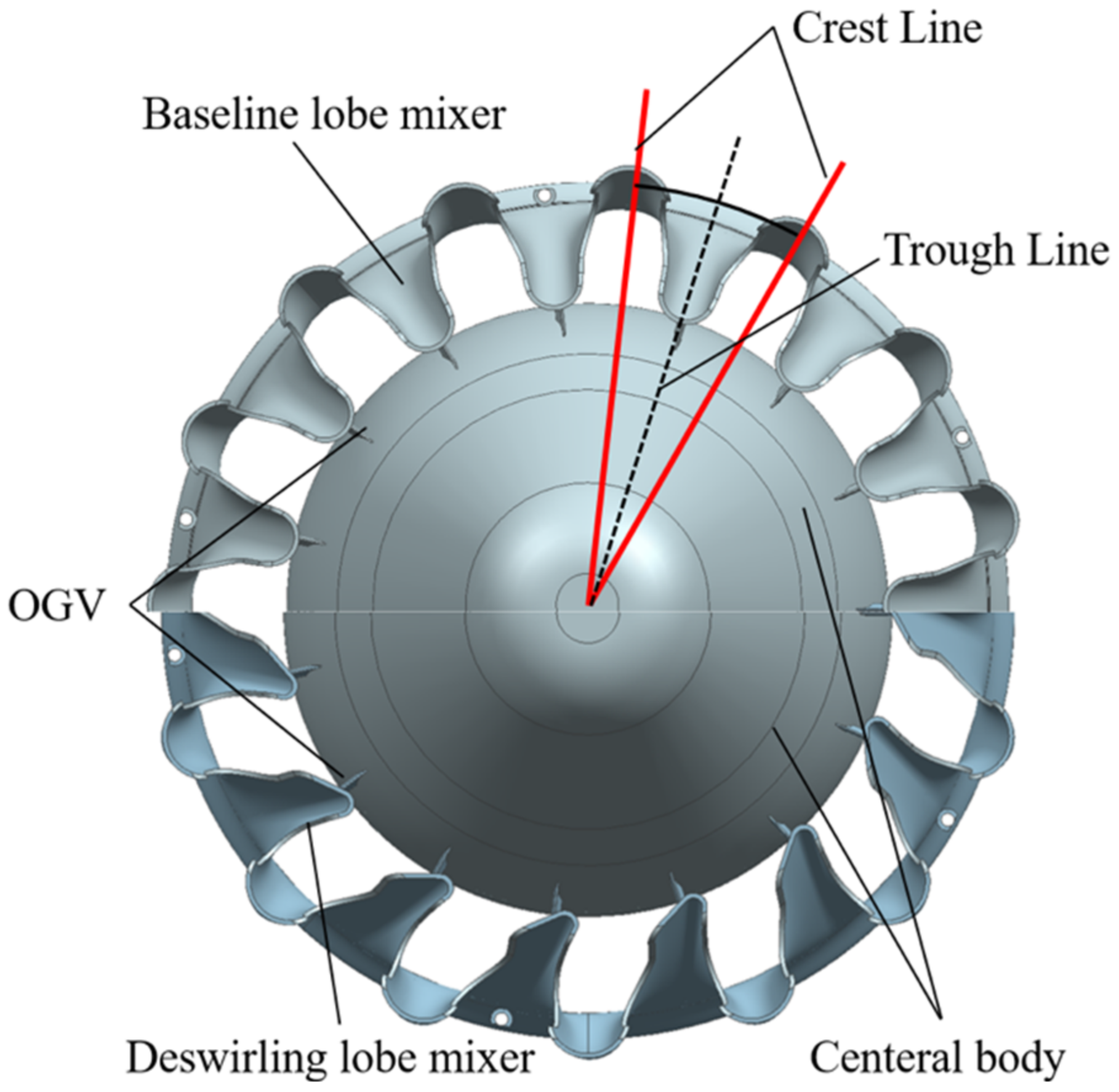
This paper studies four different geometric models of the lobed mixer, including two types of lobed mixers and an integrated OGV. The de-swirling mechanism of the integrated OGVs is first examined under design conditions. Then, the off-design cases with inlet swirls ranging from 0° to 35° are analyzed to estimate the influence of the integrated OGVs on the aerodynamic performance of the lobed mixer.

3.1. Mixing Mechanism of IDLM on Design Condition

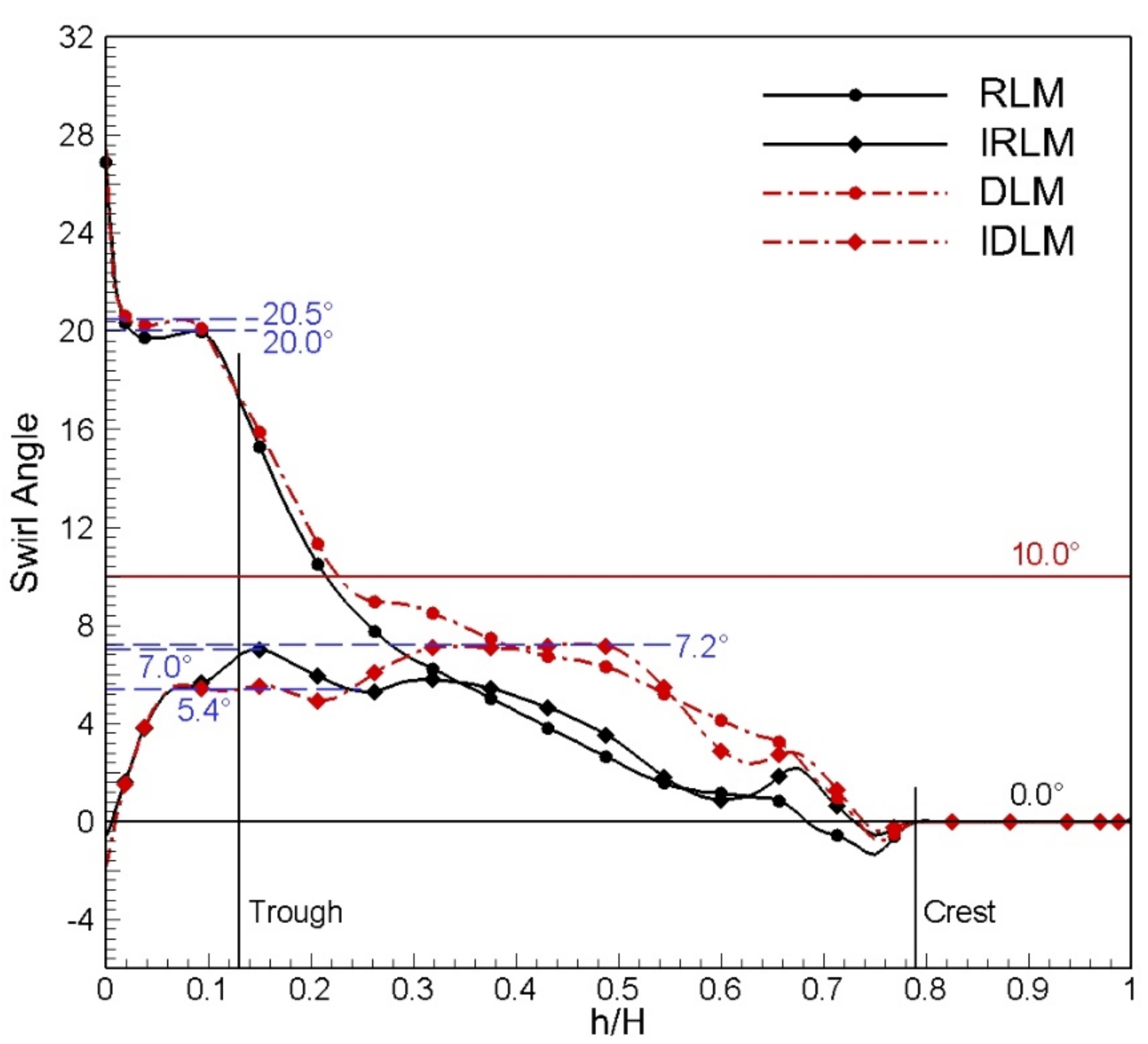
Figure 9 shows the radial distribution of the pitch-wise mass-averaged flow angle at the outlet of the lobed mixer (x = 0.4 Ln) for cases with a core inlet swirl of 20°. The positions corresponding to the trough and crest of the lobed mixer are marked. The abscissa represents the dimensionless height, and H is the channel height of this section. Between the trough and the central body (0 < h/H < 0.13), there is a strong leakage swirling flow for both the scalloped reference lobed mixer (RLM) and the scalloped de-swirling lobed mixer (DLM). Their flow angles are 20° and 20.5°, respectively, roughly equivalent to the core inlet flow angle. The leakage swirling flow of DLM is slightly higher than that of RLM, which may be due to the enhancement of leakage swirling flow caused by the raised ridge line of the DLM trough. Under the acceleration effect of the tapered central body, this strong leakage swirling flow can reach a flow angle of more than 50° when it reaches the exhaust system outlet section, causing a backflow in the center of the jet and increasing total pressure loss and thrust loss of the exhaust system. After integrating with the low-pressure turbine outlet guide vane, this part of the leakage swirling flow is well suppressed: the flow angle in this region downstream of IRLM is less than 7° and remains at around 5.4° for IDLM. Even under the acceleration effect of the tapered central body, the tangential flow angle at the outlet is still less than 20°, effectively suppressing backflow in the center of jet flow and reducing thrust loss and total pressure loss of the exhaust system. As only a small part of the lobed mixer around the trough de-swirls core inlet swirl, there is a high residual swirling flow in region 0.13 < h/H < 0.24 downstream of RLM and DLM, with its flow angle decreasing sharply as h increases. This high residual swirling flow can cause flow separation around the lobe’s trough, resulting in increased thrust and total pressure loss [21,23]. After integrating with OGV, the residual tangential flow angle in the corresponding region downstream of IRLM is less than 7° and is further reduced to about 5.4° for IDLM. This shows that integrating OGV significantly improves the de-swirl ability in this region and that IDLM has a better de-swirl effect than IRLM. In the region of 0.24 < h/H < 0.79, as the inner swirling flow goes deeper into the lobed mixer, the de-swirl ability of the lobed mixer increases with h, causing the residual swirl angle in this area downstream of the lobed mixer to continue decreasing as h increases. This residual swirl angle at the same height position downstream of DLM is greater than that of RLM. The average residual swirl angle of DLM is 6.5°, and RLM’s is 3.8°. A higher swirl angle is maintained downstream of DLM to enhance streamwise vortices and accelerate jet mixing in this area. After integrating with the low-pressure turbine outlet guide vane, although the residual swirl angle downstream of IRLM at the same height position has slightly increased, its distribution trend is roughly consistent with that of RLM. The distribution trend of the residual swirl angle downstream of IDLM is also approximately the same as that of DLM: it first remains at around 7.2° and then quickly drops to 0°. It can be seen that the residual swirl angle downstream of DLM and IDLM is greater than that of RLM and IRLM but not greater than 10°. According to the authors’ early research conclusions, when there is a weak swirling flow (<10°) remaining downstream of the lobed mixer, it not only does not increase thrust loss but also helps to enhance streamwise vortices and accelerate jet mixing. In other words, compared with RLM, DLM has better mixing performance, especially IDLM, which will be discussed in detail below.
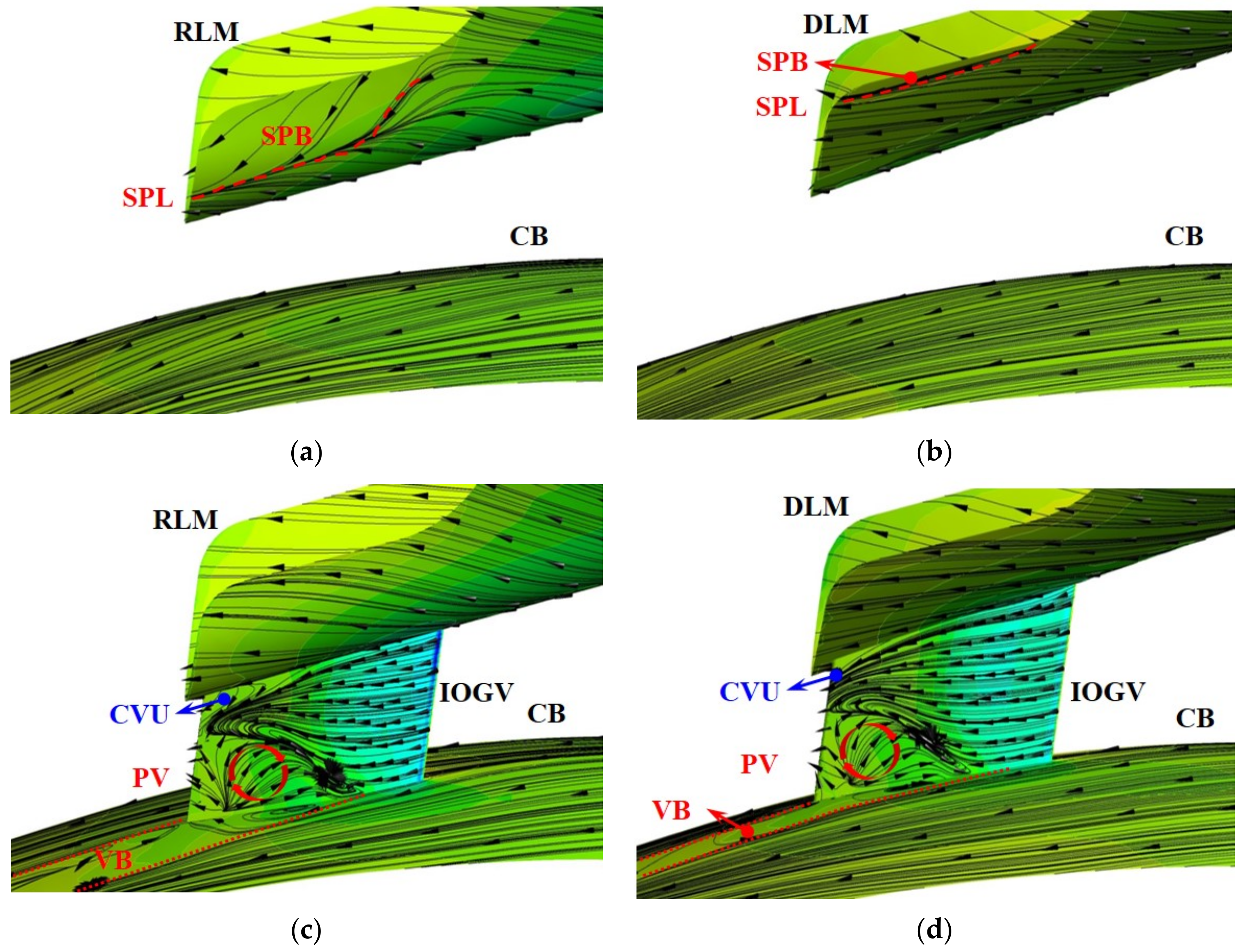
Figure 10 shows the limiting streamlines on the IOGV, central body, and inner surface of different lobed mixers for cases with an inlet swirl of 20°. Before integrating OGV, there are separation bubbles (marked as SPB in the figure) on the inner surface near the trough of RLM and DLM. Compared to the separation line (marked by the red dashed line ‘SPL’ in Figure 10) on RLM, the separation position on DLM is more delayed, and its separation bubble is much smaller than that on RLM, which will be beneficial in reducing separation loss. In the radial interval corresponding to the separation bubble, the mass-averaged inlet swirl angle upstream of RLM and DLM is 15.8° and 16.7°, respectively. This means that DLM can significantly suppress flow separation on the inner surface of the lobed mixer even with a larger inlet swirl angle, showing that the de-swirling lobe design concept greatly enhances the tolerance of the lobed mixer to inlet swirl. After integrating with OGV, there is no flow separation on IRLM and IDLM, indicating that IOGV is beneficial in enhancing de-swirl ability around the lobe’s trough.
On the other hand, although no flow separation is seen on the suction surface of IOGV in IRLM and IDLM cases, an apparent passage vortex (marked as PV in Figure 10) and corner vortex (marked as CVU in Figure 10) appear respectively in the root region and tip area near the trailing edge of OGV. In comparison to the DLM case, the PV in the IRLM case appears at a more upstream position and has a larger radial height when it reaches the trailing edge of IOGV. When the PV detaches from the trailing edge of IOGV, it forms a wider vortex band on the central body, as shown by the VB bounded with the red dotted line in Figure 10. This indicates that the PV on IOGV in the IRLM case has a larger circumferential scale than that in the IDLM case. The passage vortex is mainly influenced by the loading and radial secondary flow of the airfoil. Under conditions with the same loading of IOGV, the PV in the IRLM case is greater than that in the IDLM case, indicating that IRLM has a stronger radial secondary flow. Although a stronger PV will increase loss, it can also enhance streamwise vortices and accelerate jet mixing to a certain extent. The development trend of CVU at the tip region of IOGV is almost identical for both the IRLM and IDLM cases.
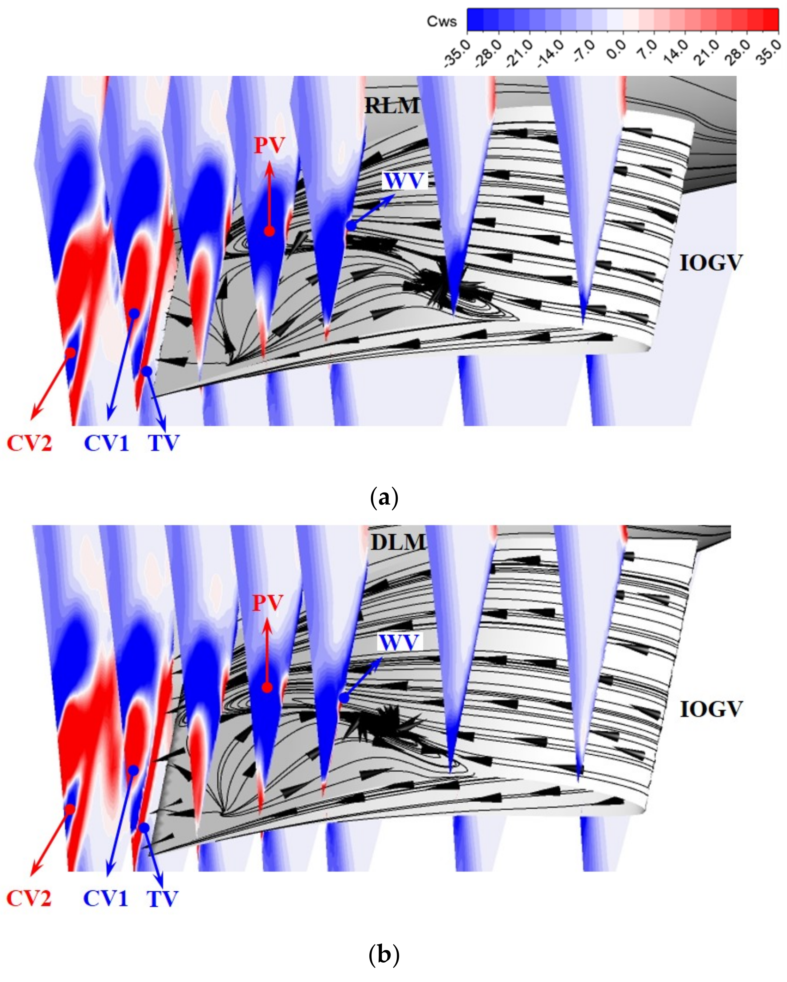
To further compare the vortex structure at the root of IOGV for different integrated lobed mixers, Figure 11 displays the streamwise vorticity contour at various axial sections in the IOGV channel. In both conditions, there is a passage vortex (PV), wall vortex (WV), corner vortex (CV1 and CV2), and trailing edge shedding vortex (TV) in the IOGV passage. PV has the largest scale and strength, followed by CV1 and TV. At the same axial section, the scale and strength of PV and CV1 in the IRLM case are greater than those in the IDLM case, which is consistent with the previous conclusion on PV in Figure 10. The scale and strength of TV on the same section in both cases are roughly equivalent, primarily because TV is mainly affected by the radius of the IOGV trailing edge. Compared to the RLM and DLM conditions, the strong vortex structure appearing at the root of IOGV will significantly enhance jet mixing between the central body and lobe trough. The IRLM case has the strongest vortex structure at the root of IOGV among the four cases, with a core inlet swirl of 20°, indicating that its jet mixing in this area is most intense.
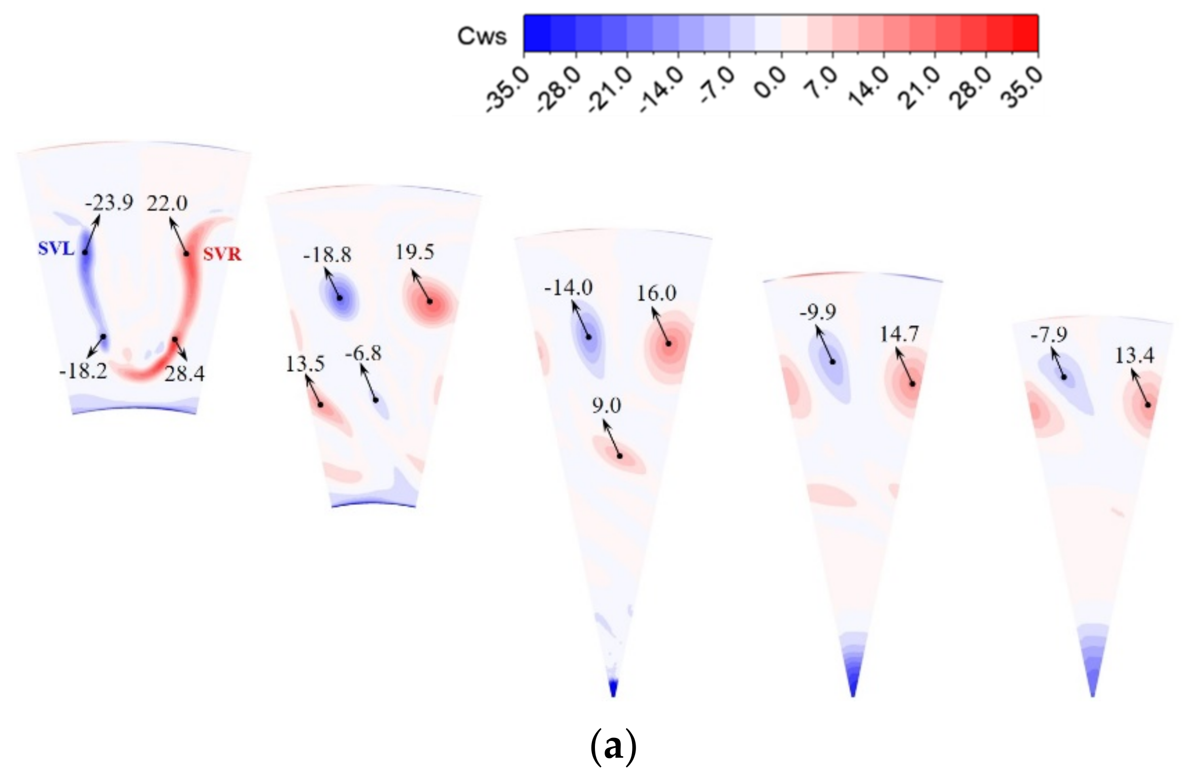
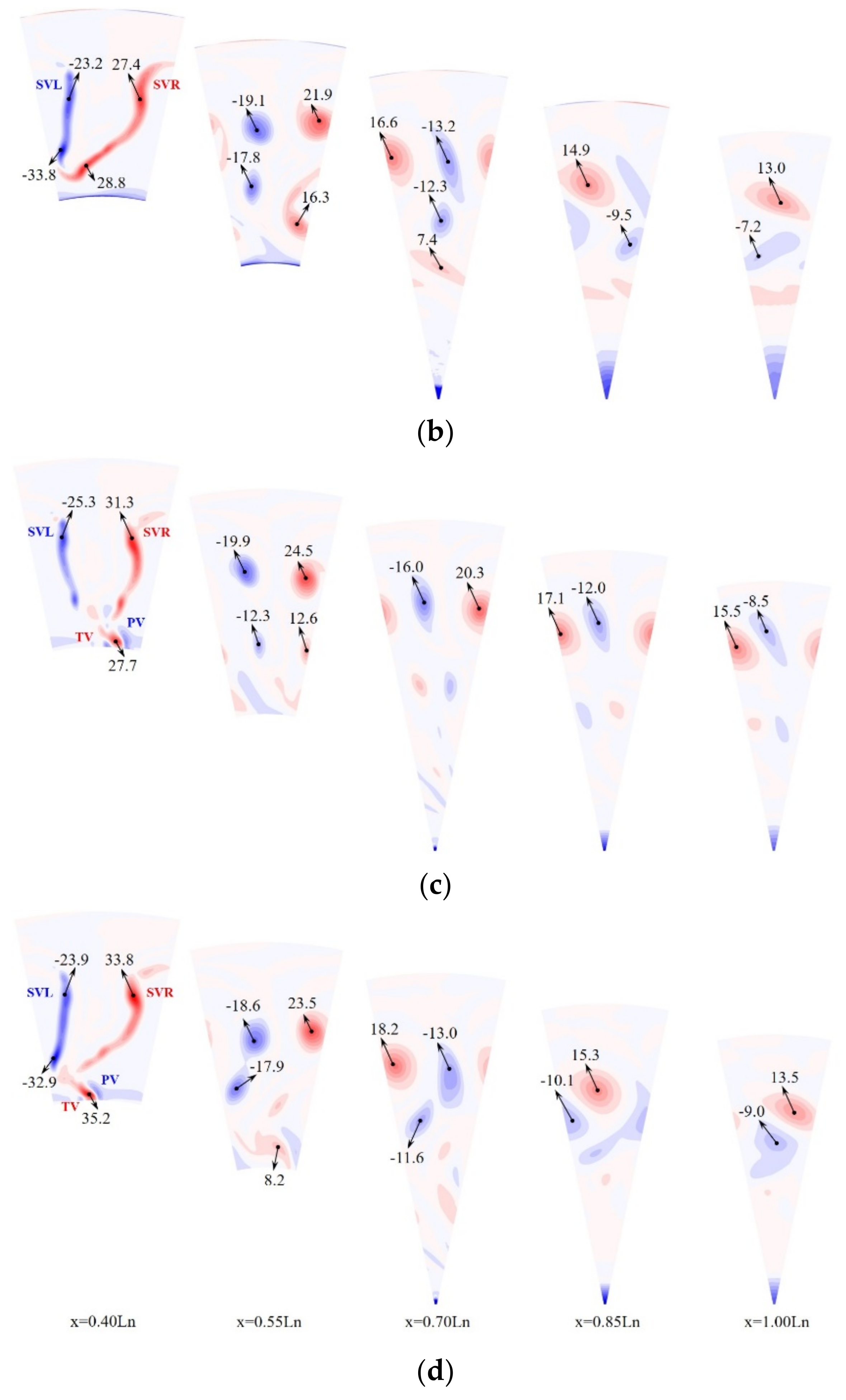
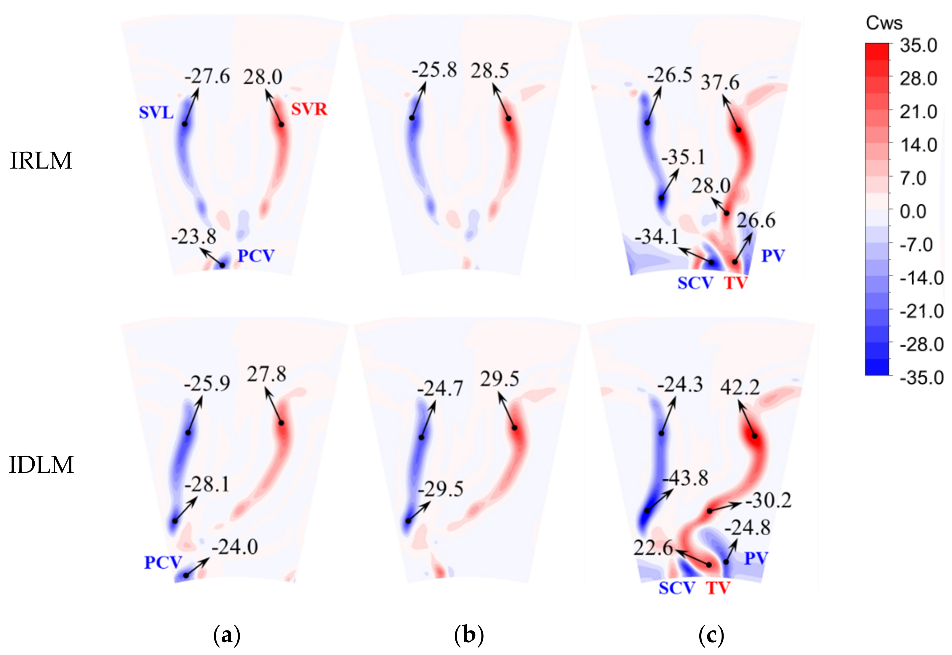
Figure 12 displays the streamwise vorticity contour downstream of the lobed mixers under different conditions with a core inlet swirl 20°. Also, it marks the maximum vorticity values of each vortex core. As the x = 0.4 Ln section is located 5 mm downstream of the lobed mixers, jet mixing between bypass flow and core flow has just started, and streamwise vorticity has not yet dissipated on this section. Therefore, it can approximately characterize the total strength of streamwise vortices under this condition. In this section, the maximum vorticity values of the left streamwise vortex (SVL) and right streamwise vortex (SVR) downstream of DLM are −33.8 and 27.4, respectively, greater than those in the RLM case. It indicates that the streamwise vortices downstream of DLM are stronger than those in the RLM case. This is because (1) when designing DLM, the authors intentionally designed an outlet metal angle to retain a certain residual swirl downstream of the lobed mixer, which is beneficial for enhancing streamwise vortices; (2) as shown in Figure 9, the residual swirl downstream of DLM is stronger than that in the RLM case, further enhancing streamwise vortices in this case. Additionally, due to the geometric bending of DLM, its SVR range is larger than that in the RLM case. All these factors show that the scale and strength of streamwise vortices are greater than those in the RLM case, inevitably enhancing jet mixing efficiency in this case. With interaction between streamwise vortices, maximum vorticity in RLM and DLM cases first decays sharply to x = 0.7 Ln section and then their decay rates slow down, indicating that dissipation of streamwise vortex mainly occurs upstream of x = 0.7 Ln section. The decay rate of maximum streamwise vorticity downstream of DLM is greater than that in the RLM case. Finally, the maximum vorticity values at the x = 0.85 Ln and 1.00 Ln sections downstream of RLM and DLM are roughly equivalent. The increase in the decay rate of streamwise vorticity is related to their greater initial strength and stronger residual swirl downstream of DLM. Under the influence of a strong residual swirl, a streamwise vortex is entrained and moved to the right side. On the x = 0.7 Ln section, it can be seen that SVR downstream of DLM almost entirely moves out from the right side, while SVR downstream of RLM just crosses the right boundary. This entrainment process will further enhance interaction between streamwise vortices and azimuthal vortices, thus accelerating the decay rate of streamwise vortices downstream of DLM to a certain extent. On sections downstream of the central body (X > 0.7 Ln), there are strong vorticity regions at the center of this section in both RLM and DLM cases, as shown by the blue vortex band at the sector center on the x = 0.7 Ln–1.00 Ln section. This is because strong residual swirls remain between the lobe trough and central body in both RLM and DLM cases, which are further accelerated by the central body and finally induce a backflow downstream of the central body. This backflow corresponds to the high vorticity region at the sector center.
After integrating OGV, the maximum values of total streamwise vorticity in the two integrated lobed mixers have increased significantly: compared to RLM and DLM cases, maximum streamwise vorticity has increased by 9.3 and 6.4 in IRLM and IDLM cases, respectively. This is because the core flow between the lobe crest and the central body is involved in radial secondary flow inside the lobed mixer after integrating OGV. In other words, the lower boundary of streamwise circulation integral downstream of the lobed mixer is expanded from the lobe trough to the central body, greatly enhancing streamwise vortices downstream of the integrated lobed mixer. Upstream of x = 0.7 Ln section, the decay rate of maximum streamwise vorticity of SVL and SVR in IRLM and IDLM cases is greater than those in RLM and DLM cases. While maximum vorticity decay rates in all four cases are roughly equivalent downstream of x = 0.7 Ln section, after integrating OGV, strong trailing edge shedding vortices and passage vortices downstream of IOGV interact with streamwise vortices, accelerating dissipation of streamwise vortices in the corresponding area: (1) as shown on x = 0.55 Ln section in Figure 12c,d, maximum vorticity in this area is 12.6 and 8.2 in IRLM and IDLM cases respectively, while they are 13.5 and 17.8 in RLM and DLM cases; (2) on x = 0.7 Ln section, streamwise vortices in this area have dissipated completely in IRLM and IDLM cases, while there are still clear vortex cores in RLM and DLM cases. Downstream of the central body, the range and maximum vorticity value of the high vortex band at the sector center for IRLM and IDLM cases are significantly reduced compared to those in RLM and DLM cases. This is because integrated lobed mixers effectively suppress leakage swirling flow between the lobe trough and the central body, reducing its flow angle from 20° to below 7° (Figure 9). Even if this weak leakage swirling flow is accelerated by a central body, it cannot induce backflow downstream of the central body, which will be beneficial for reducing total pressure loss and thrust loss of the exhaust system.
Compared to maximum vorticity (Cws, max = 31.3) in the IRLM case, maximum streamwise vorticity in the IDLM case increases by 8% on x = 0.4 Ln section, and then the decay rate of maximum vorticity shown on downstream sections is also greater than that in IRLM case. As analyzed above, this is mainly due to the design concept of DLM, which reserves a certain strength of residual swirling flow. In addition, the strength of the trailing edge shedding vortex downstream of IOGV in the IDLM case is also greater than that in the IRLM case, with their maximum values on x = 0.4 Ln section being 35.5 and 27.7, respectively. Therefore, compared to the IRLM case, stronger streamwise vortices interact with stronger trailing edge shedding vortex in the IDLM case, inevitably accelerating the dissipation of streamwise vortices in this area: streamwise vortices in the IDLM case have almost dissipated on x = 0.55 Ln section, while there are still two clear vortex cores on this section in IRLM case until x = 0.7 Ln section.
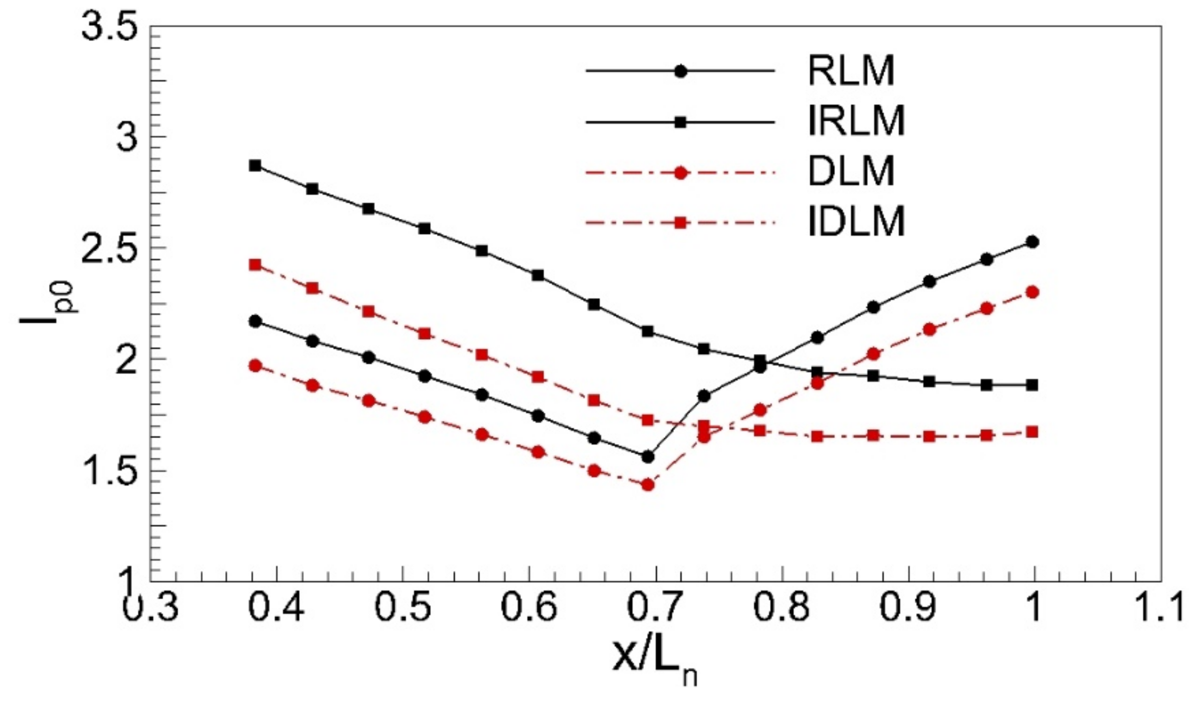
Figure 13 shows the total pressure mixing index distribution in four cases with a core inlet swirl 20°. Mixing indexes of two non-integrated lobed mixers show a trend of first linear decrease and then linear increase: (1) in the region from the trailing edge of the lobed mixer to the tail edge of the central body (0.38 < x/Ln < 0.7), jet mixing is mainly dominated by streamwise vortices and mixing index continues to decrease with vortices interaction, indicating that jet uniformity has been continuously improved; (2) while downstream of the central body (x/Ln > 0.7), mixing index increases continuously, indicating that jet uniformity is deteriorated due to backflow induced by leakage swirling flow between lobe trough and the central body. On each section, the mixing index in the DLM case is smaller than that in the RLM case, indicating that jet downstream DLM has better uniformity. After integrating with OGV, due to the influence of passage vortex and trailing edge shedding vortex, initial mixing indexes are larger than those downstream of non-integrated lobed mixers. As shown in x = 0.4 Ln section in Figure 13, the mixing indexes of IRLM and IDLM are 2.87 and 2.42, respectively, while RLM and DLM are 2.17 and 1.97, respectively. In the region of x < 0.7 Ln, mixing indexes of integrated lobed mixers also show a linear decrease trend. Their decay rates are greater than those of non-integrated lobed mixers, indicating that jet mixing downstream of integrated lobed mixer is more intense than those downstream of non-integrated lobed mixer, consistent with the previous conclusion that integrated lobed mixers are beneficial for accelerating jet mixing by enhancing streamwise vortices. Since integrated lobed mixer suppresses backflow downstream of the central body, mixing indexes downstream of x = 0.7 Ln section in integrated lobed mixers gradually decrease and tend to stable values. Compared to the IRLM case, a smaller initial mixing index on x = 0.4 Ln section in the IDLM case indicates better initial jet uniformity. On x = 0.7 Ln section, the decay rate of the mixing index in the IDLM case slows down significantly. It tends to be stable downstream of x = 0.83 Ln section, while the mixing index still maintains a large decay rate in the region of 0.7 Ln < x < 0.83 Ln for IDLM case, then slows down slightly, and finally tends to stable value on x = 0.96 Ln section. This indicates that most jet mixing has been almost completed upstream of x = 0.7 Ln section in IDLM cases, while jet mixing continues until x = 0.83 Ln section in IRLM case. That is to say, jet mixing in the IDLM case is faster than in the IRLM case. On the nozzle outlet (x = 1.0 Ln), the mixing index (Ip0 = 1.67) in the IDLM case is smaller than that (Ip0 = 1.88) in the IRLM case, indicating that the jet flow of the IDLM case is more uniform at the outlet.
Table 2 shows the total pressure loss and Relative Thrust (Tre) on the nozzle outlet for the four cases with core inlet swirl of 20°, and also gives their gain (ΔY and ΔTre) relative to those of the RLM case. The total pressure loss in the DLM case has increased by 7.78% compared with that of the RLM case, which may be related to the enhanced jet mixing and the stronger leakage swirl between the lobe trough and central body in the DLM case. Similarly, it can also see that the total pressure loss in the IDLM case is greater than that of the IRLM case. However, the total pressure losses of the two integrated lobed mixers are significantly lower than those of the non-integrated lobed mixers due to the effective suppression of leakage swirling flow.
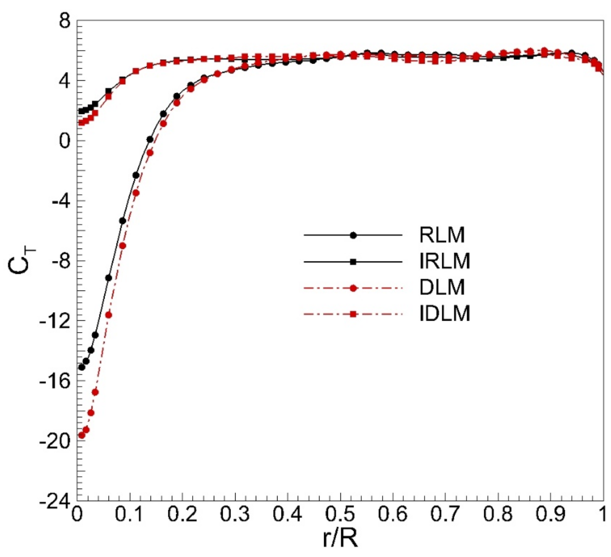
Figure 14 shows the radial distribution of pitch-wise mass-averaged thrust coefficient on the nozzle outlet for the four cases with a core inlet swirl of 20°. Due to the strong swirling flow and the wake of the central body, there are thrust deficit regions at the jet center for all cases, while the thrust coefficients are roughly equivalent in the outer ring (r > 0.4R). Compared with the RLM case, the depth and width of the thrust deficit region in the DLM case are greater due to the more leakage swirling flow between the central body and the raised tough ridge line of DLM. Although the thrust loss in the center area is greater in the DLM case, its overall thrust coefficient has increased by 1.32% (Table 2) compared with the RLM case, indicating that the enhanced suppression effect on the inlet swirl of the outer-ring is also beneficial to improve the thrust in the DLM case. After integrating with OGV, due to the suppression effect of IOGV on the leakage swirling flow between the lobe trough and central body, the depth and width of the thrust deficit area in the jet center have been significantly reduced compared with the non-integrated lobed mixers. Compared with IRLM, although the thrust loss in the jet center is greater in the IDLM case (similar to the DLM case), its total thrust gain relative to the RLM case is 3.18% (Table 2) and is still greater than that (ΔTre = 3.01% in Table 1) of the IRLM case, indicating that IDLM has the best comprehensive effect of improving the output thrust of the exhaust system.

3.2. Performance of IDLM on off-Design Condition

Figure 15 presents the radial distribution of the tangential flow angle on the x = 0.4 Ln section downstream of the two integrated lobed mixers for different inlet swirl cases. When the inlet swirl is less than 20°, that is, under conditions of positive attack angle, flow angles in the area (0 < r/H < 0.2) corresponding to the Integrated Outlet Guide Vane (IOGV) in Integrated Radial Lobed Mixer (IRLM) cases increase radially, but their maximum values remain between 0° and 5°, which is insufficient to induce backflow downstream of the central body. For the region corresponding to the lobed mixer: (1) when 0.2 < r/H < 0.4, the flow angle remains relatively stable at certain values within the range of 0–5°, and these stable values increase with increasing inlet swirl; (2) when 0.4 < r/H < 0.79, flow angle decreases continuously and approaches 0°. This indicates that the IRLM retains a good ability to organize inlet swirl under positive attack angle conditions. Compared to IRLM cases, the flow angle in the region 0 < r/H < 0.2 for Integrated Diagonal Lobed Mixer (IDLM) cases is lower, indicating that the IDLM has superior de-swirl ability compared to the IRLM. In the region 0.26 < r/H < 0.55, flow angles for both mixers are relatively stable at fixed values, and these fixed values increase with increasing inlet swirl. In this region, fixed flow angles downstream of the IDLM are greater than those downstream of the IRLM for cases with core inlet swirl < 20°. The increase in these residual flow angles enhances streamwise vortices, suggesting that the IDLM can effectively utilize inlet swirl to accelerate jet mixing under positive attack angle conditions. Under conditions of negative attack angle (inlet swirl > 20°), flow angle distributions downstream of the two integrated lobed mixers exhibit double-hump shapes, with the Integrated Outlet Guide Vane (IOGV) corresponding to the first hump region and the lobed mixer corresponding to the second. The flow angle in the first hump region is greater than that in the second, indicating that the de-swirl ability of the IOGV is weaker than that of the lobed mixer under negative attack angle conditions. Flow angles in both hump regions for the Integrated Diagonal Lobed Mixer (IDLM) are greater than those for the Integrated Radial Lobed Mixer (IRLM). The difference between them increases with increasing inlet swirl: (1) an increase in flow angle in the first hump region for the IDLM indicates that raising the trough ridge line further increases IOGV loading and its deviation angle, reducing its de-swirl ability. In particular, in the case with a core inlet swirl of 35°, the peak value for its outlet flow angle reaches 17.4°, which may induce backflow and increase thrust loss and total pressure loss; (2) an increase in peak flow angle in the second hump region may be related to outlet metal angle reserved by the IDLM, which will enhance streamwise vortices and accelerate jet mixing but may also increase mixing loss.
To compare the influence of inlet swirl on vortex structure downstream of the lobe mixer under non-design conditions, Figure 16 presents streamwise vorticity contours on the x = 0.4 Ln section downstream of the Integrated Radial Lobed Mixer (IRLM) and Integrated Diagonal Lobed Mixer (IDLM) in cases with core inlet swirls of 0°, 10° and 30°. For both lobed mixers, peak vorticity and the range of Streamwise Vortex Left (SVL) and Streamwise Vortex Right (SVR) increase with increasing inlet swirl, indicating that an increase in inlet swirl is beneficial for enhancing streamwise vortex downstream of the lobed mixers. Under identical conditions, peak streamwise vorticity for the IDLM is greater than that for the IRLM. For example, in the case with a core inlet swirl of 30°, the maximum streamwise vorticities for the IRLM and IDLM are 37.6 and 42.2, respectively. This suggests that even under non-design conditions, the de-swirling lobed mixer can effectively utilize inlet swirl to enhance streamwise vortices further and accelerate jet mixing. In the region downstream of the Integrated Outlet Guide Vane (IOGV), flow separation and corner vortex on the pressure surface of the IOGV (as indicated by PCV in the case with a core inlet of 0°) become dominant factors in jet mixing with increasing positive attack angle. Comparing cases with different lobed mixers, peak values and ranges for this corner vortex are approximately equivalent, indicating that it is largely unaffected by the type of lobed mixer. With increasing negative attack angle, ranges for Passage Vortex (PV) and Trailing Edge Shedding Vortex (TV) downstream of IOGV are significantly larger than those downstream of corresponding lobed mixers in cases with a core inlet swirl of 20°. This indicates that increasing the negative attack angle can enhance PV and TV to some extent. In this section, peak vorticity values for both lobed mixers in cases with negative attack angles are lower than those with a core inlet swirl of 20°. This may be due to accelerated vortex dissipation in these cases. Compared to Integrated Radial Lobed Mixer (IRLM) cases, the range of Passage Vortex (PV) and Trailing Edge Shedding Vortex (TV) in Integrated Diagonal Lobed Mixer (IDLM) cases under a negative attack angle is significantly larger. This is related to the degraded de-swirl ability of the Integrated Outlet Guide Vane (IOGV) in IDLM cases with a negative attack angle.
To comprehensively evaluate the influence of the inlet swirl on the mixing efficiency of the two integrated lobe mixers, Figure 17 presents the distributions of the total pressure mixing index for various cases. Under conditions of positive attack angle, the Ip0 trends for both lobed mixers are generally consistent: (1) they decrease linearly until the x = 0.828 Ln section; (2) downstream of this section, their decay rates slow down due to the influence of the central body’s wake, but they still maintain a linear downward trend. In ascending order of Ip0 on each section under positive attack angle conditions, the order of cases for the Integrated Radial Lobed Mixer (IRLM) is 5°, 10°, 0° and 15°. This indicates that jet uniformity downstream of the IRLM in the 5° case is optimal among all cases with a positive attack angle. The Ip0 trend for each positive attack angle condition is consistent with the IRLM: jet uniformity in the 5° case is optimal among all Integrated Diagonal Lobed Mixer (IDLM) cases with positive attack angles. The Ip0 for the IDLM under its worst positive attack angle condition (α = 15°) is still lower than that of the best IRLM case (α = 5°). This suggests that overall jet uniformity downstream of the IDLM is superior to that downstream of the IRLM. In cases with a negative attack angle (α > 20°), the Ip0 on the x = 0.4 Ln section downstream of both lobed mixers is lower than that in cases with positive attack angle, and Ip0 on the same section decreases with increasing inlet swirl for different lobed mixers. This may be due to the enhancement of pre-mixing downstream of the scalloped notch by inlet swirl. Under conditions of negative attack angle, the Ip0 for the Integrated Radial Lobed Mixer (IRLM) decreases linearly until the x = 0.7 Ln section. Then it increases linearly downstream of this section due to backflow and wakes downstream of the central body. As a result, the Ip0 at the nozzle outlet in cases with a negative attack angle is greater than that of the IRLM case with a core inlet swirl of 5°. This suggests that under negative attack angle conditions, the increase in jet uniformity resulting from enhanced mixing in IRLM cases with negative attack angles cannot offset the rise in jet non-uniformity caused by backflow and wake downstream of the central body. On the x = 0.4 Ln section, the Ip0 for the Integrated Diagonal Lobed Mixer (IDLM) is lower than the IRLM under identical negative attack angle conditions. This indicates that the enhancement effect of the inlet swirl on pre-mixing of the scalloped notch in IDLM cases with a negative attack angle is superior to that in IRLM cases. Similarly, in the region 0.4 Ln < x < 0.7 Ln, both Ip0 and its decay rate for the IDLM are lower than those for the corresponding IRLM case. In the region 0.7 Ln < x < 1.0 Ln, increases in Ip0 for IDLM cases is significantly less than for IRLM cases. This suggests that even though higher residual swirl around the central body in IDLM cases with negative attack angle (as shown in Figure 15) induces larger backflow downstream of the central body compared to corresponding IRLM cases, overall jet uniformity for the IDLM remains superior to that for the IRLM.
Figure 18 illustrates the thrust coefficient and total pressure loss for the two-lobed mixers at the outlet under varying inlet swirl conditions. The thrust coefficient is calculated as the thrust gain relative to the thrust of the Radial Lobed Mixer (RLM) case with a core inlet swirl of 20°. The maximum thrust gain for both lobed mixers occurs when the core inlet swirl equals 0°. As the core inlet swirl increases, the thrust gain decreases and even becomes negative when the inlet swirl exceeds 25°. Under conditions of positive attack angle, the thrust gain for the Integrated Diagonal Lobed Mixer (IDLM) is approximately equivalent to that of the Integrated Radial Lobed Mixer (IRLM). However, under conditions of negative attack angle, the thrust coefficient for the IDLM is significantly greater than that of the IRLM, with a maximum difference of 2.15% occurring in the case with a core inlet of 35°. This indicates that the enhanced de-swirl ability of the IDLM is beneficial for increasing its thrust under non-design conditions, particularly under negative attack angle conditions.
Under conditions of positive attack angle, the total pressure loss for both lobed mixers remains relatively constant and is approximately lower than that observed in the inlet swirl 20° case. However, as the negative attack angle increases, there is a sharp increase in the total pressure loss for both lobed mixers. This may be attributed to the growth of separation bubbles on the suction surface of the Integrated Outlet Guide Vane (IOGV) and enhanced backflow downstream of the central body. Compared to the Integrated Radial Lobed Mixer (IRLM) cases, there is a slight increase in total pressure loss for the Integrated Diagonal Lobed Mixer (IDLM) under various conditions. This may be due to more intense mixing downstream of the IDLM under each condition.

4. Conclusions

In this study, the mixing mechanism and performance of a novel structured lobed exhaust system are investigated through numerical methods utilizing the RANS and SST models. This exhaust system comprises a de-swirling lobed mixer and integrated OGVs. Following optimization, the optimal integrated position for the OGVs was determined to be along the centerline of the lobes’ trough and in close proximity to the exit plane of the lobed mixer.
The de-swirling lobed mixer significantly improves the tolerance to inlet swirl, and the reserved outlet flow angle of a certain value is conducive to enhancing the streamwise vortices and accelerating the jet mixing. After DLM is integrated with the OGVs, it expands the radial range of the secondary flow in the inner channel, which is conducive to increasing the strength and scale of streamwise vortices. The integrated OGVs further enhance the de-swirling ability of the lobed mixer exhaust system, significantly suppressing the leakage swirl between the trough and the center body and the backflow downstream of the center body, which is beneficial to reduce the total pressure loss and thrust loss of the exhaust system. To maintain the same number of OGV as that of lobes, the aerodynamic loading of OGV is very high, which can lead to flow separation, large-scale passage vortices, and corner vortices and increase its design difficulty. The radial pressure gradient inside the lobed mixer enhances the passage vortex in the IOGV channel, which is conducive to accelerating the jet mixing between the central body and lobe’s trough to a certain extent. But the passage vortex also leads to an increase in total pressure loss.
Under design conditions, the integrated de-swirling lobed mixer (IDLM) can increase thrust by 3.18% and reduce total pressure loss by 31.17% compared with the reference lobed mixer. Even under off-design conditions, the IDLM can still effectively use the inlet swirls to enhance streamwise vortices and accelerate jet mixing. Within the operating range studied in this paper, the outlet jet uniformity of IDLM is better than that of IRLM. Moreover, the IDLM has a significantly better tolerance to inlet swirl than the IRLM, especially under negative attack angle conditions (α > 20°). In the case of core inlet swirl of 35°, the IDLM can reduce thrust loss by 2.15% compared with the IRLM.

Author Contributions

Conceptualization, Z.L. and Y.Z.; methodology, H.D.; validation, Z.L.; formal analysis, X.O.; investigation, Z.L. and H.D.; supervision, X.L., G.X. and J.Z. All authors have read and agreed to the published version of the manuscript.

Funding

This research was funded by the “National Science and Technology Major Project (J2019-II-0007-0027)” and by the “Science Center for Gas Turbine Project (P2022-DC-II-001-001)”.

Data Availability Statement

Not applicable.

Conflicts of Interest

The authors declare no conflict of interest.

Nomenclature

RLMScalloped Reference Lobed MixerCwaAzimuthal Vorticity Coefficient
DLMScalloped de-swirling Lobed MixerCwsStreamwise Vorticity Coefficient
IRLMIntegrated RLMCp0Total Pressure Coefficient
IDLMIntegrated DLMCTThurs Coefficient
OGVOutlet Guide VanewaAzimuthal Vorticity
IOGVIntegrated Outlet Guide VanewsStreamwise Vorticity
LPTLow-Pressure TurbineTThrust
x, y, zx, y, and z CoordinateTreThe Relative Thrust
u, v, wVelocity in the x, y and z-Directionucore,inAxial Velocity of Core Inlet
αInlet Swirl Angle, °DhHydraulic Diameter of Core Exit
HheightIgMixing Index
HChannel HeightIp0Total Pressure Mixing Index
LnLength of Nozzley+Non-dimensional wall distance
P0Total Pressure, PaYTotal Pressure Loss
PsStatic Pressure, PaRRadius of Bypass Nozzle

References

  1. Povinelli, L.; Anderson, B.; Gerstenmaier, W. Computation of three-dimensional flow in turbofan mixers and comparison with experimental data. In Proceedings of the 18th Aerospace Sciences Meeting, Pasadena, CA, USA, 14–16 January 1980. [Google Scholar]
  2. Blackmore, W.L.; Thompsont, C.E.; Thompson, C.E. Three-dimensional viscous analysis of ducts and flow splitters. J. Aircr. 1983, 20, 385–389. [Google Scholar] [CrossRef]
  3. Paterson, R.W. Turbofan Forced Mixer-Nozzle Internal Flowfield I—A Benchmark Experimental Study; NASA Contractor Report; NASA: Washington, DC, USA, 1982; NASA-CR-3492.
  4. Eckerle, W.A.; Sheibani, H.; Awad, J. Experimental Measurement of the Vortex Development Downstream of a Lobed Forced Mixer. J. Eng. Gas Turbines Power 1992, 114, 63–71. [Google Scholar] [CrossRef]
  5. Werle, M.J.; Presz, J.W.; Paterson, R.W. Flow structure in a periodic axial vortex array. In Proceedings of the 25th AIAA Aerospace Sciences Meeting, Reno, NV, USA, 24–26 March 1987. [Google Scholar]
  6. Manning, T.A. Experimental Studies of Mixing Flows with Streamwise Vorticity. Master’s Thesis, Massachusetts Institute of Technology, Cambridge, MA, USA, 1991. [Google Scholar]
  7. McCormick, D.C.; Bennett, J.C., Jr. Vortical and Turbulent Structure of a lobed Mixer Free Shear Layer. AIAA J. 1994, 32, 1852–1859. [Google Scholar] [CrossRef]
  8. Ukeiley, L.; Varghese, M.; Glauser, M.; Valentine, D. Multifractal analysis of a lobed mixer flowfield utilizing the proper orthogonal decomposition. AIAA J. 1992, 30, 1260–1267. [Google Scholar] [CrossRef]
  9. Ukeiley, L.; Glauser, M.; Wick, D. Downstream Evolution of Proper Orthogonal Decomposition Eigen functions in a Lobed Mixer. AIAA J. 1993, 31, 1392–1397. [Google Scholar] [CrossRef]
  10. Belovich, V.M.; Samimy, M. Mixing Processes in a Coaxial Geometry with a Central Lobed Mixer-Nozzle. AIAA J. 1997, 35, 838–841. [Google Scholar] [CrossRef]
  11. Kozlowski, H.; Larkin, M. Energy Efficient Engine—Exhaust Mixer Model Technology Report; NASA Contractor Report; NASA: Washington, DC, USA, 1982; NASA-CR-165459.
  12. Schwartz, I.R. Jet noise suppression by swirling the jet flow. In Proceedings of the Aeroacoustics Conference, Seattle, WA, USA, 15–17 October 1973. [Google Scholar]
  13. Schwartz, I.R. Minimization of jet and core noise of a turbojet engine by swirling the exhaust flow. In Proceedings of the 2nd Aeroacoustics Conference, Hampton, VA, USA, 24–26 March 1975. [Google Scholar]
  14. Carpenter, P.W.; Johannesen, N.H. An Extension of One-Dimensional Theory to Inviscid Swirling Flow through Choked Nozzles. Aeronaut. Q. 1975, 26, 71–87. [Google Scholar] [CrossRef]
  15. Lu, H.; Ramsay, J.; Miller, D. Noise of Swirling Exhaust Jets. AIAA J. 1977, 15, 642–646. [Google Scholar] [CrossRef]
  16. Knowles, K.; Carpenter, P.W. Subcritical swirling flows in convergent, annular nozzles. AIAA J. 1989, 27, 184–191. [Google Scholar] [CrossRef]
  17. Knowles, K.; Carpenter, P.W. Use of swirl for flow control in propulsion nozzles. J. Propuls. Power 1990, 6, 158–164. [Google Scholar] [CrossRef]
  18. Lei, Z.; Mahallati, A.; Cunningham, M.; Germain, P. Influence of Inlet Swirl on the Aerodynamics of a Model Turbofan Lobed Mixer. In Proceedings of the ASME 2010 International Mechanical Engineering Congress and Exposition, Vancouver, BC, Canada, 12–18 November 2010. IMECE2010-39116. [Google Scholar]
  19. Lei, Z.J.; Mahalatti, A.; Cunningham, M.H.; Germain, P. Effects of Core Flow Swirl on Flow Characteristics of an Scalloped Lobed Force Mixer. J. Eng. Gas Turbines Power. 2012, 134, 111201. [Google Scholar] [CrossRef]
  20. Lei, Z.J.; Mahalatti, A.; Yang, H. Numerical simulation of the aerodynamics of a model turbofan lobed mixer with inlet swirl. In Proceedings of the 20th ISABE Conference, Göteborg, Sweden, 12–16 September 2011. ISABE2011-1822. [Google Scholar]
  21. Lei, Z.J. Experimental Study on the Mixing Mechanism of Lobed Mixer with Inlet Swirl in Model Turbofan Engines. Ph.D. Thesis, Chinese Academy of Sciences, Beijing, China, 2011. (In Chinese). [Google Scholar]
  22. Lei, Z.J.; Zhang, Y.F.; Zhu, Z.H.; Zhu, J.Q. Numerical research on the mixing mechanism of lobed mixer with inlet swirl in linear radial distribution. Proc. Inst. Mech. Eng. Part A J. Power Energy 2015, 229, 280–297. [Google Scholar] [CrossRef]
  23. Chai, M. Investigation on the Mixing Mechanisms and Design of De-Swirling Lobed Mixer. Master’s Thesis, University of Chinese Academic of Sciences, Beijing, China, 2018. (In Chinese). [Google Scholar]
  24. Chai, M.; Lei, Z.J.; Zhang, Y.F.; Lu, X.G.; Zhu, J.Q. Research on Jet Mixing Mechanism of a New De-Swirling Lobed Mixer. J. Propuls. Technol. 2018, 39, 1965–1973. (In Chinese) [Google Scholar]
  25. Song, Y.K.; Lei, Z.J.; Lu, X.G.; Xu, G.; Zhu, J.Q. The Optimization of a Lobed Mixer with BP Neural Network and Genetic Algorithm. J. Therm. Sci. 2022, 32, 387–400. [Google Scholar] [CrossRef]
  26. Kajishima, T.; Taira, K. Reynolds-Averaged Navier–Stokes Equations. In Computational Fluid Dynamics; Springer: Cham, Switzerland, 2017. [Google Scholar]
Figure 1. Models of Lobed Mixers.
Energies 16 04394 g001
Figure 2. Parameters of Reference Lobed mixer.
Energies 16 04394 g002
Figure 3. Parameters of Scalloping Notch.
Energies 16 04394 g003
Figure 4. Profile of OGVs.
Energies 16 04394 g004
Figure 5. Performance of IRLM with the Axial Location of the integrated OGV.
Energies 16 04394 g005
Figure 6. Computational Domain.
Energies 16 04394 g006
Figure 7. Mesh of Lobed Mixer.
Energies 16 04394 g007
Figure 8. Comparison Between Experimental Results and Numerical Ones on the x = 1.0 Ln Section for the IRLM Case with an Inlet Swirl of 20°: (a) Radial distribution of tangential flow angle; (b) Radial distribution of total pressure coefficient; (c) Contour of azimuthal vorticity.
Energies 16 04394 g008aEnergies 16 04394 g008b
Figure 9. The radial distribution of the pitch-wise mass-averaged flow angle at the outlet of the lobed mixer (x = 0.4 Ln) for cases with a core inlet swirl of 20°.
Energies 16 04394 g009
Figure 10. The limiting streamlines on the IOGV, central body and the inner surface of different lobed mixers for the cases with inlet swirl of 20°: (a) RLM; (b) DLM; (c) IRLM; (d) IDLM.
Energies 16 04394 g010
Figure 11. The streamwise vorticity contour at different axial sections in the IOGV channel: (a) IRLM; (b) IDLM.
Energies 16 04394 g011
Figure 12. The streamwise vorticity contour downstream of the lobed mixers under different conditions with the core inlet swirl of 20°: (a) RLM; (b) DLM; (c) IRLM; (d) IDLM.
Energies 16 04394 g012aEnergies 16 04394 g012b
Figure 13. The total pressure mixing index in the four cases with a core inlet swirl of 20°.
Energies 16 04394 g013
Figure 14. The radial distribution of pitch-wise mass-averaged thrust coefficient on the nozzle outlet for the four cases with core inlet swirl of 20°.
Energies 16 04394 g014
Figure 15. The radial distribution of the tangential flow angle on the x = 0.4 Ln section downstream of the two integrated lobed mixers for the different inlet swirl cases.
Energies 16 04394 g015
Figure 16. The streamwise vorticity contours on the x = 0.4 Ln section downstream of IRLM and IDLM in the cases with the core inlet swirl of 0°, 10° and 30°: (a) α = 0°; (b) α = 10°; (c) α = 30°.
Energies 16 04394 g016
Figure 17. The distributions of the total pressure mixing index for the various cases.
Energies 16 04394 g017
Figure 18. The thrust coefficient and total pressure loss for the various cases.
Energies 16 04394 g018
Table 1. Boundary Conditions.
LocationBoundary Condition
Core Inletu = 40 m/s
α = 0°, 5°, 10°, 15°, 20°, 25°, 30° and 35°
Bypass Inletu = 30.8 m/s
α = 0°
Far-fieldPs = 101,325 Pa
OutletPs = 101,325 Pa
Solid SurfacesNo-slip Wall
Table 2. The total pressure loss and thrust coefficient on the nozzle outlet for the four cases with core inlet swirl of 20°.
CasesYΔYTreΔTre
RLM24.29%-1.060-
DLM26.18%7.78%1.0741.32%
IRLM15.38%−36.69%1.0923.01%
IDLM16.72%−31.17%1.0943.18%
Disclaimer/Publisher’s Note: The statements, opinions and data contained in all publications are solely those of the individual author(s) and contributor(s) and not of MDPI and/or the editor(s). MDPI and/or the editor(s) disclaim responsibility for any injury to people or property resulting from any ideas, methods, instructions or products referred to in the content.

