
A Review of Power Co-Generation Technologies from Hybrid Offshore Wind and Wave Energy


Abstract
1. Introduction
2. Power Conversion
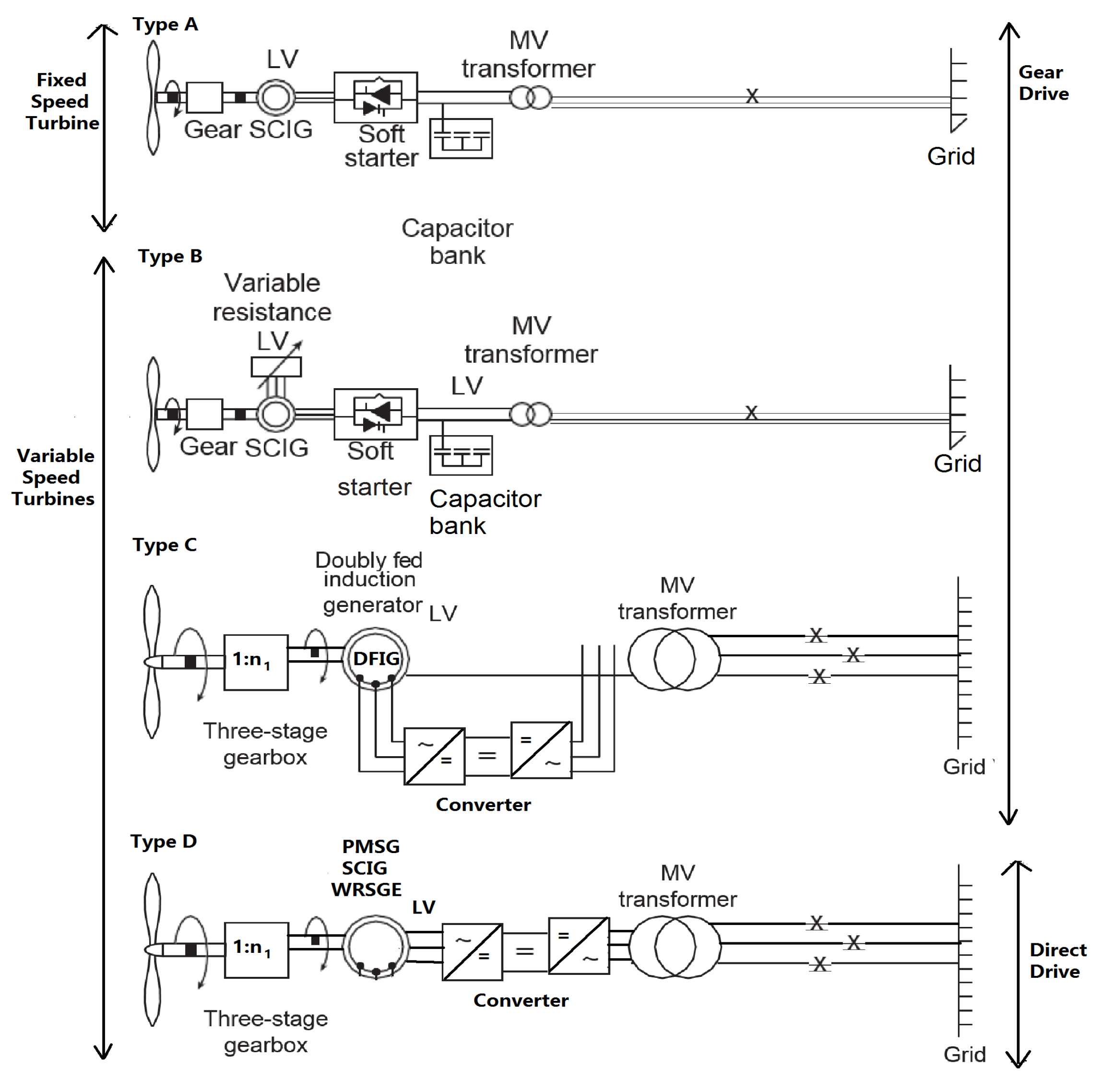
2.1. Offshore Wind

| Wind Turbine Generators | Advantages | Disadvantages |
|---|---|---|
| Fixed speed induction generator | Maximum power production is possible | Minor variation in speed can cause large-torque. Difficult to control the generator torque. Aerodynamic fluctuation is moved to the grid side causing grid faults. High power-driven stress and power losses. |
| DFIG with partially rated power converter | Torque of generator is entirely under control of the power conversion. Speed can be improved by 40%, therefore MPPT is achievable. Very rapid torque control, response time of the torque is from 5 to 50 ms. Aerodynamic fluctuation can be filtered before entering the generator. | Magnetizing current is delivered via the rotor terminal affecting loss of efficiency. High maintenance requirements of slip rings. Aerodynamic fluctuations may cause grid faults. As with PMSG, power-converters are required to connect the grid. |
| PMSG with fully rated power converter | Voltage and reactive-power control are accessible to the grid without upsetting the dynamics of generator. Gearbox can be avoided. | PMSG cannot be straight joined to the grid. Power conversion is required between the generator and the grid. |

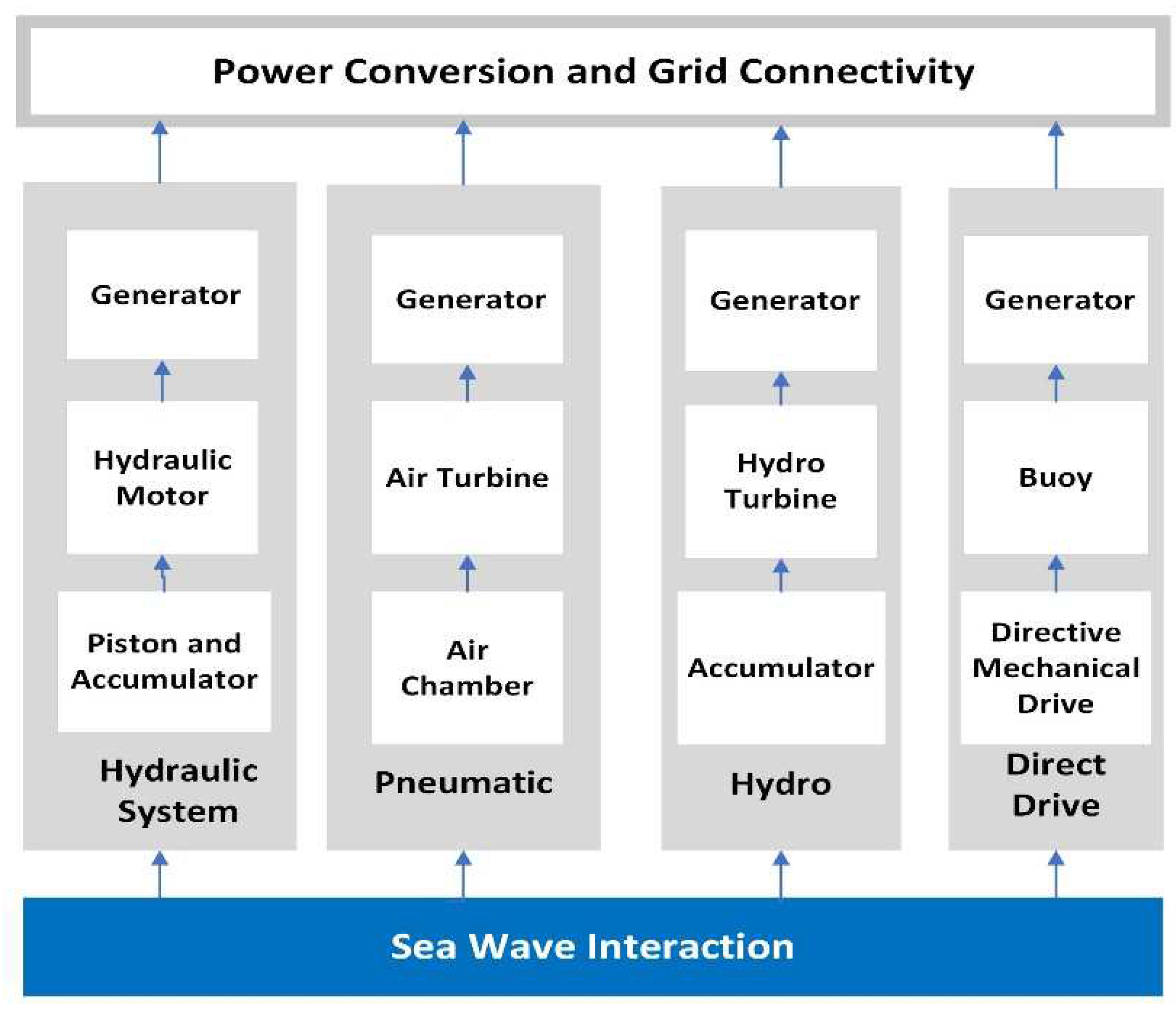
2.2. Wave Energy
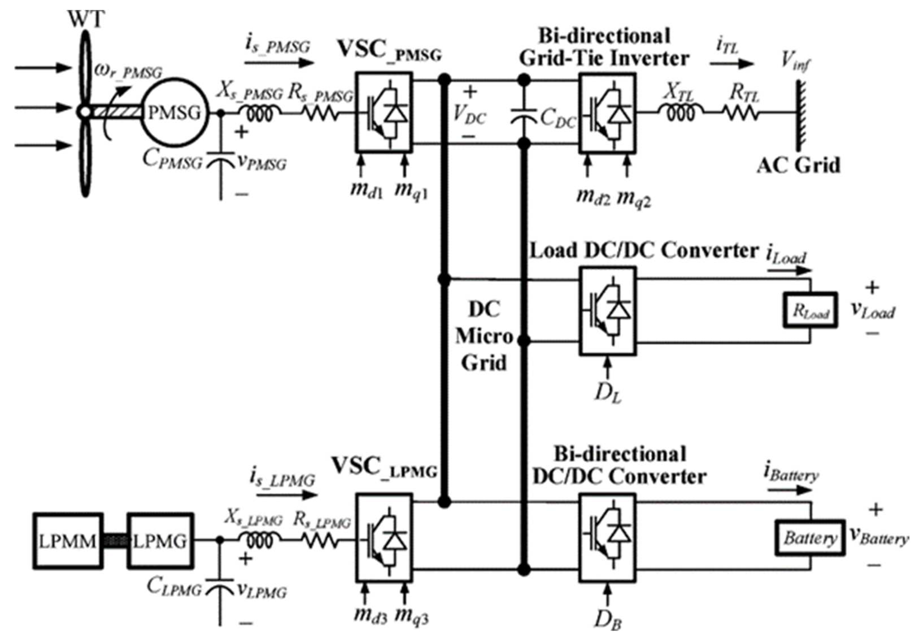
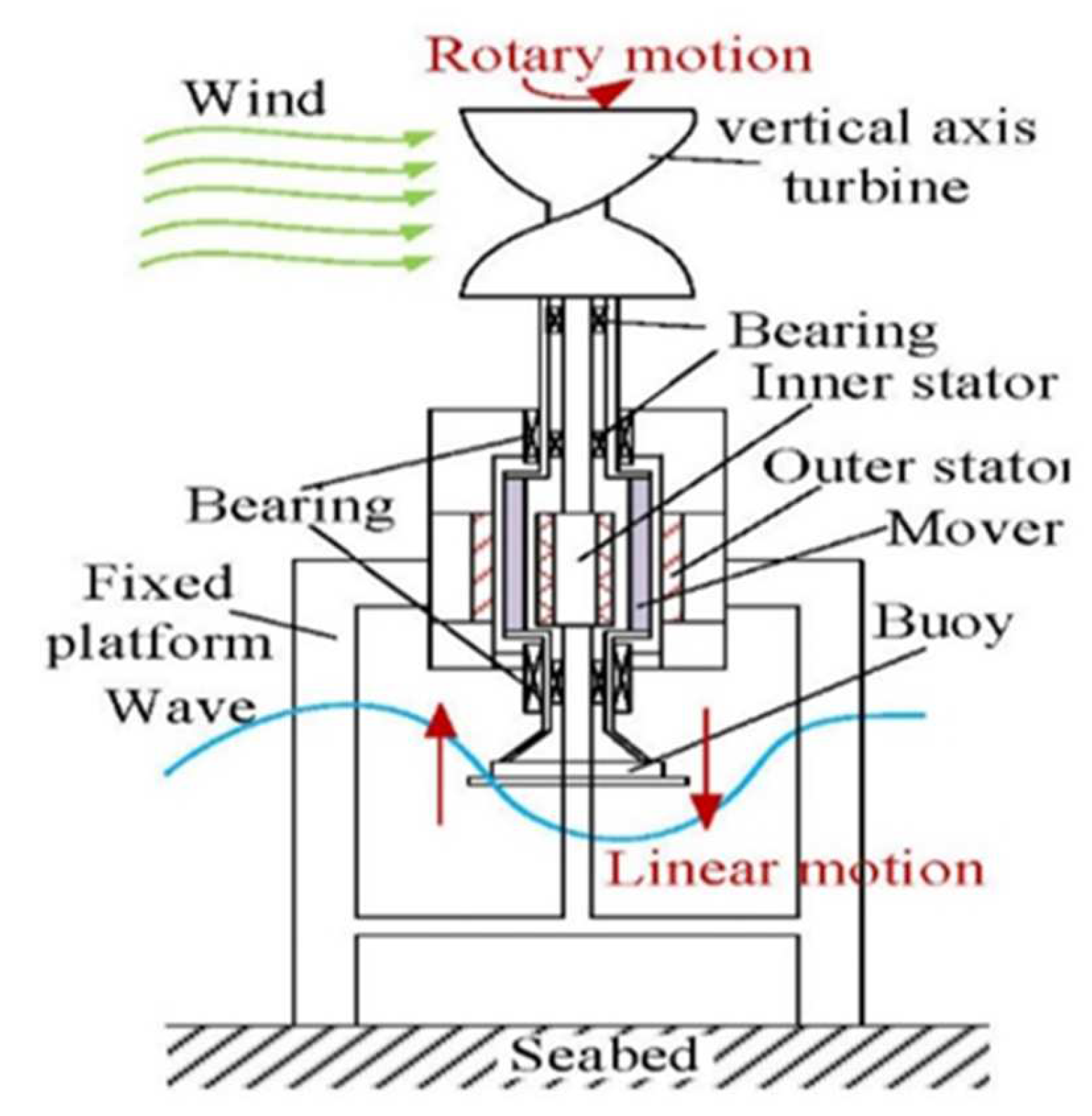
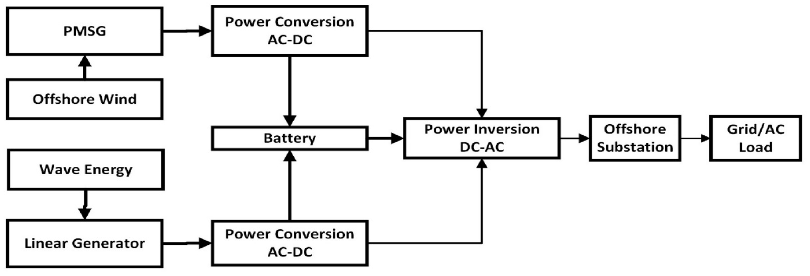
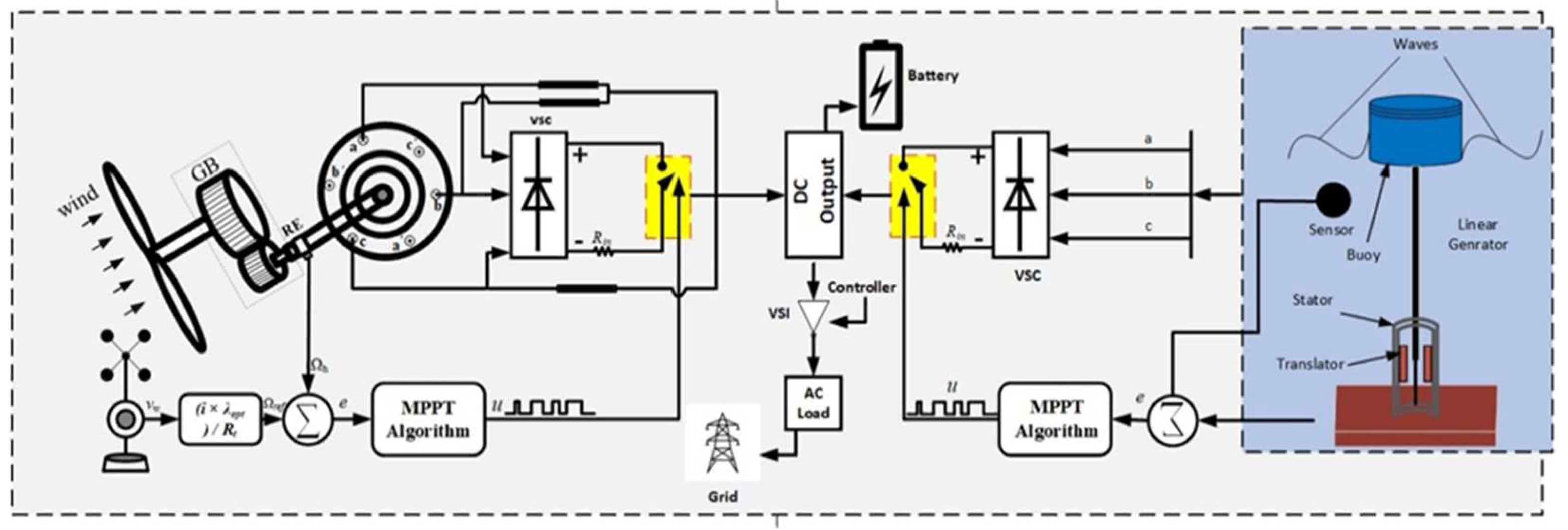
2.3. Power Conversion of HOWWE
3. Response Coupling of HOWWE
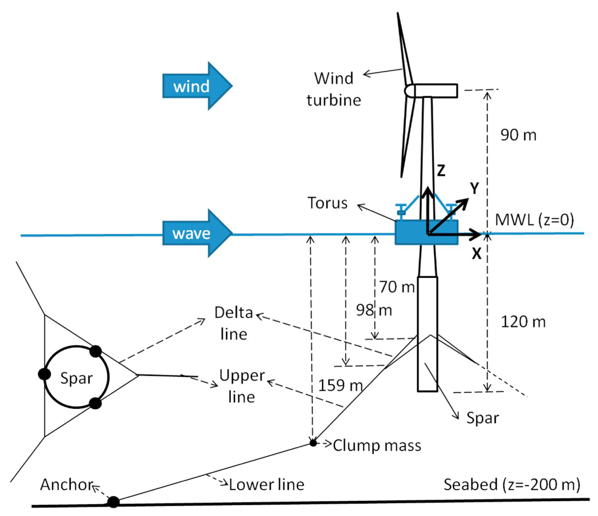
3.1. Spar Torus Combination (STC)
3.2. Wind Wave Float
4. Control Scheme for Co-Generation and Complimentary Generation
5. Colocation of HOWWE
5.1. Statistical Methods for Correlation
5.2. Site Selection
6. Integrated Conversion System
6.1. Bottom Fixed System
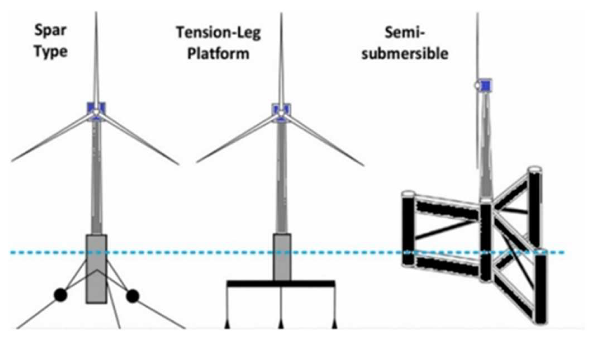
6.2. Floating System
7. Synergies and Challenges
8. Conclusions
Author Contributions
Funding
Institutional Review Board Statement
Informed Consent Statement
Data Availability Statement
Conflicts of Interest
References
- Abas, N.; Kalair, A.R.; Khan, N. Review of fossil fuels and future energy technologies. Futures 2015, 69, 31–49. [Google Scholar] [CrossRef]
- Jin, S.; Greaves, D. Wave energy in the UK: Status review and future perspectives. Renew. Sustain. Energy Rev. 2021, 143, 110932. [Google Scholar] [CrossRef]
- Higgins, P.; Foley, A. The evolution of offshore wind power in the United Kingdom. Renew. Sustain. Energy Rev. 2014, 37, 599–612. [Google Scholar] [CrossRef]
- Bahaj, A.S. Generating electricity from the oceans. Renew. Sustain. Energy Rev. 2011, 15, 3399–3416. [Google Scholar] [CrossRef]
- Astariz, S.; Iglesias, G. Enhancing marine energy competitiveness: Co-located offshore wind and wave energy farms. Coast. Eng. Proc. 2017, 1, 4. [Google Scholar] [CrossRef]
- Contestabile, P.; Di Lauro, E.; Galli, P.; Corselli, C.; Vicinanza, D. Offshore Wind and Wave Energy Assessment around Malè and Magoodhoo Island (Maldives). Sustainability 2017, 9, 613. [Google Scholar] [CrossRef]
- Weiss, C.V.; Guanche, R.; Ondiviela, B.; Castellanos, O.F.; Juanes, J. Marine renewable energy potential: A global perspective for offshore wind and wave exploitation. Energy Convers. Manag. 2018, 177, 43–54. [Google Scholar] [CrossRef]
- Pérez-Collazo, C.; Greaves, D.; Iglesias, G. A review of combined wave and offshore wind energy. Renew. Sustain. Energy Rev. 2015, 42, 141–153. [Google Scholar] [CrossRef]
- Soares, C.G.; Bhattacharjee, J.; Karmakar, D. Overview and prospects for development of wave and offshore wind energy. Brodogradnja 2014, 65, 87–109. [Google Scholar]
- Chen, Z.; Guerrero, J.M.; Blaabjerg, F. A Review of the State of the Art of Power Electronics for Wind Turbines. IEEE Trans Power Electron. 2009, 24, 1859–1875. [Google Scholar] [CrossRef]
- Li, J.; Wang, G.; Li, Z.; Yang, S.; Chong, W.T.; Xiang, X. A review on development of offshore wind energy conversion system. Int. J. Energy. Res. 2020, 44, 9283–9297. [Google Scholar] [CrossRef]
- Perveen, R.; Kishor, N.; Mohanty, S.R. Off-shore wind farm development: Present status and challenges. Renew. Sustain. Energy Rev. 2014, 29, 780–792. [Google Scholar] [CrossRef]
- Ertugrul, N.; Abbott, D. DC is the Future [Point of View]. Proc. IEEE 2020, 108, 615–624. [Google Scholar] [CrossRef]
- Cardenas, R.; Pena, R.; Alepuz, S.; Asher, G. Overview of Control Systems for the Operation of DFIGs in Wind Energy Applications. IEEE Trans. Ind. Electron. 2013, 60, 2776–2798. [Google Scholar] [CrossRef]
- Fernández-Guillamón, A.; Das, K.; Cutululis, N.A.; Molina-García, Á. Offshore Wind Power Integration into Future Power Systems: Overview and Trends. J. Mar. Sci. Eng. 2019, 7, 399. [Google Scholar] [CrossRef]
- Tripathi, S.M.; Tiwari, A.N.; Singh, D. Grid-integrated permanent magnet synchronous generator based wind energy conversion systems: A technology review. Renew. Sustain. Energy Rev. 2015, 51, 1288–1305. [Google Scholar] [CrossRef]
- Tavner, P. Offshore Wind Turbines: Reliability, Availability and Maintenance; Institution of Engineering and Technology: London, UK, 2012. [Google Scholar]
- López, I.; Andreu, J.; Ceballos, S.; de Alegría, I.M.; Kortabarria, I. Review of wave energy technologies and the necessary power-equipment. Renew. Sustain. Energy Rev. 2013, 27, 413–434. [Google Scholar] [CrossRef]
- Magagna, D.; Uihlein, A. Ocean energy development in Europe: Current status and future perspectives. Int. J. Mar. Energy 2015, 11, 84–104. [Google Scholar] [CrossRef]
- Sheng, W.; Alcorn, R.; Lewis, A. On thermodynamics in the primary power conversion of oscillating water column wave energy converters. J. Renew. Sustain. Energy 2013, 5, 23105. [Google Scholar] [CrossRef]
- O’Sullivan, D.; Mollaghan, D.; Blavette, A.; Alcorn, R. Dynamic Characteristics of Wave and Tidal Energy Converters & a Recommended Structure for Development of a Generic Model for Grid Connection; International Energy Agency: Paris, France, 2010.
- Rodríguez, C.A.; Rosa-Santos, P.; Taveira-Pinto, F. Assessment of the power conversion of wave energy converters based on experimental tests. Energy Convers. Manag. 2018, 173, 692–703. [Google Scholar] [CrossRef]
- McGilton, B.; Almoraya, A.A.; Raihan, R.; Crozier, R.; Baker, N.J.; Mueller, M. Investigation into linear generators with integrated magnetic gear for wave energy power take off. J. Eng. 2019, 2019, 5069–5072. [Google Scholar] [CrossRef]
- Li, M.; Jing, X. A bistable X-structured electromagnetic wave energy converter with a novel mechanical-motion-rectifier: Design, analysis, and experimental tests. Energy Convers. Manag. 2021, 244, 114466. [Google Scholar] [CrossRef]
- Karimirad, M. Offshore Energy Structures: For Wind Power, Wave Energy and Hybrid Marine Platforms, 1st ed.; Springer: Cham, Switzerland, 2014. [Google Scholar]
- Chen, W.; Gao, F.; Meng, X.; Chen, B.; Ren, A. W2P: A high-power integrated generation unit for offshore wind power and ocean wave energy. Ocean Eng. 2016, 128, 41–47. [Google Scholar] [CrossRef]
- Karimirad, M.; Koushan, K. WindWEC: Combining wind and wave energy inspired by hywind and wavestar. In Proceedings of the 2016 IEEE International Conference on Renewable Energy Research and Applications (ICRERA), Birmingham, UK, 20–23 November 2016; pp. 96–101. [Google Scholar]
- Marquis, L.; Kramer, M.B.; Kringelum, J.V.; Chozas, J.F.; Helstrup, N.E. Introduction of Wavestar Wave Energy Converters at The Danish Offshore Wind Power Plant Horns Rev 2. In Proceedings of the 4th International Conference on Ocean Energy, Dublin, Ireland, 17–19 October 2012. [Google Scholar]
- Stoutenburg, E.D.; Jenkins, N.; Jacobson, M.Z. Power output variations of co-located offshore wind turbines and wave energy converters in California. Renew. Energy 2010, 35, 2781–2791. [Google Scholar] [CrossRef]
- Wang, L.; Lin, C.-Y.; Wu, H.-Y.; Prokhorov, A.V. Stability Analysis of a Microgrid System with a Hybrid Offshore Wind and Ocean Energy Farm Fed to a Power Grid Through an HVDC Link. IEEE Trans. Ind. Appl. 2018, 54, 2012–2022. [Google Scholar] [CrossRef]
- Lu, S.-Y.; Wang, L.; Lo, T.-M.; Prokhorov, A.V. Integration of Wind Power and Wave Power Generation Systems Using a DC Microgrid. IEEE Trans. Ind. Appl. 2015, 51, 2753–2761. [Google Scholar] [CrossRef]
- Nehrir, M.H.; Wang, C.; Strunz, K.; Aki, H.; Ramakumar, R.; Bing, J.; Miao, Z.; Salameh, Z. A Review of Hybrid Renewable/Alternative Energy Systems for Electric Power Generation: Configurations, Control, and Applications. IEEE Trans. Sustain. Energy 2011, 2, 392–403. [Google Scholar] [CrossRef]
- Nejabatkhah, F.; Li, Y.W. Overview of Power Management Strategies of Hybrid AC/DC Microgrid. IEEE Trans. Power Electron. 2015, 30, 7072–7089. [Google Scholar] [CrossRef]
- Chauhan, A.; Saini, R.P. A review on Integrated Renewable Energy System based power generation for stand-alone applications: Configurations, storage options, sizing methodologies and control. Renew. Sustain. Energy Rev. 2014, 38, 99–120. [Google Scholar] [CrossRef]
- Fathima, A.H.; Palanisamy, K. Optimization in microgrids with hybrid energy systems—A review. Renew. Sustain. Energy Rev. 2015, 45, 431–446. [Google Scholar] [CrossRef]
- Zia, M.F.; Elbouchikhi, E.; Benbouzid, M. Microgrids energy management systems: A critical review on methods, solutions, and prospects. Appl. Energy 2018, 222, 1033–1055. [Google Scholar] [CrossRef]
- Kalogeri, C.; Galanis, G.; Spyrou, C.; Diamantis, D.; Baladima, F.; Koukoula, M.; Kallos, G. Assessing the European offshore wind and wave energy resource for combined exploitation. Renew. Energy 2017, 101, 244–264. [Google Scholar] [CrossRef]
- Astariz, S.; Iglesias, G. Output power smoothing and reduced downtime period by combined wind and wave energy farms. Energy 2016, 97, 69–81. [Google Scholar] [CrossRef]
- Wen, Y.; Kamranzad, B.; Lin, P. Joint exploitation potential of offshore wind and wave energy along the south and southeast coasts of China. Energy 2022, 249, 123710. [Google Scholar] [CrossRef]
- McTiernan, K.L.; Sharman, K.T. Review of Hybrid Offshore Wind and Wave Energy Systems. J. Phys. Conf. Ser. 2020, 1452, 12016. [Google Scholar] [CrossRef]
- Wu, L.; Shao, M.; Sahlée, E. Impact of Air–Wave–Sea Coupling on the Simulation of Offshore Wind and Wave Energy Potentials. Atmosphere 2020, 11, 327. [Google Scholar] [CrossRef]
- Astariz, S.; Iglesias, G. Enhancing Wave Energy Competitiveness through Co-Located Wind and Wave Energy Farms. A Review on the Shadow Effect. Energies 2015, 8, 7344–7366. [Google Scholar] [CrossRef]
- Borg, M.; Collu, M.; Brennan, F.P. Use of a wave energy converter as a motion suppression device for floating wind turbines. Energy Procedia 2013, 35, 223–233. [Google Scholar] [CrossRef]
- Bachynski, E.E.; Chabaud, V.; Sauder, T. Real-time hybrid model testing of floating wind turbines: Sensitivity to limited actuation. Energy Procedia 2015, 80, 2–12. [Google Scholar] [CrossRef]
- El Beshbichi, O.; Xing, Y.; Ong, M.C. An object-oriented method for fully coupled analysis of floating offshore wind turbines through mapping of aerodynamic coefficients. Mar. Struct. 2021, 78, 102979. [Google Scholar] [CrossRef]
- Xu, L.; Zhang, C.; Zhu, X. Decoupling control of a dual-stator linear and rotary permanent magnet generator for offshore joint wind and wave energy conversion system. IET Electr. Power Appl. 2020, 14, 561–569. [Google Scholar] [CrossRef]
- Perez-Collazo, C.; Greaves, D.; Iglesias, G. Hydrodynamic response of the WEC sub-system of a novel hybrid wind-wave energy converter. Energy Convers. Manag. 2018, 171, 307–325. [Google Scholar] [CrossRef]
- Wang, Y.; Zhang, L.; Michailides, C.; Wan, L.; Shi, W. Hydrodynamic Response of a Combined Wind–Wave Marine Energy Structure. J. Mar. Sci. Eng. 2020, 8, 253. [Google Scholar] [CrossRef]
- Zhou, Y.; Ning, D.; Shi, W.; Johanning, L.; Liang, D. Hydrodynamic investigation on an OWC wave energy converter integrated into an offshore wind turbine monopile. Coast. Eng. 2020, 162, 103731. [Google Scholar] [CrossRef]
- Si, Y.; Chen, Z.; Zeng, W.; Sun, J.; Zhang, D.; Ma, X.; Qian, P. The influence of power-take-off control on the dynamic response and power output of combined semi-submersible floating wind turbine and point-absorber wave energy converters. Ocean Eng. 2021, 227, 108835. [Google Scholar] [CrossRef]
- Wang, Y.; Shi, W.; Michailides, C.; Wan, L.; Kim, H.; Li, X. WEC shape effect on the motion response and power performance of a combined wind-wave energy converter. Ocean Eng. 2022, 250, 111038. [Google Scholar] [CrossRef]
- Rony, J.; Karmakar, D. Coupled Dynamic Analysis of Hybrid Offshore Wind Turbine and Wave Energy Converter. J. Offshore Mech. Arct. Eng. 2021, 144, 032002. [Google Scholar] [CrossRef]
- Muliawan, M.J.; Karimirad, M.; Gao, Z.; Moan, T. Extreme responses of a combined spar-type floating wind turbine and floating wave energy converter (STC) system with survival modes. Ocean Eng. 2013, 65, 71–82. [Google Scholar] [CrossRef]
- Wan, L.; Gao, Z.; Moan, T. Experimental and numerical study of hydrodynamic responses of a combined wind and wave energy converter concept in survival modes. Coast Eng. 2015, 104, 151–169. [Google Scholar] [CrossRef]
- Konispoliatis, D.N.; Manolas, D.I.; Voutsinas, S.G.; Mavrakos, S.A. Coupled Dynamic Response of an Offshore Multi-Purpose Floating Structure Suitable for Wind and Wave Energy Exploitation. Front. Energy Res. 2022, 786, 920151. [Google Scholar] [CrossRef]
- Gaspar, J.F.; Kamarlouei, M.; Thiebaut, F.; Soares, C.G. Compensation of a hybrid platform dynamics using wave energy converters in different sea state conditions. Renew. Energy 2021, 177, 871–883. [Google Scholar] [CrossRef]
- Chen, M.; Xiao, P.; Zhang, Z.; Sun, L.; Li, F. Effects of the end-stop mechanism on the nonlinear dynamics and power generation of a point absorber in regular waves. Ocean. Eng. 2021, 242, 110123. [Google Scholar] [CrossRef]
- Chen, M.; Xiao, P.; Zhou, H.; Li, C.B.; Zhang, X. Fully Coupled Analysis of an Integrated Floating Wind-Wave Power Generation Platform in Operational Sea-states. Front. Energy Res. 2022, 819. [Google Scholar] [CrossRef]
- Sun, K.; Yi, Y.; Zheng, X.; Cui, L.; Zhao, C.; Liu, M.; Rao, X. Experimental investigation of semi-submersible platform combined with point-absorber array. Energy Convers. Manag. 2021, 245, 114623. [Google Scholar] [CrossRef]
- Hu, J.; Zhou, B.; Vogel, C.; Liu, P.; Willden, R.; Sun, K.; Zang, J.; Geng, J.; Jin, P.; Cui, L.; et al. Optimal design and performance analysis of a hybrid system combing a floating wind platform and wave energy converters. Appl. Energy 2020, 269, 114998. [Google Scholar] [CrossRef]
- Wan, L.; Greco, M.; Lugni, C.; Gao, Z.; Moan, T. A combined wind and wave energy-converter concept in survival mode: Numerical and experimental study in regular waves with a focus on water entry and exit. Appl. Ocean Res. 2017, 63, 200–216. [Google Scholar] [CrossRef]
- Lee, H.; Bae, Y.H.; Cho, I.-H. One-way Coupled Response Analysis between Floating Wind-Wave Hybrid Platform and Wave Energy Converters. J. Ocean Eng. Technol. 2016, 30, 84–90. [Google Scholar] [CrossRef][Green Version]
- Gao, Z.; Moan, T.; Wan, L.; Michailides, C. Comparative numerical and experimental study of two combined wind and wave energy concepts. J. Ocean Eng. Sci. 2016, 1, 36–51. [Google Scholar] [CrossRef]
- Ren, N.; Gao, Z.; Moan, T.; Wan, L. Long-term performance estimation of the Spar–Torus-Combination (STC) system with different survival modes. Ocean. Eng. 2015, 108, 716–728. [Google Scholar] [CrossRef]
- Muliawan, M.J.; Karimirad, M.; Moan, T.; Gao, Z. STC (Spar-Torus Combination): A Combined Spar-Type Floating Wind Turbine and Large Point Absorber Floating Wave Energy Converter—Promising and Challenging. In Proceedings of the ASME 2012 31st International Conference on Ocean, Offshore and Arctic Engineering, Rio de Janeiro, Brazil, 1–6 July 2012; Volume 7, pp. 667–676. [Google Scholar]
- Ding, S.; Yan, S.; Han, D.; Ma, Q. Overview on Hybrid Wind-Wave Energy Systems. In Proceedings of the 2015 International Conference on Applied Science and Engineering Innovation, Jinan, China, 30–31 August 2015; Atlantis Press: Amsterdam, The Netherlands; pp. 502–527. [Google Scholar]
- Peiffer, A.; Roddier, D.; Aubault, A. Design of a Point Absorber Inside the WindFloat Structure. In Proceedings of the ASME 2011 30th International Conference on Ocean, Offshore and Arctic Engineering, Rotterdam, The Netherlands, 19–24 June 2011; Volume 5, pp. 247–255. [Google Scholar]
- Hasselmann, K.F.; Barnett, T.P.; Bouws, E.; Carlson, H.C.; Cartwright, D.E.; Enke, K.; Ewing, J.A.; Gienapp, A.; Hasselmann, D.E.; Kruseman, P.; et al. Measurements of wind-wave growth and swell decay during the Joint North Sea Wave Project (JONSWAP). Ergaenzungsheft Dtsch. Hydrogr. Z. Reihe A 1973. [Google Scholar]
- Homayoun, E.; Ghassemi, H.; Ghafari, H. Power Performance of the Combined Monopile Wind Turbine and Floating Buoy with Heave-type Wave Energy Converter. Pol. Marit. Res. 2019, 26, 107–114. [Google Scholar] [CrossRef]
- Martin, H.R.; Kimball, R.W.; Viselli, A.M.; Goupee, A.J. Methodology for Wind/Wave Basin Testing of Floating Offshore Wind Turbines. J. Offshore Mech. Arct. Eng. 2012, 136, 20905. [Google Scholar] [CrossRef]
- Bachynski, E.E.; Kvittem, M.I.; Luan, C.; Moan, T. Wind-Wave Misalignment Effects on Floating Wind Turbines: Motions and Tower Load Effects. J. Offshore Mech. Arct. Eng. 2014, 136, 041902. [Google Scholar] [CrossRef]
- Kimball, R.; Goupee, A.J.; Fowler, M.J.; de Ridder, E.-J.; Helder, J. Wind/Wave Basin Verification of a Performance-Matched Scale-Model Wind Turbine on a Floating Offshore Wind Turbine Platform. In Proceedings of the ASME 2014 33rd International Conference on Ocean, Offshore and Arctic Engineering, San Francisco, CA, USA, 8–13 June 2014; Volume 9B: Ocean Renewable Energy. [Google Scholar]
- Njiri, J.G.; Söffker, D. State-of-the-art in wind turbine control: Trends and challenges. Renew. Sustain. Energy Rev. 2016, 60, 377–393. [Google Scholar] [CrossRef]
- Bir, G. Multi-Blade Coordinate Transformation and its Application to Wind Turbine Analysis. In Proceedings of the 46th AIAA Aerospace Sciences Meeting and Exhibit, Reno, NV, USA, 7–10 January 2008. [Google Scholar]
- Stotsky, A.; Egardt, B. Individual pitch control of wind turbines: Model-based approach. Proc. Inst. Mech. Eng. Part I J. Syst. Control. Eng. 2013, 227, 602–609. [Google Scholar] [CrossRef]
- Stol, K.; Rigney, B.; Balas, M. Disturbance Accommodating Control of a variable-speed turbine using a symbolic dynamics structural model. In Proceedings of the 2000 ASME Wind Energy Symptoms, Reno, NV, USA, 10–13 January 2000. [Google Scholar]
- Girsang, I.P.; Dhupia, J.S. Collective Pitch Control of Wind Turbines Using Stochastic Disturbance Accommodating Control. Wind Eng. 2013, 37, 517–533. [Google Scholar] [CrossRef]
- Wei, L.; Qian, Z.; Yang, C.; Pei, Y. Pitch fault diagnosis of wind turbines in multiple operational states using supervisory control and data acquisition data. Wind Eng. 2019, 43, 443–458. [Google Scholar] [CrossRef]
- Louze, L.; Nemmour, A.L.; Khezzar, A.; Hacil, M.; Boucherma, M. Cascade sliding mode controller for self-excited induction generator. Rev. Des. Energ. Renouvelables 2009, 12, 617–626. [Google Scholar]
- Abdullah, M.A.; Yatim, A.H.M.; Tan, C.W.; Saidur, R. A review of maximum power point tracking algorithms for wind energy systems. Renew. Sustain. Energy Rev. 2012, 16, 3220–3227. [Google Scholar] [CrossRef]
- Boukhezzar, B.; Siguerdidjane, H. Nonlinear control with wind estimation of a DFIG variable speed wind turbine for power capture optimization. Energy Convers. Manag. 2009, 50, 885–892. [Google Scholar] [CrossRef]
- Evangelista, C.; Puleston, P.; Valenciaga, F.; Fridman, L.M. Lyapunov-Designed Super-Twisting Sliding Mode Control for Wind Energy Conversion Optimization. IEEE Trans. Ind. Electron. 2013, 60, 538–545. [Google Scholar] [CrossRef]
- Onea, F.; Ciortan, S.; Rusu, E. Assessment of the potential for developing combined wind-wave projects in the European nearshore. Energy Environ. 2017, 28, 580–597. [Google Scholar] [CrossRef]
- Fusco, F.; Nolan, G.; Ringwood, J.V. Variability reduction through optimal combination of wind/wave resources—An Irish case study. Energy 2010, 35, 314–325. [Google Scholar] [CrossRef]
- Azzellino, A.; Lanfredi, C.; Riefolo, L.; De Santis, V.; Contestabile, P.; Vicinanza, D. Combined exploitation of offshore wind and wave energy in the Italian seas: A spatial planning approach. Front. Energy Res. 2019, 7, 42. [Google Scholar] [CrossRef]
- Veigas, M.; Iglesias, G. A Hybrid Wave-Wind Offshore Farm for an Island. Int. J. Green Energy 2015, 12, 570–576. [Google Scholar] [CrossRef]
- Ferrari, F.; Besio, G.; Cassola, F.; Mazzino, A. Optimized wind and wave energy resource assessment and offshore exploitability in the Mediterranean Sea. Energy 2020, 190, 116447. [Google Scholar] [CrossRef]
- Swart, R.J.; Coppens, C.; Gordijn, H.; Piek, M.; Ruyssenaars, P.; Schrander, J.J.; de Smet, P.; Swart, R.; Hoogwijk, M.; Papalexandrou, M.; et al. Europe’s Onshore and Offshore Wind Energy Potential: An Assessment of Environmental and Economic Constraints; European Environment Agency: Copenhagen, Denmark, 2009.
- Wyatt, L. Spatio-temporal metocean measurements for offshore wind power. J. Energy Power Technol. 2021, 3, 005. [Google Scholar] [CrossRef]
- Zheng, C.; Pan, J.; Li, J. Assessing the China Sea wind energy and wave energy resources from 1988 to 2009. Ocean Eng. 2013, 65, 39–48. [Google Scholar] [CrossRef]
- Loukogeorgaki, E.; Vagiona, D.G.; Vasileiou, M. Site selection of hybrid offshore wind and wave energy systems in Greece incorporating environmental impact assessment. Energies 2018, 11, 2095. [Google Scholar] [CrossRef]
- Afifi, A.; May, S.; Clark, V.A. Computer-Aided Multivariate Analysis; CRC Press: Boca Raton, FL, USA, 2003. [Google Scholar]
- Large, W.G.; Morzel, J.; Crawford, G. Accounting for surface wave distortion of the marine wind profile in low-level ocean storms wind measurements. J. Phys. Oceanogr. 1995, 25, 2959–2971. [Google Scholar] [CrossRef]
- Manwell, J.F.; McGowan, J.G.; Rogers, A.L. Wind Energy Explained: Theory, Design and Application; John Wiley & Sons: Hoboken, NJ, USA, 2010. [Google Scholar]
- Pérez-Collazo, C.; Jakobsen, M.M.; Buckland, H.; Fernández-Chozas, J. Synergies for a Wave-Wind Energy Concept; University of Plymouth: Plymouth, UK, 2013. [Google Scholar]
- Der Valk, P.L.C. Coupled Simulations of Wind Turbines and Offshore Support Structures: Strategies Based on the Dynamic Substructuring Paradigm; Wöhrmann Print Service: Zutphen, The Netherlands, 2014. [Google Scholar]
- Astariz, S.; Iglesias, G. Selecting optimum locations for co-located wave and wind energy farms. Part II: A case study. Energy Convers. Manag. 2016, 122, 599–608. [Google Scholar] [CrossRef]
- Quevedo, E.; Carton, M.; Delory, E.; Castro, A.; Hernandez, J.; Llinas, O.; de Lara, J.; Papandroulakis, N.; Anastasiadis, P.; Bard, J.; et al. Multi-use offshore platform configurations in the scope of the FP7 TROPOS Project. In Proceedings of the 2013 MTS/IEEE Oceans, Bergen, Norway, 10–14 June 2013; pp. 1–7. [Google Scholar]
- Boo, S.Y.; Kim, K.-H.; Lee, K.; Park, S.; Choi, J.-S.; Hong, K. Design challenges of a Hybrid Platform with multiple wind turbines and wave energy converters. In Proceedings of the SNAME 21st Offshore Symposium, Houston, TX, USA, 16 February 2016. [Google Scholar]
- Salic, T.; Charpentier, J.F.; Benbouzid, M.; Le Boulluec, M. Control strategies for floating offshore wind turbine: Challenges and trends. Electronics 2019, 8, 1185. [Google Scholar] [CrossRef]
- IEC 61400-3-1:2019; Turbines—Part 3: Design Requirements for Offshore Wind Turbines. International Organization for Standardization: Geneva, Switzerland, 2019.
- Skaare, B.; Hanson, T.D.; Nielsen, F.G. Importance of control strategies on fatigue life of floating wind turbines. Int. Conf. Offshore Mech. Arct. Eng. 2007, 42711, 493–500. [Google Scholar]
- Pecher, A.; Kofoed, J.P. Handbook of Ocean Wave Energy; Springer Nature: Berlin, Germany, 2017. [Google Scholar]
- Abanades, J.; Greaves, D.; Iglesias, G. Wave farm impact on the beach profile: A case study. Coast. Eng. 2014, 86, 36–44. [Google Scholar] [CrossRef]
- Carballo, R.; Iglesias, G. Wave farm impact based on realistic wave-WEC interaction. Energy 2013, 51, 216–229. [Google Scholar] [CrossRef]
- Gao, Q.; Ertugrul, N.; Ding, B.; Negnevitsky, M. Offshore wind, wave and integrated energy conversion systems: A review and future. In Proceedings of the 2020 Australasian Universities Power Engineering Conference, Hobart, Australia, 29 November–2 December 2020; pp. 1–6. [Google Scholar]
- Ayub, M.; Ma, X. Non-linear supertwisting speed control PMSG based Higher Order Sliding Mode Control. In Proceedings of the 2021 26th International Conference on Automation and Computing (ICAC), Portsmouth, UK, 2–4 September 2021. [Google Scholar]
- Rusu, E.; Venugopal, V. Offshore Renewable Energy: Ocean Waves, Tides and Offshore Wind. Energies 2019, 12, 182. [Google Scholar] [CrossRef]
- Exo, K.-M.; Huppop, O.; Garthe, S. Birds and offshore wind farms: A hot topic in marine ecology. Bull. Wader Study Group 2003, 100, 50–53. [Google Scholar]
- Drewitt, A.L.; Langston, R.H.W. Assessing the impacts of wind farms on birds. Ibis 2006, 148, 29–42. [Google Scholar] [CrossRef]
- Fayram, A.H.; de Risi, A. The potential compatibility of offshore wind power and fisheries: An example using bluefin tuna in the Adriatic Sea. Ocean Coast. Manag. 2007, 50, 597–605. [Google Scholar] [CrossRef]
- Azzellino, A.; Ferrante, V.; Kofoed, J.P.; Lanfredi, C.; Vicinanza, D. Optimal siting of offshore wind-power combined with wave energy through a marine spatial planning approach. Int. J. Mar. Energy 2013, 3, e11–e25. [Google Scholar] [CrossRef]
- Petracca, E.; Faraggiana, E.; Ghigo, A.; Sirigu, M.; Bracco, G.; Mattiazzo, G. Design and Techno-Economic Analysis of a Novel Hybrid Offshore Wind and Wave Energy System. Energies 2022, 15, 2739. [Google Scholar] [CrossRef]
- Abhinav, K.; Collu, M.; Benjamins, S.; Cai, H.; Hughes, A.; Jiang, B.; Jude, S.; Leithead, W.; Lin, C.; Liu, H.; et al. Offshore multi-purpose platforms for a Blue Growth: A technological, environmental and socio-economic review. Sci. Total Environ. 2020, 734, 138256. [Google Scholar] [CrossRef] [PubMed]
- Dalton, G.; Bardócz, T.; Blanch, M.; Campbell, D.; Johnson, K.; Lawrence, G.; Lilas, T.; Friis-Madsen, E.; Neumann, F.; Nikitas, N.; et al. Feasibility of investment in Blue Growth multiple-use of space and multi-use platform projects; results of a novel assessment approach and case studies. Renew. Sustain. Energy Rev. 2019, 107, 338–359. [Google Scholar] [CrossRef]
- Legorburu, I.; Johnson, K.R.; Kerr, S.A. Multi-use maritime platforms-North Sea oil and offshore wind: Opportunity and risk. Ocean. Coast. Manag. 2018, 160, 75–85. [Google Scholar] [CrossRef]


| Wind-Wave Resources | Sea | Coasts and Islands |
|---|---|---|
| Europe | The Mediterranean | The French-Blue-Coast, Sicily and Tunisia and Greek-islands [63] |
| North-Baltic | The North Scottish-islands, Norway South-West part Denmark-West-coast [87] | |
| The North-East-Atlantic | Atlantic Arc | |
| UK | Celtic Sea | Celtic sea power [85] |
| Irish-Sea bounded Scotland | Danish outfit Floating Power Plant | |
| China | South China Sea | Paracel Islands |
| Worldwide Zones | Offshore Wind | Wave Energy |
|---|---|---|
| North Hemispheres | European Atlantic coast [87], US, Greece, China [37], and Japan | European Atlantic coast [87], Iceland, Greenland, United States, Coasts of Canada [93] |
| South Hemispheres | Southern part of New Zealand, Chile, Kerguelen, the Heard Island and McDonald Islands | Australia, New Zealand, Western coast of South-America [93] |
| Type of the System | Cogeneration Pattern | Companies Name |
|---|---|---|
| Co-located | Independent array | WindEurope |
| Combined array | ||
| Hybrid | Bottom fixed | WEGA, WaveStar, Wave-Trader |
| Floating | OOES, WindWaveFloat, Poseidon, W2Power, OWWE | |
| Island system | Artificial reefs | Kema Energy Island |
| Floating | Hexicom, OTEC Energy Island, Hydrogenase |
Disclaimer/Publisher’s Note: The statements, opinions and data contained in all publications are solely those of the individual author(s) and contributor(s) and not of MDPI and/or the editor(s). MDPI and/or the editor(s) disclaim responsibility for any injury to people or property resulting from any ideas, methods, instructions or products referred to in the content. |
© 2023 by the authors. Licensee MDPI, Basel, Switzerland. This article is an open access article distributed under the terms and conditions of the Creative Commons Attribution (CC BY) license (https://creativecommons.org/licenses/by/4.0/).
Share and Cite
Ayub, M.W.; Hamza, A.; Aggidis, G.A.; Ma, X. A Review of Power Co-Generation Technologies from Hybrid Offshore Wind and Wave Energy. Energies 2023, 16, 550. https://doi.org/10.3390/en16010550
Ayub MW, Hamza A, Aggidis GA, Ma X. A Review of Power Co-Generation Technologies from Hybrid Offshore Wind and Wave Energy. Energies. 2023; 16(1):550. https://doi.org/10.3390/en16010550
Chicago/Turabian StyleAyub, Muhammad Waqas, Ameer Hamza, George A. Aggidis, and Xiandong Ma. 2023. "A Review of Power Co-Generation Technologies from Hybrid Offshore Wind and Wave Energy" Energies 16, no. 1: 550. https://doi.org/10.3390/en16010550
APA StyleAyub, M. W., Hamza, A., Aggidis, G. A., & Ma, X. (2023). A Review of Power Co-Generation Technologies from Hybrid Offshore Wind and Wave Energy. Energies, 16(1), 550. https://doi.org/10.3390/en16010550