Article

Increasing Recoverable Oil in Northern Afghanistan Kashkari Oil Field by Low-Salinity Water Flooding

1
Department of Earth Resource Engineering and Environmental Science, Graduate School of International Resource Sciences, Akita University, 1–1 Tegata Gakuen-Machi, Akita 010-8502, Japan
2
Oil and Gas Field Development Engineering Department, The Unconventional Oil and Gas Research Institute, China University of Petroleum-Beijing, 18 Fuxue Road, Changping, Beijing 102249, China
3
Department of Earth Resource Science, Graduate School of International Resource Sciences, Akita University, 1–1 Tegata Gakuen-Machi, Akita 010-8502, Japan
*
Authors to whom correspondence should be addressed.
Energies 2023, 16(1), 534; https://doi.org/10.3390/en16010534
Submission received: 29 November 2022 / Revised: 28 December 2022 / Accepted: 29 December 2022 / Published: 3 January 2023

Abstract

:
In northern Afghanistan, the Kashkari oil field’s first production well was drilled in 1976, and by 1979, there were a total of ten wells drilled in the area. According to the results of surveys and calculations conducted by research institutions, the total amount of original oil in place (OOIP) in the Kashkari oil site was around 140 million barrels (MMbbls). Therefore, a method to increase the total amount of recoverable oil in the Kashkari oil field by low-salinity water flooding is presented in this study. First, the oil extraction method by low-salinity water injected into the underlying petroleum storage tank was examined by both a laboratory core flooding test and a numerical simulation model. Laboratory conditions (temperature, pressure, rock properties, and oil properties) were designed to mimic those of the Kashkari oil field. Additionally, different injection (Inj) and production patterns were considered to achieve the best results. Next, results obtained from the laboratory and computer simulations were compared. Then, the total amount of recoverable oil was calculated using the low-salinity water flooding method. Based on the findings, details of the simulated model were applied to the Kashkari reservoir model for extracting oil by injecting low-salinity water in the oil field. As a result, an amount of 10.3 MMbbls, which is about 7.5% of the field, was produced.

1. Introduction

Oil consumption accounts for over 33% of global energy resources. This means that the oil and gas sector is planning on increasing the amount of oil it can extract from formations by implementing enhanced oil recovery techniques. The proposed low-salinity water flooding method can help recover up to 60% of the initial oil. Conversely, during the initial recovery procedure, only around 10% of the oil may be recovered [1,2,3].
The primary goal for recovering oil is to remove residual oil from the reservoir. Therefore, utilizing one of the reservoir’s natural drive mechanisms serves as the first step in the oil recovery process. There are various types of propulsion mechanisms that can be used such as gas cap drive, gravity drainage, solution gas drive, and water drive. However, it is impossible to generate enough oil once the reservoir pressure is set [4]. Therefore, a viable option for the next stage of the secondary oil recovery process is water flooding [5]. This method involves the use of low-salinity water flooding (LSWF) which can improve oil mobility control during the injection. LSWF is ranked among the top beneficial technologies tailored to oil recovery due to its advantages over other conventional methods in relation to chemical cost, environmental effect, and site-scale execution [6,7]. The indications of potential improvement in oil recovery during LSWF are consistent with research by Reiter [8] who found that water injection at different salinities increased the rate of oil production. Bernard [9] further compared the efficacy of saline and clean water during aqua flooding, showing that when the water salinity dropped from 15,000 ppm to 100 ppm, oil recovery increased. In another study, Tang and Morrow [10] studied the effectiveness of oil recovery by reducing brine salinity.
Numerous published studies have shown that the interaction of several parameters including tarry fuel characteristics, salty water extent and composition, mineral make-up of rocks, and tank temperature, may impact oil recovery when low-salinity water is injected [11]. Jadhunandan and Morrow [12] and Yildiz and Morrow [13] stressed that changing the water salinity improved the water flooding method in oil recovery. Moreover, Austad et al. [14,15], Fathi et al. [16], Zhang et al. [17], and Qiao et al. [18] found that the precise composition of the injected water and low salinity were two important factors that increased oil recovery [19]. Based on several LSWF laboratory investigations performed on reservoirs of carbonate and sandstone [20,21,22,23,24], Mg2+, Ca2+, and SO42− ions were found. Core flooding studies conducted by Jerauld et al. [25] revealed that under a certain level, the oil recovery improvement was typically independent of salinity levels. According to their findings, this salinity threshold was between 1000 ppm and 7000 ppm. Nevertheless, a nearly low-salinity concentration of 1500 ppm was shown by Zhang et al. [26] to be necessary for the procedure related to the recovery of tertiary oil. Additionally, Webb et al. [27] and Morrow et al. [28] observed the same, but with a distinctive threshold, and concluded that oil recovery was somewhat enhanced with a decrease in salinity from 5600 ppm to 1500 ppm.
The application viability of LSWF at the oil reservoir was demonstrated by a number of field experiments. According to log-injection-log experiments, Webb et al. [29] observed a reduction in oil saturation of about 25% to 50% during LSWF. In addition, using a chemical tracer test in a single well, McGuire et al. [30] reported in 2005, that residual oil saturation had significantly decreased from 6% to 12% of the original oil in place (OOIP) after LSWF. This phenomenon was also observed by Lager et al. [31] on Alaska’s North Slope. Skrettingland et al. [32] also validated the effectiveness of LSWF during core flooding studies in the North Sea. Moreover, other research studies have demonstrated the efficacy of saltwater injection compared with that of generated water, due to the lower salinity of seawater [33,34].
However, according to some studies, injecting low-salinity brines instead of high-salinity water can increase oil recovery in various sandstone reservoirs by up to 40% because these have a greater impact on modifying reservoir wettability. Research by Morrow showed that the lower-salinity brine injection improved the recovery factor by about 29% more than the higher-salinity brine injection. Oil recovery in sandstones may also be affected by the ionic composition of the injected brine. Numerous experimental findings and commercial outcomes show that the low-salinity technique yields higher oil recovery than water flooding [35]. Therefore, the combinatory effects through LSWF can accomplish significant low-cost recovery with relatively straightforward operations in contrast with other chemical-based enhanced oil recovery (EOR) systems. Additionally, according to industry reports, the amount of oil recovery can increase by 6% to 12% of OOIP, and residual oil saturation can decrease by 25% to 50%, by using LSWF [30]. An improvement in oil recovery has been observed in laboratory experiments and single-well chemical tracer tests by as much as 38%, and an additional recovery of 29% in reservoir cores was obtained by lowering the salinity of injected water. As 50% of the global conventional fuel reserves are found in sandstone tanks and the majority of these include clay minerals which are beneficial for LSWF, there is considerable potential for widespread application of the method.
Even though the oil mines of northern Afghanistan have been extracted for many years, and the country’s economy is dependent on more oil production, the country has never succeeded in increasing the efficiency and oil extraction of its mines by applying EOR methods. The use of water-based techniques for greater efficiency and increased oil extraction in this industry has a long record in industrial countries, but the use of such cost-effective and profitable methods have not even been considered in Afghanistan’s oil industry.
Despite the fact that Afghanistan has petroleum resources [36,37,38,39], their exploitation has been limited. However, energy resources must be continuously available in Afghanistan in order to improve the country’s economic situation, which can be accomplished through a more effective utilization of its oil reserves [40]. Between 2012 and 2016, China National Petroleum Corporation International (CNPCI) and Watan Oil and Gas Group (WOGL) developed the Kashkari oil field [37,38,40,41,42,43,44,45,46,47,48]. The use of LSWF is, therefore, suggested in this research as a way to increase oil output from the Kashkari oil field in northern Afghanistan.
In this study, for the first time in Afghanistan, the recovery of the Kashkari oil field has been proposed by LSWF through a sandstone core sample and numerical simulation studies. First, the core flood test was conducted to calculate oil recovery with injection in four steps. The initial step was the injection of formation water (FW) with 3% salinity, which was designed based on the Kashkari FW, while the following steps were the infusion of water containing little salt, with salinities of 1%, 0.5%, and 0.1%, respectively. The test model was simulated by the Computer Modeling Group (CMG-GEM) for simulation studies of the recovery of oil by LSWF. Then, the core flood test and numerical simulation model results were compared by adjusting the simulated model for its application in the Kashkari oil field. The last section of this paper details how a simulation model of the field was constructed to implement and research the impact of LSWF on actual oil recovery in the Kashkari oil field reservoir.
In 2015, WOGL applied to Emerson for a geological model of the Kashkari oil field. Emerson completed the three-dimensional geological model that same year using SKUA-GOCAD and GEOLOG software. WOGL provided the model for the purpose of this study. Since this geological model has been prepared with high accuracy and uses all available sources and information about Kashkari, it will affect the final quality of this research.
As the SKUA-GOCAD software was not designed for LSWF simulation cases, the information and features in this model were transferred to CMG-GEM, which required additional time and resources. In particular, parts of the information contained in the SKUA-GOCAD program could not be directly transferred to CMG. Therefore, some of the information was first transferred to the PETREL program so that all the features could then be transferred to CMG-GEM.

2. Materials and Methods

In this study, the recovery of the Kashkari oil field was studied by LSWF through a core flood test using a San Saba sandstone core sample, which had physical properties closest to the Kashkari oil field reservoir rock composition. As illustrated in Figure 1, the low-salinity core flood test was conducted for oil recovery study using different salinity percentages in four steps. Then, the core flooding laboratory test was simulated in CMG-GEM for oil recovery by LSWF. Next, the core flooding laboratory test and numerical simulation model results were compared by adjusting the simulated model for application to the Kashkari oil field. The Kashkari oil field simulation model was developed, in the final section of this paper, to study the impact and implementation of LSWF on real oil recovery in the Kashkari reservoir.

2.1. Experimental Studies

In order to select a proper core sample for the recovery of the Kashkari oil field by LSWF, its reservoir properties were reviewed.

2.1.1. Kashkari Oil Field Information

The main lithology of the Kashkari oil field reservoir is light grey sandstone and siltstone. Sandstone is mainly quartz and silicate, while its content of cement material is 15% to 20%, composed mainly of calcspar and dolomite, including a small quantity of anhydrite and kaolinite. Considering the core analytical data on eight wells and the logging interpretation results, all Kashkari reservoirs are located in four formations.
The porosity and permeability of both the XIa and XIIb groups were assessed to be 19.15% and 43.75 millidarcies (mD), respectively, while the XIIa and XIV groups belonged to a moderate porosity and medium-considerable permeability medium-level tank.
Temperature statistics from 7 wells and 19 test points in the Kashkari oil field revealed that the oil reservoir’s temperature gradient was 2.82 °C/100 m. The original stratum pressure of XIa was 12,314 kilopascal (kPa), whereas XIIa, XIV, and XIIb wells were 12,824 kPa, 12,755 kPa, and 16,188 kPa, respectively. Meanwhile, the average pressure and temperature of the Kashkari oil field were 13,520 kPa and 61.1 °C, respectively.
Samples of FW data from six wells showed that FW in the XIV stratum of the Kashkari oil field was NaHCO3 type with mineralization of 11–16 g/L, while FW in strata XI and XII was Na2SO4 type with mineralization gradually increasing from the bottom to the top. The salinities used to calculate water and water saturation (Sw) were derived from a Russian test and production report of the Kashkari oil field in 1980, and are summarized in Table 1. Due to discrepancies in the stated salinities of previous studies, the final salinity values for this analysis were back-calculated as equivalent NaCl from the concentration of total solids detailed in the work from 1980. This represents the most reliable summary of FW properties as it is derived directly from acquired samples when testing the various reservoirs [49].
Under normal temperature and pressure conditions, crude oil which has a density of 0.81–0.87 g/cm3 and 2.64–5.38 cp viscosity, is a black oil reservoir (Table 2) [38,40].

2.1.2. Core Flooding Laboratory Test

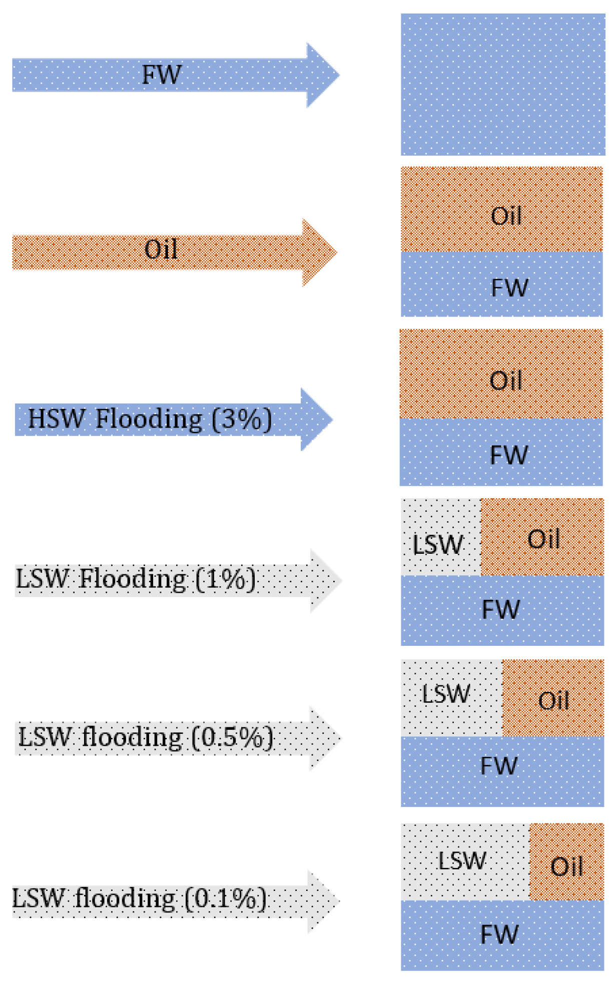
In this paper, the San Saba cylindrical core sample was selected for LSWF studies. Table 3 shows the physical properties of the core sample measured in the lab. In this core flooding laboratory test, the core sample was first saturated with brine by flooding it with FW with a salinity of 3% at a count of 0.2 mL/min. The crude oil used in this experiment had properties close to that of Kashkari oil field, with 7.7 centipoise (cP) viscosity at 20 °C and 3.5 cP at 60 °C. For the purpose of restoring the wettability, the San Saba core was then aged for three weeks at a reservoir temperature of 60 °C. The same flow rate of oil was then restored into the cores. After aging, the core was flooded with FW until residual oil saturation was achieved at a flow rate of 0.2 mL/min (Sorw). The impact of low-salinity brine on oil recovery was then investigated by injecting brines of various salinity, which is explained in Table 4. Figure 2 illustrates the core preparation and four steps of LSWF action.
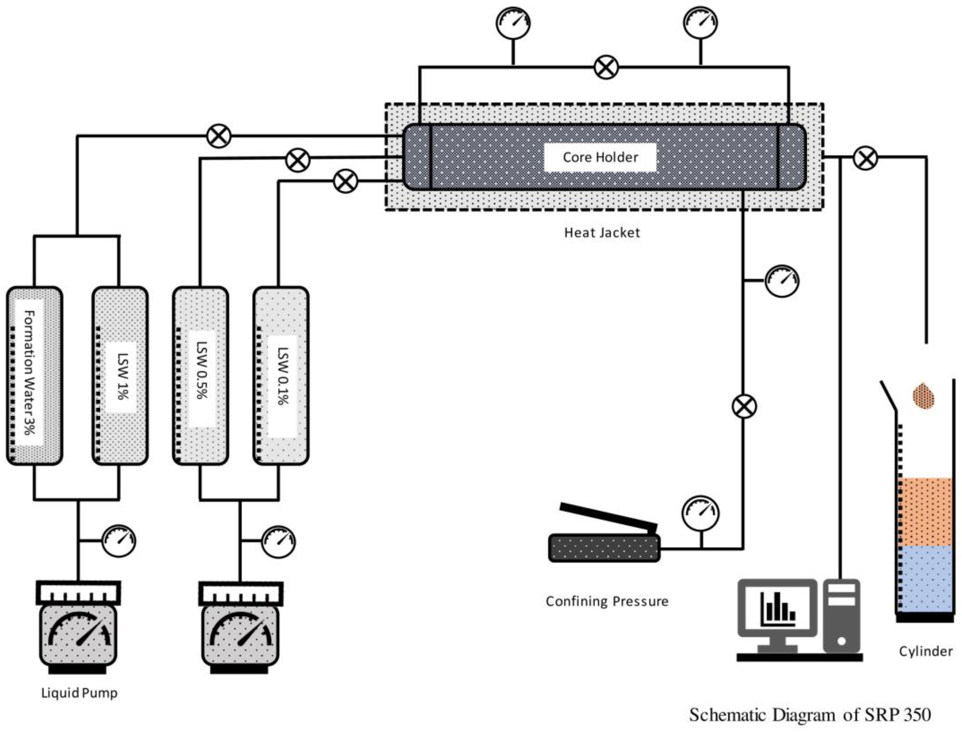
Figure 3 illustrates the SRP-350 apparatus used in the core flooding test. It had accumulators for oil, FW, and LSW.

2.2. Numerical Modeling

Reservoir simulation is a useful approach to confirm and validate laboratory findings and hypotheses under circumstances outside the experimental work’s purview [50]. One of the first models on LSWF reported by Jerauld et al. [25] included salt as an extra component grouped with the aqueous phase. Salinity functions were modeled for comparative permissibility, force over the capillary, dense aqueous phase, and viscidity. Salinity was expected to have a linear relationship with Sorw. Even though the scaling factor of Jerauld et al. [25] is still commonly used in LSWF models, Al-Shalabi et al. [51] emphasized the necessity of employing scaling guidelines for addressing the capillary pressure and relative permeability of oil and water independently.
A thorough model for ion exchange that incorporates geo-chemical processes that take place during LSWF was constructed by Dang et al. [35,52]. The ion exchange model of PHREEQC, two core flooding tests, and heterogeneous Texas sandstone reservoir cores were used to validate the model which was connected with the simulation of composition GEM from CMG. The research studied the possibility of a blend of improved oil recovery process that entailed mixing LSWF. Meanwhile, optimization through well location was assessed using the geochemical model and CO2 injection in a miscible water-alternating-gas process.
Awolayo and Sarma created a geochemical model that incorporated a proportion of comparable divalent cations (Ca2+ and Mg2+) [53]. The model was applied to various carbonate core-flood studies to match historical data. They concluded from the simulation results that better oil recovery at the core scale was dependent on the interaction between mineral dissolution and surface charge modification.
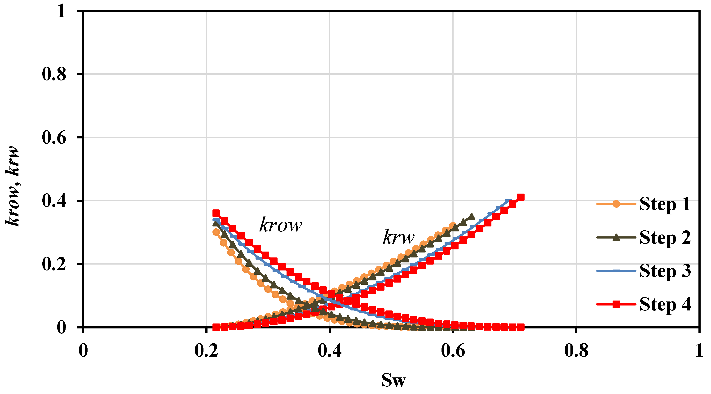
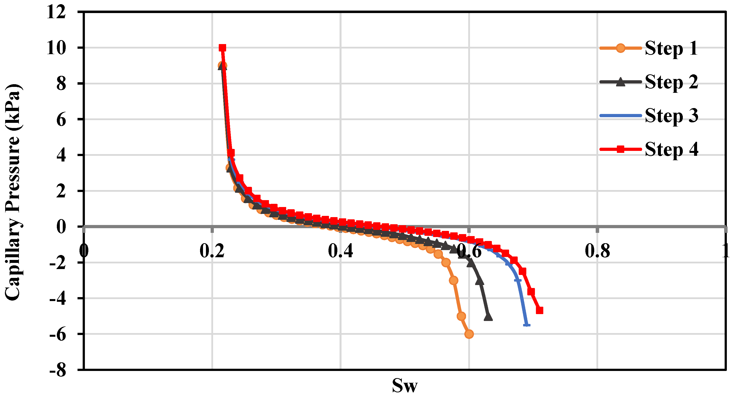
CMG-GEM 2021.10 reservoir simulators were used in this research for modeling the LSWF of the San Saba sandstone core. The petroleum industry extensively uses the GEM simulator packages in CMG as compositional tools with the ability to create reservoir models. To recreate the LSWF laboratory test, a cartesian grille layout with predetermined divisions along the X-axis and the generated model were used [54,55]. Porosity, permeability, and crude oil properties were introduced as input data for reservoir characterization. The GEM tools replicated a cylindrical sandstone core with a volume of 24.95 cm3. A rectangular grid with 40 blocks (each length 0.1267 cm) in the I-direction, a height of 2.5 cm and width of 2.5 cm, was created initially such that its volume was equal to that of the laboratory core. As this model was designed based on the core flooding test model, the grid top was assumed to be 0.01. The porosity, permeability, and other physical properties of the model were designed based on the core sample used in the LSWF test. Figure 4 and Figure 5 demonstrate the differences in Pc, and permeability data were used for LSWF simulation modeling with different salinities.
The composition of injected water was used as the LSWF core test. The mineral reaction, the aqueous reaction, and aqueous component for real perm were set. The initial aqueous composition was set as FW for the first step of LSWF. The initial mineral composition and volume were also assigned as the San Saba core flooding samples, which were closer to the reservoir rock of the Kashkari oil field.
After building the reservoir grid model, the input or output frequency control was set and different variables relevant to the prescribed reservoir model were chosen. Initial oil saturation values were inputted as 70%. It was assumed that no solvent gas was present within the core, or during the recovery test. The injector well was created at the node (1 1 1), whereas the producer well was situated at (40 1 1).
For the LSWF process, the simulated model was flooded based on the laboratory core flooding test. In this process, the simulated model was first saturated by oil, and then the FW was injected for the first step of oil recovery. The FW injection continued until the oil production became constant; then the low-salinity water was injected for the second step, and the same method was continued for the third step. The oil recovery result following low-salinity water injection was compared with the San Saba core laboratory test results. The results were adjusted to reduce the simulation result error as much as possible.

2.3. Kashkari Oil Field Simulation Model

The simulation software used to build the Kashkari oil field simulation model was CMG-GEM. The CMG-GEM in the simulation model of the LSWF lab test section was able to obtain a better match with the laboratory data to simulate the results of the LSWF core test.
Since all the field data were not available to enter into the static model, and only the reports of the Kashkari oil field were available, PETREL software was used to perform petrophysical modeling of the reservoir properties, including porosity and permeability. The characteristics entered into the program were compatible with the reported characteristics and did not exceed the range of real data. It should be noted that in the usual field development plan (FDP) studies of oil fields, the initial static parameters such as physical properties of the oil field (porosity and permeability), system pressure and temperature, fluid distribution, volume coefficient viscosity, relative permeability, and rock and fluid compressibility along the field are performed with the help of petrophysical logs, which are implemented by a petrophysics team and static modeler. However, since all of the data of the petrophysical logs of the wells did not exist, and a static and petrophysical modeling team was not available, petrophysical and geophysical relationships were used to expand the reservoir parameters in the field, and these parameters were expanded.
The relative permeability curves for water and oil for all models (with high and low salinity), which were expressed in the LSWF lab core test simulation sections, were used in this model.
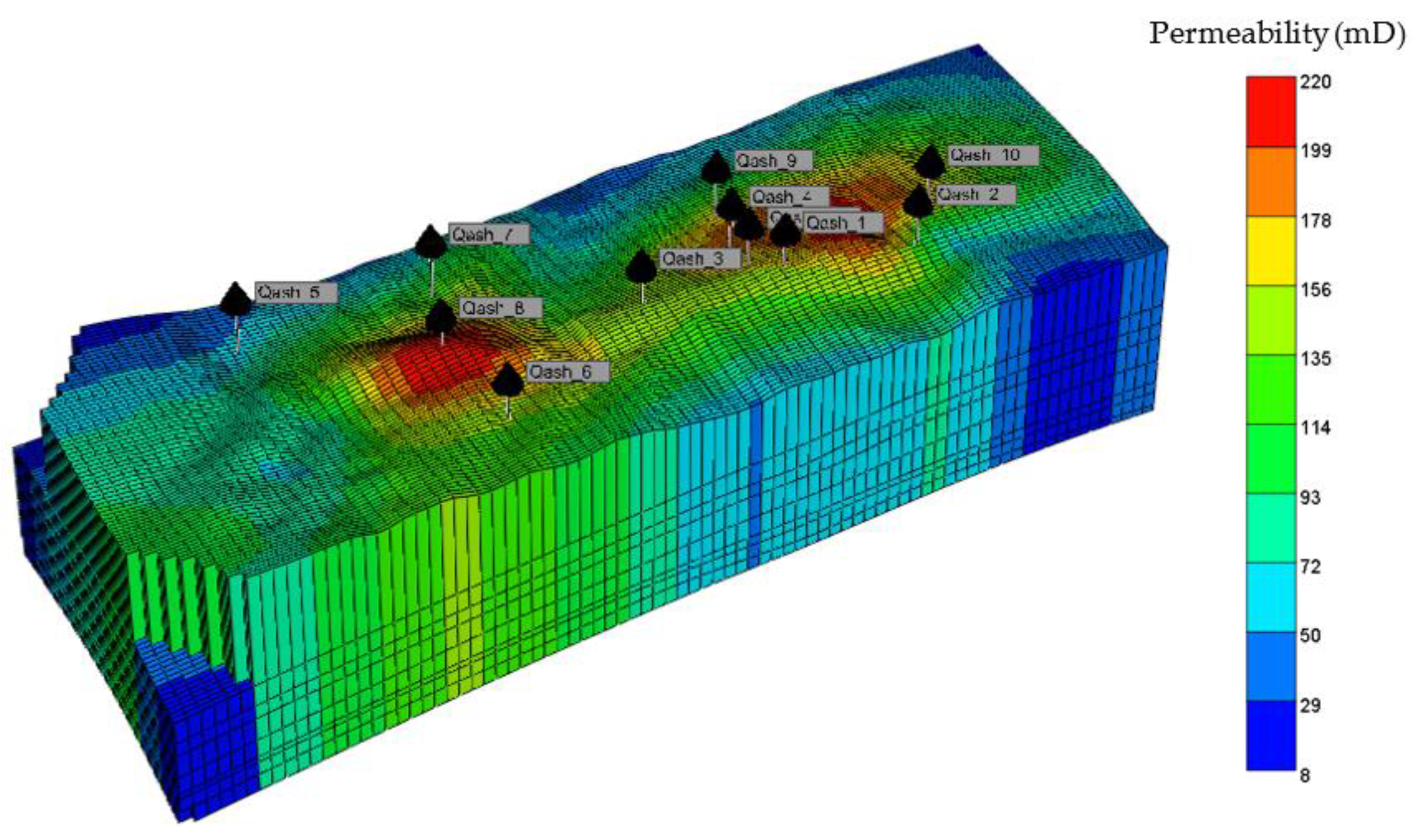
The grid was divided according to the principle of dividing the layers toward the i and j directions, in which the step between each point was 26 m in the i direction and 75 m in the j direction. The vertical direction was divided into 8 layers. The microstructure map of the small sand body thickness in the Kashkari block’s rhythm section was used to control the tectonic fluctuation of the layers. In the simulation model, 76 cells in the x direction, 82 cells in the y direction, and 8 cells in the z direction were considered, which consisted of a total of 49,856 cells (Figure 6). The pressure data were mainly focused on the bottom hole pressure. The production time ranged from 1976 to 2046 with a monthly time step.
It is also necessary to explain that the reservoir model chosen to evaluate the enhancement of oil recovery by LSWF at the field scale was based on a sector of the Kashkari sandstone oil field. This model was used only as an example in this study and is not a recommendation for a real development strategy in this field.

2.4. Application of LSWF in the Kashkari Oil Field

The proposed LSWF in the core flooding experimental section and simulated in CMG-GEM was applied to the Kashkari oil field. Five wells (Qash-1, Qash-3, Qash-4, Qash-9, and Qash-10) were active and used for oil production purposes while the remaining six wells (Qash-2, Qash-5, Qash-6, Qash-7, Qash-8, and Qash-21,) have not yet been activated or did not meet the oil reservoir standards. In this simulation study, three models—the base model with no water injection, FW injection with a salinity of 3%, and LSW injection with a salinity of 0.1%—were designed to evaluate the enhanced oil recovery by LSWF in the Kashkari oil field for a period of 70 years. The details of high-water salinity (3%) and low-salinity water (0.1%) injected in the model were the same as those in steps one and four conducted in the lab test and its simulation model. The oil component was considered the same as in the lab test simulation model. For the base model and FW injection model, the first step relative permeability illustrated in Figure 4 was used, while in the LSW injection model the fourth step relative permeability was used. Wells Qash-2 and Qash-21 were considered as the injection wells. These injection wells had perforated all four reservoirs, XI, XIIa, XIIb, and XIV. It should be noted that the bottom hole pressure (BHP) was considered for well injection and was the same for all three models, and a value of 2900 kPa was set.

3. Results and Discussion

3.1. Experiment and Simulation Results

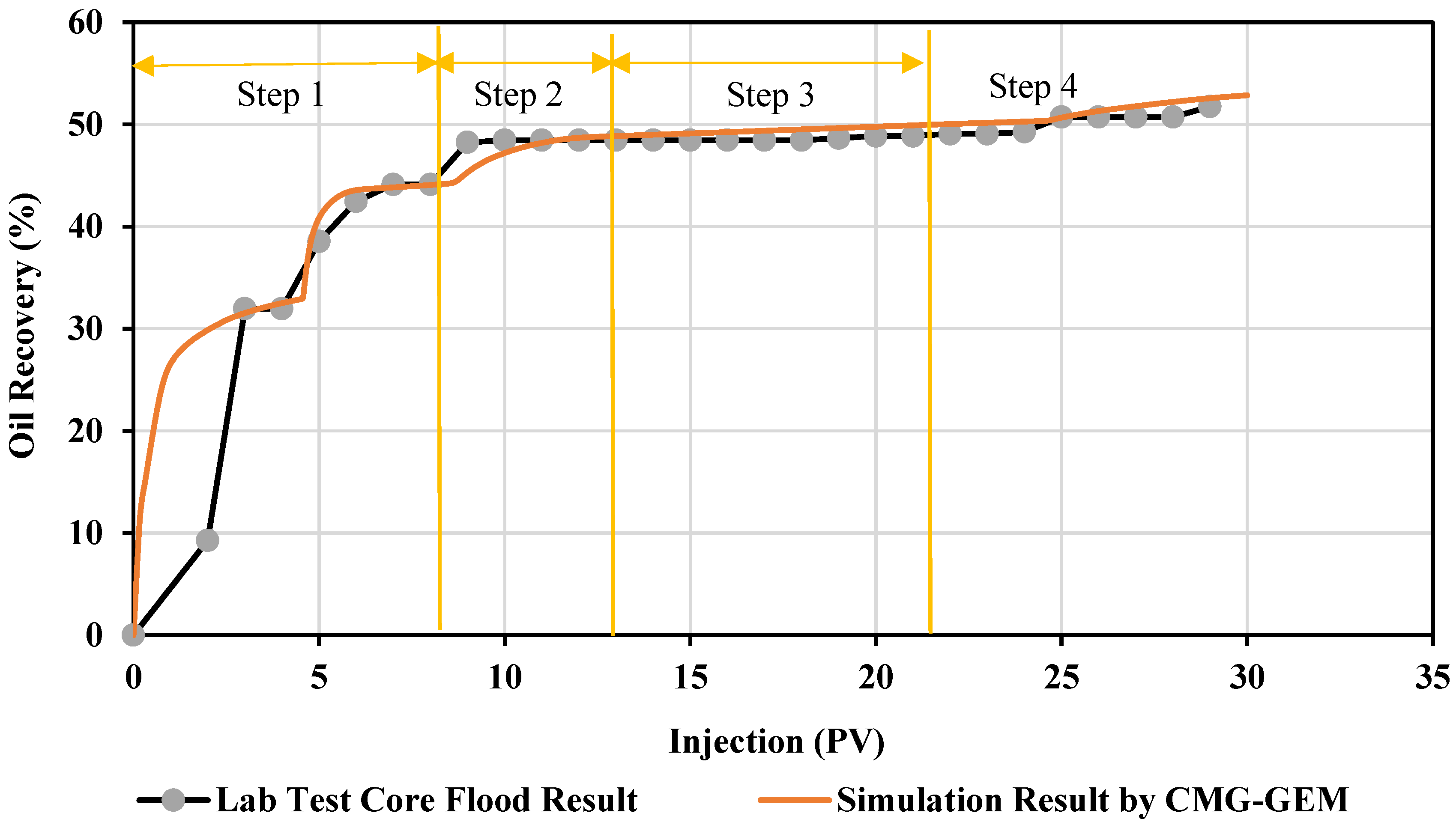
The recovery of oil by LSWF is illustrated in Figure 7, which was conducted based on the four steps core flooding laboratory test result. As shown in Figure 7, in the first step of water flooding, that is, FW with a salinity of 3% injected into the core, the recovery of oil increased rapidly to reach 44%. Then, in the second step of LSWF, in which salinity was 1%, a gradually increasing recovery of oil to reach an additional 4% was achieved. The third step of LSWF, in which the salinity was 0.5%, showed a further 1% oil recovery. By injecting the final step of LSW (salinity of 0.1%), 1.7% more oil recovery resulted. As a result, a total of 51% oil recovery was demonstrated after conducting the four steps of the LSWF laboratory test.
A comparison of the CMG-GEM simulated models of oil recovery by LSWF and the laboratory test is also shown in Figure 7. The oil recovery graph of the simulated model first increased rapidly, the same as the laboratory test result. The oil recovery in the simulation model was 52%, and both laboratory and simulated results were well matched.

3.2. The Application of LSWF to the Kashkari Oil Field Result

Water reduction and oil increment throughout the effective period, average water reduction per day, average oil increment per day, and total oil output for 70 years by natural depletion (base model) were examined to determine the effectiveness of LSWF in the Kashkari oil field.
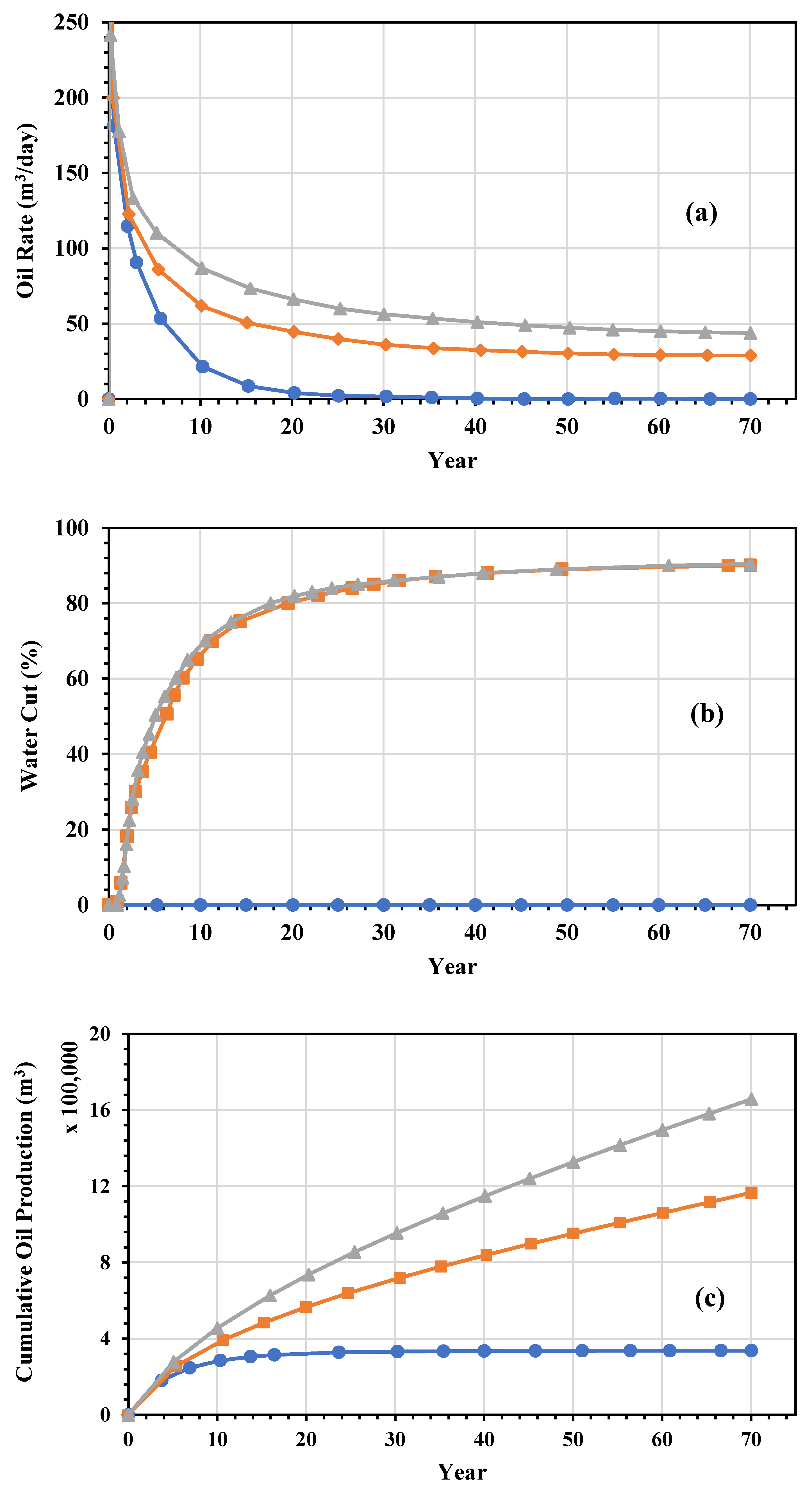
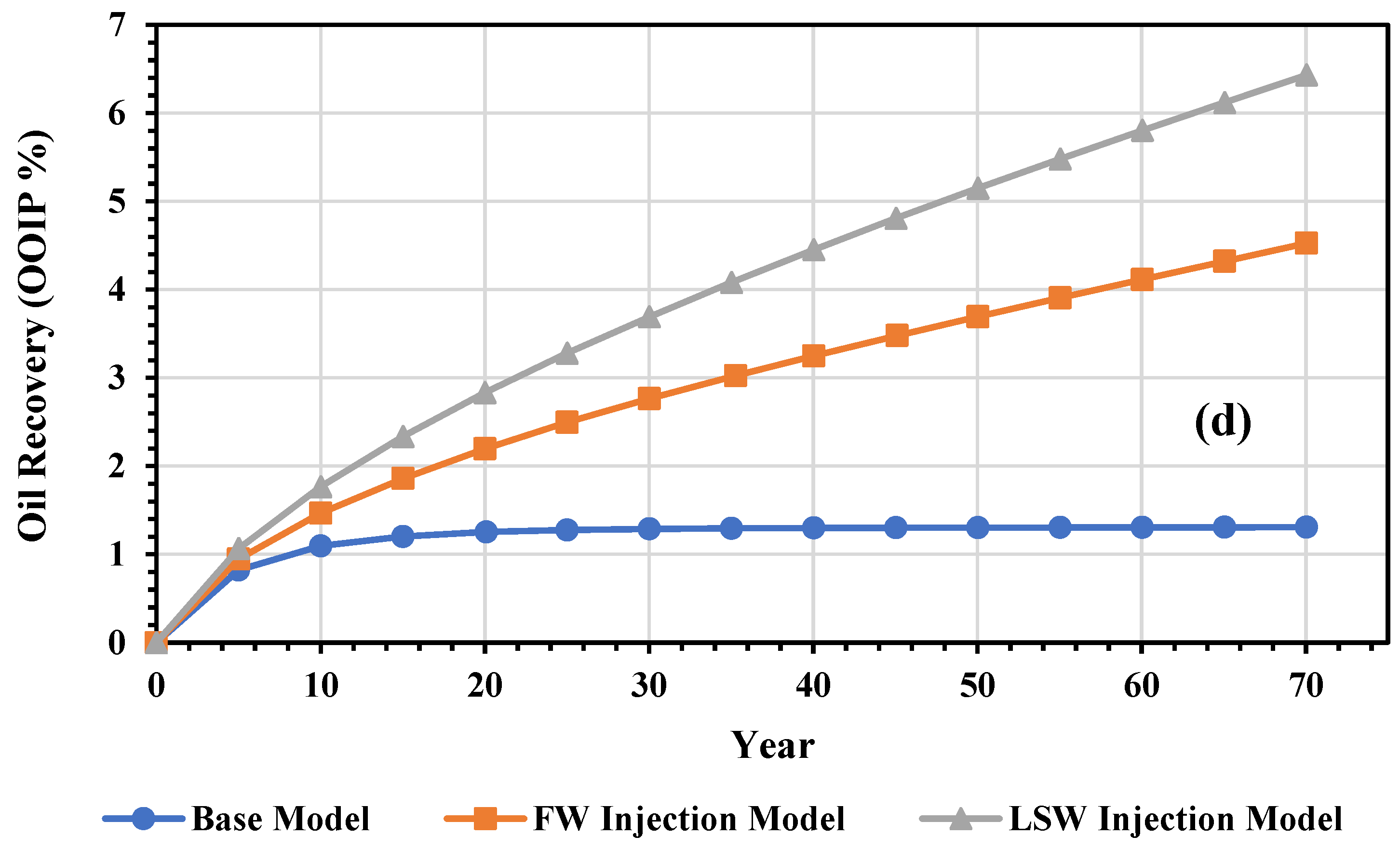
Figure 8 shows the daily oil output, water cut, cumulative oil production, and oil recovery. Figure 8a shows the daily oil production, which started at 200 m3/day and gradually decreased to about 50 m3/day. Figure 8b shows the water cut of the base, FW injection and LSW injection models. Due to non-implementation of water injection in the base model, its water cut was zero, but the water cut in the other two models increased considerably and reached 90%. Figure 8c illustrates the cumulative oil production of the base, FW injection and LSW injection models. In Figure 8c, the cumulative oil production of the base, FW injection and LSW injection models were 2.12, 7.3 and 10.4 MMbbls, respectively. Figure 8d illustrates the oil recovery of the base, FW injection and the LSW injection models. In this figure, the oil recovery of the three afore-mentioned models was 1.3%, 4.5%, and 6.4%, respectively.
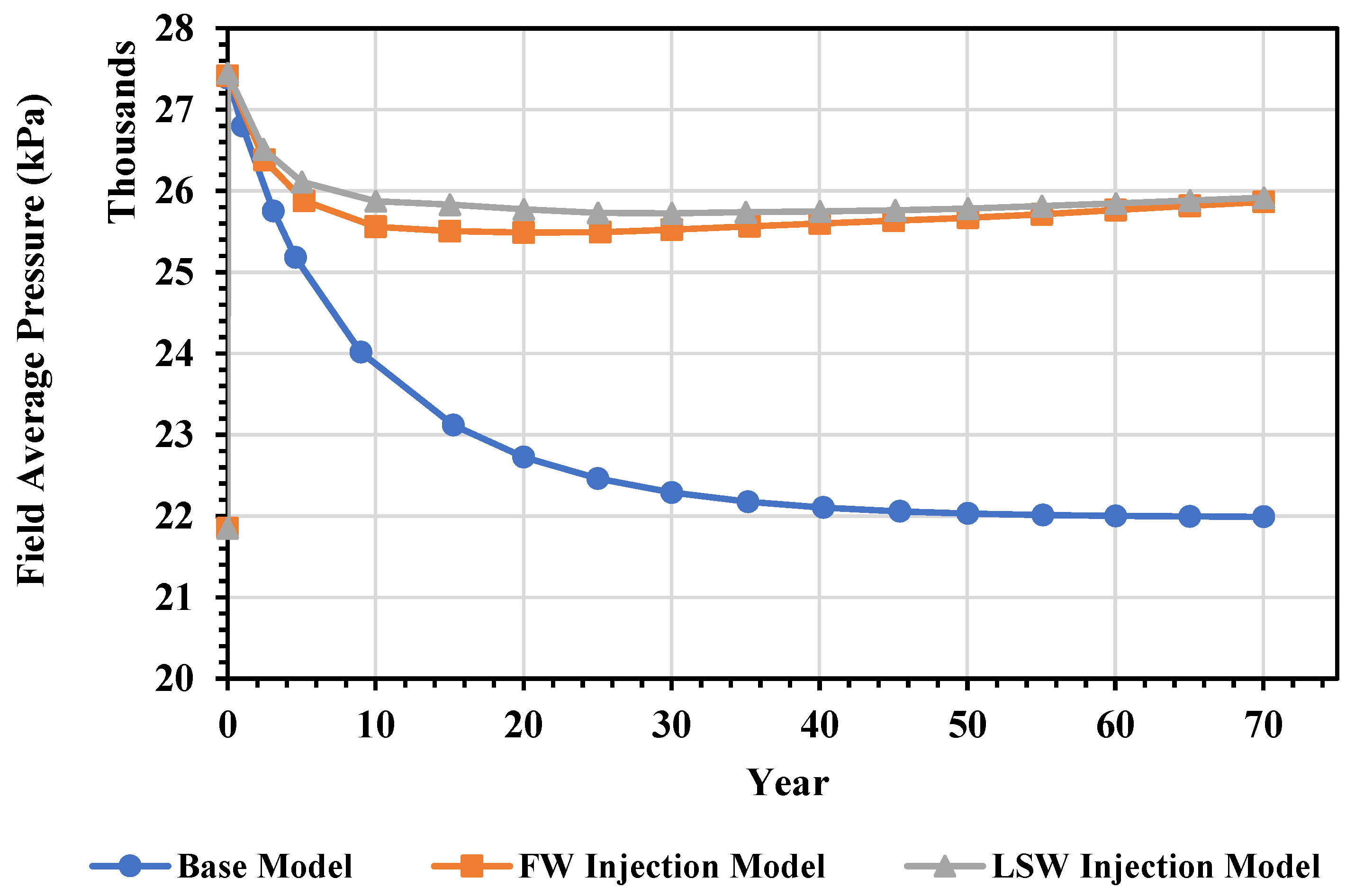
Figure 9 illustrates the Kashkari oil field average pressure for the base, FW injection and LSW injection models, which were designed with 27,000 kPa as the initial condition. It seems from Figure 9 that the pressure of the base, FW injection and LSW injection models gradually decreased from 27,000 kPa, to 22,000 kPa, 25,500 kPa, and 25,700 kPa, respectively.
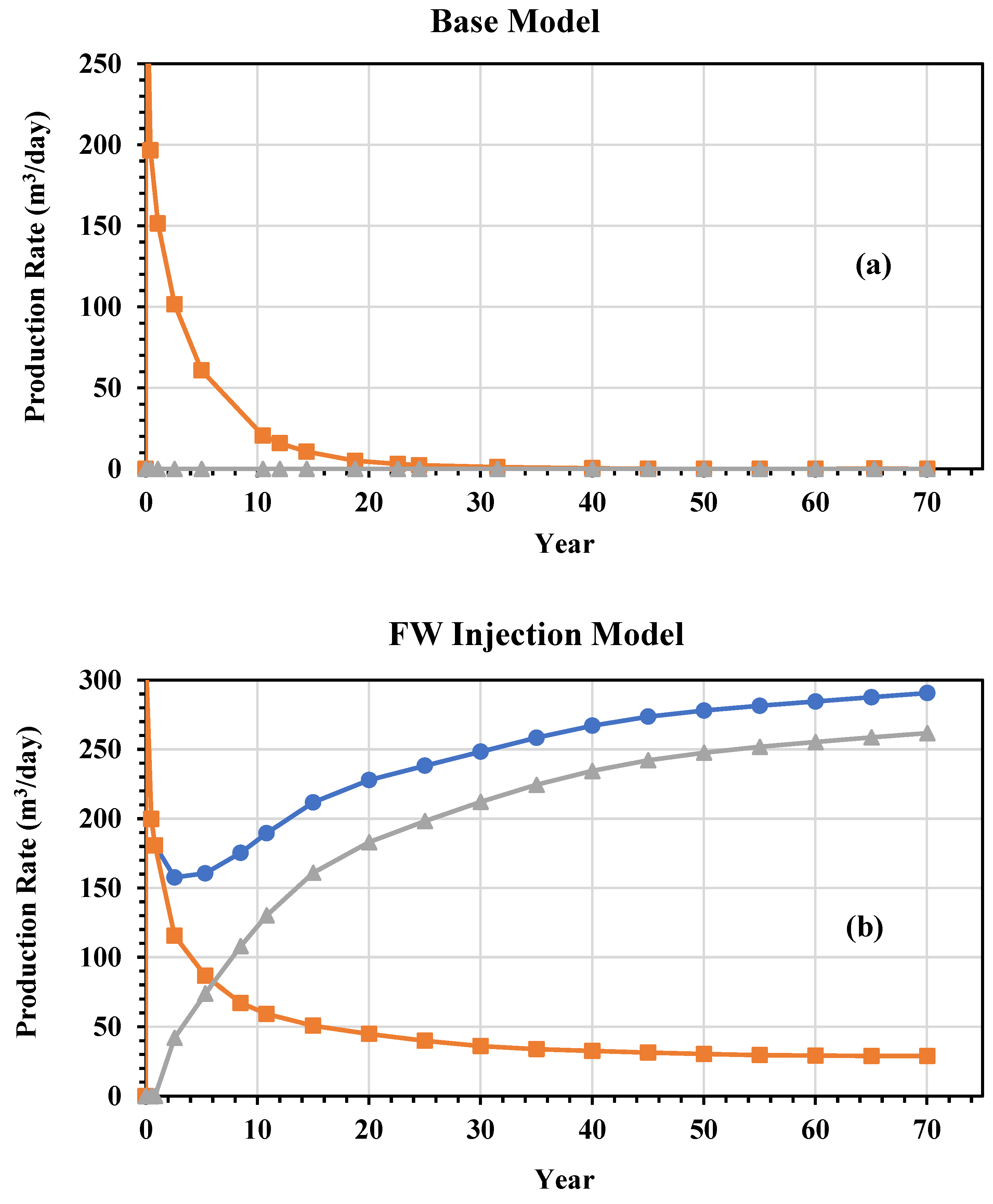
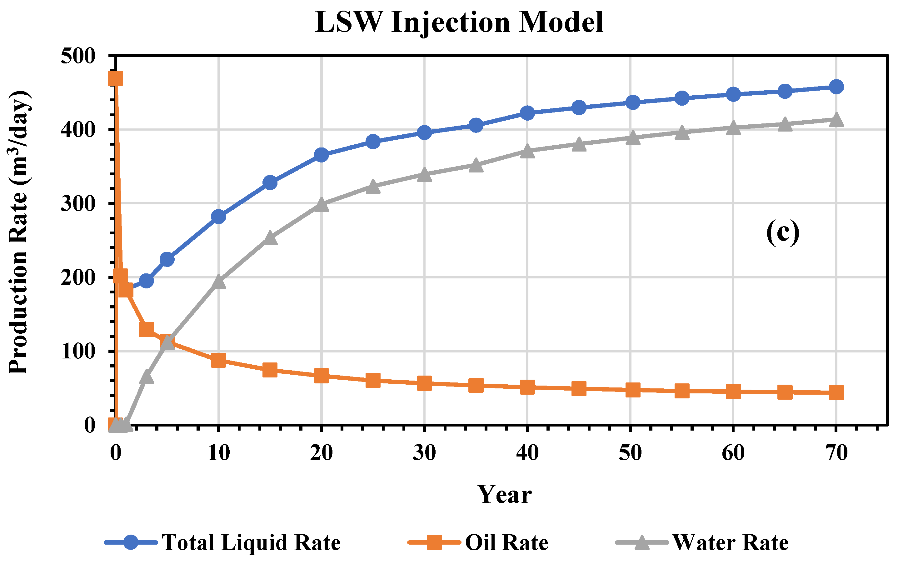
Figure 10 shows the liquid, oil and water production rates of three models (base, FW injection and LSW injection) from the Kashkari oil field. Figure 10a illustrates the liquid, oil and water rates of the base model. In this figure, as water injection was not implemented, the water cut was zero and the oil production decreased considerably. Figure 10b,c illustrate the liquid, oil and water rates of the FW injection and LSW injection models. The figures show that the oil production significantly decreased while the water production increased in these two models.
As seen from Figure 8 and Figure 9, the flow rate of produced oil expressively decreased over time, which is normal. With oil production, and the reduction in the pressure, the oil production capacity of the Kashkari oil field reduced and showed a downward trend. This decrease in oil production rate was greater in the FW injection model with a salinity of 3% than in the LSW injection model with a salinity of 0.1%, which indicates that the injection of water with low salinity is more effective in oil recovery of the Kashkari oil field. In the base model where the injection water was not implemented and was produced by natural pressure, the oil recovery rate was 1.3%. By injecting FW with a salinity of 3%, this amount of recovery increased by 3.2%, but when LSW with a salinity of 0.1% was injected into the oil field, oil recovery showed an increase of 5.1% compared with the base model.
Based on Figure 8, Figure 9 and Figure 10, the ionic changes in the injected water led to the activation of mechanisms for increasing the extraction of the aqueous base, including the change in wettability. In Figure 4, during the activation of the mentioned mechanism, the relative permeability curve of oil increased and the curve of water decreased, or in other words, the movement of water slowed and oil production increased.

4. Conclusions

In this study, the recovery of the Kashkari oil field was evaluated by LSWF through a CMG-GEM simulation model. The process of oil recovery was first studied by a laboratory core flooding experiment to evaluate the efficiency of the LSWF method. Then, a laboratory test simulation model was designed to establish the possibility of applying the technique to the Kashkari oil field. In the last part of this study, the Kashkari oil field simulation model was designed and the LSWF method was applied to it. In the Kashkari oil field simulation model, three models (base, FW injection, and LSW injection) were considered for the evaluation of the effect of LSWF injection on oil recovery. The conclusions of this study are as follows:
(1)
The laboratory core flooding test showed that LSWF (with salinity 1%, 0.5% and 0.1%) can increase oil recovery up to a maximum of 8% after FW injection;
(2)
In CMG-GEM reservoir simulation software, it is possible to simulate intra-phase reactions, ion exchange, and dissolution/precipitation of minerals, and the behavior of ionic liquids can be observed;
(3)
The Kashkari oil field simulation model was established through CMG-GEM reservoir simulation software, and the LSWF (salinity 0.1%) oil recovery method was applied to it. The LSWF application showed a significant effect on the oil recovery of the model;
(4)
The LSW injection results showed a 5.1% increase in oil recovery compared with the base model, and a 1.9% increase compared with the FW injection model;
(5)
The result of LSWF (salinity 0.1%) on the Kashkari oil field shows that this technique can be an effective method for developing the Kashkari oil field.

Author Contributions

Writing—original draft preparation, Z.M.; writing—review and editing, Z.M., K.A. and K.N.S.; software, S.C.; supervision, K.A. and H.F. All authors have read and agreed to the published version of the manuscript.

Funding

This research was funded by JSPS KAKENHI Grant Number JP21K04959.

Institutional Review Board Statement

Not applicable.

Informed Consent Statement

Not applicable.

Data Availability Statement

Not applicable.

Acknowledgments

We would like to express our thanks to Akita University Support for Fostering Research Project, and JSPS KAKENHI grant number JP21K04959 for their valuable funding sources for conducting this research. In addition, the authors would like to express their gratitude to Ahmad Rateb Popal and they are deeply grateful to Watan Oil and Gas Group (WOGL) for permission to have access and use of row data of the Amu Darya basin.

Conflicts of Interest

The authors declare no competing financial interest.

Abbreviations

EoREnhanced oil recovery
MoMPMinistry of Mines and Petroleum
CNPCIChina National Petroleum Corporation International
WOGLOil and Gas Group, Ltd.
CMGComputer Modeling Group
LSWLow-salinity water
LSWFLow-salinity water flooding
PVIPore volume injection
PVPore volume
OFTOil finding technology
STARSTMThermal and Advanced Processes Simulator, software
GEMTMCompositional and Unconventional Simulator, software
SGSSGS Afghanistan Ltd. Oil and Gas Testing Laboratory in Hairatan, Afghanistan
SKUA-GOCADTMGeomodelling software
EMERSONTMAmerican multinational corporation
GEOLOGTMGeomodelling software
RwWater resistivity
SwiIrreducible water saturation
SorwResidual oil saturation
kro max, krw max, krg maxMaximum relative permeability
PcCapillary pressure
PARADIGMTMReservoir model development software
CfFormation rock compressibility
San SabaCore sample from San Saba, Texas
SRP-350Apparatus used for core flooding test
nhAqueous phase hydrocarbon components
naAqueous phase components
nmAqueous mineral components
FWFormation water
mol/kgMoles per kilogram
A γ ,   B γ   and   B ˙ Temperature-dependent coefficients
a ˙ i Ion size parameter
ziValence number of species i
miMolality
rβReaction rate
A ^ β Reactive surface area for mineral β
kβ, Keq,β and Qβ Rate constant
E and k Activation energy for reaction β (J/mol)
RUniversal gas constant (8.314 J/mol-K)
EaActivation energy
A ^ β 0   and   N β 0 Reactive surface area
New porosity
* Reference porosity with no mineral dissolution/precipitation
^ * Porosity with dissolution/precipitation
ρβ Mineral’s molar density
c Rock compressibility
p and p Current and reference pressures
0 Initial porosity
k0 Initial permeability
CECCation exchanger capacity
BHPBottom hole pressure
FDPField development plan
PHREEQCMathematical software
MMbblOne million barrels

References

  1. Fink, J. Petroleum Engineer’s Guide to Oil Field Chemicals and Fluids; Gulf Professional Publishing: Houston, TX, USA, 2021. [Google Scholar]
  2. Bello, A.; Ozoani, J.; Kuriashov, D. Proppant transport in hydraulic fractures by creating a capillary suspension. J. Pet. Sci. Eng. 2022, 208, 109508. [Google Scholar] [CrossRef]
  3. Wu, Z.; Huiqing, L.; Wang, X.; Zhang, Z. Emulsification and improved oil recovery with viscosity reducer during steam injection process for heavy oil. J. Ind. Eng. Chem. 2018, 61, 348–355. [Google Scholar] [CrossRef]
  4. Eftekhari, A.A.; Krastev, R.; Farajzadeh, R. Foam stabilized by fly ash nanoparticles for enhancing oil recovery. Ind. Eng. Chem. Res. 2015, 54, 12482–12491. [Google Scholar] [CrossRef]
  5. Osei-Bonsu, K.; Shokri, N.; Grassia, P. Foam stability in the presence and absence of hydrocarbons: From bubble-to bulk-scale. Colloids Surf. A Physicochem. Eng. Asp. 2015, 481, 514–526. [Google Scholar] [CrossRef]
  6. Dang, C.; Nghiem, L.; Chen, Z.; Nguyen, Q. Modeling low salinity waterflooding: Ion exchange, geochemistry and wettability alteration. In Proceedings of the SPE Annual Technical Conference and Exhibition, New Orleans, LA, USA, 30 September–2 October 2013. [Google Scholar]
  7. Zeinijahromi, A.; Ahmetgareev, V.; Badalyan, A.; Khisamov, R.; Bedrikovetskya, P. Case study of low salinity water injection in Zichebashskoe field. J. Pet. Sci. Res. 2015, 4, 16–31. [Google Scholar] [CrossRef]
  8. Reiter, P.K. A Water-Sensitive Sandstone Flood Using Low Salinity Water; University of Oklahoma: Norman, OK, USA, 1961. [Google Scholar]
  9. Bernard, G.G. Effect of floodwater salinity on recovery of oil from cores containing clays. In Proceedings of the SPE California Regional Meeting, Los Angeles, CA, USA, 26–27 October 1967. [Google Scholar]
  10. Tang, G.; Morrow, N.R. Salinity, temperature, oil composition, and oil recovery by waterflooding. SPE Reserv. Eng. 1997, 12, 269–276. [Google Scholar] [CrossRef]
  11. Purswani, P.; Tawfik, M.S.; Karpyn, Z.T. Factors and mechanisms governing wettability alteration by chemically tuned waterflooding: A review. Energy Fuels 2017, 31, 7734–7745. [Google Scholar] [CrossRef]
  12. Jadhunandan, P.; Morrow, N.R. Effect of wettability on waterflood recovery for crude-oil/brine/rock systems. SPE Reserv. Eng. 1995, 10, 40–46. [Google Scholar] [CrossRef]
  13. Yildiz, H.O.; Morrow, N.R. Effect of brine composition on recovery of Moutray crude oil by waterflooding. J. Pet. Sci. Eng. 1996, 14, 159–168. [Google Scholar] [CrossRef]
  14. Austad, T.; Strand, S.; Madland, M.V.; Puntervold, T.; Korsnes, R.I. Seawater in chalk: An EOR and compaction fluid. SPE Reserv. Eval. Eng. 2008, 11, 648–654. [Google Scholar] [CrossRef]
  15. Austad, T.; Shariatpanahi, S.; Strand, S.; Black, C.; Webb, K. Conditions for a low-salinity enhanced oil recovery (EOR) effect in carbonate oil reservoirs. Energy Fuels 2012, 26, 569–575. [Google Scholar] [CrossRef]
  16. Fathi, S.J.; Austad, T.; Strand, S. “Smart water” as a wettability modifier in chalk: The effect of salinity and ionic composition. Energy Fuels 2010, 24, 2514–2519. [Google Scholar] [CrossRef] [Green Version]
  17. Zhang, P.; Tweheyo, M.T.; Austad, T. Wettability alteration and improved oil recovery in chalk: The effect of calcium in the presence of sulfate. Energy Fuels 2006, 20, 2056–2062. [Google Scholar] [CrossRef]
  18. Qiao, C.; Li, L.; Johns, R.T.; Xu, J. A mechanistic model for wettability alteration by chemically tuned waterflooding in carbonate reservoirs. SPE J. 2015, 20, 767–783. [Google Scholar] [CrossRef] [Green Version]
  19. Qiao, C.; Johns, R.; Li, L. Modeling low-salinity waterflooding in chalk and limestone reservoirs. Energy Fuels 2016, 30, 884–895. [Google Scholar] [CrossRef]
  20. Bader, M. Seawater versus produced water in oil-fields water injection operations. Desalination 2007, 208, 159–168. [Google Scholar] [CrossRef]
  21. Puntervold, T.; Strand, S.; Austad, T. New method to prepare outcrop chalk cores for wettability and oil recovery studies at low initial water saturation. Energy Fuels 2007, 21, 3425–3430. [Google Scholar] [CrossRef]
  22. Shariatpanahi, S.F.; Strand, S.; Austad, T. Evaluation of water-based enhanced oil recovery (EOR) by wettability alteration in a low-permeable fractured limestone oil reservoir. Energy Fuels 2010, 24, 5997–6008. [Google Scholar] [CrossRef]
  23. Strand, S.; Austad, T.; Puntervold, T.; Høgnesen, E.J.; Olsen, M.; Barstad, S.M.F. “Smart water” for oil recovery from fractured limestone: A preliminary study. Energy Fuels 2008, 22, 3126–3133. [Google Scholar] [CrossRef] [Green Version]
  24. Zhang, Y.; Xie, X.; Morrow, N.R. Waterflood performance by injection of brine with different salinity for reservoir cores. In Proceedings of the SPE Annual Technical Conference and Exhibition, Anaheim, CA, USA, 11–14 November 2007. [Google Scholar]
  25. Jerauld, G.R.; Lin, C.; Webb, K.J.; Seccombe, J.C. Modeling low-salinity waterflooding. SPE Reserv. Eval. Eng. 2008, 11, 1000–1012. [Google Scholar] [CrossRef]
  26. Zhang, P.; Tweheyo, M.T.; Austad, T. Wettability alteration and improved oil recovery by spontaneous imbibition of seawater into chalk: Impact of the potential determining ions Ca2+, Mg2+, and SO42−. Colloids Surf. A Physicochem. Eng. Asp. 2007, 301, 199–208. [Google Scholar] [CrossRef]
  27. Webb, K.; Black, C.; Edmonds, I. Low salinity oil recovery–The role of reservoir condition corefloods. In Proceedings of the IOR 2005-13th European Symposium on Improved Oil Recovery, Budapest, Hungary, 25–27 April 2005; p. cp-12-00045. [Google Scholar]
  28. Morrow, N.R.; Tang, G.-q.; Valat, M.; Xie, X. Prospects of improved oil recovery related to wettability and brine composition. J. Pet. Sci. Eng. 1998, 20, 267–276. [Google Scholar] [CrossRef]
  29. Webb, K.; Black, C.a.; Al-Ajeel, H. Low salinity oil recovery-log-inject-log. In Proceedings of the SPE/DOE Symposium on Improved Oil Recovery, Tulsa, OK, USA, 17–21 April 2004. [Google Scholar]
  30. McGuire, P.; Chatham, J.; Paskvan, F.; Sommer, D.; Carini, F. Low salinity oil recovery: An exciting new EOR opportunity for Alaska’s North Slope. In Proceedings of the SPE Western Regional Meeting, Irvine, CA, USA, 30 March–1 April 2005. [Google Scholar]
  31. Lager, A.; Webb, K.J.; Collins, I.R.; Richmond, D.M. LoSal enhanced oil recovery: Evidence of enhanced oil recovery at the reservoir scale. In Proceedings of the SPE Symposium on Improved Oil Recovery, Tulsa, OK, USA, 20–23 April 2008. [Google Scholar]
  32. Skrettingland, K.; Holt, T.; Tweheyo, M.T.; Skjevrak, I. Snorre low-salinity-water injection—Coreflooding experiments and single-well field pilot. SPE Reserv. Eval. Eng. 2011, 14, 182–192. [Google Scholar] [CrossRef]
  33. Austad, T.; Strand, S.; Høgnesen, E.; Zhang, P. Seawater as IOR fluid in fractured chalk. In Proceedings of the SPE International Symposium on Oilfield Chemistry, The Woodlands, TX, USA, 2–4 February 2005. [Google Scholar]
  34. Hognesen, E.J.; Strand, S.; Austad, T. Waterflooding of preferential oil-wet carbonates: Oil recovery related to reservoir temperature and brine composition. In Proceedings of the SPE Europec/EAGE Annual Conference, Madrid, Spain, 13–16 June 2005. [Google Scholar]
  35. Dang, C.; Nghiem, L.; Nguyen, N.; Chen, Z.; Nguyen, Q. Mechanistic modeling of low salinity water flooding. J. Pet. Sci. Eng. 2016, 146, 191–209. [Google Scholar] [CrossRef]
  36. Mehrad, A.T.; Zvolinski, V.; Kapralova, D.; Niazmand, M.A. Assessment of oil and gas resources of northern Afghanistan and their impact on energy security in the country. In Proceedings of the IOP Conference Series: Materials Science and Engineering, Moscow, Russia, 16–17 April 2020; p. 012038. [Google Scholar]
  37. Watan Oil and Gas Group. Formation Evaluation & Geomodeling—Study, Kashkari Field, Afghanistan; Watan Oil and Gas Group: Dubai, United Arab Emirates, 2017; p. 91. [Google Scholar]
  38. Kashkari Oilfield Development Plan (1st Phase); Kabul, Afghanistan, 2013; p. 140.
  39. Sabawon, A.; Kurihara, M.; Waseda, A.; Nishita, H.; Okumura, F.; Nakashima, H. Estimation of petroleum source rocks based on the crude oil geochemistr y in Amu Darya Basin, northern Afghanistan. J. Jpn. Assoc. Pet. Technol. 2016, 81, 230–242. [Google Scholar] [CrossRef] [Green Version]
  40. Gas, W.G.O. Kashkari Field, Afghanistan 2017 Field Development Plan; Sarotaga Technology: Dubai, United Arab Emirates, 2017; p. 183. [Google Scholar]
  41. Geophysical, P. Formation Evaluation & Geomodeling—Study, Kashkari Field, Afghanistan.; Emerson, Paradigm Geophysical: Dubai, United Arab Emirates, 2017; p. 91. [Google Scholar]
  42. Promotion of Oil and Gas Producing Areas to the Private Sector, Executive Summery; Gustavson Associates: Boulder, CO, USA, 2005; p. 221.
  43. Kashkari Oilfield. Well No.: Kash-1, Geological Design for Workover; CNPCI Watan Oil and Gas Afghanistan Ltd.: Beijing, China, 2012; p. 29. [Google Scholar]
  44. Kashkari Oilfield. Well No.: Kash-3, Geological Design for Workover; CNPCI WATAN Oil and Gas Afghanistan Ltd.: Beijing, China, 2012; p. 30. [Google Scholar]
  45. Kashkari Oilfield. Well No.: Kash-4, Geological Design for Workover; CNPCI WATAN Oil and Gas Afghanistan Ltd.: Beijing, China, 2012; p. 31. [Google Scholar]
  46. Kashkari Oilfield. Well No.: Kash-9, Geological Design for Workover; CNPCI WATAN Oil and Gas Afghanistan Ltd.: Beijing, China, 2012; p. 29. [Google Scholar]
  47. Kashkari Oilfield. Well No.: Kash-10, Geological Design for Workover; CNPCI WATAN Oil and Gas Afghanistan Ltd.: Beijing, China, 2012; p. 28. [Google Scholar]
  48. Kashkari Oilfield. Well No.: Kash-21, Geological Design for Workover; CNPCI WATAN Oil and Gas Afghanistan Ltd.: Beijing, China, 2012; p. 7. [Google Scholar]
  49. Russian Production Report; State Institute on Design and Research in Oil Industry: USSR Ministry of Oil Industry: Moscow, Russia, 1980.
  50. Derkani, M.H.; Fletcher, A.J.; Abdallah, W.; Sauerer, B.; Anderson, J.; Zhang, Z.J. Low salinity waterflooding in carbonate reservoirs: Review of interfacial mechanisms. Colloids Interfaces 2018, 2, 20. [Google Scholar] [CrossRef] [Green Version]
  51. Al-Shalabi, E.W.; Sepehrnoori, K.; Delshad, M. Does the double layer expansion mechanism contribute to the LSWI effect on hydrocarbon recovery from carbonate rocks? In Proceedings of the SPE Reservoir Characterization and Simulation Conference and Exhibition, Abu Dhabi, United Arab Emirates, 16–18 September 2013. [Google Scholar]
  52. Dang, C.; Nghiem, L.; Nguyen, N.; Chen, Z.; Nguyen, Q. Modeling and optimization of low salinity waterflood. In Proceedings of the SPE Reservoir Simulation Symposium, Houston, TX, USA, 23–25 February 2015. [Google Scholar]
  53. Awolayo, A.N.; Sarma, H.K.; Nghiem, L.X. A comprehensive geochemical-based approach at modeling and interpreting brine dilution in carbonate reservoirs. In Proceedings of the SPE Reservoir Simulation Conference, Montgomery, TX, USA, 20–22 February 2017. [Google Scholar]
  54. Tunnish, A.; Shirif, E.; Henni, A. History matching of experimental and CMG-STARS results. J. Pet. Explor. Prod. Technol. 2019, 9, 341–351. [Google Scholar] [CrossRef]
  55. Computer Modelling Group Ltd. CMG—GEM Technical Manual; T2L 2M1; Computer Modelling Group Ltd.: Calgary, Canada, 2021. [Google Scholar]
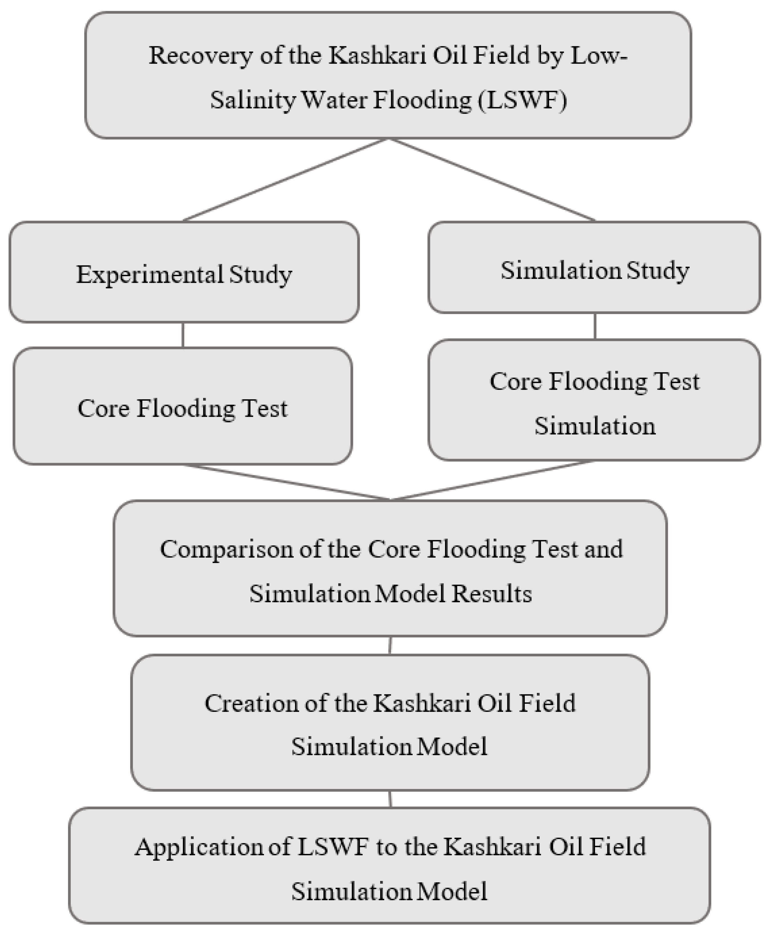
Figure 1. Diagram of Kashkari oil field recovery by LSWF.
Energies 16 00534 g001
Figure 2. Core preparation and four steps of LSWF action. The LSWF core test was conducted at a condition of 60 °C which was the same as the Kashkari oil field temperature, along with the confining pressure of 20,684 kPa and a flow count of 0.2 mL/min.
Energies 16 00534 g002
Figure 3. SRP-350 apparatus used for the core flooding test.
Energies 16 00534 g003
Figure 4. Relative permeability curves were used for LSWF simulation modeling with different salinities; step 1 is the formation water injection with a salinity of 3%, steps 2, 3, and 4 are with salinities of 1%, 0.5%, and 0.1%, respectively.
Energies 16 00534 g004
Figure 5. Capillary pressure curves used for LSWF simulation model with different salinities; step 1 is the formation water injection with a salinity of 3%, steps 2, 3, and 4 are with salinities of 1%, 0.5%, and 0.1%, respectively.
Energies 16 00534 g005
Figure 6. Kashkari oil field 3D model showing distribution of permeability.
Energies 16 00534 g006
Figure 7. Laboratory and simulation results of different salinity water injections, step 1 is formation water with a salinity of 3%; step 2 with a salinity of 1%; step 3 with a salinity of 0.5%; and step 4 with a salinity of 0.1%.
Energies 16 00534 g007
Figure 8. The influence of LSW injection on (a) oil rate daily production, (b) water cut, (c) cumulative water production, and (d) oil recovery in three models: the base model (the injection water is not implemented and is produced by natural pressure), formation water injection model, and LSW (with a salinity of 0.1%) injection model of the Kashkari oil field.
Energies 16 00534 g008aEnergies 16 00534 g008b
Figure 9. The average pressure evaluation of the base, FW injection, and LSW injection models of the Kashkari oil field.
Energies 16 00534 g009
Figure 10. The liquid, oil and water rates of the (a) base, (b) FW injection, and (c) LSW injection models.
Energies 16 00534 g010aEnergies 16 00534 g010b
Table 1. Kashkari oil field FW salinity.
Salinity
Type(g/L)
Na2SO433–39
Na2SO426–35
NaHCO311–16
Ion Contents (mg/L)
ClSO42−HCO3−Ca2+Mg2+K + and Na+
12,456.34172.82091.6402.575.510,321.3
Table 2. Pressure and viscosity of Kashkari oil field crude oil at standard temperature.
ZonePressure (kPa)Viscosity (cp)
XIa6398.02.1
XIIa4212.92.19
XIIb4398.03.4
XIV2978.17.6
Table 3. Core sample physical properties.
Core IDSandstone
Core typeSan Saba sandstone
Core diameter (mm)25.14
Core length (mm)50.63
Core weight (g)52.13
Gas permeability (mD)63.68
Pore volume (cc)5.44
Bulk volume (cc)25.13
Porosity (%)21.6
Water permeability (mD)25
Table 4. FW ion contents.
Ion Contents (PPM)ClSO42−HCO3−Ca2+Mg2+Na+Total
FW (3%)12,488417220914027510,27829,506
LSW (1%)416213906971342534269834
LSW (0.5%)2081695348671217134916
LSW (0.1%)41613969132343982
Disclaimer/Publisher’s Note: The statements, opinions and data contained in all publications are solely those of the individual author(s) and contributor(s) and not of MDPI and/or the editor(s). MDPI and/or the editor(s) disclaim responsibility for any injury to people or property resulting from any ideas, methods, instructions or products referred to in the content.