1. Introduction
The transport sector, as expressed by different studies [
1], is one of the main reasons for global warming caused by the increase in CO
2 emission. In 1997, several countries have committed themselves through the Kyoto Protocol [
2] to reduce greenhouse emissions to admissible values. The Paris climate agreement [
3] has been signed in 2015 to reduce the global temperature increase up to 2 °C. Moreover, in recent years the legislation regarding pollutant emission for vehicle homologation [
4] has become increasingly stringent and binding, forcing manufacturers to find innovative solutions. In this perspective, ultra-lean combustion, low-temperature combustion (LTC) modes, and carbon-free fuels have emerged as possible options able to comply with these tough tasks. Homogeneous charge compression ignition (HCCI) [
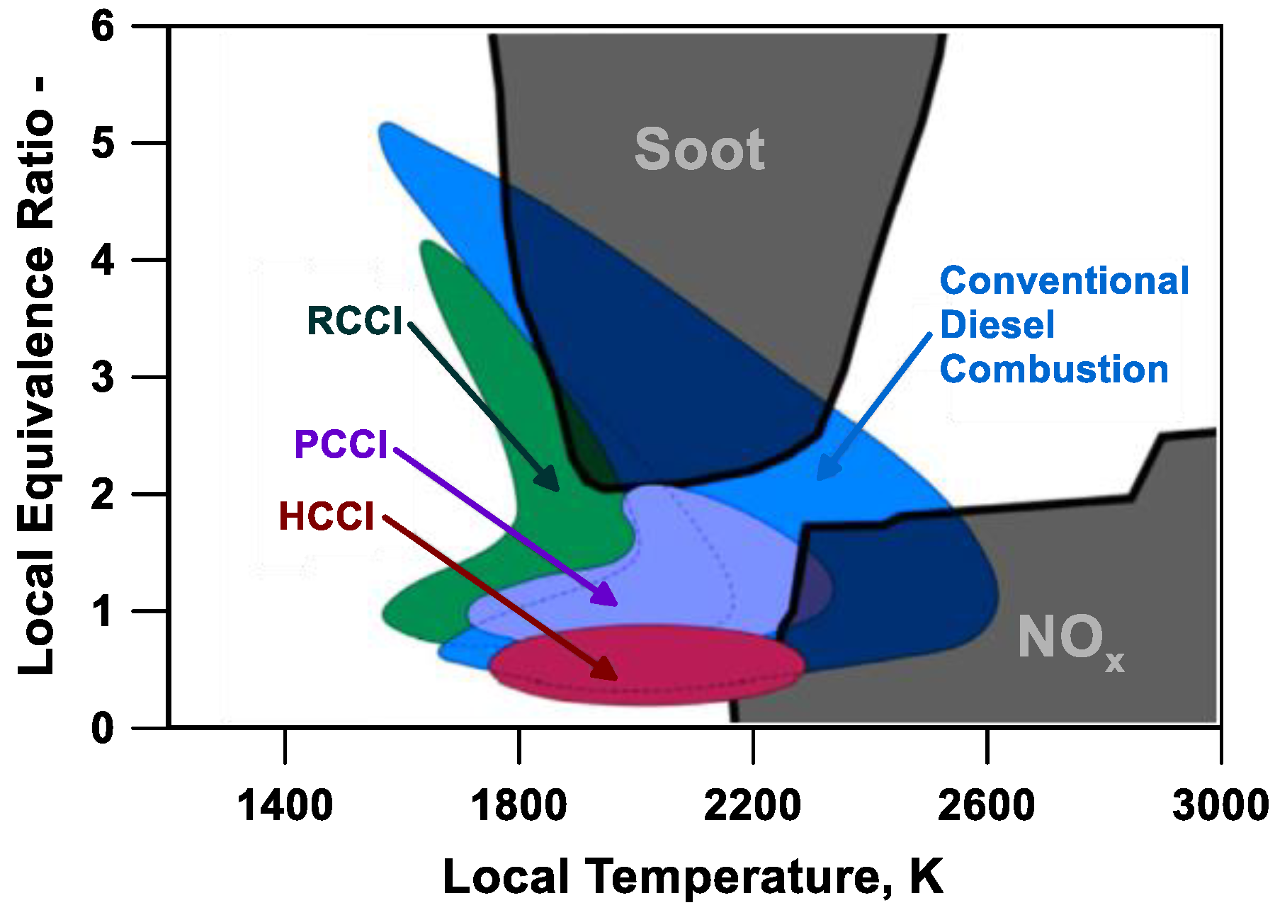
5] is a promising LTC mode (
Figure 1), capable of both reducing the nitrogen oxides (NOx) and obtaining globally higher thermal efficiencies than spark ignition (SI) engines.
HCCI engines exhibit a homogeneous and highly diluted mixture, which auto-ignites due to the high levels of pressure and temperature caused by piston compression. The auto-ignition process is controlled by chemical kinetics, which is strongly dependent on the local temperature in the combustion chamber. Experimental and numerical analyses [
6,
7,
8,
9,
10] showed a temperature stratification peculiar to HCCI engines. The auto-ignition of the charge portion having the highest temperature promotes and controls the development of the combustion through the entire combustion chamber, hence determining the heat release evolution.
On the upside, the HCCI engines do not figure a direct control of the combustion onset in contrast to the SI engines, controlled by the spark event, or to the reactivity controlled compression ignition (RCCI), monitored by the charge stratification (
Figure 1). RCCI engines on one side exhibit high thermal efficiencies, but on the other side present some difficult challenges [
11,
12] such as relevant in-cylinder pressure rise rate, excessive emissions of unburned hydrocarbons (uHCs) and carbon monoxide (CO) at the exhaust, possible misfiring, and cold start problems.
The absence of direct control of the ignition process in HCCI mode limits the operating range of the engine, whose load is usually constrained to avoid excessive pressure rise rate and the damaging to engine components [
14]. Charge dilution with excess air and recirculated exhaust gas helps in mitigating the above drawbacks, also contributing to reducing the production of NOx. On the other side, this solution may cause larger productions of uHC and CO because of the slower combustion speeds.
Numerical simulations, such as 0D and 3D-CFD models, can be appropriate tools to reproduce the unconventional combustion phenomenon, as deeply investigated by the authors in their past works [
15,
16,
17], thus, supporting also the development of HCCI engines. In this regard, the main tasks of the numerical models are the deployment of optimal combustion control strategies, engine calibration, and engine design.
In 3D CFD models, the HCCI engines are described as homogeneous reactors, in which turbulence is not usually considered [
18,
19,
20]. The combustion chamber is divided into a defined number of control volumes, in each of which the conservation equations of mass, energy, and momentum are solved, together with chemistry evolution. Quasi-dimensional models are suitable tools to interpret the combustion phenomenon in HCCI engines. These models are able to combine high predictivity with reduced effort compared to 3D ones. Since the HCCI ignition is driven by chemical kinetics, the resolution of appropriate chemical kinetics mechanisms is required in the cylinder, depending on the fuel properties [
21,
22,
23]. Particularly, multi-zone phenomenological models are capable to capture the impact of the characteristic in-cylinder thermal stratification and the evolution of chemical kinetics of HCCI engines, leading to an accurate reproduction of the ignition process of the mixture across the combustion chamber [
23,
24].
Multi-zone models schematize the cylinder volume in a fixed number of zones, whose number is chosen as a trade-off between prediction accuracy and computational effort. In the literature, several multi-zone approaches have been proposed. Kodavasal et al. [
25] define two main types of multi-zone models, classified as balloon-type multi-zone models and onion-skin multi-zone models. In [
25] a balloon-type multi-zone model is presented, in which each zone loses a determined fraction of heat through the cylinder walls. The unevenness of the zonal wall heat losses generates a thermal stratification during the compression stroke.
Fathi et al. [
26] developed a multi-zone model where only heat exchange among zones is described. For the evaluation of the mixture’s chemical evolution, a detailed kinetic scheme is used. Bissoli et al. [
27] developed an onion-skin model, where mass and heat exchange among zones are considered. The approach adapts from the 3D CFD simulations sub-model for heat transfer and turbulence. A detailed kinetic scheme is used to evaluate the auto-ignition of the mixture. Nazoktabar et al. [
28] also developed a multi-zone model coupled with a detailed chemical kinetic scheme to compute the auto-ignition of the mixture inside the combustion chamber. This model is then used to create a grey-box model to predict the performance and emission parameters in transient conditions.
In the multi-zone approaches above mentioned, the computational burden rapidly grows with the number of zones as the chemical kinetics has to be solved in each region of the combustion chamber. To overcome this issue, the so-called tabulated kinetics of ignition (TKI) approach represents a reliable tool to retain high accuracy with a strong reduction of the computational effort. Preliminary chemical kinetics calculations are solved in a constant-volume or constant-pressure homogeneous reactor at different initial conditions of pressure, temperature, equivalence ratio (
Φ =
ast/
a), and residual content (
xr). In the second stage, the main outputs of the chemical kinetics simulation, such as the combustion progress variable and ignition delay time are collected in a database, which is then used during the runtime simulations of the engine [
29].
In this work, a multi-zone model coupled with the TKI approach able to describe both the combustion process, performance, and noxious emission of the HCCI engines is developed and extensively validated. The work is focused on the numerical analysis of four different HCCI engines using different fuels, namely hydrogen, methane, n-heptane, and a mixture of n-heptane, toluene, and ethanol, in which the proportion of the fuel components can be varied. To demonstrate the reliability of the proposed model, the analyses have been carried out for different equivalence ratios (Φ), exhaust gas recirculation (EGR) rates, intake pressure and temperature, and fuel blending.
The presented study aims to overcome the typical trade-off between spatial resolution of the multi-zone schematization and the number of species/reactions of the chemical kinetic scheme used to describe the HCCI combustion thanks to the adoption of the TKI approach. As shown in the following, this methodology allows estimating chemistry evolution with suitable accuracy and limited computational time, allowing to increase the number of zones in which the cylinder is subdivided. This permits not compromising the typical computational efficiency of 0D /1D codes and also having an appropriate spatial resolution needed to describe pollutant formation, which is highly affected by local composition and gas state.
From an extensive study of the available works, it was possible to find out that while multi-zone models to describe HCCI combustion have been widely presented and developed for many years in the scientific literature, the simulation of pollutant emissions of HCCI engines is still poorly explored in a 0D framework. Predicted emissions in a limited number of engine operating points are shown in [
28]. In none of the literature works, extensive validation of pollutant emissions produced by HCCI engines has been found. This literature gap is addressed in the presented article, where sub-models of NOx and uHC emissions production are verified for different engines, fuels, and operating conditions.
The manuscript is organized as briefly summarized in the following. In the first part, a description of the main characteristics of the fuel is provided and the engines are selected. Subsequently, the methodology coupled with the mathematical formulation of the model is presented. Then, the TKI solution is implemented in commercial software and then is validated with the results obtained through the chemical kinetics solver for a mixture of n-heptane/toluene/ethanol for different blend compositions. Finally, the robustness of the HCCI combustion model is demonstrated in the last section through the assessment against the experimental data of pressure cycle, heat release rate, and pollutant emissions.
2. Description of Test Engines
In
Table 1, the characteristics of the tested engine architectures are listed. Engine A is a four-stroke single-cylinder engine, naturally aspirated, fueled with hydrogen through a port fuel injector. It has a compression ratio of 16. The experimental data are taken from the work of Ibrahim et al. [
30].
Two different sets of analyses have been executed on a single unit (Engine B/C) equipped with two valves per cylinder, which has a different compression ratio depending on the fuel used (12.7 for n-heptane and 21.5 for methane) [
31]. A port fuel injector is located upstream of the intake valves to promote charge mixing and evaporation. Moreover, the engine is equipped with a valve-controlled uncooled EGR circuit.
Finally, the fourth engine under study (Engine D) is a single-cylinder research engine fueled with a mixture of n-heptane/toluene/ethanol. It is equipped with a port fuel injector that takes the well-mixed fuel blend from a tank. It has a compression ratio of 13 [
32].
In
Table 2, the main properties of the fuels adopted for the engines under study are reported.
Hydrogen is a carbon-free fuel characterized by the highest energy content, a stoichiometric air/fuel ratio of 34.3, a high auto-ignition temperature, and an elevated laminar flame speed. Those properties allow SI conventional engines, supplied with hydrogen, to burn ultra-lean mixtures, avoiding the threat of unstable combustion. The combustion of hydrogen does not produce CO2 emission due to the lack of carbon atoms in its molecular formula but still leads to nitrogen oxide emission. Nevertheless, the main drawbacks are the storage and transportation cost since high pressure and low temperature are mandatory. It has also a low flash point and low flammability point, which can lead to explosions if hydrogen accidentally mixes with the air.
Methane has a stoichiometric air-to-fuel ratio of 17.2 and exhibits a high research octane number (RON), which causes a high knock resistance and, thus, allows higher compression ratios. It features high autoignition temperatures and a lower heating value (LHV) of 50 MJ/kg. The main drawback of its application in SI engines is a low laminar flame speed compared to conventional gasoline, which may lead to unstable combustion in lean and ultra-lean conditions.
N-heptane has a stoichiometric air/fuel ratio of 14.6 and an LHV of 44.5 MJ/kg, which are close to the values of commercial gasoline. N-heptane as well as gasoline have a high H/C ratio that causes a high production of CO2 compared to the other fuels under study.
Toluene is a component always present in gasoline composition and is sometimes used as an additive in gasoline itself for its high knock resistance (RON of 120 and an auto-ignition temperature of 808 K at ambient pressure). It has an LHV of 42.4 MJ/kg and a stoichiometric air-to-fuel ratio of 13.4.
Ethanol is a possible substitute for conventional gasoline for internal combustion engine applications, widely used in some countries as a cheap fuel. It has an LHV of 29.5 MJ/kg and a stoichiometric air-to-fuel ratio of 8.9, which are both lower compared to the ones of the other fuels under study. Moreover, it has a RON of 92 and an auto-ignition temperature of 698 K at ambient pressure. It is a candidate as a future green fuel for the possibility of production from renewable sources.
An extensive validation has been reported in this work to demonstrate the predictive capability of the proposed HCCI model. In this regard, the operating conditions of the engine architectures under investigation are listed in
Table 3, which are different in terms of engine speed, supplied fuel, air/fuel proportion, intake temperature and pressure, and EGR percentage. In the last column of
Table 3, the molar fraction of the fuels is also specified.
Operating points of Engine A consist of an ambient temperature sweep, from 373 to 393 K with a step of 10 K, at a fixed rotational speed (1500 rpm) and equivalence ratio (0.24).
Three operating conditions are investigated for Engine B and C, in which variations of both equivalence ratio and exhaust gas recirculation rate are applied. Note that the EGR rate is here defined as:
Variations of both air/fuel proportion and fuel composition have been investigated for Engine D at a rotational speed of 1000 rpm, an intake temperature of 350 K, and ambient intake pressure. The first three cases exhibit a sweep of fuel blending, with an ethanol molar fraction from 0 to 0.2, at a fixed equivalence ratio of 0.4, instead, the other four cases present a sweep of equivalence ratio, from 0.42 to 0.29, at a fixed ethanol molar fraction of 0.
3. Methodology
All the engines presented in the previous section are reproduced in the GT-Power environment (v2022 version) [
33]. GT-Power is a software, included in the GT-Suite package, primarily used for 1D engine simulations. In this software, gas flow in the pipes is described by 1D unsteady flow equations, while the cylinders are treated by a 0D approach. The entire engine can be schematized as a network of pipes and nodes, including intake and exhaust pipes and valves, the fuel injector, the environments, and the cylinder.
The engines under study are modelled in simplified schematics, where all the data listed in
Table 1 are implemented. The models of engines B and C also include a recirculation line whose permeability is controlled by a throttle valve. The opening of this valve is iteratively modified to match the prescribed EGR level of
Table 3.
Pressure and temperature in the upstream environment are imposed according to data in
Table 3 for Engine A and D, while they are iteratively changed in the simulations by PID controllers to match data at the IVC for Engine B and C (see
Table 3). The state in the downstream environment is assumed almost equal to the one in the upstream end, with only a slight increase of 0.05 bar for the pressure with respect to the ambient one, and the same temperature.
The fuel injection is modelled by an “imposed pulse width injector”, in which the fuel delivery rate follows a simple pulse law, and the injected fuel amount is controlled to match the equivalence ratio detected in the experimental investigations. According to the GT-Power manual recommendations, for Engine B, C, and D, 30% of the total injected fuel per stroke is assumed to evaporate upon the injection. The injector in the model of Engine A delivers the fuel only in the form of gas.
The evolution of mass, species, and energy in the cylinder is simulated by programming the customizable routines of the GT-Power code. In this framework, the combustion chamber is described by a multi-zone model.
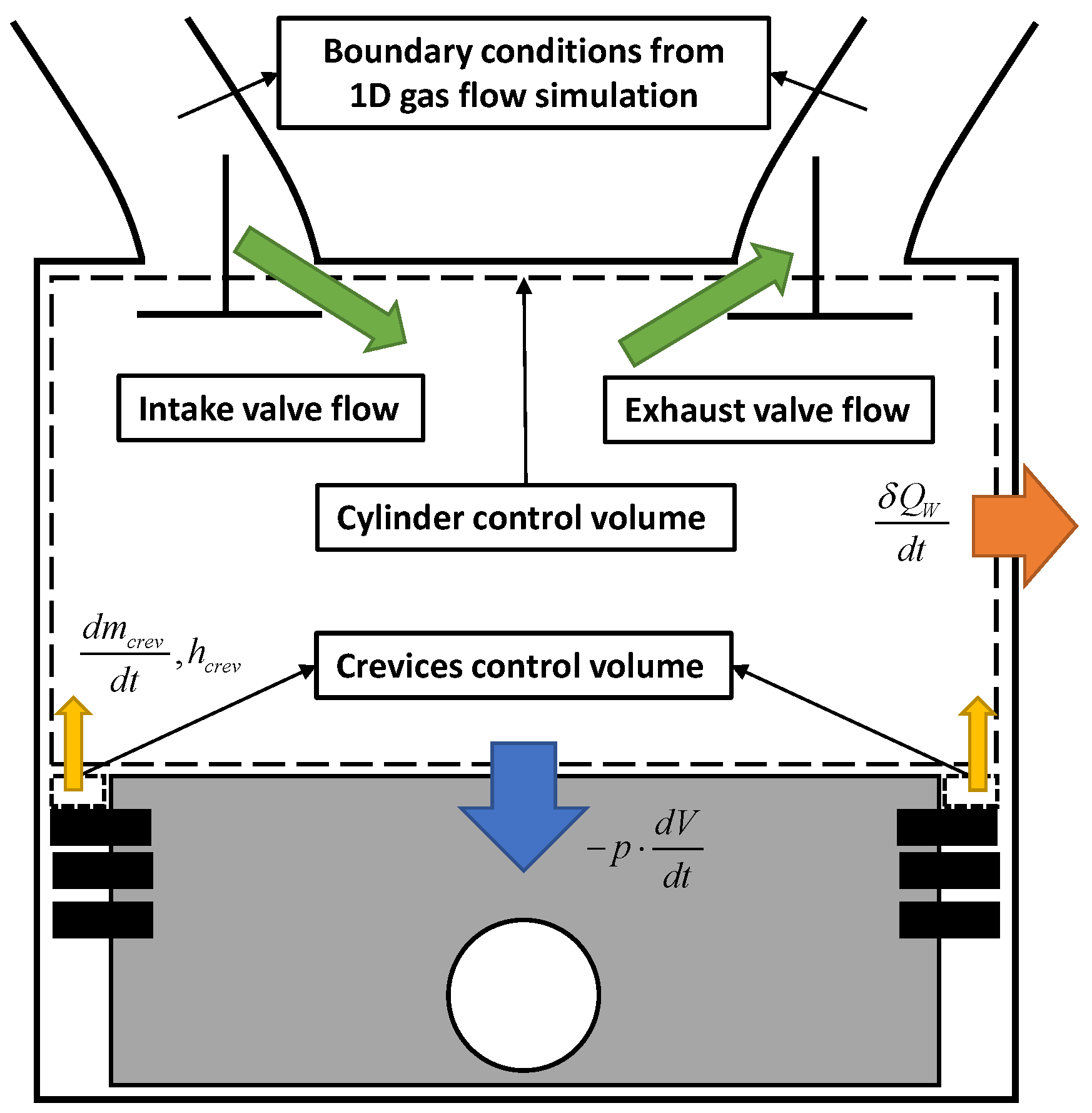
The thermodynamic state and composition are assumed to be homogenous in all zones at the beginning of each engine cycle when the intake valves close. At that stage, the initial conditions of the simulation are passed to the developed model by the 1D simulation of the flow in the intake and exhaust pipes (see
Figure 2).
Below, the hypotheses of the presented multi-zone model are listed:
The fluid in the combustion chamber is treated as an ideal gas.
The pressure in the cylinder is homogeneous.
The zones have the same mass.
No interzonal mass exchange.
Blow-by effects are neglected.
The variation of the energy contribution of each zone during the engine calculation can be addressed to several phenomena, such as combustion, heat transfer, liquid species evaporation, and interzonal work exchange. The chemical auto-ignition is the main responsible for variations in the zonal species composition. Based on these assumptions, the energy balance in each zone writes as:
where the term
pdVz/dt is the work produced by the volume variation due to the expansion or contraction of the zone, the term
δQW,z/dt is the heat transfer to the wall, the term
δQvap,z/dt is the heat loss for the fuel evaporation,
dmcrev,z/dt is the mass flow interchanged with the crevices (assumed positive if ejected from the crevices) and
hcrev is the enthalpy of the flowing gas (calculated with an upwind approach). The total crevices mass flow,
dmcrev/dt, is evenly split among the zones using the zone mass fraction
xz =
mz/m.
is the total energy content, defined as:
where
ei,z, and
xi,z are the specific internal energy and the mass fraction of species
i-th in the zone
z-th. The temperature time-derivative is obtained through a rearrangement of Equation (2) as:
Using the gas state equation applied to the whole cylinder (
pV = ΣzNzone mzRzTz) with Equation (4), the pressure evolution can be written as:
The energy released by the composition evolution is considered in Equation (4), through the term which describes the species variation rate
dxi,z/dt. This last is computed as:
where
Mi is the molar weight of
i-th species,
ρz is the gas density of the
z-th zone,
dωi,z/dt is the molar production or consumption rate of species
i-th per unit volume [mol/m
3s] related to chemical kinetics evolution, and
xcrev,i is the mass fraction of
i-th species of the gas flow between the cylinder and the crevices. A simple empirical correlation is used for the evaluation of liquid fuel evaporation in the cylinder. The evaporation rate is assumed to scale with cylinder temperature and rotational speed in order to sense the dependence of operating conditions. The wall heat losses in the cylinder are computed using the following general formula:
where
Tcyl is the average cylinder temperature,
Thead,
Tliner, and
Tpist are the head, liner, and piston temperature, respectively,
Ahead,
Aliner, and
Apist are the head, liner, and piston wall area, respectively, and
hc is the convective heat transfer coefficient. This coefficient is computed through the Hohenberg correlation [
34]:
where
V is the cylinder volume,
p and
Tcyl are the cylinder pressure and average temperature, and
vp is the mean piston speed.
The overall heat losses
δQW/dt are split among the zones through the
xw,z coefficient. As discussed above, it is mandatory to assign an appropriate and uneven split among the zones of the overall heat transfer exchanged with the cylinder walls to properly reproduce the typical thermal stratification of HCCI engines. Experimental or 3D-CFD analyses [
24,
29] are effective tools to define the heat transfer fraction exchanged by each zone. Those studies point out that the cylinder boundaries exhibit greater heat losses than the inner regions. Moreover, they emphasized that a certain distribution of heat transfer can be applied for a wide range of operating conditions for a certain engine. Nevertheless, the degree of unevenness of the heat distribution profile strictly depends on the combustion chamber geometry characteristics.
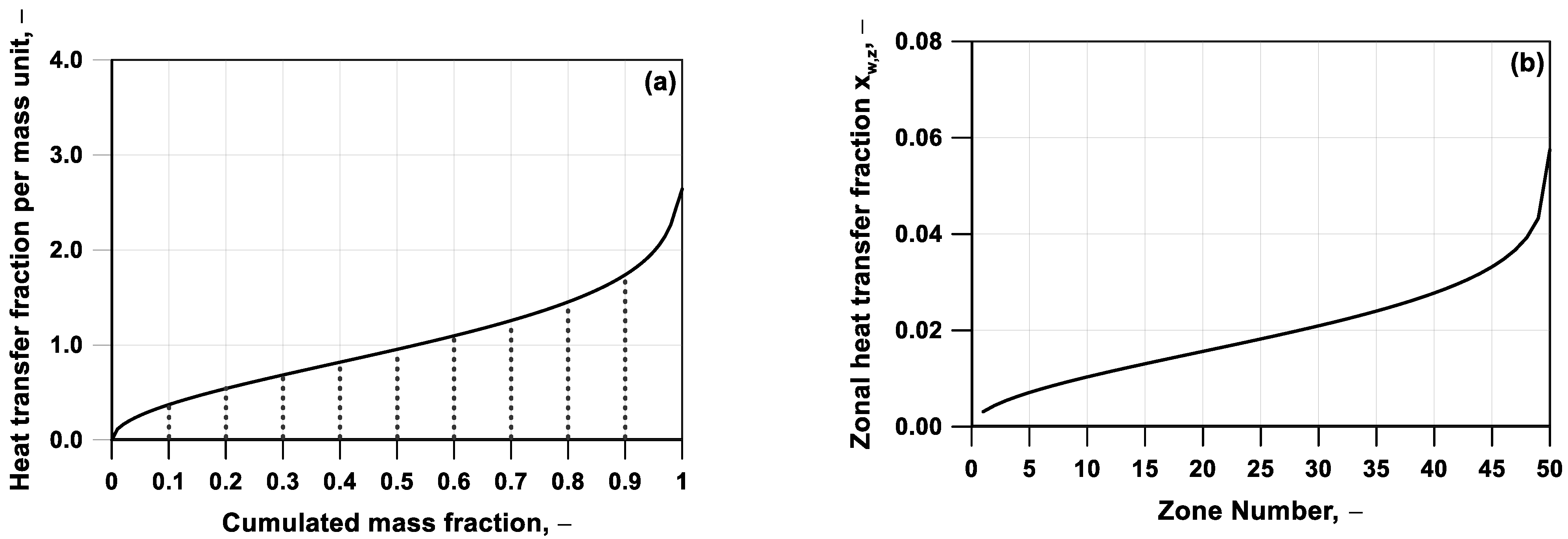
In
Figure 3a, a representative profile of the distribution of heat transfer fraction per unit mass,
xq, against the cumulated mass fraction is illustrated. The
xq is defined as the ratio between the fraction of heat, Δ
QW, exchanged by a fraction of in-cylinder mass Δ
xm,cumul and the mass fraction interval itself (see Equation (9)). The zonal heat transfer fraction, named as
, can be obtained by the integration of the above quantity,
xq. As an example,
Figure 3b depicts the zonal heat transfer fraction for a subdivision of the computational domain in fifty zones of an equal mass.
It is conventionally assumed that the first zone, which presents a quasi-adiabatic behavior, is located in the core of the combustion chamber, while the last zone, which exhibits the highest loss of heat, is adjacent to the boundaries.
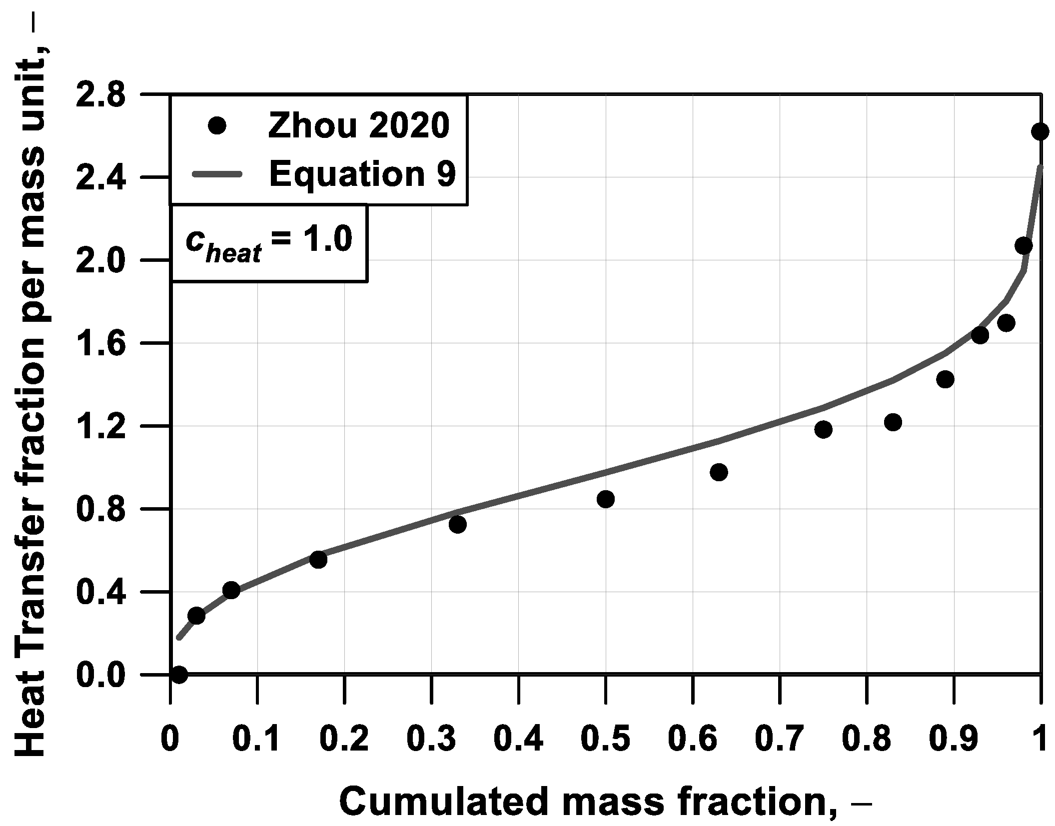
Figure 4 shows the heat transfer profile derived from [
29]. This was estimated by a post-process of experimental data of an engine working under HCCI operations. In the present study, neither 3D CFD nor experimental data are available to identify the wall heat loss distribution peculiar to the analyzed engines. To overcome this lack of information, a parametric function is introduced to describe the heat transfer fraction per mass unit, having the following mathematical formulation:
Equation (9) depends on the cumulated mass fraction
xm,cumul, and mimics the reference profiles presented in
Figure 4. The parameter
cheat allows modifying the unevenness of such distribution, representing a tuning parameter of the presented model. The procedure adopted to identify this parameter and the effect on the combustion evolution will be clarified in the following.
The model has been coupled with sub-models for the estimation of NO
x and unburned hydrocarbons (uHCs). Specifically, in each zone of the combustion chamber, the well-known extended Zeldovich mechanism [
35] is applied to compute the NOx chemistry evolution. A refined model for the evaluation of unburned fuel is implemented, considering the filling/emptying of the crevice volume, and the fuel post-oxidation [
36]. The top land of the piston ring pack is assumed as the unique crevice volume, and the gas trapped in it is expected to be in thermal equilibrium with piston walls. The piston wall temperatures are not available in literature works from which the data of the engines under study were extracted, and hence they are assigned in the simulations according to the authors’ experience on other engines operated with ultra-lean mixtures [
36]. When released from the crevices during the expansion phase, the uHCs are partially consumed according to a simplified chemical kinetic mechanism [
37].
4. Discussion of TKI Methodology Applied to Homogeneous Reactors
Chemical kinetics solver, coupled with a specific chemical mechanism, can be used to obtain the species formation/destruction rate in Equation (6). However, at each time step and each zone, the chemistry solution involves a strong computational effort even with a kinetic mechanism composed of a reduced number of species and reactions. Nevertheless, the estimation of the global performance of an engine, such as heat release rate and pressure cycles, does not strictly rely on the knowledge of the time evolution of each intermediate species. In this perspective, the well-recognized TKI approach [
38,
39,
40,
41,
42,
43] is utilized in this paper. In the TKI approach, the results from offline chemistry calculations in an adiabatic homogeneous reactor are used to describe both the autoignition timing and the heat release due to the ignition of a specified fuel.
A detailed description of the TKI is presented in a previous work of the authors [
44]. For sake of brevity, in this paper, a comprehensive validation of this approach is not presented, but here it is extended to handle blends of two or more fuels in various proportions.
In this perspective, the tabulation process accounts not only for different initial values of pressure,
p, temperature,
T, equivalence ratio,
Φ, and residual fraction,
xr but also the molar fraction of
i-th fuel with respect to the total moles of the fuel blend,
ym,i, as defined below:
In the specific case of engine D, the parameter ym refers to the ethanol concentration and is defined as the moles of ethanol over the total amount of fuel moles. The molar fraction of toluene is fixed at 0.1, and the molar fraction of n-heptane is complementary to unity.
The discrete values considered as initial conditions for chemistry tabulation are shown in
Table 4, summing to 49,500 and 297,000 data for a pure fuel and a fuel mixture, respectively. The initial conditions in
Table 4 are selected to cover the entire possible engine-like conditions. The variation range extension and exploration resolution are selected to give a proper trade-off between the sensitivity of chemistry to the considered parameter and the computational effort.
The main outcome is an extended table, which contains the values of the progress variable time derivative for each combination of initial conditions. The progress variable,
c, is here defined based on the normalized variation of formation enthalpy,
hf, during the autoignition process, according to:
where
t,
t0, and
tf are a generic time, and the initial and final time of the auto-ignition process, respectively. The values of the progress variable time derivative can be then looked up in either engine or homogeneous reactor simulations to evaluate the heat release profile through the amount of fuel that burns in each time step.
Since various fuels are investigated in the presented work, different kinetic mechanisms have been selected to accurately capture the evolution of the combustion in each tested engine. In this regard, hydrogen ignition is modeled by Hong’s kinetic scheme [
45], accounting for 10 species and 20 reactions. For the methane, the well-assessed GRI mech scheme (53 species and 325 reactions) [
46] is chosen, while, for n-heptane, the chemical kinetic scheme taken from the work of Ranzi et al. [
47] is selected (106 species and 1738 reactions). The mechanism taken from the work [
47] is adopted for the n-heptane/toluene/ethanol mixtures (171 species and 3754 reactions).
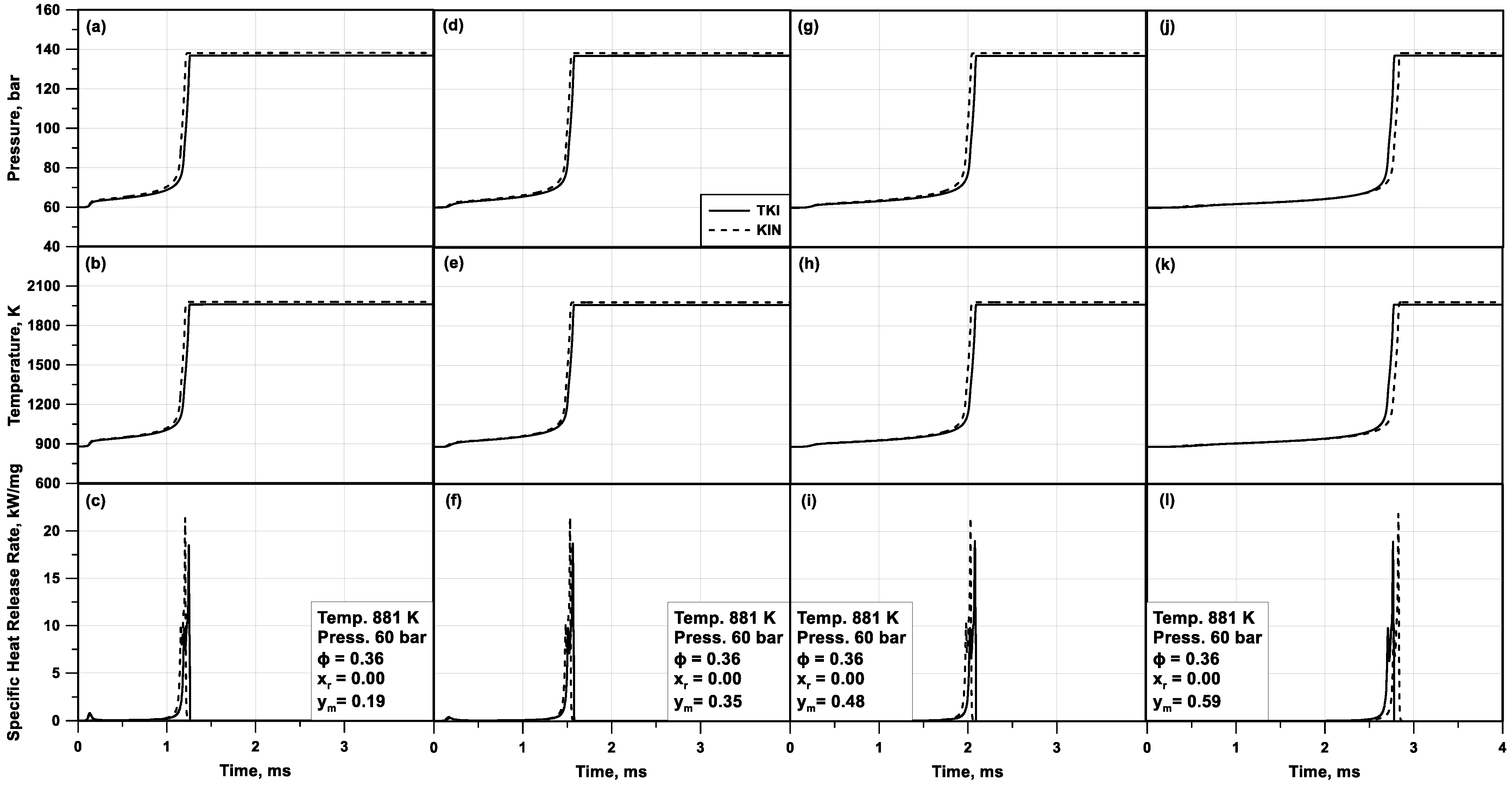
To prove the reliability of the TKI approach, in
Figure 5, the trends of pressure, temperature, and heat release rate in a tabulated chemistry computation are compared to the ones of a standard chemical kinetic solver. Those results refer to a homogeneous adiabatic constant-volume reactor for fixed initial conditions of pressure, temperature, and equivalence ratio and various blends of n-heptane/toluene/ethanol.
Figure 5 underlines that pressure (a,d,g,j), temperature (b,e,h,k), and HRR (c,f,i,l) profiles from tabulated chemistry are very close to chemical kinetics results for all the cases under study. This points out the effectiveness of tabulated chemistry even for fuel mixtures with different fuel proportions. Both methodologies highlight that a higher content of n-heptane in the mixture, which is the most reactive fuel in the blend, and a lower amount of ethanol, lead to a faster auto-ignition. It is worthwhile mentioning that the tabulated chemistry executed much faster than the detailed kinetics, having an average reduction in the simulation time of three orders of magnitude in the presented example. Less relevant advantages are advised in the previous work of the authors, where a single-component fuel was analyzed [
44].
5. Tuning Procedure
The presented model does not have any parameter that allows direct control of the combustion evolution, while the heat exchange with the cylinder walls can be suitably tuned. Additionally, the overall amount of wall heat losses can be globally adjusted by a multiplier of the heat transfer correlation. Indeed, the local temperature level in the cylinder can be manipulated by the heat transfer distribution, already discussed in
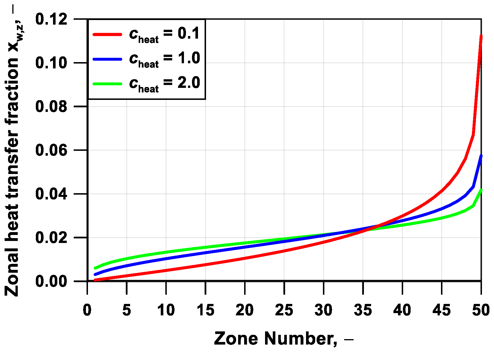
Section 3. This can be modified by a control parameter to adjust the degree of unevenness of the wall heat losses by the cylinder zones. Of course, this also reflects on the combustion onset and evolution. As an example,
Figure 6 depicts the wall heat fraction lost as a function of the zone index for three values of the tuning parameter
cheat. Trends of the in-cylinder pressure and progress variable, respectively in
Figure 7a,b, highlight that a more even (uneven) wall heat loss distribution leads to a delayed (advanced) initiation of the auto-ignition process, together with a steeper (more progressive) pressure rate. In other words, the increase of the heat fraction unevenness causes both an earlier pressure rise rate due to the quasi-adiabatic behavior of the inner regions and also a delayed or even incomplete combustion of the outer zones, which exchange a huge amount of heat with the walls. On the contrary, an almost flat heat transfer fraction profile involves late and almost simultaneous autoignition of all the zones.
Based on these observations, the tuning of the wall heat transfer fraction and the global heat transfer multiplier is carried out for each engine under study, having the aim to match the experimental values of combustion phasing and in-cylinder pressure profile. For each engine, those parameters are kept fixed in all the examined operating conditions. The identified optimal values of those tuning parameters are listed in
Table 5. The global heat transfer multiplier is quite similar among the tested engines, confirming the robustness of the adopted heat transfer correlation. The parameter controlling the thermal stratification,
cheat, assumes the same value for all engines, except for Engine B. This is the only engine with a high compression ratio, which leads to a flat combustion chamber across the TDC. This probably reflects in a more homogenous temperature distribution in the cylinder, which required a greater value of
cheat.
Table 5 also reports the volume of the crevice volumes expressed as a percentage of the in-cylinder volume when the piston is at the TDC. Note that the value for Engine B/C is taken from [
31], whereas the values for Engine A and D, are assumed by a trial and error tuning process, aiming at reproducing appropriately the in-cylinder pressure trace and the uHC emissions.
It is worthwhile mentioning that all parameters of the model listed in
Table 5 are kept fixed for each operating condition and only depend on the engine under study.
Another important setting in a multi-zone model is the number of zones in which the cylinder is subdivided. From the point of view of the simulation time, a reduced number of zones can reduce the computational effort and leads to a faster evaluation of the in-cylinder process. Instead, a higher number of zones can predict in a more detailed way the performance and the pollutant emissions of the specific engine condition thanks to a more refined discretization of the in-cylinder temperature field. In order to identify the proper number of zones complying with the two objectives described before, a sensitivity analysis of the zone number is performed for test case #5 of
Table 3.
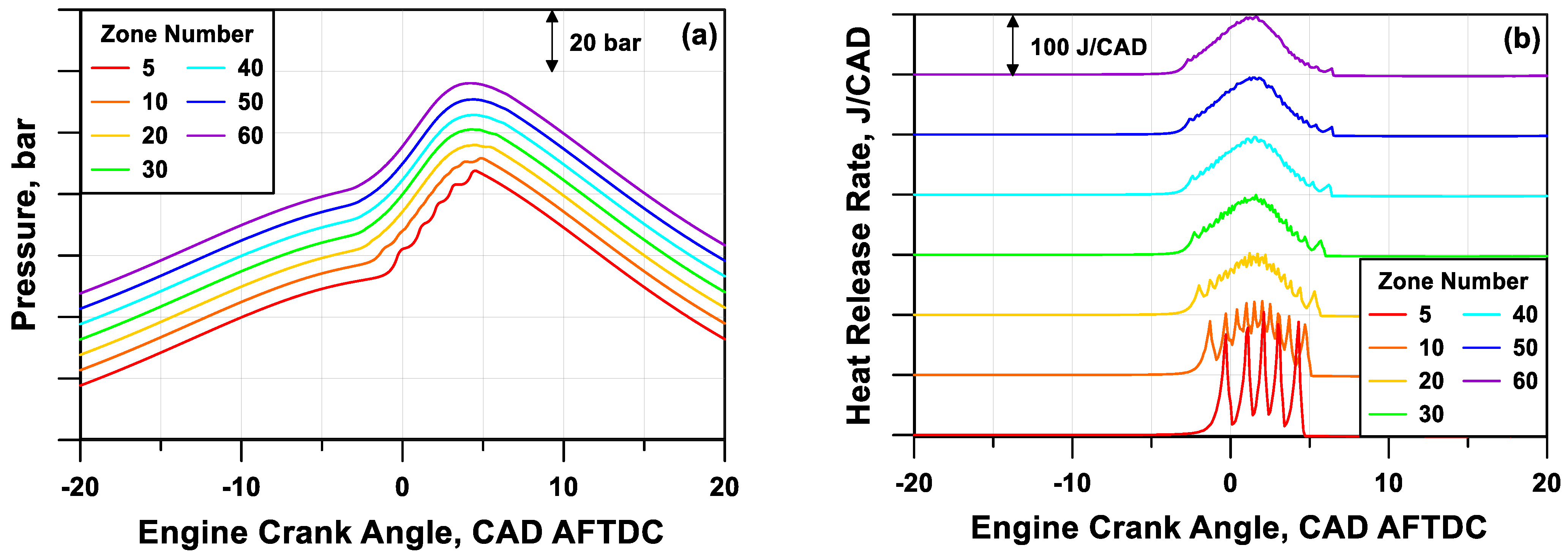
The observation of the pressure and heat release rate profiles in
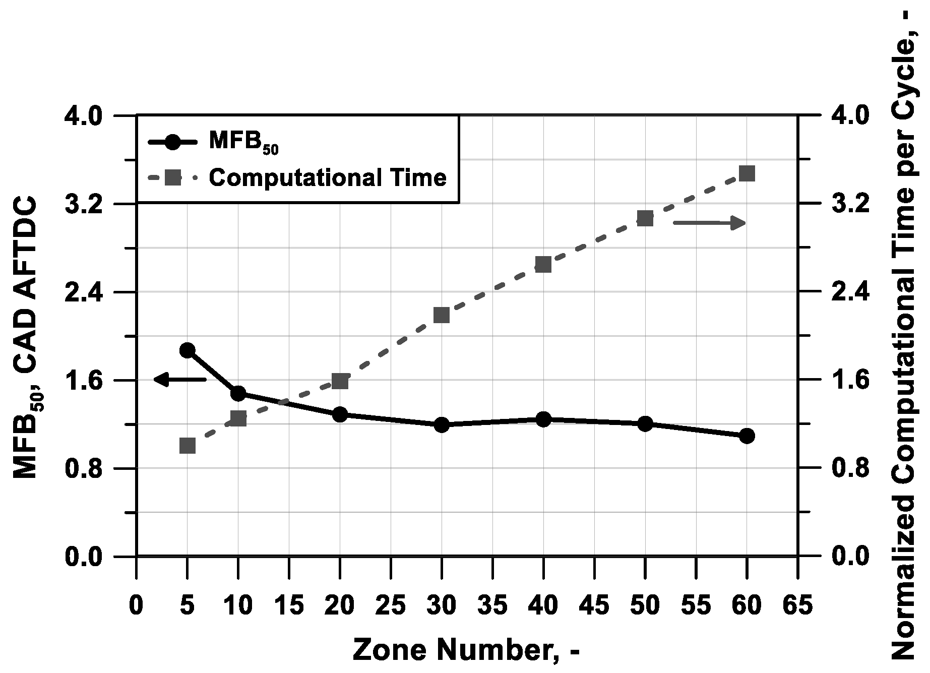
Figure 8a,b, respectively, (shifted on the y-axis to improve the readability) puts into evidence that a reduced number of zones leads to a rough pressure trace, instead, a higher number of zones can simulate a smoother and realistic pressure evolution. The cylinder mass discretization also affects the start and phasing of the combustion; this last is here identified as the angle when 50% of the mass is burned (MFB
50).
Figure 9 highlights that a number of zones equal to, or higher than, 30 is necessary to reach the solution invariance in terms of MFB
50 angular position. The figure also puts into evidence that an increase in zone number causes an almost proportional lengthening of the simulation time, represented as the time needed to compute an engine cycle.
In light of the above considerations, a discretization with 50 zones is chosen as a reasonable compromise between invariance of the results, smoothness of the pressure cycle and heat release rate, and computational time. The same discretization is also applied for all engines and test cases considered in this work.
6. Model Validation
In this section, the model reliability will be proved by the assessment between the computed and experimental traces of in-cylinder pressure and heat release rate for all engines under study and operating conditions in
Table 3. Moreover, the model consistency will be further verified in terms of NOx and uHC emissions. The first verification of the model reliability is demonstrated for Engine A in operating conditions #1, #2, and #3 of
Table 3. In these tests, the engine is fuelled with an ultra-lean air/hydrogen mixture with various temperatures of the intake air.
An excellent agreement between numerical and experimental traces can be observed in
Figure 10 for the analyzed cases. Comparing the experimental and numerical data, an average relative error of 1.0% on the firing pressure peak is observed, and an absolute error of 0.34 CAD on its position emerges. The model is able to perceive the advance of the combustion when the intake air temperature increases and, correspondingly, the more intense heat release rate.
The numerical pressure and heat release rate profiles are compared to the experimental data in
Figure 11 and
Figure 12 for Engine B and C fuelled with methane (cases #4 to #6 in
Table 3) and n-heptane (cases #7 to #9 in
Table 3), respectively. The model can appropriately match the experimental traces, especially for methane cases. Globally, heat release rate traces and peak values are well captured for different mixture compositions and thermodynamic conditions, without case-by-case tuning. An average relative error of 1% on the firing pressure peak is observed, and an absolute error of 0.69 CAD on its position is detected. Some inaccuracies are visible with the n-heptane engine, especially concerning the cool flame description. Compared to the experimental counterpart, the computed cool flame heat release appears shorter and more intense. This is due to the inability of TKI to predict, from a thermochemical point of view, the effects of intermediate species, which are relevant for the ignition of long-chain fuels, such as n-heptane.
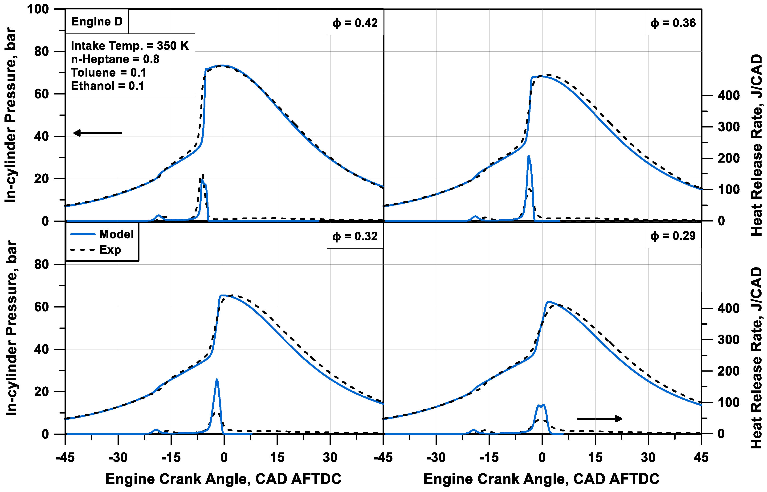
More extensive model validation is proposed for Engine D, which is supplied with blends of n-heptane, toluene, and ethanol. Comparisons in
Figure 13 refer to a sweep of fuel composition, by reducing the content of n-heptane and increasing the amount of ethanol passing from case #10 to #12 at a fixed
Φ of 0.4. The figure highlights that the larger the n-heptane amount (smaller content of ethanol), the more intense the cool flame. The model proves to capture quite well this behaviour, even if the timing of the cool flame is missed. The numerical simulation in most cases well detects the time when the high-temperature reactions occur, and the main combustion phase takes place. Nevertheless, the in-cylinder pressure peak and the heat release rate are generally overestimated in this phase. An average relative error of 2.4% on the firing pressure peak and an absolute error of 1.1 CAD on its position are observed. This probably represents a lack of the tabulated chemistry approach, where a differentiated consumption of each fuel in the mixture cannot be accomplished and the tracking of each species during auto-ignition is not realized. Similar considerations apply to the results in
Figure 14, which refer to a sweep of
Φ (cases from #13 to #16 with
Φ passing from 0.42 to 0.29) with a fixed composition of the fuel. A certain heat release rate overprediction occurs in cases with medium air/fuel proportions. This could be justified with the same explanations discussed above. Comparing the firing pressure peak value and its angular position, an average relative error of 1.0% on the firing pressure peak is observed, and an absolute error of 1.7 CAD on its position is observed.
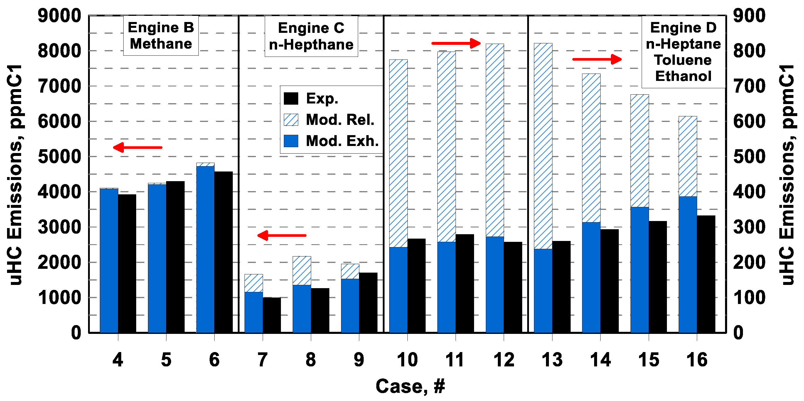
Figure 15 shows the numerical/experimental comparisons of unburned hydrocarbons for the engines supplied with carbon-based fuels, namely Engine B, C, and D. The plots are in the form of a bar chart and report the uHC concentration expressed in ppmC1. Each bar is numbered according to
Table 3 and numerical results refer to both uHC released by the crevices, before post-oxidation (slash bars, labeled as Mod. Rel.), and their residual amount, after the post-oxidation process (solid bars labeled as Mod. Exh.). The model can emulate the production of uHCs with satisfactory accuracy in almost all the analyzed operating conditions, with a maximum relative error of about 16% (Cases #7 and #16), an average relative error of 8.4%, and most of the cases with a relative error below 10%. It is worth noting that the simulation follows correctly the uHC increase for Engine B and C when the air/fuel mixture becomes less lean. According to the theoretical expectations, the extent of the post-oxidation is marginal or null in the case of methane and more relevant in the case of n-heptane.
Globally, the level of uHC emissions is captured quite well by the model for Engine D. Numerical results in
Figure 15 highlight that the uHC concentration before the post-oxidation process is mainly related to air/fuel proportion, with lower levels when the mixture is leaner. Post-oxidation becomes less intense when the air/fuel mixture is leaner, due to lower in-cylinder temperature levels, leading to an increase of uHC emission at the cylinder-out. This phenomenology highlighted by the simulations appears a reasonable explanation for the experimental trends of uHC depicted in
Figure 15 for cases #13–#16 (
Φ sweep). In cases #10–#12, the uHC emissions are quite similar in both numerical and experimental data, having the same air/fuel proportion. As a final consideration, the overall differences in uHC emissions for engine B/C and engine D mainly rely on the dimension of the crevices volume (see
Table 5).
The most probable explanation for the uHC model inaccuracies is the uncertainties about the piston wall temperature, which affects the trapped mass within the crevices. For Engine D supplied with a fuel blend, another possible reason for uHC prediction errors might be the incapability of the presented TKI approach to determine a differentiated consumption of the fuels according to their specific reactivities. Moving towards the combustion completion, the fuel blend is expected to enrich with the less reactive fuel (ethanol in the considered case), also affecting the post-oxidation reaction rates. This phenomenology cannot be handled by the adopted TKI approach, where all fuels are consumed at the same relative rate, hence maintaining the relative proportions.
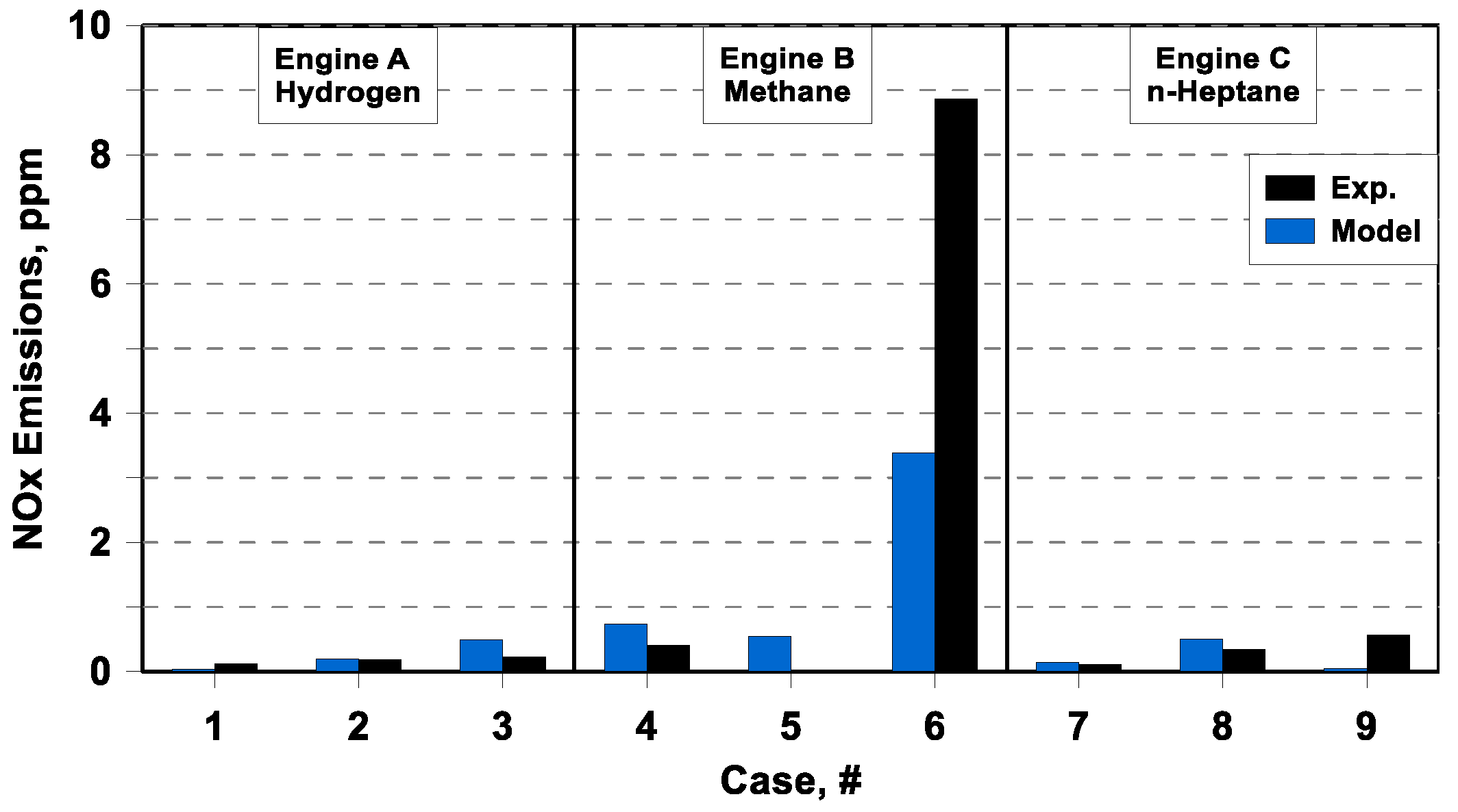
The numerical/experimental comparison of nitric oxide emissions is depicted in
Figure 16, as the previous one in the form of a bar chart. Those comparisons show that the model has the possibility to simulate extremely low NOx emission, typical of an HCCI combustion.
The model also evidences the possibility to feel the increase in NOx production that occurs for the less lean case, for which the in-cylinder temperatures reach the highest levels (see equivalence ratio of cases # 6 in
Table 3). It is worthwhile mentioning that such low concentrations of NOx, in most cases below 1 ppm, are comparable to the sensitivities of the experimental instruments. Hence, any discussion about quantitative metrics of the NOx model error does not appear significant.
7. Conclusions
In this study, a multi-zone HCCI combustion model integrated with fast tabulated chemical kinetics is presented and validated against several experimental data, different in terms of the fuel supplied (hydrogen, n-heptane, methane, and n-heptane/toluene/ethanol blend), engine characteristics (compression ratio, displacement, etc.), and operating conditions (intake pressure and temperature, EGR rate).
The main feature of the presented model is the tabulated kinetics of ignition, which, combined with a control-mass Lagrangian framework, produces a good balance between computational burden and simulation accuracy.
Thermal stratification, typical of the HCCI engine, is obtained through a parametric function to describe the zonal wall heat transfer losses. For each engine under study, this function is identified and kept fixed for every considered operating condition.
The TKI methodology has been validated against a conventional chemical kinetic solver in a constant-volume homogeneous adiabatic reactor, showing satisfying accuracy and a much faster simulation time (reductions of three orders of magnitude in the presented results).
The reliability of the HCCI multi-zone model has been evaluated with reference to pressure profiles, heat release rate, and pollutant emissions. The numerical results showed a good agreement with the experimental profiles, with an average relative error of 1.3% on the in-cylinder pressure peak and an average absolute error of 0.95 CAD on the pressure peak angle, although some criticisms emerged in predicting the heat release rate intensity when the combustion is primarily controlled by intermediate highly reactive radicals, such as n-heptane auto-ignition. In addition, the uneven consumption of different fuels in the blend is a critical point. These two criticisms are related to the simplified assumptions of the tabulated chemistry approach. The model correctly detects the very reduced levels of NOx emission deriving from low-temperature combustion with an absolute error that is below 1 ppm for almost all cases, as well as captures uHC emission variations due to crevices volume size, in-cylinder thermal level, and air/fuel proportions with a maximum relative error of 16%, and a relative error below 10% for most of the cases.
The methodology was demonstrated to be a reliable tool to investigate the operation of an HCCI engine, which may be applied in the development of a new engine control strategy or new architectures working under this advanced combustion mode.
For future developments, the overcoming of the criticisms related to the incorrect description of the intermediate reactive radicals and the differentiation of the oxidation of different fuels seems to be an important improvement. This would also help in advancing the description of the post-oxidation process, leading to better capabilities of the unburned hydrocarbon sub-model.
