


Electric Vehicle Charging Systems: Comprehensive Review

 ,
, 
 , and
, and
Abstract
1. Introduction
1.1. Motivation
1.2. Paper Novelties
- An EV charger’s classification and topologies review are performed. Accordingly, the EV charger’s classification is addressed, and each type of EV charger is briefly described. Then, the focus is placed on the available EV charger topologies. Particularly, bidirectional structures are highlighted, and the available topologies are compared;
- An overview of the available EV charging standards is given. American SAE J1772 standard, European IEC 61851 standard, and Chinese GB/T standards are mainly presented. The related EV charging modes/levels are described, and their specifications are listed.
- A state-of-the-art in EV charging coupler is addressed. Therefore, the SAE J1772 coupler, the IEC type 2 coupler, the combined charging system (CCS) coupler, the CHAdeMO coupler, the GB/T coupler, and the Tesla coupler are described. Rated parameters and pinouts of each coupler are also given;
- A review of the most used batteries in EV applications is fulfilled. First, a classification of EV batteries is accomplished. Finally, the battery terminologies and the most well-known battery-charging methods are described.
1.3. Paper Organization
2. Classification and Topologies of EV Charger
2.1. EV Chargers Classification

| EV Chargers | Description |
|---|---|
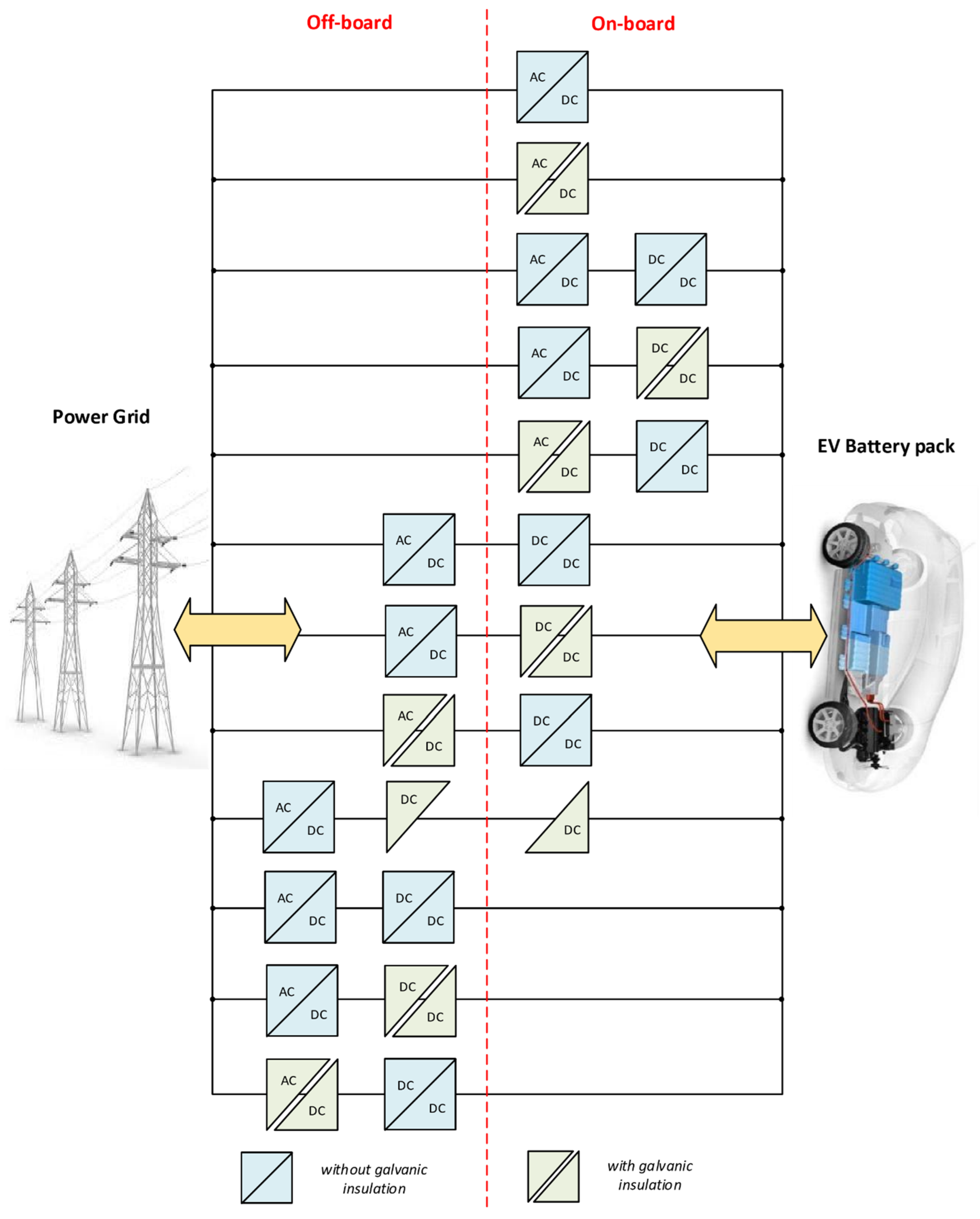
| Offboard chargers | All the components required for the EV charging and discharging process are inside the public EV charging station [32,33]. |
| On-board chargers | Some components required for the battery-charging process are embedded inside the EV. |
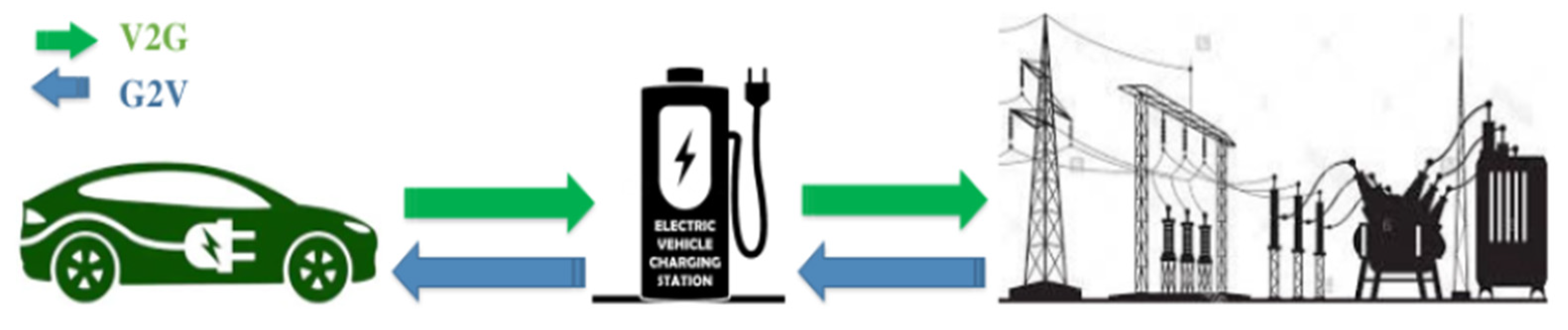
| Unidirectional chargers | The electrical energy transfer is one-way from the EV charging station to the EV battery. Therefore, only the G2V operation mode is possible. |
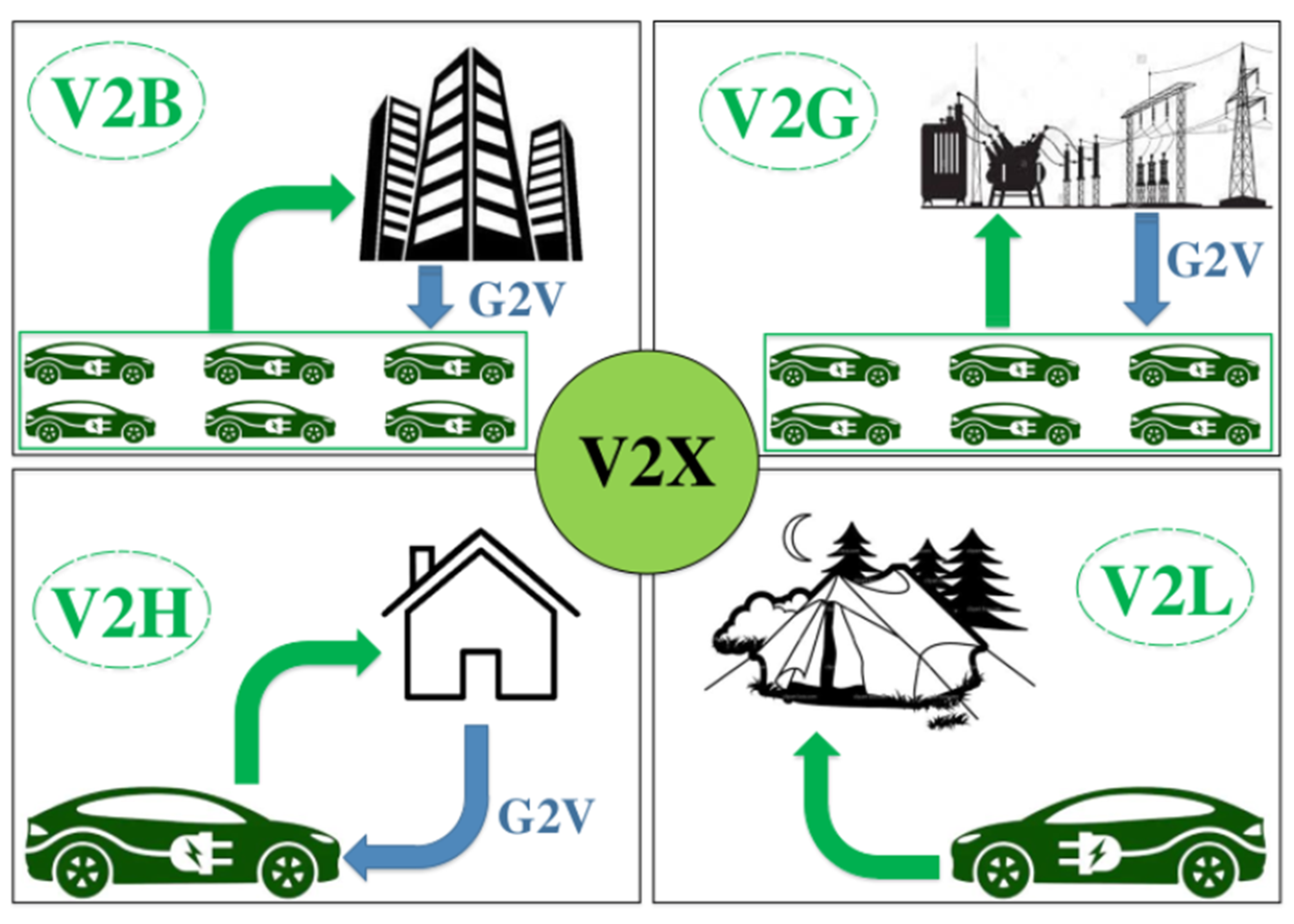
| Bidirectional chargers | The electrical energy flow can be from or to the EV battery. Thus, V2X technology can be ensured by this type of charger [34]. |
| Dedicated chargers | All equipment making up the charger is exclusively utilized to guarantee the EV charging or discharging process. |
| Integrated chargers | When the EV is linked to the electricity network, the traction system constituents (Motors, inverters, etc.) are used to guarantee the EV charging or discharging process [35]. |
| Conductive chargers | A dedicated electrical cable links the EV to the electricity network. |
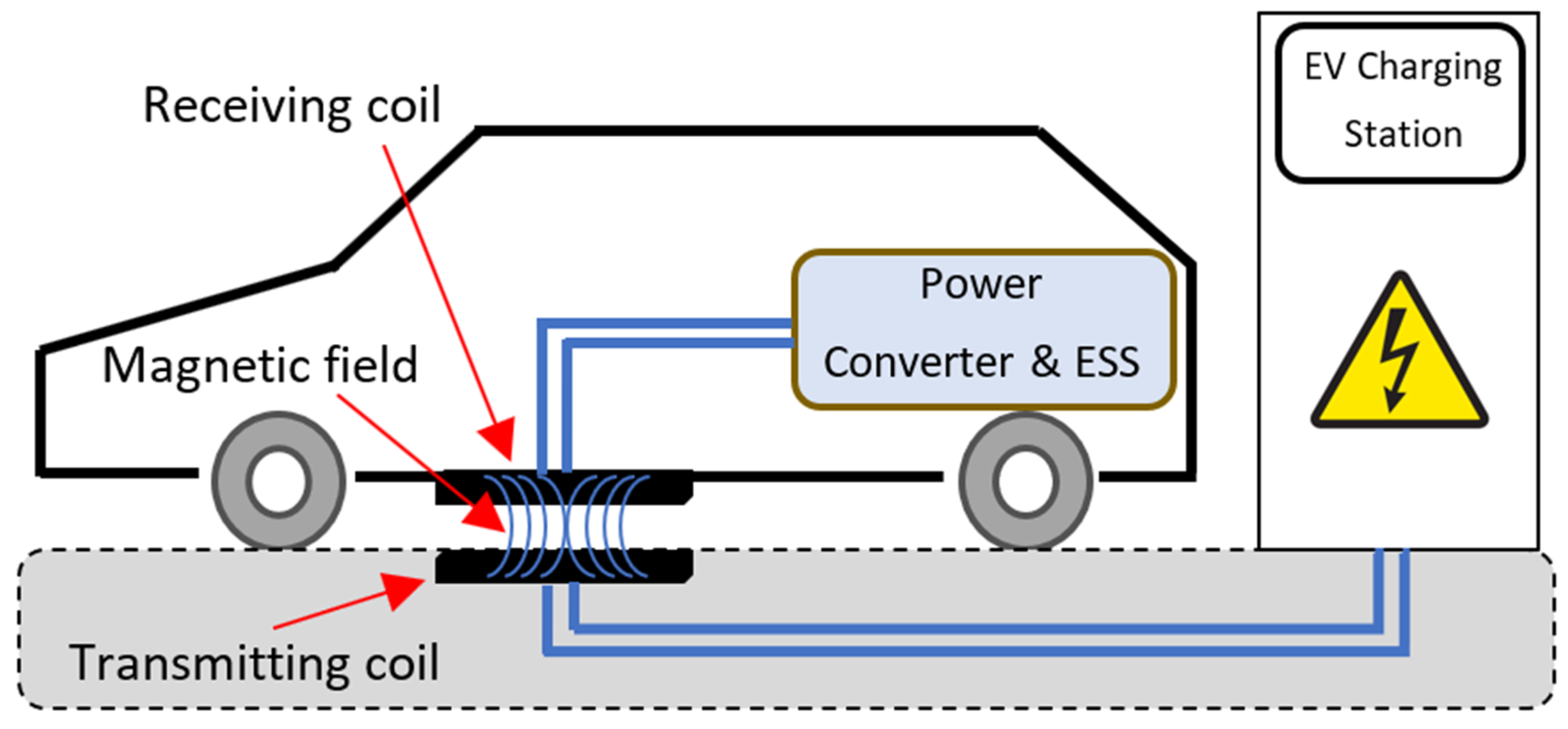
| Wireless Power Transfer Chargers [36] | It is a contactless charging technology. No cables are utilized between the EV and the electricity network [37]. Instead, the electrical energy transfer is based on electromagnetic induction [38]. Figure 6 illustrates the concept of this EV charger type [39]. Compared with conductive chargers, these inductive chargers present various advantages [40]. Especially the convenience for the user and the intrinsic galvanic insulation, while the cost and the need for custom hardware inside the EV are the main drawbacks [41,42]. |
| Single-stage & Dual-stage chargers | The first one consists of a single power conversion: only one ac-dc or one dc-dc power converter. The second one involves double power stages: ac-dc and dc-dc power conversions. |
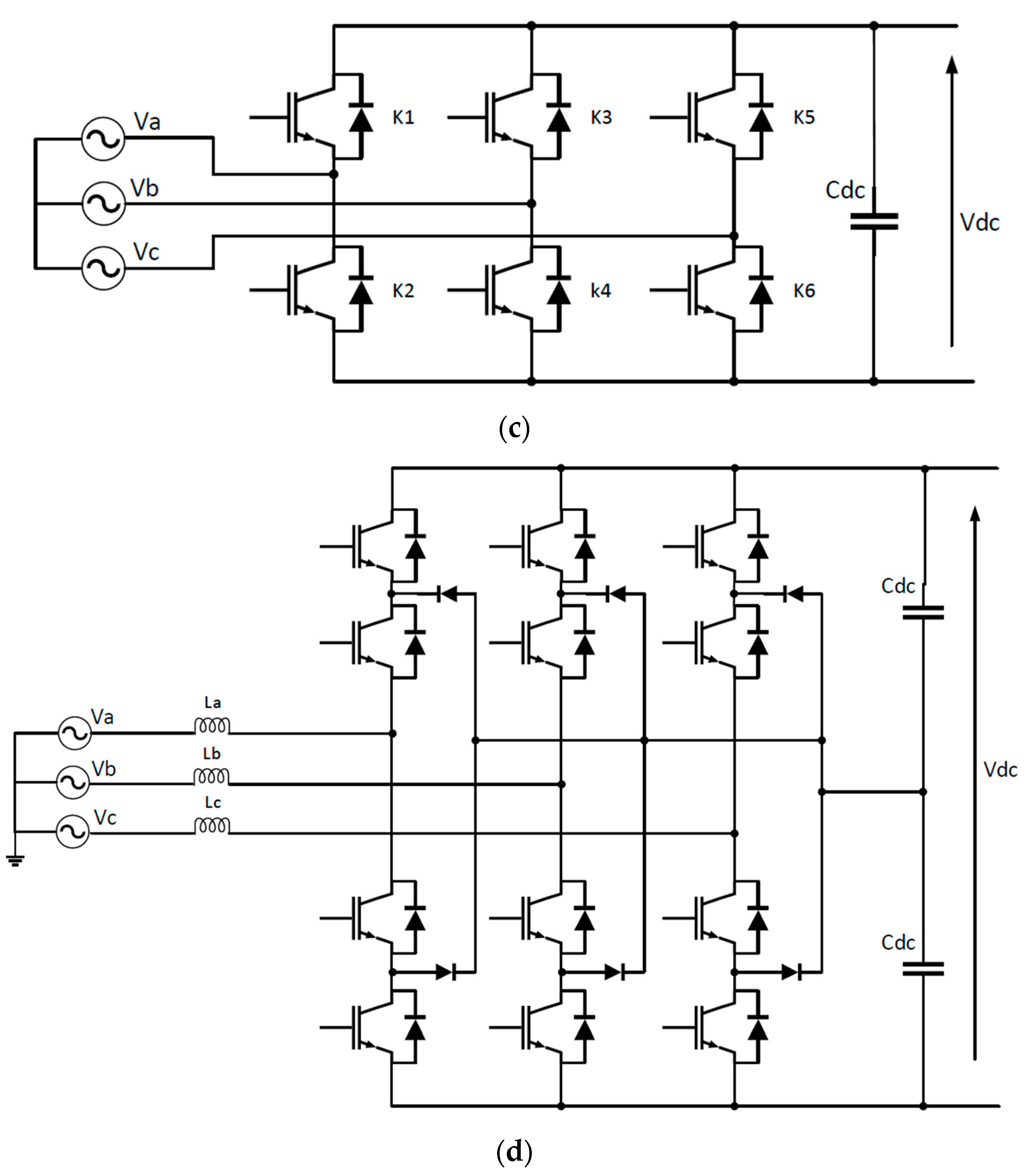
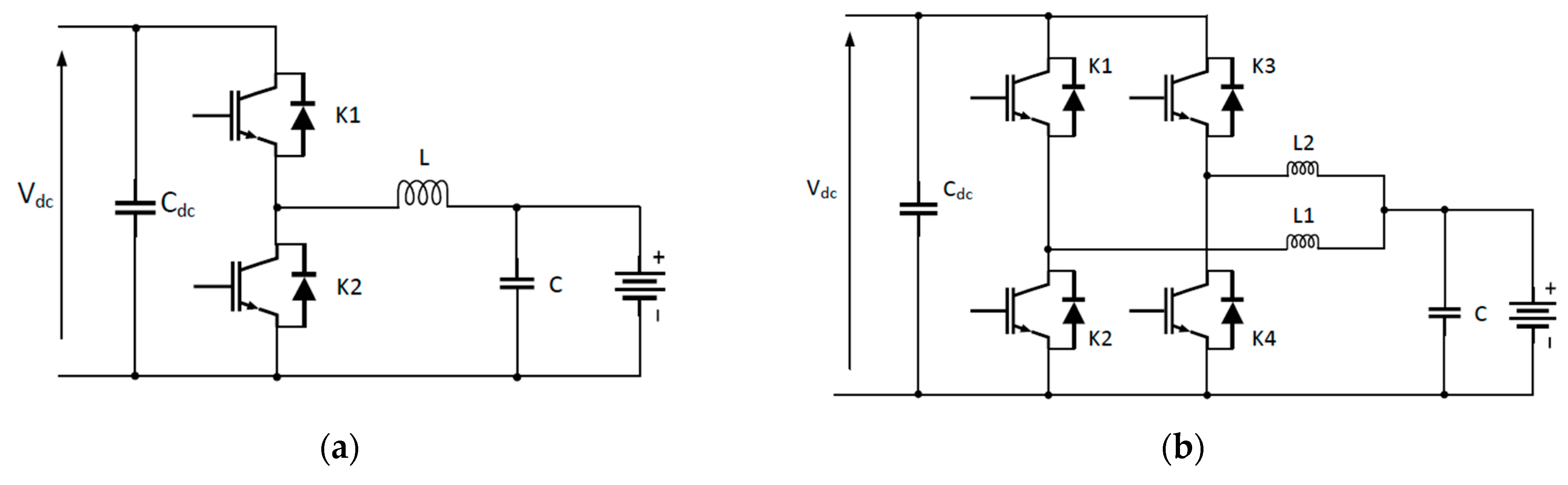
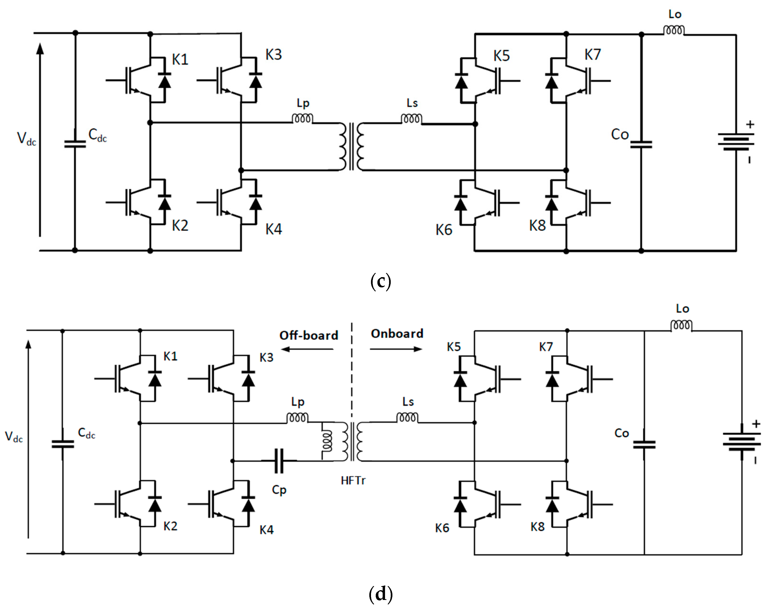
2.2. EV Charger Topologies
3. EV Charging Standards Overview
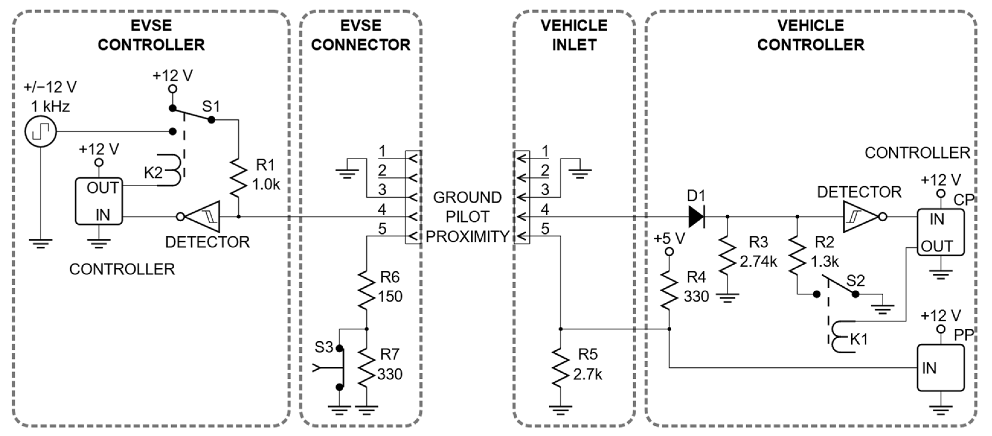
3.1. SAE J1772 Standard
3.2. IEC 61851 Standard
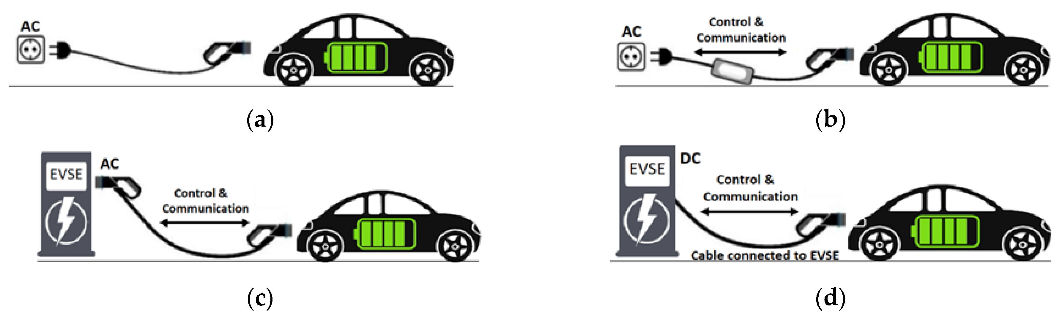
- Mode 1 (also known as Schuko mode) relates to charging an electric vehicle from a standard household socket using a basic extender cable without protective equipment. Furthermore, this standard domestic socket is protected using a slow fuse, making this charging mode extremely unsafe. For that reason, the Schuko charging mode is strongly discouraged in many parts of the world.
- Mode 2 relates to charging an electric vehicle from a standard domestic socket augmented with a control and protection system installed inside the cable (well-known as in-cable control and protection device (IC-CPD)). Compared to Mode 1, this charging option is far less dangerous. Nevertheless, the charging capacity will be constrained by the maximum power of the socket outlet.
- Mode 3 relates to adequately controlled and protected dedicated AC charging stations. It’s the usual charging mode worldwide, with a power range from 3.7 kW to 43 kW.
- Mode 4 is the DC charging mode. The public EV charge point directly supplies DC voltage to the EV battery pack. Therefore, the EV on-board charger is bypassed.
3.3. China GB Standards
4. State of the Art of EV Charging Couplers
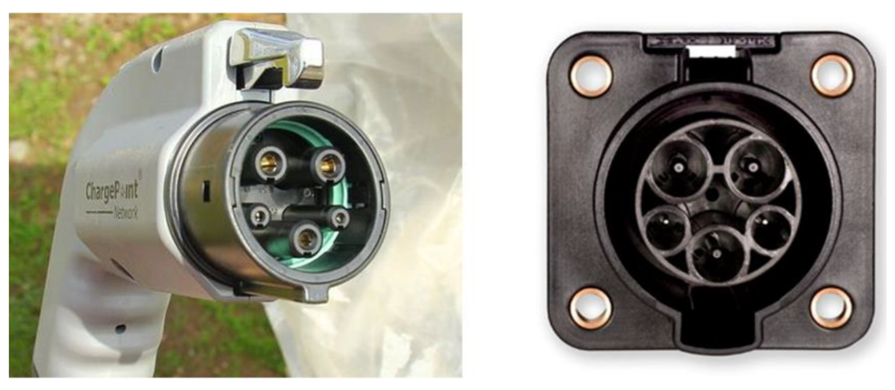
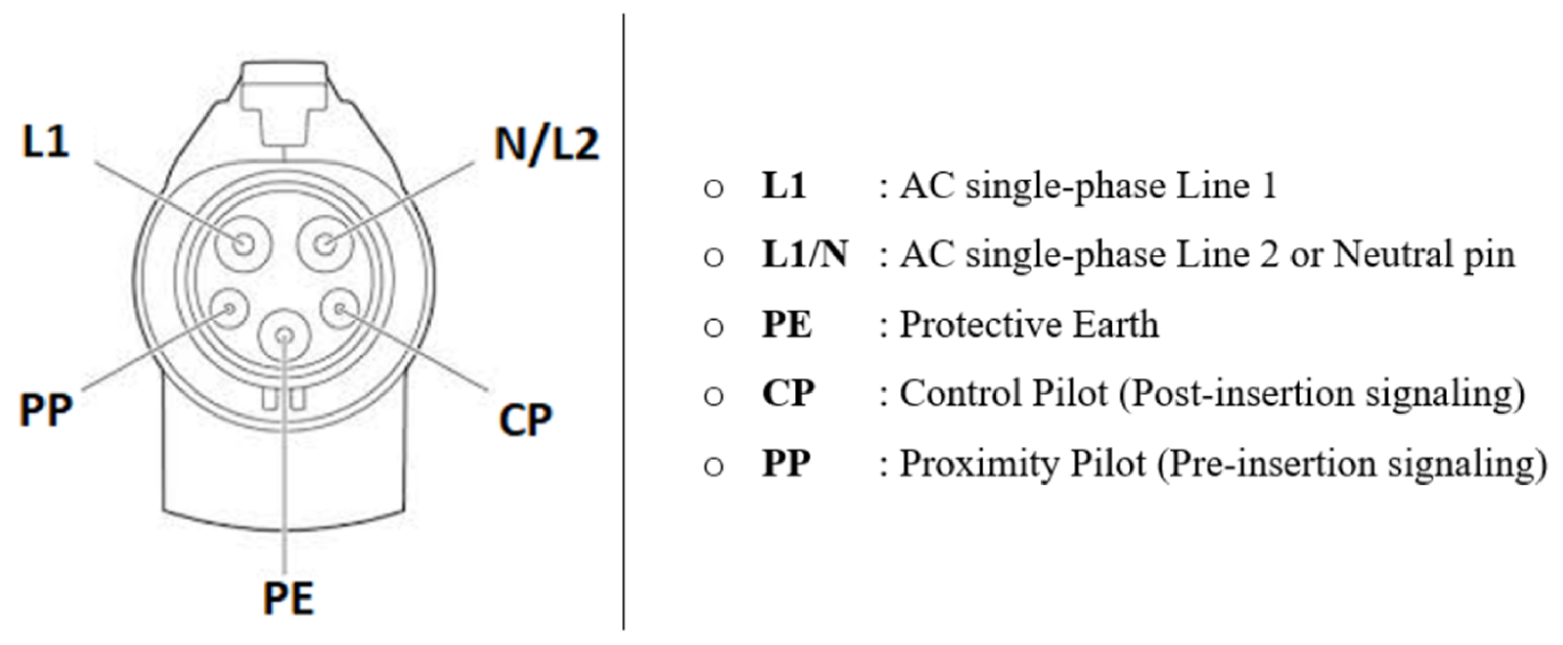
4.1. SAE J1772 Coupler
4.2. IEC Type 2 Coupler
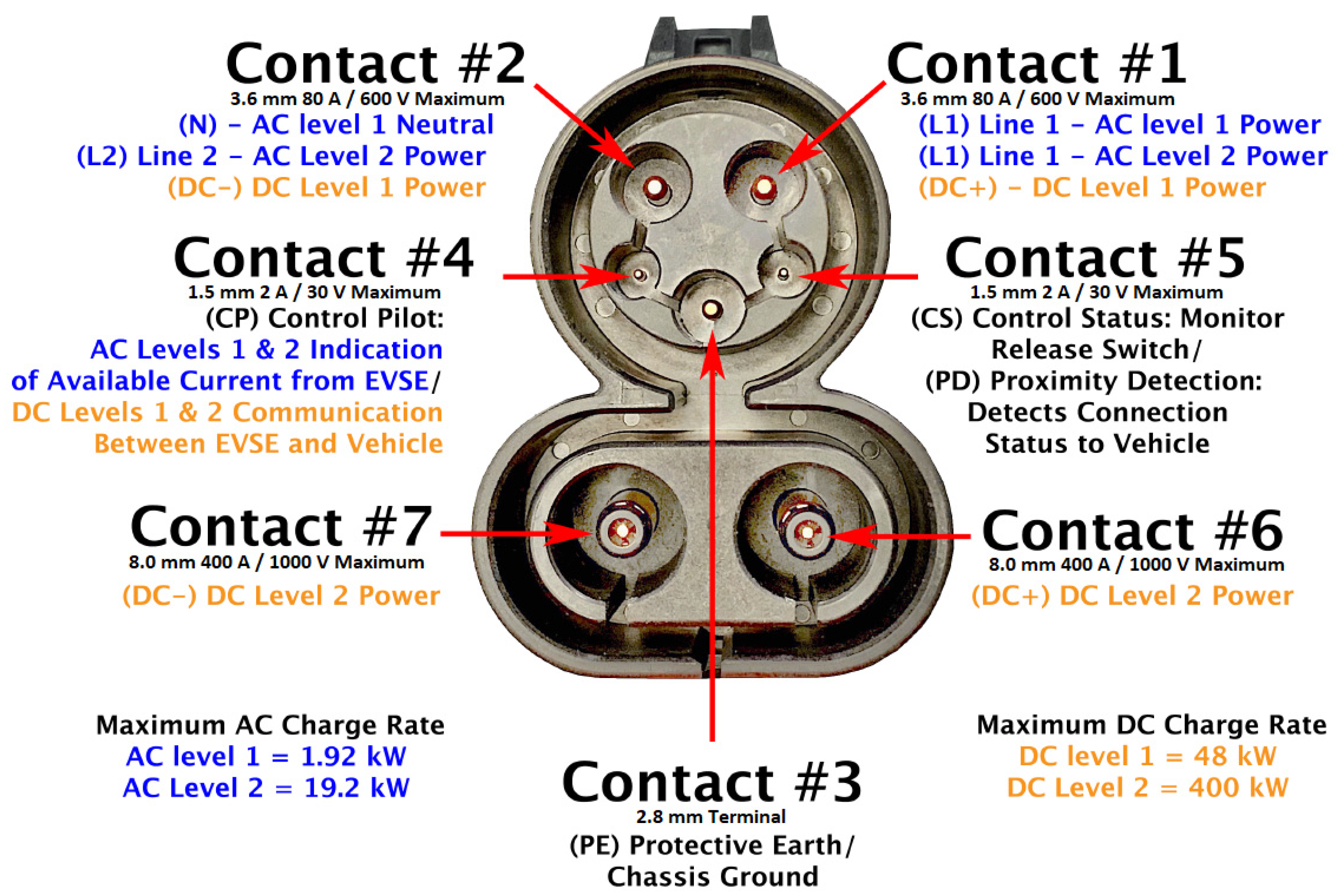
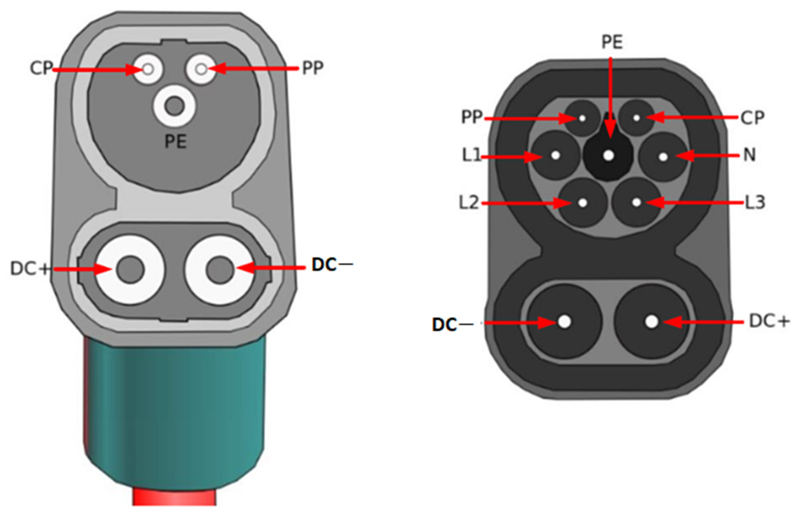
4.3. CCS Combo Coupler
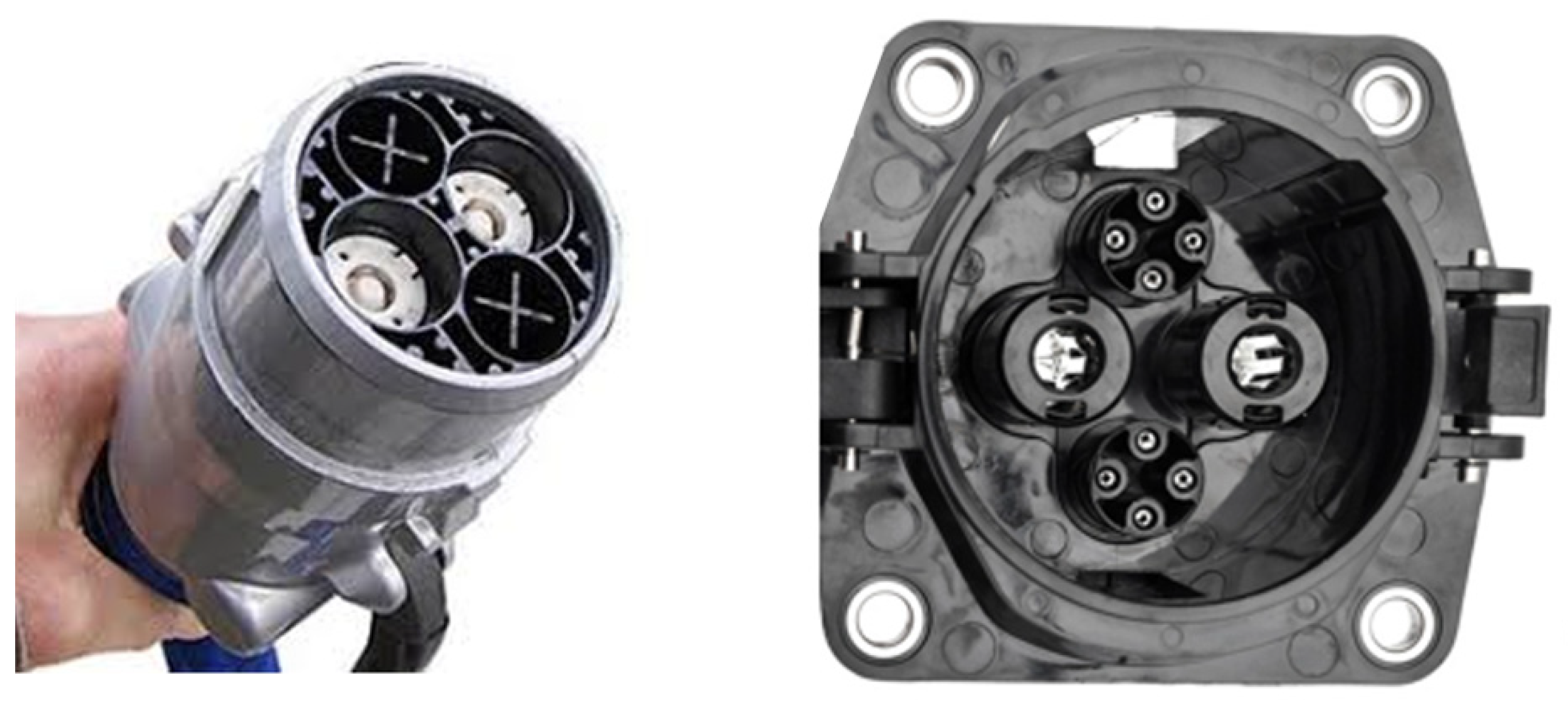
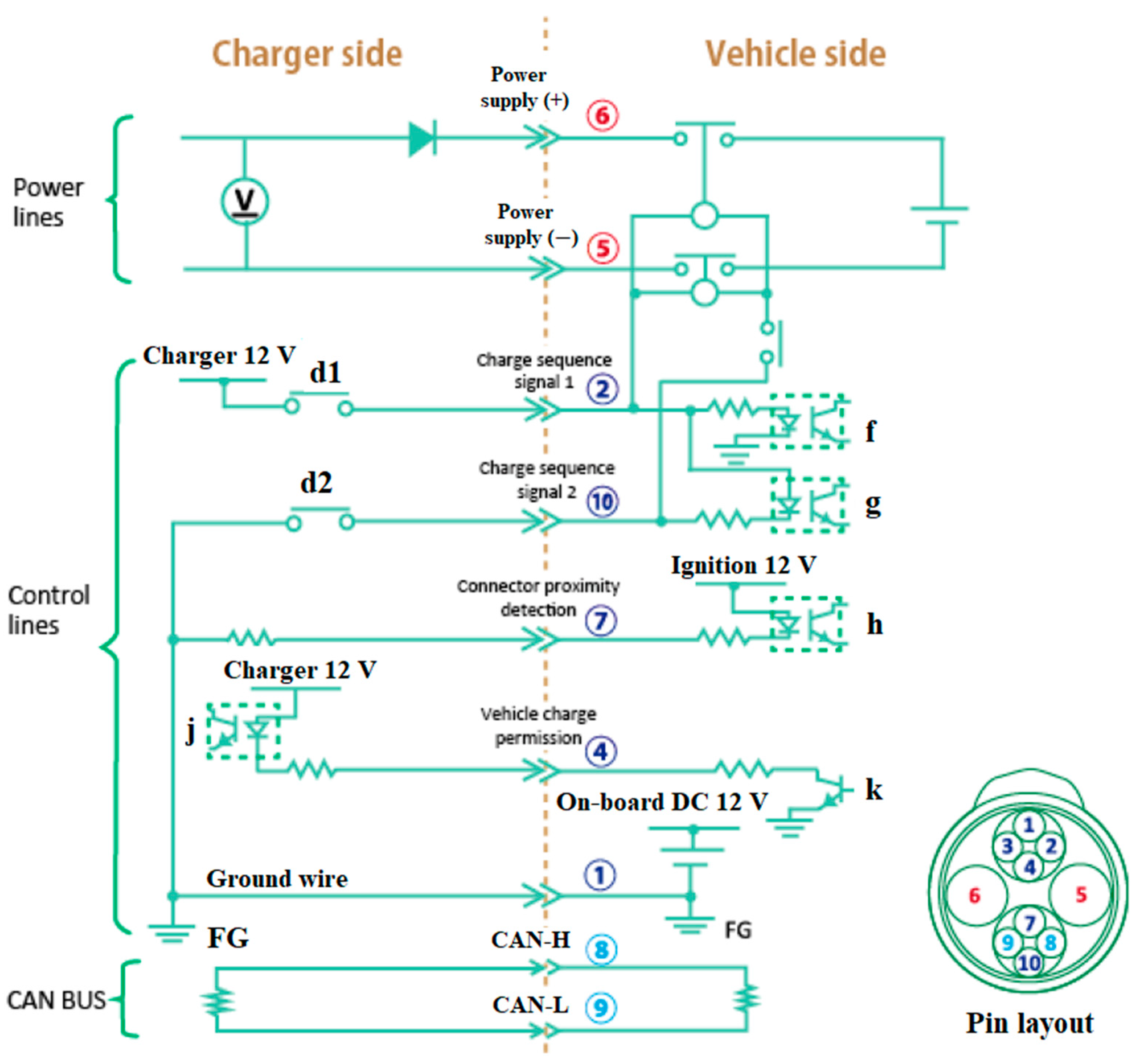
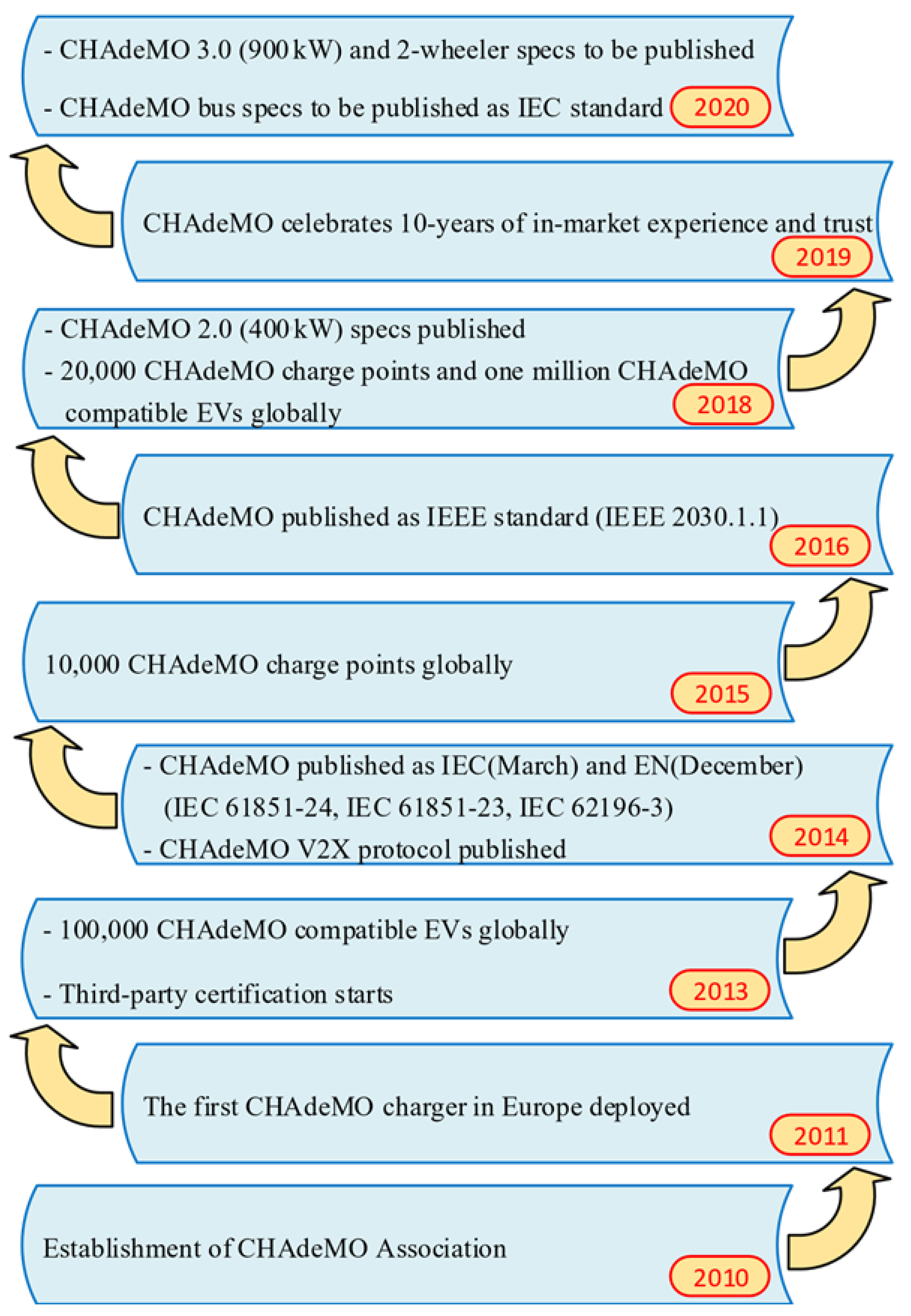
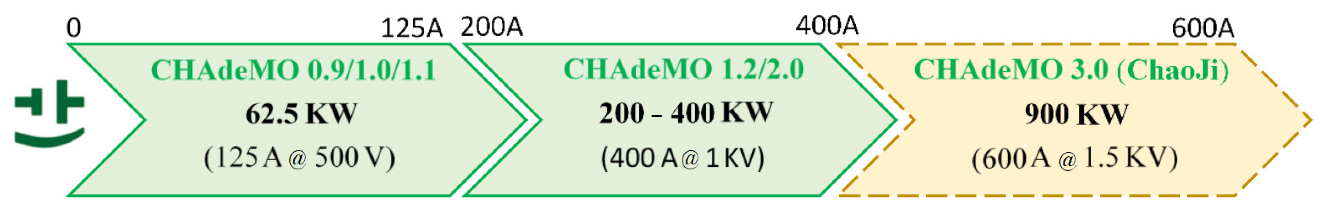
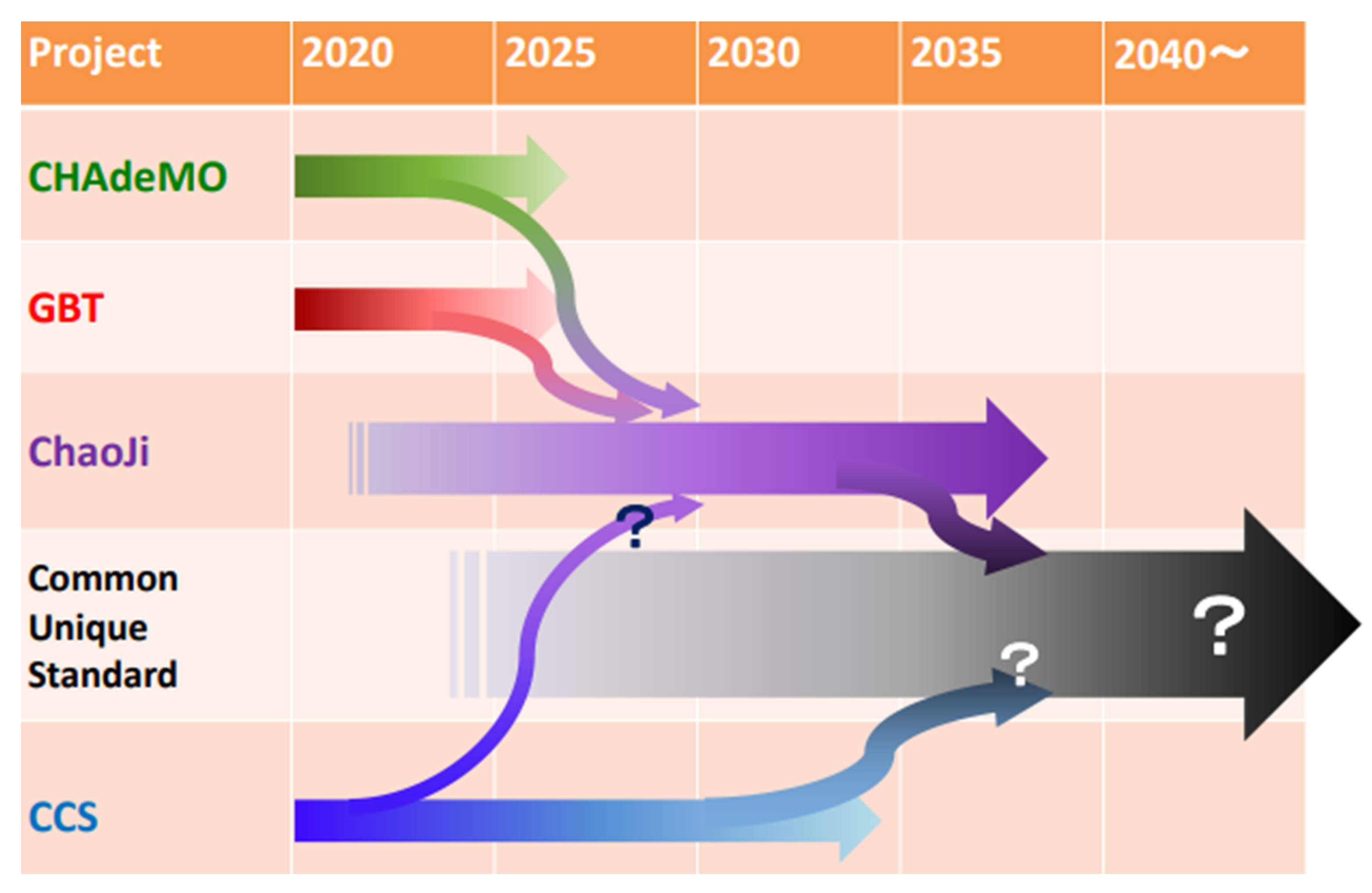
4.4. CHAdeMO Coupler
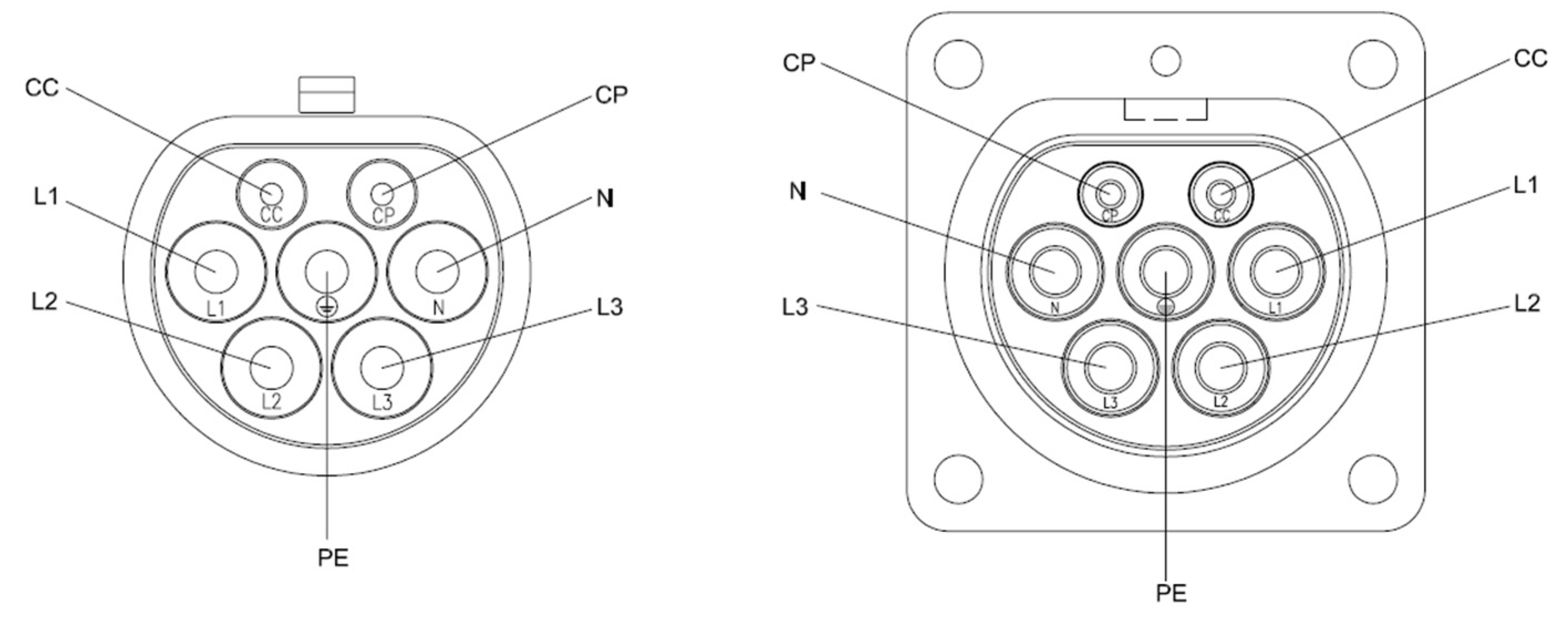
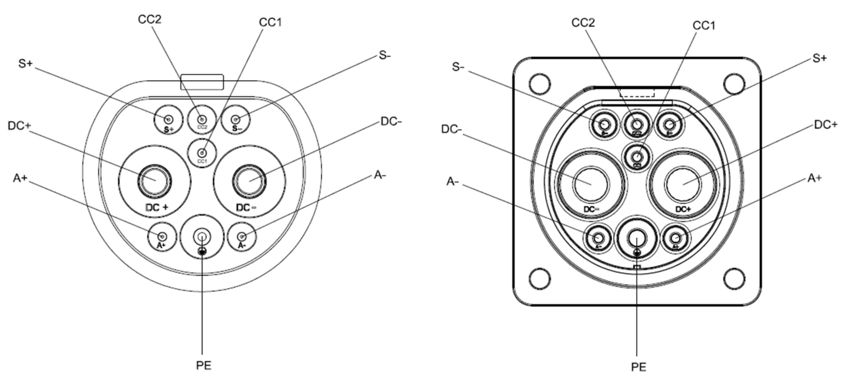
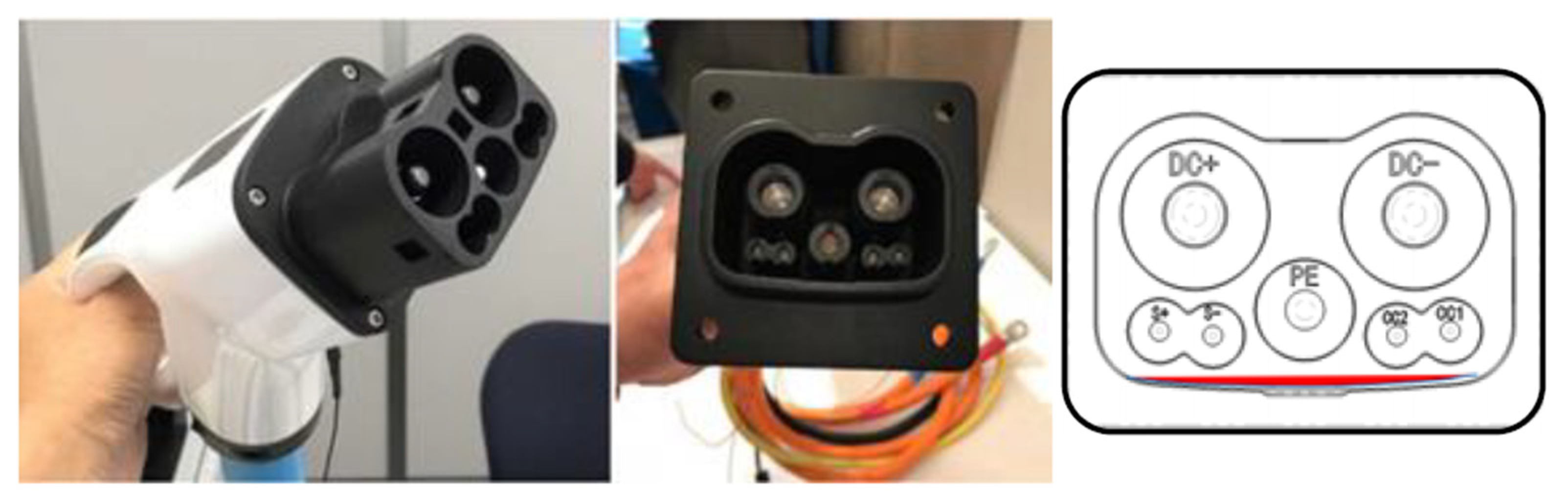
4.5. GB/T Coupler
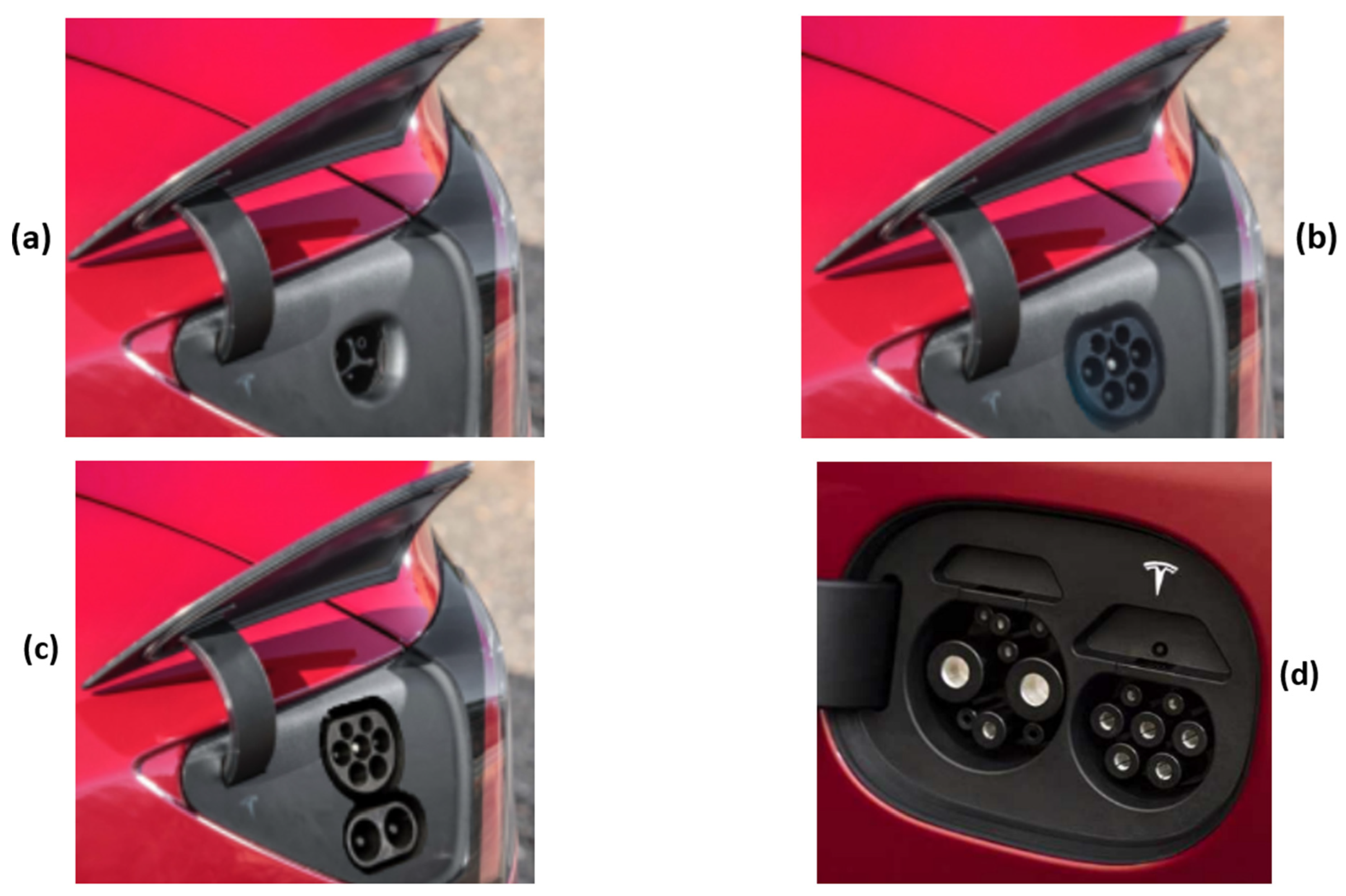
4.6. Tesla Coupler
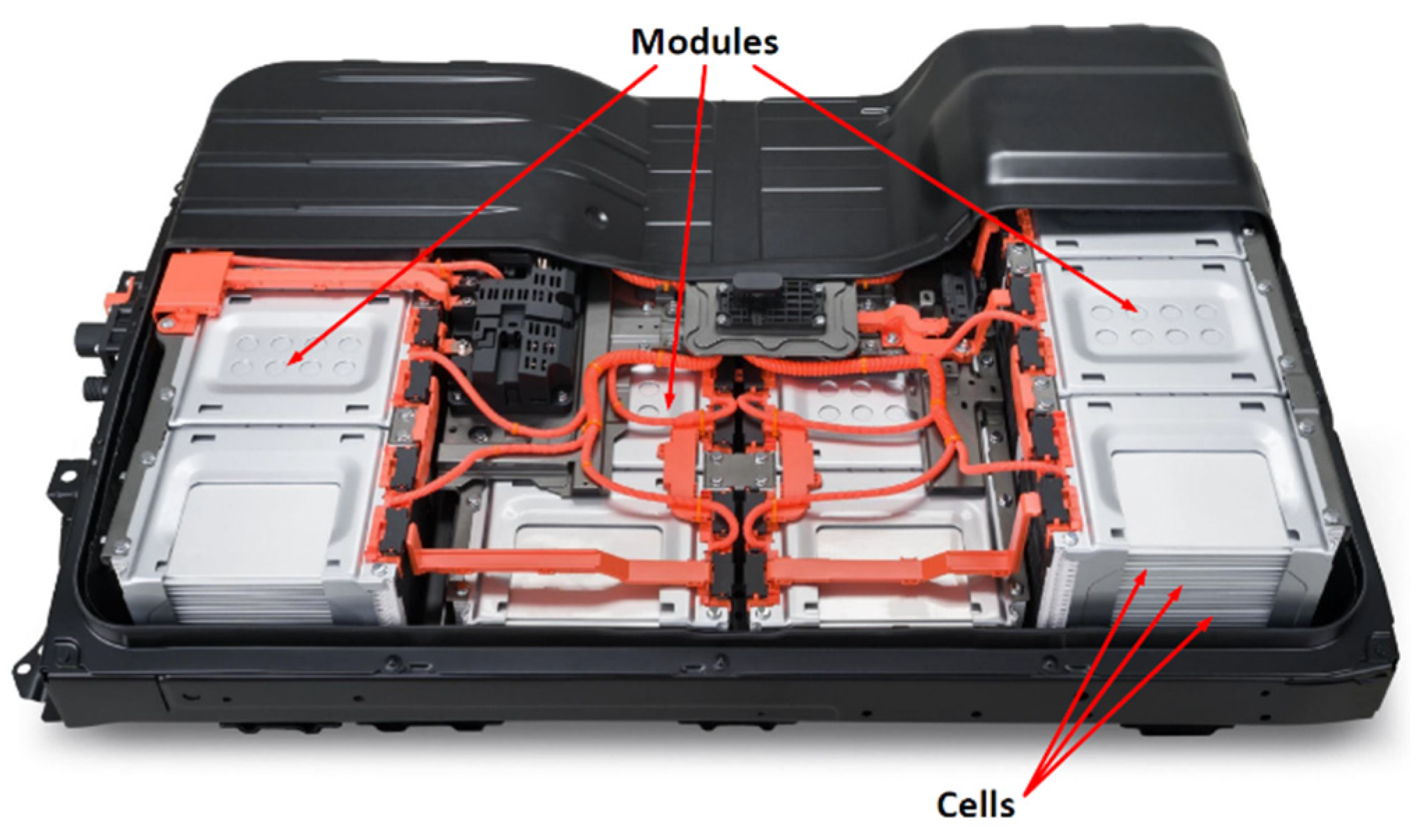
5. EV Batteries
5.1. EV Batteries Classification
5.2. Battery Terminologies
- Rated Voltage: the reference voltage of a cell or battery, sometimes referred to as “Normal” voltage. It is the corresponding voltage at approximately 50% of the battery SOC.
- Cut-off voltage: the low voltage limit of a considered fully discharged battery that varies depending on the battery type and use.
- Open-circuit voltage (OCV) is the battery voltage measured at its terminals when it is not providing any current. The open-circuit voltage depends on the battery SOC and also on temperature.
- Rated Capacity ( (%)): the number of ampere-hours (Ah) that a battery in a single discharge can provide. The total amount of Ah is available when a battery or cell is discharged from 100% SOC to the cut-off voltage under the manufacturer’s conditions. The battery Ah capacity on discharge is determined by several factors: cut-off voltage, discharge current, type and density of electrolyte, design of separators, battery temperature, battery age, battery usage history, number of electrodes, electrode design, and electrode dimensions. We can also quantify battery capacity in terms of Wh (or kWh) [125]. The rated capacity (Wh) is given in Equation (1)
- State of Charge (SOC (%)) is expressed as the percentage of the battery’s current capacity compared to its total capacity. Its equivalent in fuel-powered vehicles is the fuel gauge. As illustrated in Equation (2), SOC is commonly estimated by integrating the battery current to quantify the change in the battery capacity over time [128].with: is the battery current, is the battery-rated capacity (Ah), and SOC () is the SOC initial value.
- Depth of discharge (DOD) is the percentage of capacity depleted from a fully charged battery. It is calculated by dividing the capacity discharged from a fully charged battery by the rated capacity. As seen in Equation (3), the battery depth of discharge is the complement of its SOC (i.e., as one rises, the other falls) [129,130].
- Internal resistance is the total equivalent resistance within the battery, referring to the ohmic contributions of its many components (collector resistance, electrolyte conductivity, etc.). This resistance depends on the battery SOC and may vary with the temperature. In addition, its value differs depending on whether the battery is being charged or discharged. It’s commonly referred to as equivalent series resistance (ESR).
- State of Health (SOH) is the maximum available battery charge ratio to its rated capacity. Therefore, the state of health is an essential indicator for evaluating the battery’s remaining lifespan and determining the degree of its performance decline. It can be expressed as follows [131].
- Cycle Life is the total number of charge/discharge cycles that a battery can tolerate before its capacity is considerably diminished. This feature varies with battery type and is strongly affected by discharging depth, charging method, and battery temperature. It should be noted that discharging a battery underneath its cut-off voltage can considerably reduce its lifespan [132].
5.3. Charging Strategies for EV Batteries
- Constant Voltage (CV) is a battery charging method that allows a battery to be charged by maintaining a constant voltage between its terminals. In contrast, the battery current decreases slowly to zero. Given its simplicity of implementation, this charging method is used for all battery types. However, its drawback is the high current absorbed at the beginning of the battery charging operation, which may be controlled by reducing the CV value.
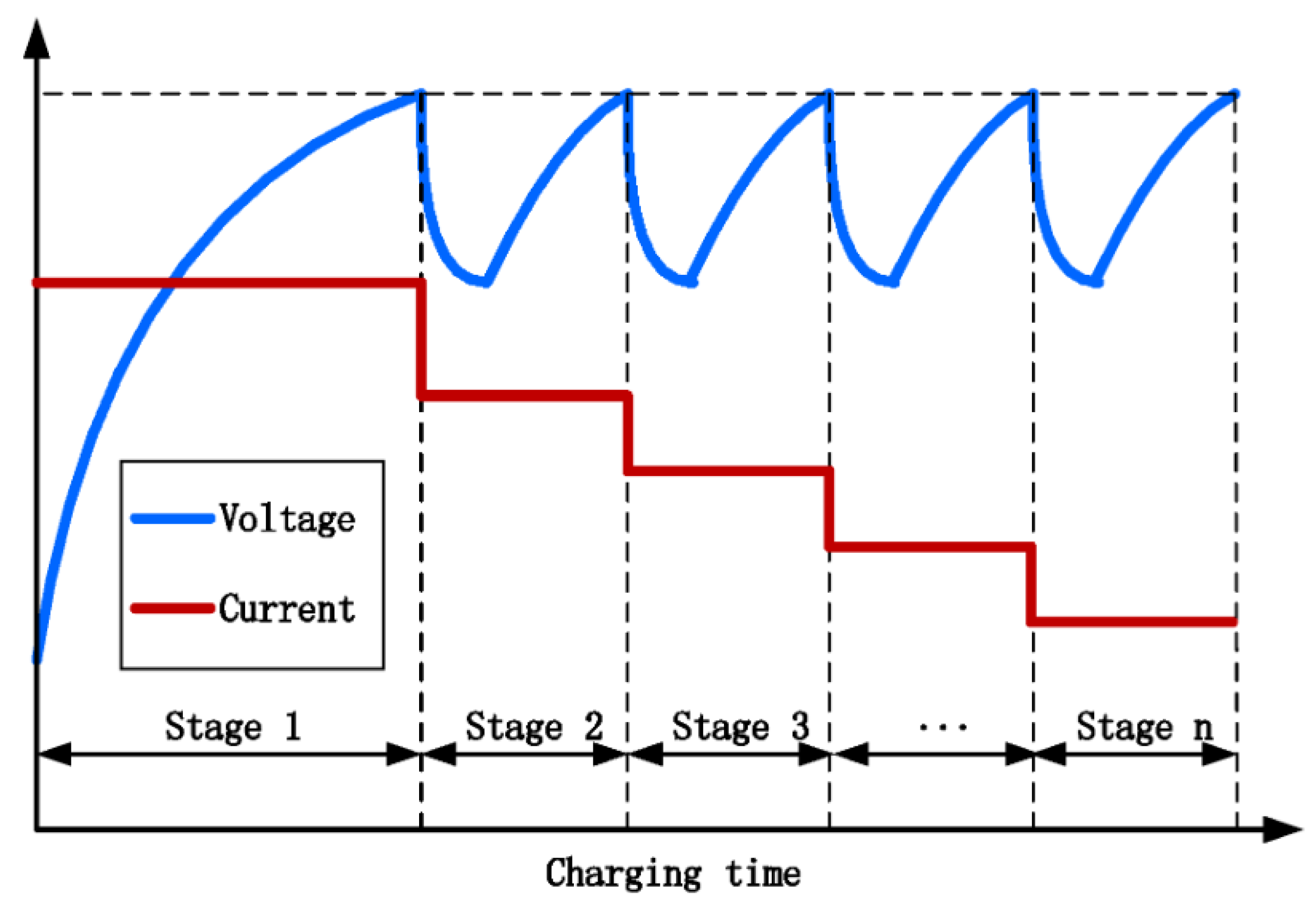
- Constant Current (CC) is a charging/discharging strategy for EV batteries. It consists of maintaining the battery’s current constant with a fixed C-rate while the battery voltage is increasing until the battery voltage reaches its maximum charge value. Then, the process is ended [43].
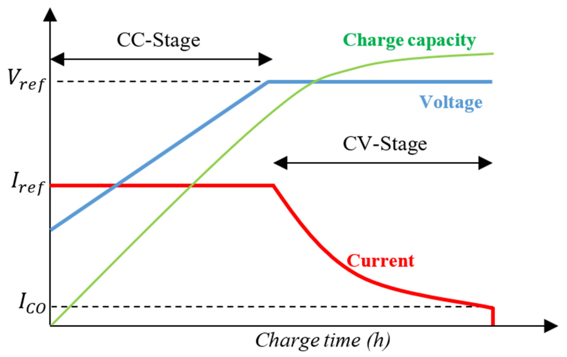
- Constant Current–Constant Voltage (CC-CV) is a dual-stage charging strategy for batteries. It has two phases: a CC Stage and a CV Stage, as depicted in Figure 30. During the first one, the battery is charged with a constant current (usually between 0.5C and 1C in the case of Li-ion battery) until the voltage battery reaches the full charge voltage . In the second one, the battery voltage is kept constant until the current decreases to the cut-off current (), which is usually 0.1C or 0.05C [139].
6. Conclusions
Author Contributions
Funding
Data Availability Statement
Conflicts of Interest
Abbreviations
| AC | Alternating Current |
| BEV(s) | Battery Electric Vehicle(s) |
| CC | Constant Current |
| CCS | Combined Charging System |
| CHAdeMO | CHArge de MOve |
| CV | Constant Voltage |
| DC | Direct Current |
| EV(s) | Electric Vehicle(s) |
| EVSE(s) | Electric Vehicle Supply Equipment(s) |
| G2V | Grid-to-Vehicle |
| GB/T | Guo Biao/Tu¯ıjiàn (Recommended) |
| IEC | International Electrotechnical Commission |
| PHEV | Plug-in Hybrid Electric Vehicle |
| SAE | Society of Automotive Engineers |
| SOC | State of Charge |
| V2G | Vehicle-to-Grid |
| V2H | Vehicle-to-Home |
| V2X | Vehicle-to-Everything |
References
- Rietmann, N.; Hügler, B.; Lieven, T. Forecasting the Trajectory of Electric Vehicle Sales and the Consequences for Worldwide CO2 Emissions. J. Clean. Prod. 2020, 261, 121038. [Google Scholar] [CrossRef]
- Teixeira, A.C.R.; Sodré, J.R. Impacts of Replacement of Engine Powered Vehicles by Electric Vehicles on Energy Consumption and CO2 Emissions. Transp. Res. Part D Transp. Environ. 2018, 59, 375–384. [Google Scholar] [CrossRef]
- Rachid, A.; EL Fadil, H.; Belhaj, F.Z.; Gaouzi, K.; Giri, F. Lyapunov-Based Control of Single-Phase AC–DC Power Converter for BEV Charger. In Recent Advances in Electrical and Information Technologies for Sustainable Development; El Hani, S., Essaaidi, M., Eds.; Advances in Science, Technology & Innovation; Springer International Publishing: Cham, Switzerland, 2019; pp. 115–121. ISBN 978-3-030-05276-8. [Google Scholar]
- International Energy Agency Global EV Outlook 2019: Scaling-up the Transition to Electric Mobility; OECD: Paris, France, 2019; ISBN 978-92-64-47013-2.
- Agrawal, M.; Rajapatel, M.S. Global Perspective on Electric Vehicle 2020. Int. J. Eng. Res. Technol. 2020, 9. [Google Scholar] [CrossRef]
- Gradinaru, G.; Marin, E.; Neagoe, I.; Rotaru, C. The Impact of Technological Evolution in the Automotive Industry on How to Manifest the Rebound Effect. In Proceedings of the 63rd International Scientific Conference on Economic and Social Development—Building Resilient Society, Zagreb, Croatia, 11–12 December 2020; pp. 179–185. [Google Scholar]
- International Energy Agency Global EV Outlook 2020: Entering the Decade of Electric Drive? OCED: Paris, France, 2020; p. 276.
- Burilovic, L.; Rados, T.; Recker, N. Economic and Social Development: 63rd International Scientific Conference on Economic and Social Development—“Building Resilient Society”: Book of Proceedings, Zagreb, Croatia, 11–12 December 2020; Varazdin Development and Entrepreneurship Agency: Varazdin, Croatia, 2020; ISBN 978-1-74351-613-3. [Google Scholar]
- International Energy Agency Global EV Outlook 2021: Accelerating Ambitions despite the Pandemic; OCED: Paris, France, 2021; p. 101.
- Jamie Morgan Electric Vehicles: The Future We Made and the Problem of Unmaking It. Camb. J. Econ. 2020, 44, 953–977. [CrossRef]
- Jones, L.; Lucas-Healey, K.; Sturmberg, B.; Temby, H.; Islam, M. A Comprehensive Analysis of Vehicle-to-Grid Technology Worldwide. Realis. Electr. Veh. Grid Serv. Proj. 2021, 169. [Google Scholar]
- Roland Irle Global EV Sales for 2021. Available online: https://www.ev-volumes.com/country/total-world-plug-in-vehicle-volumes/ (accessed on 25 July 2022).
- International Energy Agency Global EV Outlook 2022: Securing Supplies for an Electric Future; OCED: Paris, France, 2022; p. 221.
- European Automobile Manufacturers Association (ACEA) New Vehicles in the EU by Fuel Type: Market Share from 2018 to 2021. 2022. Available online: https://www.acea.auto/files/fuel-types-of-new-passenger-cars-in-eu-2022-1024x576.png (accessed on 22 July 2022).
- European Automobile Manufacturers Association (ACEA) New Passenger Car Registrations by Fuel Type in the European Union 2020. Available online: https://www.acea.be/uploads/press_releases_files/20190206_PRPC_fuel_Q4_2019_FINAL.pdf (accessed on 17 May 2022).
- European Automobile Manufacturers Association (ACEA). Vehicles in Use, Europe 2022; European Automobile Manufacturers’ Association: Brussels, Belgium, 2022; p. 21. [Google Scholar]
- Florian, R. Optimized Charging of Lithium-Ion Batteries with Physico-Chemical Models. Master Thesis, RWTH Aachen University, Aachen, Germany, 2021. Available online: https://d-nb.info/1248307852/34 (accessed on 27 July 2022).
- Gür, T.M. Review of Electrical Energy Storage Technologies, Materials and Systems: Challenges and Prospects for Large-Scale Grid Storage. Energy Environ. Sci. 2018, 11, 2696–2767. [Google Scholar] [CrossRef]
- Rachid, A.; Fadil, H.E.; Koundi, M.; Idrissi, Z.E.; Tahri, A.; Giri, F.; Guerrero, J.M. PQ Theory-Based Control of Single-Stage V2G Three-Phase BEV Charger for High-Voltage Battery. IFAC-Pap. 2019, 52, 73–78. [Google Scholar] [CrossRef]
- Rachid, A.; Fadil, H.E.; Belhaj, F.Z.; Gaouzi, K.; Giri, F. Lyapunov-Based Control of Single-Phase AC-DC Power Converter for BEV Charger. In Proceedings of the 2017 International Conference on Electrical and Information Technologies (ICEIT), Rabat, Morocco, 15–18 November 2017; pp. 1–5. [Google Scholar]
- Van Mierlo, J.; Berecibar, M.; El Baghdadi, M.; De Cauwer, C.; Messagie, M.; Coosemans, T.; Jacobs, V.A.; Hegazy, O. Beyond the State of the Art of Electric Vehicles: A Fact-Based Paper of the Current and Prospective Electric Vehicle Technologies. World Electr. Veh. J. 2021, 12, 20. [Google Scholar] [CrossRef]
- Monteiro, V.; Gonçalves, H.; Ferreira, J.C.; Afonso, J.L. Batteries Charging Systems for Electric and Plug-In Hybrid Electric Vehicles; IntechOpen: London, UK, 2012; ISBN 978-953-51-0698-2. [Google Scholar]
- Rachid, A.; EL Fadil, H.; Lassioui, A.; Giri, F. Advanced Control of Bidirectional Three-Phase BEV Charger with V2X Technology. Int. J. Model. Identif. Control 2019, 33, 344–357. [Google Scholar] [CrossRef]
- Islam, S.; Iqbal, A.; Marzband, M.; Khan, I.; Al-Wahedi, A.M.A.B. State-of-the-Art Vehicle-to-Everything Mode of Operation of Electric Vehicles and Its Future Perspectives. Renew. Sustain. Energy Rev. 2022, 166, 112574. [Google Scholar] [CrossRef]
- Monteiro, V.; Pinto, J.G.; Afonso, J.L. Operation Modes for the Electric Vehicle in Smart Grids and Smart Homes: Present and Proposed Modes. IEEE Trans. Veh. Technol. 2016, 65, 1007–1020. [Google Scholar] [CrossRef]
- Garrido, P.; Soares, F.; Moreira, A.P. (Eds.) CONTROLO 2016: Proceedings of the 12th Portuguese Conference on Automatic Control; Lecture Notes in Electrical Engineering; Springer International Publishing: Cham, Switzerland, 2017; Volume 402, ISBN 978-3-319-43670-8. [Google Scholar]
- Solanke, T.U.; Ramachandaramurthy, V.K.; Yong, J.Y.; Pasupuleti, J.; Kasinathan, P.; Rajagopalan, A. A Review of Strategic Charging–Discharging Control of Grid-Connected Electric Vehicles. J. Energy Storage 2020, 28, 101193. [Google Scholar] [CrossRef]
- Pearre, N.S.; Ribberink, H. Review of Research on V2X Technologies, Strategies, and Operations. Renew. Sustain. Energy Rev. 2019, 105, 61–70. [Google Scholar] [CrossRef]
- Thompson, A.W.; Perez, Y. Vehicle-to-Everything (V2X) Energy Services, Value Streams, and Regulatory Policy Implications. Energy Policy 2020, 137, 111136. [Google Scholar] [CrossRef]
- Kisacikoglu, M.C. Vehicle-to-Grid (V2G) Reactive Power Operation Analysis of the EV/PHEV Bidirectional Battery Charger. Ph.D. Thesis, University of Tennessee, Knoxville, TN, USA, 2013. [Google Scholar]
- Xiao, X.; Molin, H.; Kourtza, P.; Collin, A.; Harrison, G.; Djokic, S.; Meyer, J.; Müller, S.; Möller, F. Component-Based Modelling of EV Battery Chargers. In Proceedings of the 2015 IEEE Eindhoven PowerTech, Eindhoven, The Netherlands, 29 June–2 July 2015; pp. 1–6. [Google Scholar]
- Ronanki, D.; Kelkar, A.; Williamson, S.S. Extreme Fast Charging Technology—Prospects to Enhance Sustainable Electric Transportation. Energies 2019, 12, 3721. [Google Scholar] [CrossRef]
- Kumar, P.; Nikolovski, S.; Dong, Z.Y. (Eds.) Internet of Energy Handbook, 1st ed.; CRC Press: Boca Raton, FL, USA, 2021; ISBN 978-0-367-49964-8. [Google Scholar]
- Rachid, A.; Fadil, H.E.; Rachid, K.; Lassioui, A.; Idrissi, Z.E. H-Infinity Control of Bidirectional Dc-Dc Power Converter for V2G BEV Charger. In Proceedings of the 2020 International Symposium on Advanced Electrical and Communication Technologies (ISAECT), Marrakech, Morocco, 25–27 November 2020; pp. 1–6. [Google Scholar]
- Sousa, T.J.C.; Pedrosa, D.; Monteiro, V.; Afonso, J.L. A Review on Integrated Battery Chargers for Electric Vehicles. Energies 2022, 15, 2756. [Google Scholar] [CrossRef]
- Lebrouhi, B.E.; Khattari, Y.; Lamrani, B.; Maaroufi, M.; Zeraouli, Y.; Kousksou, T. Key Challenges for a Large-Scale Development of Battery Electric Vehicles: A Comprehensive Review. J. Energy Storage 2021, 44, 103273. [Google Scholar] [CrossRef]
- Rubino, L.; Capasso, C.; Veneri, O. Review on Plug-in Electric Vehicle Charging Architectures Integrated with Distributed Energy Sources for Sustainable Mobility. Appl. Energy 2017, 207, 438–464. [Google Scholar] [CrossRef]
- Mohamed, A.A.S.; Shaier, A.A.; Metwally, H.; Selem, S.I. A Comprehensive Overview of Inductive Pad in Electric Vehicles Stationary Charging. Appl. Energy 2020, 262, 114584. [Google Scholar] [CrossRef]
- Lassioui, A.; Fadil, H.E.; Rachid, A.; El-Idrissi, Z.; Bouanou, T.; Belhaj, F.Z.; Giri, F. Modelling and Sliding Mode Control of a Wireless Power Transfer System for BEV Charger. Int. J. Model. Identif. Control 2020, 34, 171–186. [Google Scholar] [CrossRef]
- Amjad, M.; Farooq-i-Azam, M.; Ni, Q.; Dong, M.; Ansari, E.A. Wireless Charging Systems for Electric Vehicles. Renew. Sustain. Energy Rev. 2022, 167, 112730. [Google Scholar] [CrossRef]
- Lassioui, A.; Fadil, H.E.; Rachid, A.; Belhaj, F.Z.; Tarkany, O.; Bajit, A. Characteristics Analysis of Wireless Power Transfer System for Electric Vehicle Charging Applications. In Proceedings of the 2018 International Symposium on Advanced Electrical and Communication Technologies (ISAECT), Rabat, Morocco, 21–23 November 2018; pp. 1–6. [Google Scholar]
- Lassioui, A.; El Fadil, H.; Belhaj, F.Z.; Rachid, A. Battery Charger for Electric Vehicles Based ICPT and CPT—A State of the Art. In Proceedings of the 2018 Renewable Energies, Power Systems & Green Inclusive Economy (REPS-GIE), Casablanca, Morocco, 23–24 April 2018; pp. 1–6. [Google Scholar]
- Hemavathi, S.; Shinisha, A. A Study on Trends and Developments in Electric Vehicle Charging Technologies. J. Energy Storage 2022, 52, 105013. [Google Scholar] [CrossRef]
- Safayatullah, M.; Elrais, M.T.; Ghosh, S.; Rezaii, R.; Batarseh, I. A Comprehensive Review of Power Converter Topologies and Control Methods for Electric Vehicle Fast Charging Applications. IEEE Access 2022, 10, 40753–40793. [Google Scholar] [CrossRef]
- Haghbin, S.; Lundmark, S.; Alakula, M.; Carlson, O. Grid-Connected Integrated Battery Chargers in Vehicle Applications: Review and New Solution. IEEE Trans. Ind. Electron. 2013, 60, 459–473. [Google Scholar] [CrossRef]
- Mahmud, K.; Town, G.E.; Morsalin, S.; Hossain, M.J. Integration of Electric Vehicles and Management in the Internet of Energy. Renew. Sustain. Energy Rev. 2018, 82, 4179–4203. [Google Scholar] [CrossRef]
- Yilmaz, M.; Krein, P.T. Review of Battery Charger Topologies, Charging Power Levels, and Infrastructure for Plug-In Electric and Hybrid Vehicles. IEEE Trans. Power Electron. 2013, 28, 2151–2169. [Google Scholar] [CrossRef]
- Chakraborty, S.; Vu, H.-N.; Hasan, M.M.; Tran, D.-D.; Baghdadi, M.E.; Hegazy, O. DC-DC Converter Topologies for Electric Vehicles, Plug-in Hybrid Electric Vehicles and Fast Charging Stations: State of the Art and Future Trends. Energies 2019, 12, 1569. [Google Scholar] [CrossRef]
- Tan, K.M.; Ramachandaramurthy, V.K.; Yong, J.Y. Latest Electric Vehicle Charging Technology for Smart Grid Application. In Proceedings of the 2018 IEEE 7th International Conference on Power and Energy (PECon), Kuala Lumpur, Malaysia, 3–4 December 2018; pp. 366–371. [Google Scholar]
- Monteiro, V.; Afonso, J.A.; Sousa, T.J.C.; Cardoso, L.L.; Pinto, J.G.; Afonso, J.L. Vehicle Electrification: Technologies, Challenges, and a Global Perspective for Smart Grids. In Innovation in Energy Systems; Ustun, T.S., Ed.; IntechOpen: Rijeka, Croatia, 2019. [Google Scholar]
- Mutarraf, M.U.; Guan, Y.; Xu, L.; Su, C.-L.; Vasquez, J.C.; Guerrero, J.M. Electric Cars, Ships, and Their Charging Infrastructure—A Comprehensive Review. Sustain. Energy Technol. Assess. 2022, 52, 102177. [Google Scholar] [CrossRef]
- Ahmed, I.; Adil, H.M.M.; Ahmed, S.; Ahmad, I.; Rehman, Z. Robust Nonlinear Control of Battery Electric Vehicle Charger in Grid to Vehicle and Vehicle to Grid Applications. J. Energy Storage 2022, 52, 104813. [Google Scholar] [CrossRef]
- Rachid, A.; El Fadil, H.; Giri, F.; Lassioui, A. Nonlinear Output Feedback Control of V2G Single-Phase on-Board BEV Charger. Asian J. Control 2020, 22, 1848–1859. [Google Scholar] [CrossRef]
- Rachid, A.; Fadil, H.E.; Giri, F. Dual Stage CC-CV Charge Method for Controlling DC-DC Power Converter in BEV Charger. In Proceedings of the 2018 19th IEEE Mediterranean Electrotechnical Conference (MELECON), Marrakech, Morocco, 2–7 May 2018; pp. 74–79. [Google Scholar]
- Veneri, O. (Ed.) Technologies and Applications for Smart Charging of Electric and Plug-in Hybrid Vehicles; Springer International Publishing: Cham, Switzerland, 2017; ISBN 978-3-319-43649-4. [Google Scholar]
- Rachid, K.; EL Fadil, H.; Rachid, A.; Bouanou, T.; Gaouzi, K.; Belhaj, F.Z. Nonlinear Output Feedback Control of Bidirectional Dc-Dc Power Converter for V2X BEV Charger: Theoretical Analysis and Experimental Results. In Proceedings of the International Symposium on Advanced Electrical and Communication Technologies (ISAECT2020), Kenitra, Morocco, 25–27 November 2020; pp. 1–6. [Google Scholar]
- Ashfaq, M.; Butt, O.; Selvaraj, J.; Rahim, N. Assessment of Electric Vehicle Charging Infrastructure and Its Impact on the Electric Grid: A Review. Int. J. Green Energy 2021, 18, 657–686. [Google Scholar] [CrossRef]
- Sayed, K.; Gabbar, H. Electric Vehicle to Power Grid Integration Using Three-Level AC/DC Converter and PI-Fuzzy Controller. Energies 2016, 9, 532. [Google Scholar] [CrossRef]
- Tahir, M. Electric Vehicles and Vehicle-to-Grid Technology. Master’s Thesis, The Arctic University of Norway, Tromsø, Norway, 2017. [Google Scholar]
- Grbović, P. Interface DC–DC Converters. In Ultra-Capacitors in Power Conversion Systems; John Wiley & Sons, Ltd.: Hoboken, NJ, USA, 2013; pp. 216–315. ISBN 978-1-118-69363-6. [Google Scholar]
- Kissaoui, M.; Abouloifa, A.; Abouelmahjoub, Y.; Chaoui, F.Z.; Giri, F. Output-Feedback Nonlinear Adaptive Control of Single-Phase Half-Bridge Ups Systems. Asian J. Control 2016, 18, 1995–2009. [Google Scholar] [CrossRef]
- Monteiro, V.; Catalao, J.; Sousa, T.; Pinto, J.; Mezaroba, M.; Afonso, J. Improved Voltage Control for the Electric Vehicle Operation in V2H Mode as an Off-Line UPS in the Context of Smart Homes. EAI Endorsed Trans. Energy Web 2020, 7, 160980. [Google Scholar] [CrossRef][Green Version]
- Monteiro, V.; Ferreira, J.C.; Nogueiras Meléndez, A.A.; Couto, C.; Afonso, J.L. Experimental Validation of a Novel Architecture Based on a Dual-Stage Converter for Off-Board Fast Battery Chargers of Electric Vehicles. IEEE Trans. Veh. Technol. 2018, 67, 1000–1011. [Google Scholar] [CrossRef]
- Restrepo, M.; Morris, J.; Kazerani, M.; Cañizares, C.A. Modeling and Testing of a Bidirectional Smart Charger for Distribution System EV Integration. IEEE Trans. Smart Grid 2018, 9, 152–162. [Google Scholar] [CrossRef]
- SAE International J1772_201710: SAE Electric Vehicle and Plug in Hybrid Electric Vehicle Conductive Charge Coupler—SAE International. Available online: https://www.sae.org/standards/content/j1772_201710/ (accessed on 26 July 2022).
- Ahmad, A.; Khan, Z.A.; Saad Alam, M.; Khateeb, S. A Review of the Electric Vehicle Charging Techniques, Standards, Progression and Evolution of EV Technologies in Germany. Smart Sci. 2018, 6, 36–53. [Google Scholar] [CrossRef]
- Das, H.S.; Rahman, M.M.; Li, S.; Tan, C.W. Electric Vehicles Standards, Charging Infrastructure, and Impact on Grid Integration: A Technological Review. Renew. Sustain. Energy Rev. 2020, 120, 109618. [Google Scholar] [CrossRef]
- Osório, G.J.; Gough, M.; Lotfi, M.; Santos, S.F.; Espassandim, H.M.D.; Shafie-khah, M.; Catalão, J.P.S. Rooftop Photovoltaic Parking Lots to Support Electric Vehicles Charging: A Comprehensive Survey. Int. J. Electr. Power Energy Syst. 2021, 133, 107274. [Google Scholar] [CrossRef]
- Zhang, T. Smart Electric Vehicle Charging: Mitigating Supply-Demand Disparity Through User Incentives—ProQuest. Ph.D. Thesis, University of California, Los Angeles, CA, USA, 2018. [Google Scholar]
- Ayob, A.; Mohd Faizal Wan Mahmood, W.; Mohamed, A.; Zamri Che Wanik, M.; Mohd Siam, M.; Sulaiman, S.; Hanifah Azit, A.; Azrin Mohamed Ali, M. Review on Electric Vehicle, Battery Charger, Charging Station and Standards. RJASET 2014, 7, 364–373. [Google Scholar] [CrossRef]
- SAE International J1772_201001: SAE Electric Vehicle and Plug in Hybrid Electric Vehicle Conductive Charge Coupler—SAE International. Available online: https://www.sae.org/standards/content/j1772_201001/ (accessed on 26 July 2022).
- Paulraj, P. Charging Basics 102: Electric Vehicle Charging Levels, Modes and Types Explained | North America vs. Europe Charging Cables and Plug Types. E-Mobility Simplified|Basics of Electric Vehicles and Charging 2019. Available online: https://www.emobilitysimplified.com/2019/10/ev-charging-levels-modes-types-explained.html (accessed on 27 July 2022).
- Wikipedia, The Free Encyclopedia. Wikipedia contributors SAE J1772. 2020. Available online: https://en.wikipedia.org/w/index.php?title=SAE_J1772&oldid=965111434 (accessed on 26 July 2022).
- Yong, J.Y.; Ramachandaramurthy, V.K.; Tan, K.M.; Mithulananthan, N. A Review on the State-of-the-Art Technologies of Electric Vehicle, Its Impacts and Prospects. Renew. Sustain. Energy Rev. 2015, 49, 365–385. [Google Scholar] [CrossRef]
- Saldaña, G.; San Martin, J.I.; Zamora, I.; Asensio, F.J.; Oñederra, O. Electric Vehicle into the Grid: Charging Methodologies Aimed at Providing Ancillary Services Considering Battery Degradation. Energies 2019, 12, 2443. [Google Scholar] [CrossRef]
- WeberAuto. There Is No Such Thing as a Level 3 EV Charger. 2019. Available online: https://www.youtube.com/watch?v=jZBsOud4O9Q (accessed on 31 May 2022).
- Hanauer, D. Mode 2 Charging—Testing and Certification for International Market Access. World Electr. Veh. J. 2018, 9, 26. [Google Scholar] [CrossRef]
- International Electrotechnical Commission IEC 61851-1:2017: Electric Vehicle Conductive Charging System—Part 1: General Requirements 2017. Available online: https://webstore.iec.ch/publication/33644 (accessed on 26 July 2022).
- Triviño, A.; González-González, J.M.; Aguado, J.A. Wireless Power Transfer Technologies Applied to Electric Vehicles: A Review. Energies 2021, 14, 1547. [Google Scholar] [CrossRef]
- GB China National Standards. Available online: http://www.gbstandards.org/ (accessed on 28 July 2022).
- David Herron Types of Electric Car Charging Connectors, and Compatibility: A Field Guide to Electric Vehicle Service Equipment. Available online: https://greentransportation.info/ev-charging/range-confidence/chap4-charging/4-evse-field-guide.html (accessed on 26 July 2022).
- Hackaday. Lewin Day EV Charging Connectors Come In Many Shapes And Sizes. 2022. Available online: https://hackaday.com/2022/04/28/ev-charging-connectors-come-in-many-shapes-and-sizes/ (accessed on 28 July 2022).
- EVSEPower EV Chargers, Cables and Connectors—EV Charger OEM 2022. Available online: https://evsepower.com/index.php/2022/03/09/ev-chargers-cables-and-connectors/ (accessed on 28 July 2022).
- Leskarac, D.; Panchal, C.; Stegen, S.; Lu, J. PEV Charging Technologies and V2G on Distributed Systems and Utility Interfaces. In Vehicle-to-Grid: Linking Electric Vehicles to the Smart Grid; IET Digital Library, 2015; pp. 157–222. ISBN 978-1-84919-855-4. [Google Scholar]
- Enel X Way The Different EV Charging Connector Types. Available online: https://evcharging.enelx.com/resources/blog/552-ev-charging-connector-types (accessed on 26 July 2022).
- Hicks, M. English: SAE J1772 Plug (Cropped from the Original Photo). 2012. Available online: https://commons.wikimedia.org/wiki/File:SAE_J1772_7058855567.jpg (accessed on 26 July 2022).
- Mliu92 English: Signaling Circuit for the SAE J1772 Standard. 2021. Available online: https://commons.wikimedia.org/wiki/File:J1772_signaling_circuit.svg (accessed on 26 July 2022).
- Recharge électrique. Tom Définition: C’est quoi une prise de recharge Type 2? 2020. Available online: https://www.recharge-electrique.com/definition-prise-recharge-electrique-type-2/ (accessed on 26 July 2022).
- Rivera, S.; Kouro, S.; Vazquez, S.; Goetz, S.M.; Lizana, R.; Romero-Cadaval, E. Electric Vehicle Charging Infrastructure: From Grid to Battery. IEEE Ind. Electron. Mag. 2021, 15, 37–51. [Google Scholar] [CrossRef]
- Wikipedia, The Free Encyclopedia. Wikipedia contributors Type 2 Connector. 2020. Available online: https://en.wikipedia.org/w/index.php?title=Type_2_connector&oldid=943696021 (accessed on 16 July 2022).
- Kirchhundem MENNEKES-My Power Connection: The Small Charging in between—Safe Charging with the Right Charging Cable for Mode 2. Available online: http://www.mennek.es/index.php?id=latest0&tx_ttnews[tt_news]=882&cHash=79259062694ccc973ecb1856dc6cab4c (accessed on 26 July 2022).
- Haidar, B. A Techno-Economic Analysis of the Electric Vehicle Transition: Policy, Infrastructure, Usage, and Design. Ph.D. Thesis, Université Paris-Saclay, Paris, France, 2021. [Google Scholar]
- National Academies of Sciences, Engineering, and Medicine. Assessment of Technologies for Improving Light-Duty Vehicle Fuel Economy—2025–2035; The National Academies Press: Washington, DC, USA, 2021; ISBN 978-0-309-37122-3. [Google Scholar]
- John, D. Kelly SAE J1772 DC Level 2 Coupler CCS (Combination Charge System (CCS) Type 1 Charge Receptacle). 2019. Available online: https://weberstate.app.box.com/s/wcksjm6j80ubrqdqkqr8sy8o6vhlgr0t (accessed on 26 July 2022).
- Ajzh2074 Español: Conector CCS Combinado Tipo 2 Según Estándar IEC 62196. Llamado También Combo2. Usado En Europa Para La Recarga de Vehículos Eléctricos Como El BWW I3, VW e-up!, VW e-Golf y GM Spark EV. 2014. Available online: https://commons.wikimedia.org/wiki/File:CCSCombo2.svg (accessed on 26 July 2022).
- Aitor Ubierna (ITE). Samuel Sánchez (ITE) D8.2 WiseGRID FastV2G and Other Innovative Optimized Storage Solutions 2018. Available online: https://cdn.nimbu.io/s/76bdjzc/channelentries/8qd2nl6/files/D8.2_WiseGRID_FastV2G_Design.pdf?aopz8sn (accessed on 26 July 2022).
- CHAdeMO Association CHAdeMO Website. Available online: https://www.chademo.com/ (accessed on 26 July 2022).
- CHAdeMO Association CHAdeMO Association & Protocol 2019. Available online: https://www.chademo.com/wp2016/wp-content/uploads/2019/05/2019%20CHAdeMO_Brochure_web.pdf (accessed on 22 July 2022).
- Pat Joint China and Japan ChaoJi EV Project Works towards “CHAdeMO 3.0. Available online: https://midaevse.com:443/news/joint-china-and-japan-chaoji-ev-project-works-towards-chademo-3-0/ (accessed on 26 July 2022).
- Mark Kane CHAdeMO Association Introduces CHAdeMO 3.0 Protocol (ChaoJi). Available online: https://insideevs.com/news/419048/chademo-3-0-released-chaoji/ (accessed on 28 July 2022).
- Dong, L.Y.; Yoshida, M.D. ChaoJi Standard 2020. Available online: https://www.chademo.com/wp2016/wp-content/uploads/ChaoJi202006/ChaoJi_Presenataion_EN.pdf (accessed on 18 July 2022).
- CHAdeMO Association High Power (ChaoJi)|CHAdeMO. Available online: https://www.chademo.com/technology/high-power (accessed on 26 July 2022).
- Standardization Administration Committee of China GB/T 20234.1-2015|Connection Set for Conductive Charging of Electric Vehicles—Part 1: General Requirements. Available online: https://www.chinesestandard.net/PDF.aspx/GBT20234.1-2015 (accessed on 7 August 2022).
- Standardization Administration Committee of China GB/T 20234.2-2015|Connection Set for Conductive Charging of Electric Vehicles—Part 2: AC Charging Coupler. Available online: https://www.chinesestandard.net/Related.aspx/GBT20234.2-2015 (accessed on 26 July 2022).
- Tang, W.W.; Wu, Y.M.; Qin, J. Comparative Study on Electric Vehicle Charging Standards at Home and Abroad. Adv. Mater. Res. 2013, 608–609, 1553–1559. [Google Scholar] [CrossRef]
- Standardization Administration Committee of China GB/T 20234.3-2015|Connection Set for Conductive Charging of Electric Vehicles—Part 3: DC Charging Coupler. Available online: https://www.chinesestandard.net/PDF/English.aspx/GBT20234.3-2015 (accessed on 26 July 2022).
- Jia, L.; Qin, Y.; Liu, B.; Liu, Z.; Diao, L.; An, M. (Eds.) Proceedings of the 4th International Conference on Electrical and Information Technologies for Rail Transportation (EITRT) 2019: Novel Traction Drive Technologies of Rail Transportation; Lecture Notes in Electrical Engineering; Springer: Singapore, 2020; Volume 638, ISBN 9789811528613. [Google Scholar]
- Kane, M. Here Is the Prototype for the New GB/T—CHAdeMO Plug and Inlet. Available online: https://insideevs.com/news/356958/prototype-new-gbt-chademo-plug-inlet/ (accessed on 26 July 2022).
- Berman, B. CHAdeMO 3.0 to Harmonize Global EV Quick Charging Standards. Available online: https://www.sae.org/site/news/2020/05/chademo-3.0-to-harmonize-global-ev-quick-charging-standards (accessed on 29 July 2022).
- Boyd, J. China and Japan Drive a Global EV Charging Effort: The New Standard Will Be Backward Compatible with Select Charging Stations—[News]. IEEE Spectr. 2019, 56, 12–13. [Google Scholar] [CrossRef]
- Wikipedia, The Free Encyclopedia. Wikipedia contributors ChaoJi. 2022. Available online: https://en.wikipedia.org/w/index.php?title=ChaoJi&oldid=1070912473 (accessed on 29 July 2022).
- Makoto Yoshida Charging Standard (Future Direction). CHAdeMO Association, February 2020. Available online: https://www.itf-oecd.org/sites/default/files/docs/charging-infrastructure-standardisation-developments-yoshida.pdf (accessed on 18 July 2022).
- Feng, N. IMAZU Tomoya ChaoJi: A Unified Future-Oriented Charging Programme 2020. Available online: https://www.chademo.com/wp2016/wp-content/uploads/ChaoJi202006/ChaoJiTechnicalPresentation0619.pdf (accessed on 29 July 2022).
- Yamauchi, M. The Complete Guide to Tesla Charging at Home, on the Go and Autonomously. Available online: https://www.pluglesspower.com/learn/tesla-model-s-charging-home-public-autonomously/ (accessed on 31 July 2022).
- Wikipedia, The Free Encyclopedia. Wikipedia contributors Tesla Supercharger. 2022. Available online: https://en.wikipedia.org/w/index.php?title=Tesla_Supercharger&oldid=1100333578 (accessed on 26 July 2022).
- Adegbohun, F.; von Jouanne, A.; Lee, K.Y. Autonomous Battery Swapping System and Methodologies of Electric Vehicles. Energies 2019, 12, 667. [Google Scholar] [CrossRef]
- Aleksander Chudy Battery Swapping Stations for Electric Vehicles. Inform. Autom. Pomiary W Gospod. I Ochr. Środowiska 2021, 11, 36–39. [CrossRef]
- Pistoia, G.; Liaw, B. (Eds.) Behaviour of Lithium-Ion Batteries in Electric Vehicles; Green Energy and Technology; Springer International Publishing: Cham, Switzwerland, 2018; ISBN 978-3-319-69949-3. [Google Scholar]
- Sayed, K. Zero-Voltage Soft-Switching DC–DC Converter-Based Charger for LV Battery in Hybrid Electric Vehicles. IET Power Electron. 2019, 12, 3389–3396. [Google Scholar] [CrossRef]
- Ghalkhani, M.; Habibi, S. Review of the Li-Ion Battery, Thermal Management, and AI-Based Battery Management System for EV Application. Energies 2023, 16, 185. [Google Scholar] [CrossRef]
- Mahadevan, R.; Chhabra, M.; Pasrich, P.; Barnes, F. Battery Technologies. In Electric, Hybrid, and Fuel Cell Vehicles; Elgowainy, A., Ed.; Encyclopedia of Sustainability Science and Technology Series; Springer: New York, NY, USA, 2021; pp. 353–393. ISBN 978-1-07-161492-1. [Google Scholar]
- Ogura, K.; Kolhe, M.L. Battery Technologies for Electric Vehicles. In Electric Vehicles: Prospects and Challenges; Muneer, T., Kolhe, M.L., Doyle, A., Eds.; Elsevier: Amsterdam, The Netherlands, 2017; pp. 139–167. ISBN 978-0-12-803021-9. [Google Scholar]
- Zhou, L.; He, L.; Zheng, Y.; Lai, X.; Ouyang, M.; Lu, L. Massive Battery Pack Data Compression and Reconstruction Using a Frequency Division Model in Battery Management Systems. J. Energy Storage 2020, 28, 101252. [Google Scholar] [CrossRef]
- Bisschop, R.; Willstrand, O.; Amon, F.; Rosengren, M. Fire Safety of Lithium-Ion Batteries in Road Vehicles. Technical Report 2019:50; RISE Research Institutes of Sweden AB: BORÅS, Sweden, 2019; p. 106. [Google Scholar] [CrossRef]
- Garcia-Valle, R.; Peças Lopes, J.A. (Eds.) Electric Vehicle Integration into Modern Power Networks; Springer New York: New York, NY, USA, 2013; ISBN 978-1-4614-0133-9. [Google Scholar]
- MIT Electric Vehicle Team A Guide to Understanding Battery Specifications—From MIT Electric Vehicle Team|Nickel Institute. Available online: https://nickelinstitute.org/en/about-nickel-and-its-applications/nickel-in-batteries/a-guide-to-understanding-battery-specifications/ (accessed on 29 July 2022).
- Prasad, G.R. Novel Technique of Fabrication of Porous Copper and Copper Oxide to Improve the Lithium-Ion Battery Performance. Master Thesis, Electronic Theses and Dissertations, South Dakota State University, Brookings, OR, USA, 2018. [Google Scholar]
- Somakettarin, N.; Funaki, T. Study on Factors for Accurate Open Circuit Voltage Characterizations in Mn-Type Li-Ion Batteries. Batteries 2017, 3, 8. [Google Scholar] [CrossRef]
- Yamamoto, T.; Ando, T.; Kawabe, Y.; Fukuma, T.; Enomoto, H.; Nishijima, Y.; Matsui, Y.; Kanamura, K.; Takahashi, Y. Characterization of the Depth of Discharge-Dependent Charge Transfer Resistance of a Single LiFePO4 Particle. Anal. Chem. 2021, 93, 14448–14453. [Google Scholar] [CrossRef] [PubMed]
- Wikipedia. Depth of Discharge. 2022. Available online: https://en.wikipedia.org/wiki/Depth_of_discharge#:~:text=The%20depth%20of%20discharge%20is,battery%20on%20a%20regular%20basis (accessed on 20 December 2022).
- Venugopal, P.; Vigneswaran, T. State-of-Health Estimation of Li-Ion Batteries in Electric Vehicle Using IndRNN under Variable Load Condition. Energies 2019, 12, 4338. [Google Scholar] [CrossRef]
- Dai, Q.; Kelly, J.C. Lithium-Ion Batteries for Automotive Applications: Life Cycle Analysis. In Electric, Hybrid, and Fuel Cell Vehicles; Elgowainy, A., Ed.; Encyclopedia of Sustainability Science and Technology Series; Springer: New York, NY, USA, 2021; pp. 395–405. ISBN 978-1-07-161492-1. [Google Scholar]
- Meng, J.; Boukhnifer, M.; Diallo, D. Lithium-Ion Battery Monitoring and Observability Analysis with Extended Equivalent Circuit Model. In Proceedings of the 2020 28th Mediterranean Conference on Control and Automation (MED), Saint-Raphaël, France, 15–18 September 2020; pp. 764–769. [Google Scholar]
- Wang, Y.; Tian, J.; Sun, Z.; Wang, L.; Xu, R.; Li, M.; Chen, Z. A Comprehensive Review of Battery Modeling and State Estimation Approaches for Advanced Battery Management Systems. Renew. Sustain. Energy Rev. 2020, 131, 110015. [Google Scholar] [CrossRef]
- Iurilli, P.; Brivio, C.; Carrillo, R.E.; Wood, V. Physics-Based SoH Estimation for Li-Ion Cells. Batteries 2022, 8, 204. [Google Scholar] [CrossRef]
- Jiang, L.; Cao, Y.; Li, Y.; Zhao, Y.; Liu, P.; Huang, C.; Xu, Y.; Wang, H.; Sun, Y. Optimal Charging Strategy with Complementary Pulse Current Control of Lithium-Ion Battery for Electric Vehicles. IEEE Trans. Transp. Electrif. 2022, 8, 62–71. [Google Scholar] [CrossRef]
- Duru, K.K.; Karra, C.; Venkatachalam, P.; Betha, S.A.; Anish Madhavan, A.; Kalluri, S. Critical Insights into Fast Charging Techniques for Lithium-Ion Batteries in Electric Vehicles. IEEE Trans. Device Mater. Reliab. 2021, 21, 137–152. [Google Scholar] [CrossRef]
- Balog, R.S.; Davoudi, A. Batteries, Battery Management, and Battery Charging Technology. In Electric, Hybrid, and Fuel Cell Vehicles; Elgowainy, A., Ed.; Encyclopedia of Sustainability Science and Technology Series; Springer: New York, NY, USA, 2021; pp. 315–352. ISBN 978-1-07-161492-1. [Google Scholar]
- Dung, L.R.; Chen, C.E.; Yuan, H.F. A Robust, Intelligent CC-CV Fast Charger for Aging Lithium Batteries. In Proceedings of the 25th IEEE International Symposium on Industrial Electronics (ISIE), Santa Clara, CA, USA, 8–10 June 2016; pp. 268–273. [Google Scholar]
- Cho, I.-H.; Lee, P.-Y.; Kim, J.-H. Analysis of the Effect of the Variable Charging Current Control Method on Cycle Life of Li-Ion Batteries. Energies 2019, 12, 3023. [Google Scholar] [CrossRef]
- Min, H.; Sun, W.; Li, X.; Guo, D.; Yu, Y.; Zhu, T.; Zhao, Z. Research on the Optimal Charging Strategy for Li-Ion Batteries Based on Multi-Objective Optimization. Energies 2017, 10, 709. [Google Scholar] [CrossRef]
- Meng, J.; Yue, M.; Diallo, D. Nonlinear Extension of Battery Constrained Predictive Charging Control with Transmission of Jacobian Matrix. Int. J. Electr. Power Energy Syst. 2023, 146, 108762. [Google Scholar] [CrossRef]
- Khalid, H.A.; Al-Emadi, N.A.; Ben-Brahim, L.; Gastli, A.; Cecati, C. A Novel Model Predictive Control with an Integrated SOC and Floating DC-Link Voltage Balancing for 3-Phase 7-Level PUC Converter-Based MV BESS. Int. J. Electr. Power Energy Syst. 2021, 130, 106895. [Google Scholar] [CrossRef]
- Mathieu, R.; Briat, O.; Gyan, P.; Vinassa, J.-M. Fast Charging for Electric Vehicles Applications: Numerical Optimization of a Multi-Stage Charging Protocol for Lithium-Ion Battery and Impact on Cycle Life. J. Energy Storage 2021, 40, 102756. [Google Scholar] [CrossRef]


| Charging Level | Specifications |
|---|---|
| AC Level 1 |
|
| AC Level 2 |
|
| DC Level 1 |
|
| DC Level 2 |
|
| Charging mode | Specifications |
|---|---|
| Mode 1 |
|
| Mode 2 |
|
| Mode 3 |
|
| Mode 4 |
|
| Standard Code | GB Standard Title |
|---|---|
| GB/T 20234.1-2015 |
|
| GB/T 20234.2-2015 |
|
| GB/T 20234.3-2015 |
|
| GB/T 27930-2015 |
|
| GB/T 28569-2012 |
|
| GB/T 29317-2012 |
|
| GB/T 29318-2012 |
|
| GB/T 38775-2020 |
|
| Countries | EU | North America | Japan | China | Tesla |
|---|---|---|---|---|---|
| AC |  |  |  |  | |
| DC |  |  |  |  | |
 | |||||
| Configuration | Supply Type Max. | Voltage @ Max. Current |
|---|---|---|
 | Single-phase AC | 500 V @ 1 × 70 A |
| Three-phase AC | 500 V @ 3 × 63 A | |
 | DC-Low | 500 V @ 70 A |
 | DC-Mid | 500 V @ 2 × 70 A |
| Battery Capacity (KWh) | Max. Charging Power | Charge Time | EV Inlets | Electric Range 1 (Km) | |
|---|---|---|---|---|---|
| Renault Zoe 2 (2019) | 52 | AC ⇒ 22 KW DC ⇒ 50 KW | 2 h 42 min 55 min | Combo CCS 2 | 390 |
| Peugeot e-208 | 46 | AC ⇒ 7 KW AC ⇒ 11 KW DC ⇒ 100 KW | 7 h 30 min 4 h 47 min 24 min | Combo CCS 2 | 340 |
| Opel Corsa-e (2020) | 46 | AC ⇒ 7.4 KW AC ⇒ 11 KW DC ⇒ 100 KW | 7 h 06 min 4 h 47 min 24 min | Combo CCS 2 | 337 |
| Nissan Leaf e+ (2019) | 60 | AC ⇒ 6.6 KW DC ⇒ 100 KW | 10 h 23 min 32 min | Type 2 CHAdeMO | 385 |
| BMW i3 | 37.9 | AC ⇒ 11 KW DC ⇒ 50 KW | 3 h 56 min 37 min | Combo CCS 2 | 310 |
| Tesla Model S | 100 | AC ⇒ 11 KW DC ⇒ 200 KW | 9 h 52 min 26 min | Tesla EU 2 | 610 |
| Tesla Model 3 (2019) | 75 | AC ⇒ 11 KW DC ⇒ 250 KW | 7 h 41 min 22 min | Combo CCS 2 | 560 |
| Honda e (2020) | 35.5 | AC ⇒ 6.6 KW AC ⇒ 22 KW DC ⇒ 100 KW | 6 h 09 min 1 h 51 min 17 min | Combo CCS 2 | 200 |
| Region | Function | CCS Combo Coupler |
|---|---|---|
| Europe | AC charging with Type 2 EV plug |  |
| DC fast charging via dedicated pins with CCS Combo 2 EV plug | ||
| North America | Single-phase AC charging with Type 1 EV plug |  |
| DC fast charging via dedicated pins with CCS Combo 1 EV plug |
| Rated Voltage | Rated Current | Max. Power | |
|---|---|---|---|
| AC Single-phase charging | 250 V | 10/16/32 A | 8 KW |
| AC Three-phase charging | 440 V | 16/32/63 A | 48 KW |
| DC Fast charging | 700/1000 V | 80/125/200/250 A | 250 KW |
| Pin Ref. | Pin Function |
|---|---|
| DC+ | DC Power supply positive |
| DC− | DC power supply negative |
| PE | Protective Earth (PE) |
| S+ | Charging communication CAN_H |
| S− | Charging communication CAN_L |
| CC1 | Charging connection confirmation 1 |
| CC2 | Charging connection confirmation 2 |
| A+ | Low-voltage auxiliary power supply positive |
| A− | Low-voltage auxiliary power supply negative |
| EV Battery Type and Description | Advantages | Disadvantages |
|---|---|---|
| A lead anode and cathode are used in a lead-acid battery. |
|
|
| Nickel-Cadmium (Ni-Cd) batteries are ubiquitous in the industry and have been used in some older EV projects. |
|
|
| Lithium batteries include many technologies that use lithium in different forms. These technologies are the most efficient today but are also very expensive. However, they appear to be gaining headway in the EV market [123]. Lithium-ion batteries (Li-ion) utilize lithium as ions inserted into the electrolyte. First marketed by Sony Energitech in 1991, it is increasingly used in EVs, from bicycles to buses. |
|
|
| The Lithium-phosphate batteries that appeared in 2007 used a cathode based on iron phosphate (LiFePo4). |
|
|
| Appearing in the early 2000s, Lithium-polymer batteries (Li-Po) use a solid electrolyte (gelled). They are now used on specific models of electrically assisted bicycles and cars. |
|
|
| Since 2007, Lithium-Metal-Polymer technology (LMP) has been owned by the French group Bolloré. |
|
|
Disclaimer/Publisher’s Note: The statements, opinions and data contained in all publications are solely those of the individual author(s) and contributor(s) and not of MDPI and/or the editor(s). MDPI and/or the editor(s) disclaim responsibility for any injury to people or property resulting from any ideas, methods, instructions or products referred to in the content. |
© 2022 by the authors. Licensee MDPI, Basel, Switzerland. This article is an open access article distributed under the terms and conditions of the Creative Commons Attribution (CC BY) license (https://creativecommons.org/licenses/by/4.0/).
Share and Cite
Rachid, A.; El Fadil, H.; Gaouzi, K.; Rachid, K.; Lassioui, A.; El Idrissi, Z.; Koundi, M. Electric Vehicle Charging Systems: Comprehensive Review. Energies 2023, 16, 255. https://doi.org/10.3390/en16010255
Rachid A, El Fadil H, Gaouzi K, Rachid K, Lassioui A, El Idrissi Z, Koundi M. Electric Vehicle Charging Systems: Comprehensive Review. Energies. 2023; 16(1):255. https://doi.org/10.3390/en16010255
Chicago/Turabian StyleRachid, Aziz, Hassan El Fadil, Khawla Gaouzi, Kamal Rachid, Abdellah Lassioui, Zakariae El Idrissi, and Mohamed Koundi. 2023. "Electric Vehicle Charging Systems: Comprehensive Review" Energies 16, no. 1: 255. https://doi.org/10.3390/en16010255
APA StyleRachid, A., El Fadil, H., Gaouzi, K., Rachid, K., Lassioui, A., El Idrissi, Z., & Koundi, M. (2023). Electric Vehicle Charging Systems: Comprehensive Review. Energies, 16(1), 255. https://doi.org/10.3390/en16010255