Article

Optimisation of Highly Efficient Composite Blades for Retrofitting Existing Wind Turbines

1
SFI MaREI Centre for Energy, Climate and Marine, Ryan Institute & School of Engineering, University of Galway, H91 TK33 Galway, Ireland
2
ÉireComposites Teo, H91 Y923 Galway, Ireland
*
Author to whom correspondence should be addressed.
Energies 2023, 16(1), 102; https://doi.org/10.3390/en16010102
Submission received: 24 November 2022 / Revised: 15 December 2022 / Accepted: 18 December 2022 / Published: 22 December 2022
(This article belongs to the Section A3: Wind, Wave and Tidal Energy)

Abstract

:
Currently, wind energy, a reliable, affordable, and clean energy source, contributes to 16% of Europe’s electricity. A typical modern wind turbine design lifespan is 20 years. In European Union countries, the number of wind turbines reaching 20 years or older will become significant beyond 2025. This research study presents a methodology aiming to upgrade rotor blades for existing wind turbines to extend the turbine life. This methodology employs blade element momentum theory, finite element analysis, genetic algorithm, and direct screen methods to optimise the blade external geometry and structural design, with the main objective to increase the blade power capture efficiency and enhance its structural performance. Meanwhile, the compatibility between the blade and the existing rotor of the wind turbine is considered during the optimisation. By applying this methodology to a 225 kW wind turbine, an optimal blade, which is compatible with the turbine hub, is proposed with the assistance of physical testing data. The optimised blade, which benefits from high-performance carbon-fibre composite material and layup optimisation, has a reduced tip deflection and self-weight of 48% and 31%, respectively, resulting in a significant reduction in resources, while improving its structural performance. In addition, for the optimised blade, there is an improvement in the power production of approximately 10.5% at a wind speed of 11 m/s, which results in an increase of over 4.2% in average annual power production compared to the existing turbine, without changing the blade length. Furthermore, an advanced aero-elastic-based simulation is conducted to ensure the changes made to the blade can guarantee an operation life of at least 20 years, which is equivalent to that of the reference blade.

1. Introduction

Wind energy is the technology expected to provide the largest contribution to the European Union’s (EU) renewable energy targets for 2020 and beyond. The wind energy capacity could supply up to 24% of electricity demand by 2030, with a total installed capacity of 350 GW [1]. In recent years, the majority of newly installed wind turbines in EU countries are on a megawatt scale. However, in the early 2000s, the installed wind turbines generally had a capacity of less than 1 MW. Despite the relatively low power production capacity, these turbines can still contribute a nonignorable portion to the total installed wind capacity. For instance, in Ireland, about 17% of the total wind electricity is produced by turbines installed before 2005 [2]. However, most modern wind turbines are awarded a permitted life of 20 years, indicating that these kilowatt-scale turbines will reach their end-of-life in the near future. Decommissioning and repowering are among the options that can be considered for wind turbines at end of life. Installing new wind turbines with larger capacities extends the life of the wind farm and increases the power production efficiency. However, many of the wind plant sites have restricted planning permission. This means that repowering with larger turbines is not an option. Hence, a viable option to extend the wind farm life can be to retrofit the old turbines with new blades that are within the planning restrictions. Considering that these turbines were designed more than 20 years ago, it is applicable to upgrade their blades with new aerodynamic designs and modern high-strength composite materials to increase power generation while extending the turbine life.
In recent years, many optimisation studies were carried out to improve the aerodynamic performance of wind turbine blades on the basis of the numerical simulation results predicted by blade element momentum (BEM) theory [3]. Pourrajabian et al. [4] optimised the geometry of a 1.06 m timber wind turbine blade using a genetic algorithm [5] with objectives to maximise the power coefficient and minimise the starting time. A discrete optimisation method was utilised by Yang et al. [6] where the aerodynamic performance and structural response of a 2.1 MW wind turbine blade were optimised. By optimising the airfoil profiles, chord, and twist along the blade, an annual energy production increase of 7.96% was achieved. Aiming to improve the root thrust and reduce blade self-weight, Chen et al. [7] improved the external geometry of a 78 m long wind turbine blade. To verify the feasibility of the optimisation, a 1/65.3th scaled composite blade was manufactured and tested under a wind generation machine. A nondominated sorting genetic algorithm II-based multi-objective optimisation was applied on a wind turbine blade by Shen et al. [8], aiming to increase power production and minimise the blade rood flap-wise moment. It was found that, while a 5.87% increase in turbine power generation is accomplished, a 1.48% reduction in hub thrust can be achieved. In addition to the BEM theory, the computational fluid dynamics (CFD)-based wind turbine simulation is an alternative option used in the rotor blade aerodynamic performance optimisation (Li et al. [9]). To analyse the power generation on a wind farm scale, different methodologies can be utilised. Wang et al. [10] combined the weather research and forecasting model and the large eddy simulation model to evaluate the performance of wind farms in complex terrain under the actual atmosphere. The predicted nacelle velocity and produced power were found to be in good agreement with the observations. To investigate the diurnal impact of atmospheric stability on wake and power generation efficiency between wind farms, a mesoscale simulated method based on the weather research and forecasting model and wind farm parameterisation can be utilised (Wang et al. [11]).
In addition to the aerodynamic performance, the blade structural behaviour is also vital to wind turbines to ensure a safe and efficient operation. A simple but effective way of enhancing the blade structural performance is by applying high-strength composite materials during manufacturing. Glass fibre-reinforced polymers (GFRP) are widely used as the primary materials of wind turbine blades. However, in recent years, researchers gradually turned to characterise the mechanical properties of hybrid composite laminates, which combine carbon fibre and glass fibre with polymer resins. According to the experimental tests carried out by Naresh et al. [12] and Aklilu et al. [13], hybrid composite laminates were demonstrated to have higher tensile stiffness and strength but lower ultimate strain compared to that of the GFRP laminate. According to the cost analysis from Chen et al. [14], hybrid laminates containing 50.2% GFRP plies are about 50% less expensive than carbon fibre-reinforced polymers laminates (CFRP), indicating the economic efficiency of this composite material. Since the mixed usage of CFRP and GFRP laminates can lead to benefits in terms of stiffness, strength, and mass, over the last few years, researchers started to design the blade shell as hybrid composites, i.e., to manufacture the spar cap using CFRP while keeping the blade covers and webs as GFRP. Fagan et al. [15] designed a 15 kW wind turbine blade with CFRP spar cap and twintex covers. Through physical testing, the hybrid blade was proven to have higher stiffness compared to the GFRP blade. National Renewable Energy Laboratory designed a 15 MW offshore reference wind turbine [16] where the unidirectional laminate CFRP was used in the spar cap to increase the blade stiffness and control the self-weight.
Above and beyond the usage of high-strength composite materials, a proper structural design, i.e., the blade layup details, can also enhance the blade structural performance and reduce material usage. The layup details of a wind turbine blade can be improved through optimisations. By using the infeasibility driven evolutionary algorithm (IDEA) [17] to optimise the structure of a 30 m wind turbine blade, a mass saving of 7.4% was achieved by Barnes and Morozov [18]. Another commonly used optimisation method is the genetic algorithm [5]. Many research works based on this algorithm (Fagan et al. [19], Jiang et al. [20], and Fagan et al. [21]) were carried out to reduce material costs and increase blade stiffness. Sjølund and Lund [22] optimised the structure of a 73.5 m offshore wind turbine blade. A mass reduction of about 20% was achieved after applying the sequential linear programming method.
However, there are a lack of studies focusing on upgrading existing wind turbines with a highly efficient rotor blade to extend the turbine operation life. While improving the power production of the wind turbine, the wind loads acting on the blade may increase and consequently cause damage to the other components of the turbine. Moreover, the structural performance of the rotor blade, which is critical to ensure the normal operation of wind turbines, is not always considered during the aerodynamic performance optimisation. This can lead to additional work, when designing the blade structure, to complete the whole wind turbine optimisation procedure. Therefore, this research presents a methodology that covers both aerodynamic and structural performance optimisations to propose highly efficient rotor blades, aiming to extend the operation life of existing wind turbines. By optimising the blade external geometry, the power generation efficiency of the blade can be improved. By using high-strength composite materials and a proper layup optimising method, the blade structural performance can be enhanced. In the meantime, the blade root force and moment are controlled to ensure compatibility between the new blade and the hub. This methodology is then applied to a 225 kW wind turbine to verify its feasibility. Physical testing data are introduced to ensure that the simulated results can represent the actual behaviour of the wind turbine. The efficiency of the optimised blade is evaluated by comparing its power generation capacity and structural responses with that of the reference blade. Furthermore, the fatigue life of the optimised blade is analysed to ensure the normal operation of the wind turbine within its lifespan.

2. Materials and Methods

2.1. Aim and Objectives

The overarching aim of this study is to optimise a rotor blade of a 225 kW wind turbine. Both power production efficiency and structural performance of the wind turbine blade are considered during the optimisation.
However, in order to achieve this aim, the following objectives have to be completed:
  • To derive a simulation model to predict the power production of wind turbines accurately.
  • To develop a finite element model for analysing the structural performance of wind turbine blades.
  • To propose a methodology to retrofit existing wind turbines with high-performance composite rotor blades.

2.2. Methodology

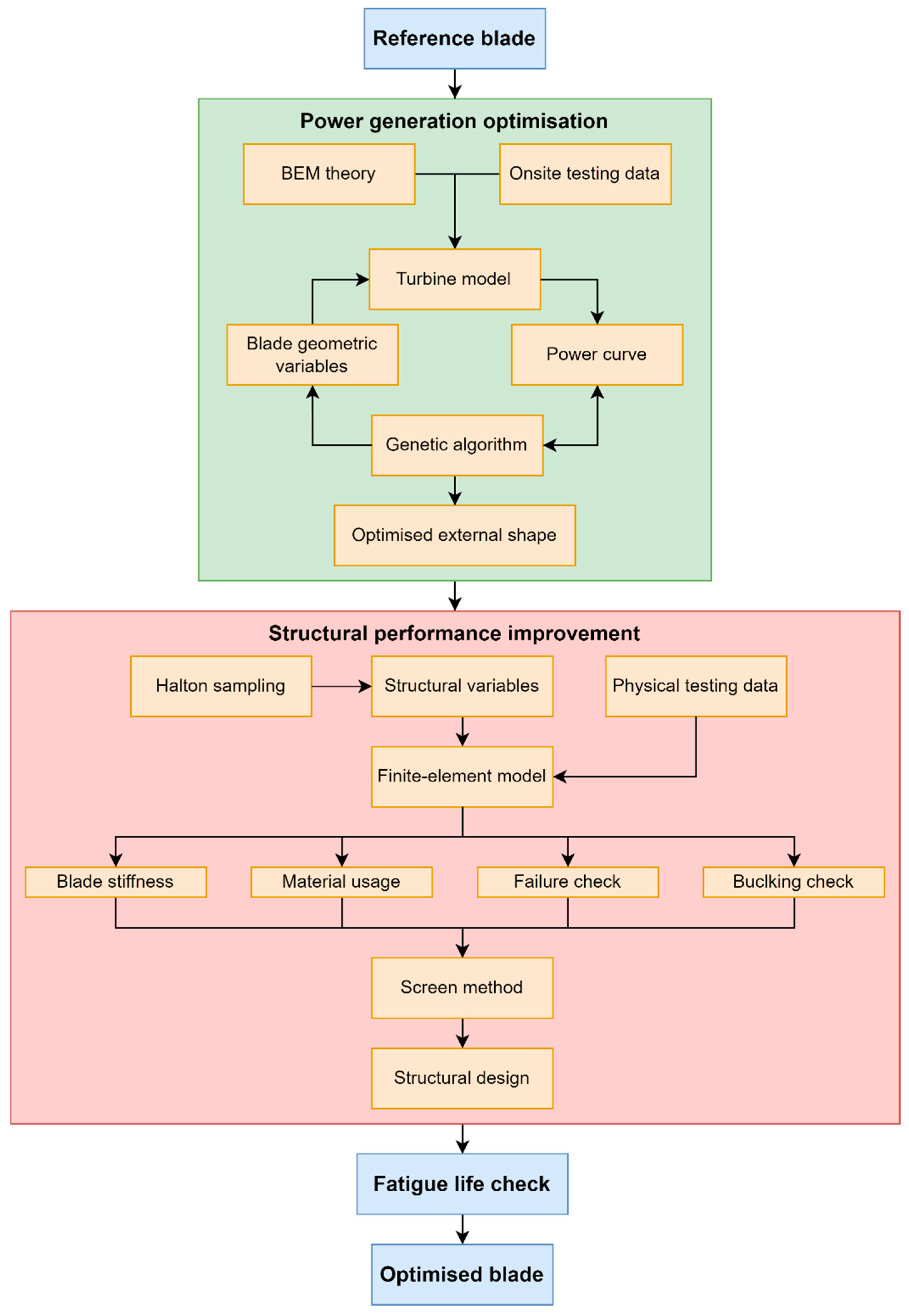
The schematic (Figure 1) summarises the methodology proposed in this study, aiming to upgrade the blades of an existing wind turbine to extend its life. The main objective is to improve the efficiency of the wind turbine blade, in terms of power generation and structural performance. Therefore, the methodology consists of two main steps, namely, power generation optimisation and structural performance enhancement. In the first step, the external geometry of the blade is optimised to increase the power capture efficiency. In the optimisation, a wind turbine model based on BEM theory is employed. To ensure the feasibility of the operation simulation, onsite testing data are utilised to validate the turbine model. The blade external geometry parameters, namely, the airfoil thickness, chord width, and twist angle along the blade, are considered as the input valuables. Since the blade is installed on an existing turbine, the blade length is not considered as an input variable. The genetic algorithm-based method is utilised to optimise the power generation efficiency of the blade. Considering the compatibility between the blade and the hub, the blade root shape is not optimised but the ultimate root forces are controlled so that the hub is not damaged.
With the execution of power generation optimisation, a new blade external geometry is proposed. To ensure the safe operation of the new blade, a blade structural behaviour enhancement study is conducted. The input variables considered in the structural performance improvement are the composite material usage of the blade and the geometry of the spar cap. The screen method is used to generate different sets of input variables. By utilising the physical testing data, an advanced finite element model for composite wind turbine blades is developed and validated. For each variable set, the blade structural performance, in terms of stiffness, failure resistance, buckling factor, and self-weight, is predicted by finite element analyses. On the basis of the outputs of each variable set, a suitable blade structure design can be selected. With the blade external geometry and structure design changed, the blade fatigue life should be verified. Hence, at the end of the methodology, blade fatigue life is analysed through aero-elastic-based turbine simulation. It should be noted that, if the fatigue life of the optimised blade does not meet the minimum requirement, which is typically 20 years, another blade structural design should be selected from the outputs of the structural performance analysis step. This procedure should be repeated until the expected blade fatigue life is achieved. Through the implementation of each step, an optimised blade is proposed for an existing wind turbine.

2.3. Reference Turbine

A 225 kW upwind wind turbine, Vestas V27, was selected as the reference turbine of this study. It is an onshore turbine that was used by wind farms established as early as the 1990s, such as the Ten Mile Lagoon Wind Farm. The turbine is equipped with a 13 m rotor blade (Figure 2), which is manufactured from glass fibre-reinforced powder epoxy composite material. The blade external geometry is constructed using the modified NACA 63 series airfoils, with parameters summarised in Table 1. There are steel inserts in the root of the blade to provide connections to the turbine hub. This blade is the component to be optimised for improving the turbine power generation efficiency and blade structural performance.

2.4. Composite Materials

The reference turbine blade, which is described in Section 2.3, was primarily manufactured from fibre-reinforced powder epoxy composite material [23]. Powder epoxy composite technology has been used as it has several advantages over traditional composite materials, including small through-thickness wet-out requirement, good fibre volume fraction control at the material manufacture stage, and low exotherm during cure, and it requires a vacuum bag only, with an out-of-autoclave cure. The raw material can also be stored at ambient temperatures and has a very long shelf-life when compared to traditional epoxy resins. During this study, the powder epoxy composite technology reinforced with either glass fibre or carbon fibre has been used, which is detailed further, along with the material properties, in Section 4.2.

3. Turbine Efficiency Optimisation

3.1. Turbine Operation Model

Since this step of the methodology focuses on the turbine power generation efficiency under the operation wind speeds, the steady-state performance of the turbine is considered. An accurate turbine model to simulate the operation of the wind turbine should be implemented. Considering that thousands of analyses will be carried out in the genetic algorithm [5]-based optimisation process, the BEM theory [3], the most common method used for simulating turbine operation, is adopted in this study. The wind turbine blade is divided into several 2D blade elements in the BEM theory. By applying the momentum theory to the blade flow path and analysing the lift-drag coefficients of each airfoil along the blade, the performance of the turbine can be evaluated. The outputs of turbine simulation include the lift and drag forces along the blade, the torque induced by the wind forces, and the power generated by the turbine. In the turbine simulation, the tip loss and hub loss are considered using the expressions summarised by Moriarty and Hansen [24]. The turbine simulation based on the BEM theory is less cost-consuming compared to the computational fluid dynamics.
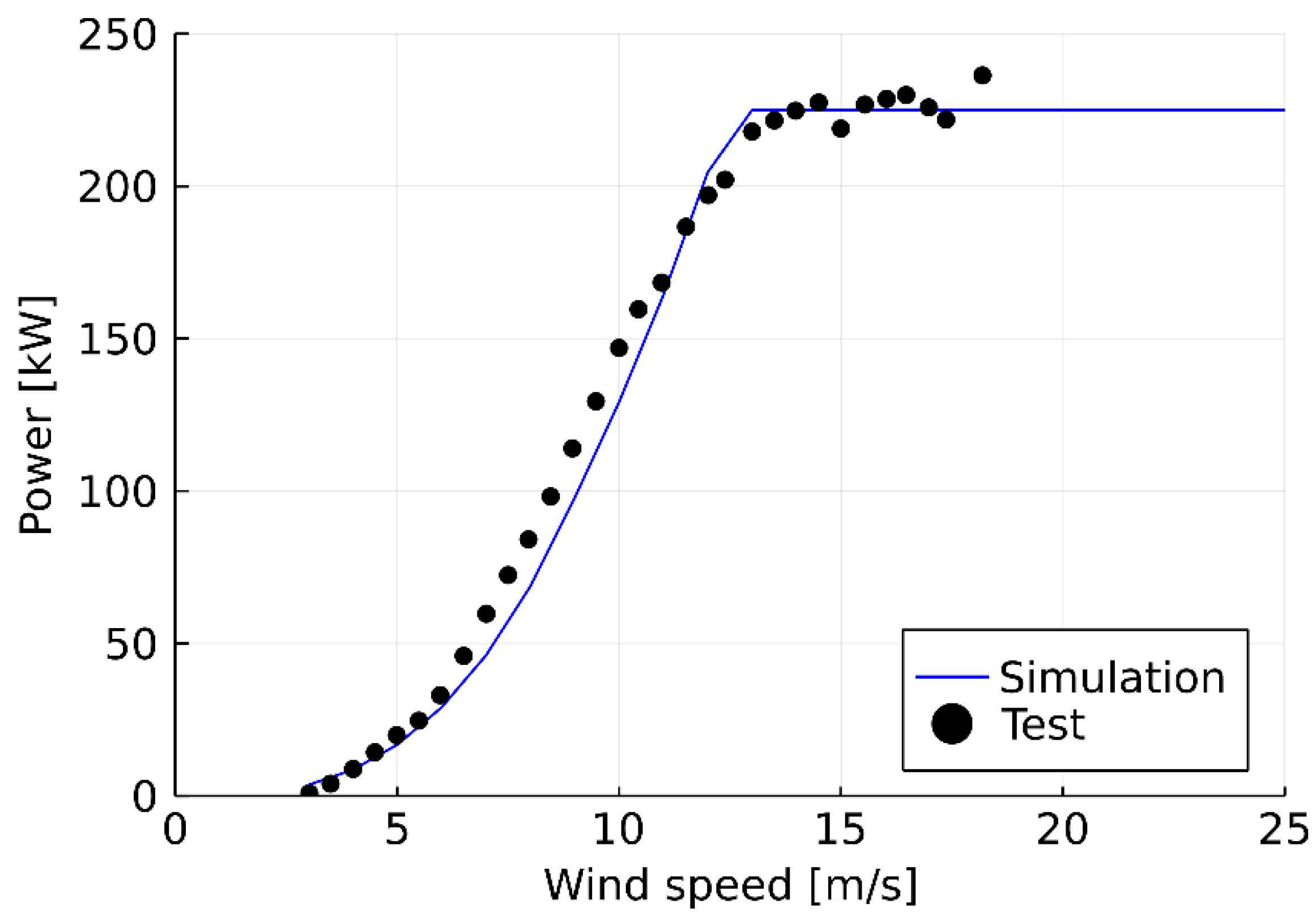
To ensure that the BEM theory-based wind turbine simulation is suitable to provide data for the optimisation study, the performance of the V27 turbine under the operational wind speed range was analysed and validated by the onsite testing data provided by Petersen [25]. Figure 3 compares the power curves predicted by the numerical analysis and the testing data. When the wind speed is in the range of 6 m/s to 12 m/s, the numerical model slightly underestimates the turbine power production, while, for the other wind speeds, the simulation results agree well with the testing data. Overall, the numerical results given by the turbine model can be considered accurate for the wind turbine power prediction.

3.2. Input and Target Variables

The blade external shape is constructed on the basis of the geometric parameters of the 16 cross-sections, as listed in Table 1. The root section (first two cross-sections) of the blade is designed as a cylinder shape to connect to the hub. In the study, the chord width, twist angle, and thickness of each cross-section along the blade are considered as the input variables. Table 2 lists the 42 variables required to build a blade external surface. It should be noted that to be compatible with the existing hub, the cylinder root section is kept the same as that of the reference blade. The chord width and the twist angle of each airfoil are limited up to 2 m and 20°, respectively. The same as the reference blade, the new blade is constructed with modified NACA 63 series airfoils. However, to optimise the turbine efficiency, the thickness of each airfoil is selected as the input variable in the study. The blade cross-section shape is expected to be tapered along its length (except the root region). Therefore, the chord width, twist angle, and thickness of each cross-section are constrained so that the values are less compared to those of the root side adjacent airfoil. The main objective of the blade geometry optimisation is to increase the output power of the turbine under the operation wind speeds (from 3.5 m/s to 25 m/s). For a given set of input variables, the power curve of the turbine can be analysed using the BEM-based turbine model. The area under the power curve, A, is defined as the target variable.
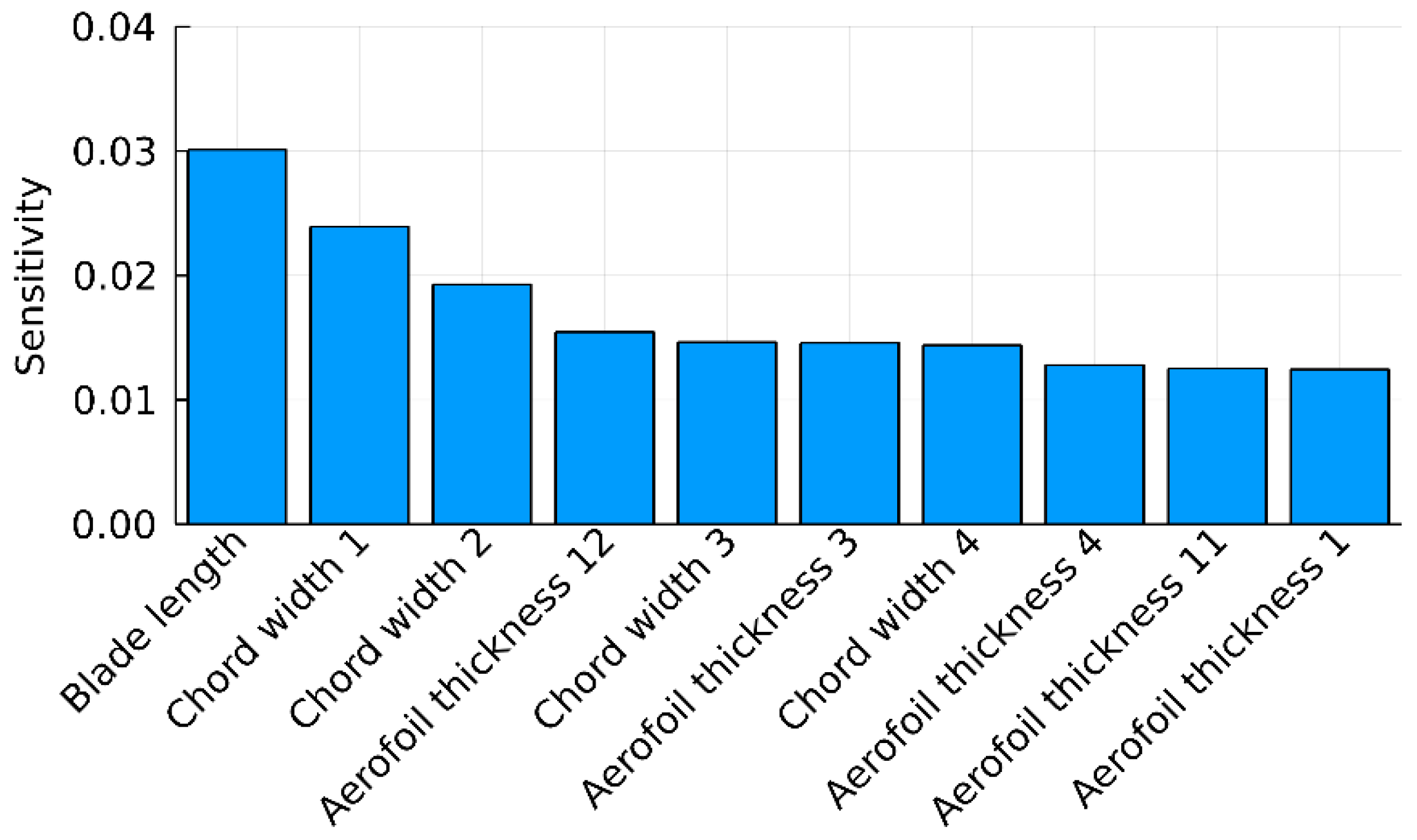
A sensitivity analysis was carried out to determine how the input variables will influence the turbine power generation. The elementary effects method was applied in the sensitivity study. It should be noted that, in addition to the 42 variables listed in Table 2, the blade length was included in the sensitivity analysis. Figure 4 shows the first 10 variables that ranked highest in the analysis. It can be observed that the turbine power production is most sensitive to the blade length. In addition to the blade length, the other nine variables are airfoil thickness and chord width. It can be established that the turbine power production is sensitive to the blade length, airfoil thickness, and chord width, while the twist angle does not play an important role. Although increasing the blade length is the most effective way to increase turbine power production, this variable was not included in the optimisation study. This was limited by the hub height of the turbine. As the main purpose of the study was to extend the operation life of an existing turbine, the hub height was considered unchangeable.

3.3. Optimisation Method

The wind turbine power optimisation was carried out using the genetic algorithm [5], a search heuristic inspired by the process of natural selection. This method is commonly used to generate high-quality solutions to optimisation problems. The main objective of the optimisation is to find a set of input variables that could efficiently improve the power generation of the V27 turbine. Therefore, the target variable, A, which is defined as the area under the power curve of the turbine, was selected to represent the fitness of each input variable set. A higher target variable value means better power production efficiency and vice versa. It should be noted that only the rotor blade was optimised in this study, while the other turbine components (i.e., hub, drive train, tower, etc) remained unchanged. With the increase in turbine power output, more wind energy is captured. This may result in an increase in the blade root force and moment, which can potentially cause damage to the existing hub. Therefore, in addition to improving the power generation, the blade root force and moment should be limited to avoid damaging the other turbine components. However, due to a lack of information about the hub capacities, the maximum blade root shear force and moment were limited to 15.7 kN and 120 kNm, which were obtained from a simulation of the original V27 wind turbine.
At the beginning of the optimisation, several input variable sets, which constitute the constraints listed in Table 2, were generated randomly, with their fitness values analysed. Then, the general genetic algorithm procedures, such as selection, crossover, and elimination, were applied to the variable sets to generate optimised data. At the end of each evolution, the variable set with the highest fitness value was adopted as the optimised solution of the current evolution. This fitness value was compared with that of the previous evolution to calculate the improvement. If the average improvement of the last 50 evolutions was less than 0.01%, the optimisation process was terminated, and the variable set with the highest fitness was selected as the optimised solution.
To explore how the variables can affect the optimisation results, there were four studies carried out in this research. Different input variables (listed in Table 3) were considered in each optimisation while the other parameters, i.e., the objective, constraints, and stop criteria, remain the same.

3.4. Optimisation Results

Four new blades, numbered according to labels in Table 3, were generated after performing the optimisation studies. Figure 5 compares the power curves of the V27 turbine installed with the five rotor blades, including the reference one. The power curve of Blade 1, which only had twist angle optimised, is almost identical to that of the reference blade, indicating that the blade efficiency is not very sensitive to the twist angle. Compared to the twist angle, the power production is more responsive to the chord width as the turbine with Blade 1 produces more power compared to Blade 2. There are a few differences between the power curves of turbines installed with Blade 2 and Blade 3, further proving that the blade efficiency is not sensitive to the twist angle. The turbine with Blade 4 has the highest efficiency out of all, with the rated power reached under a wind speed of 12 m/s instead of 13 m/s. Considering that optimisation 4 includes not only the airfoil chord width and twist angle but also the airfoil thickness, it can be concluded that the blade efficiency is also susceptible to the airfoil thickness. These conclusions are in line with the observations from the sensitivity analysis. Table 4 summarises the relative power production improvements of the turbine with the four blades installed. It can be found that, when the wind speed is less than 10 m/s, the improvements of the four blades are less significant compared to those under higher wind speeds. When the wind speed is larger than 10 m/s, the power generation improvement of using Blade 4 is approximately 10%. This is higher than the 7.96% and 7% power increase obtained by Yang et al. [6] and Li et al. [9], respectively. It can be concluded that, to achieve relatively high efficiency, conditions with wind speeds larger than 10 m/s are preferable. However, considering that the typical hub height of the V27 wind turbine is around 27 m, the probability of wind speed exceeding 10 m/s is low. Hence, a comparison of power curves cannot directly show how much more power can the generated with the new rotor blades.
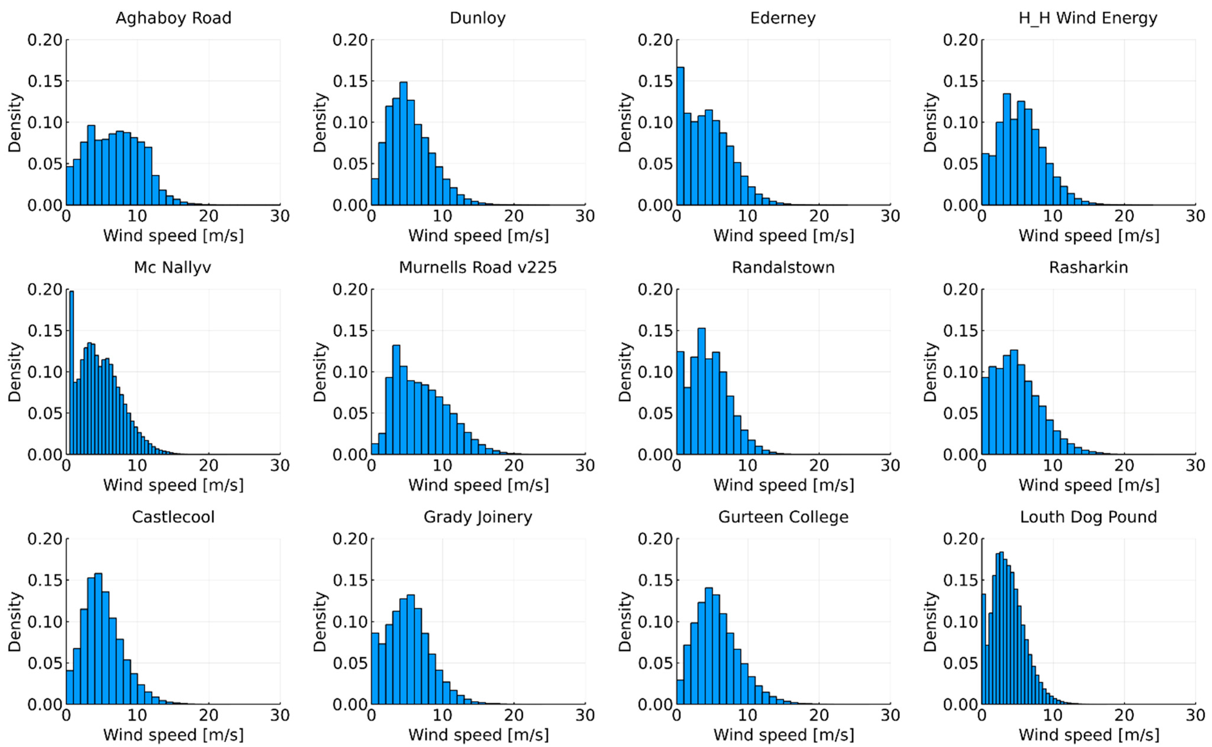
Hence, 12 locations on the Island of Ireland were selected for estimating the annual power production of the turbines. The wind data were obtained from the supervisory control and data acquisition (SCADA) data of wind turbines and the records of met masts [26]. Figure 6 plots the wind speed distribution of the 12 locations. The average wind speeds range from 2 m/s to 7 m/s in these locations. This proves that the probability of having a wind speed larger than 10 m/s is relatively low, indicating that the improvement of the turbine power production may not be as significant as demonstrated by the power curves.
The estimated annual power generations of the turbines at the 12 locations are analysed and listed in Table 5. With different wind speed distributions, the annual power of the reference turbine ranges from 204 MW to 666 MW, showing that the turbine power production is sensitive to the locations. The power generation improvements of the four turbines are also summarised in Table 5. The improvements brought by the new blades are related to the locations. For instance, the annual power production improvement of the turbine with Blade 4 installed ranges from 3.43% to 5.28% compared to that of the reference turbine. The maximum annual power production improvement (5.28%) is at roughly the same level as the 5.87% increase achieved by Shen et al. [8]. The average improvement of Blade 2, 0.61%, is the lowest out of the four. The turbines with Blade 1 and Blade 3 have power generation increases of 2.01% and 2.66%, respectively. Blade 4 brings the turbine an average improvement of 4.22%, where there is a power production improvement of approximately 10.5% at a wind speed of 11 m/s. The comparison of the power generation indicates that the power generation efficiency is more sensitive to the airfoil chord width and thickness compared to the twist angle, the same as the conclusion in the power curve comparisons. It can be observed that the turbines located at Aghaboy Road, which has the highest average wind speed, have the highest benefits from upgrading the blades. Therefore, the improvement in power production is related to the average wind speed, the location with a higher average wind speed will benefit more from replacing the blades. This is in line with the observations from the power curve comparisons. By conducting the optimisation, the power generation of the turbine can have an average increase of 4.22% (Blade 4), which would bring economic benefits to the wind farm.
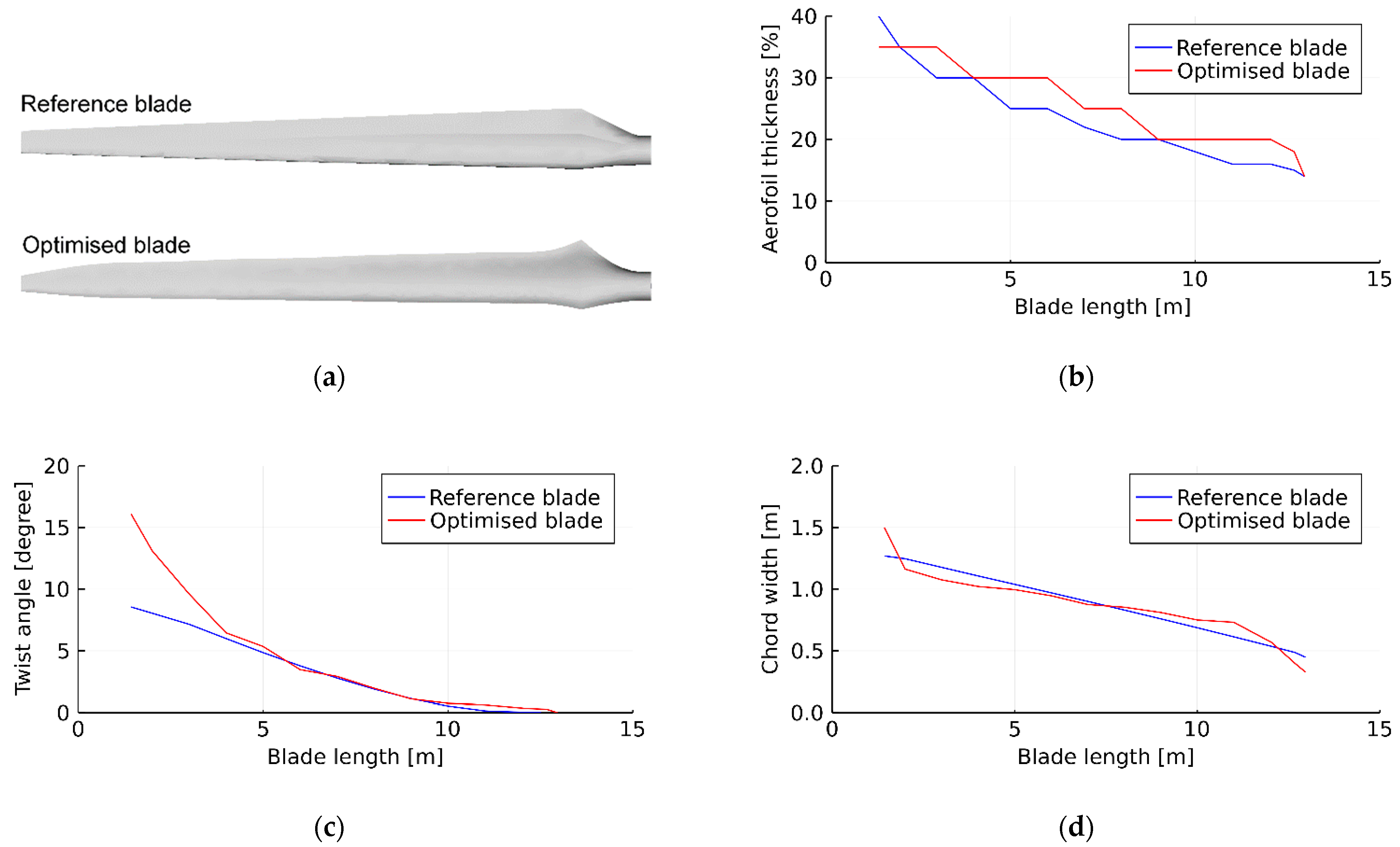
On the basis of the aforementioned comparisons, Blade 4 was selected as the optimised blade for extending the operating life of the V27 wind turbine. It should be highlighted that, although more energy is captured by the new blade, its ultimate root shear force and moment, 13.4 kN and 10.3 kNm, are lower compared to that of the reference blade. This guarantees that the hub will not be damaged with the new blades installed, proving the feasibility of the methodology for wind turbine life extension. Table 6 summarises the geometric parameters of this optimised blade. The external shape and geometric parameters of the optimised blade are compared with the reference blade in Figure 7. As can be seen, most of the airfoil thicknesses are increased to obtain a better balance of drag and lift coefficients. Only the twist angles of the first few airfoils are increased. However, according to the previous discussions, the blade performance does not improve too much by changing the twist angles. At the length range of 7.5 m to 12 m, the airfoil chord widths are raised to generate more torque, while, for the first few airfoils (except the first one), the chord widths are reduced. It can be concluded that the torque is more responsive to the chord width around the tip regions than that of the root region.

4. Structural Performance Enhancement

4.1. Physical Testing and Numerical Model Development

With the blade external geometry optimised, the power production efficiency of the V27 wind turbine is improved. However, the structural performance of the blade is also important to the turbine. The blade should be strong enough to survive under extreme weather. For this purpose, this step focuses on the structural behaviour enhancement of the blade.
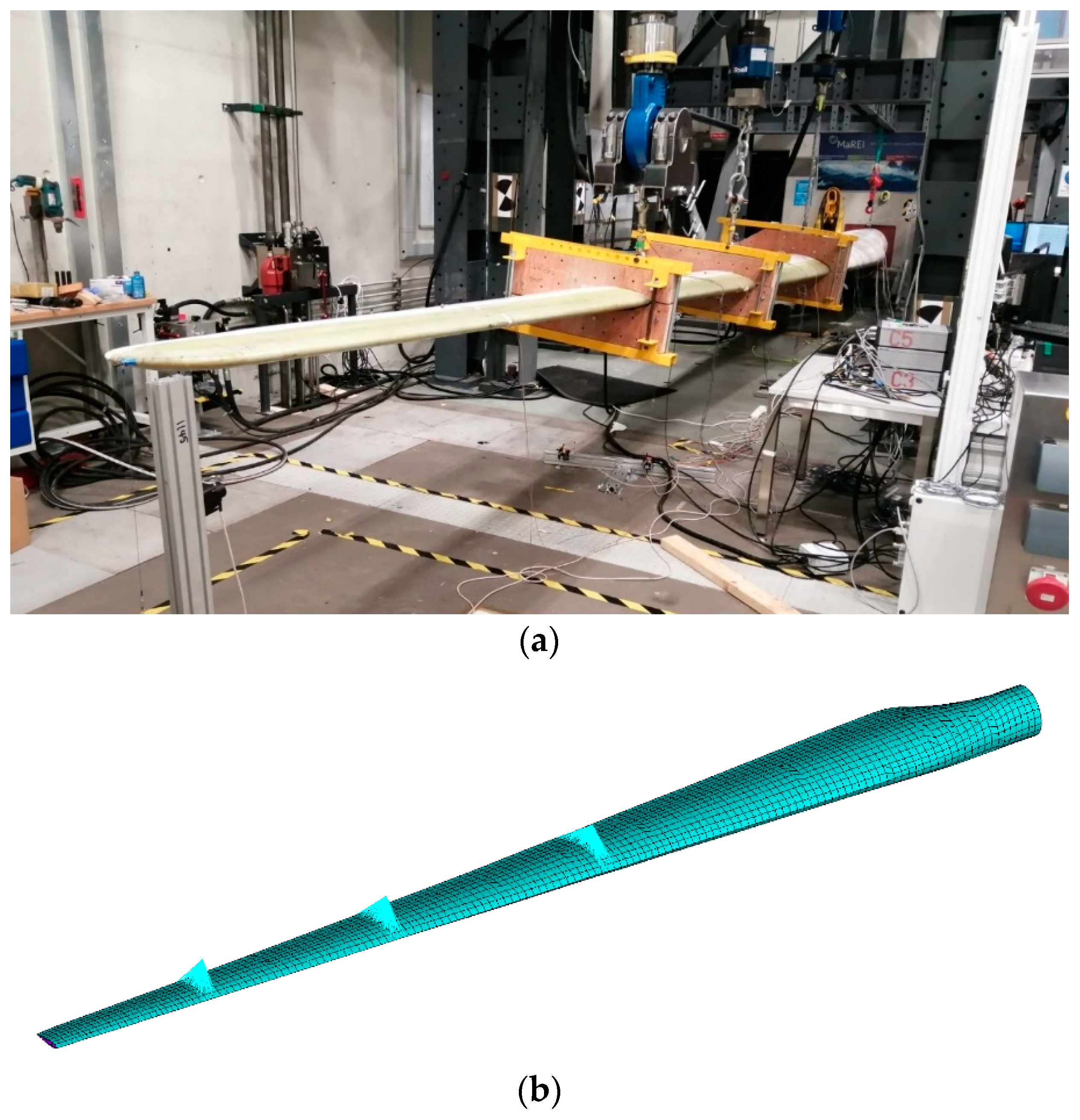
The reference blade is mainly manufactured with glass fibre-reinforced polymer (GFRP) materials. This composite blade weighs 674 kg. In the research studies carried out by Finnegan et al. [27], the reference blade was physically tested in the Large Structures Test Laboratory at the University of Galway (Figure 8a) to ensure its safety under extreme load cases. No failure was observed during testing. In addition to physical testing, the finite element (FE) model, developed in Ansys Mechanical [28] was validated by Finnegan et al. [27] to predict the structural behaviour of the blade. The in-house developed turbine blade design and optimisation software, BladeComp [29], was utilised to generate the FE model. As can be seen in Figure 8b, the FE model of the reference turbine was constructed using the SHELL281 element. The MPC184 element was used to simulate the load induction mechanism of the tests. By comparing the blade deflection (Figure 9a) and strain values (Figure 9b) recorded from the tests and predicted by the FE model, it can be concluded that the FE model is accurate to predict the stiffness and the strain distribution of the blade under wind loads. Further details about the reference blade, the test programme, the test results, and the numerical model can be found in Finnegan et al. [27].

4.2. Blade Materials

With an accurate structural model of the composite blade proposed, a case study was carried out to obtain the structural details for the optimised blade. The objective was to make the new blade stronger compared to the reference blade while the self-weight can be controlled.
Despite the metal inserts embedded at the root, the blade is mainly made from unidirectional (UD) and triaxial (TRI) GFRP composites, with lightweight polyurethane (PU) material inserted to prevent shell local buckling. The detailed mechanical properties of these materials can be found in Finnegan et al. [27].
The UD composite material has good compressive and tensile strength along the fibre direction, which contributes to the flexural stiffness of the blade. Hence, the blade spar cap, the main structural component to resist wind loads, is manufactured with UD materials. In recent years, many researchers [15,16,22] turned to the use of UD CFRP in the wind turbine blade considering the excellent performance of carbon fibre. Table 7 compares the mechanical properties of the UD GFRP and CFRP laminates, where the data of CFRP are from the material database of Ansys [28]. The elastic stiffness and strength of UD CFRP are much higher than those of UD GFRP. Hence, for manufacturing the spar cap of the optimised blade, the UD CFRP was used instead of the UD GFRP.

4.3. Blade Structure and Input Variables

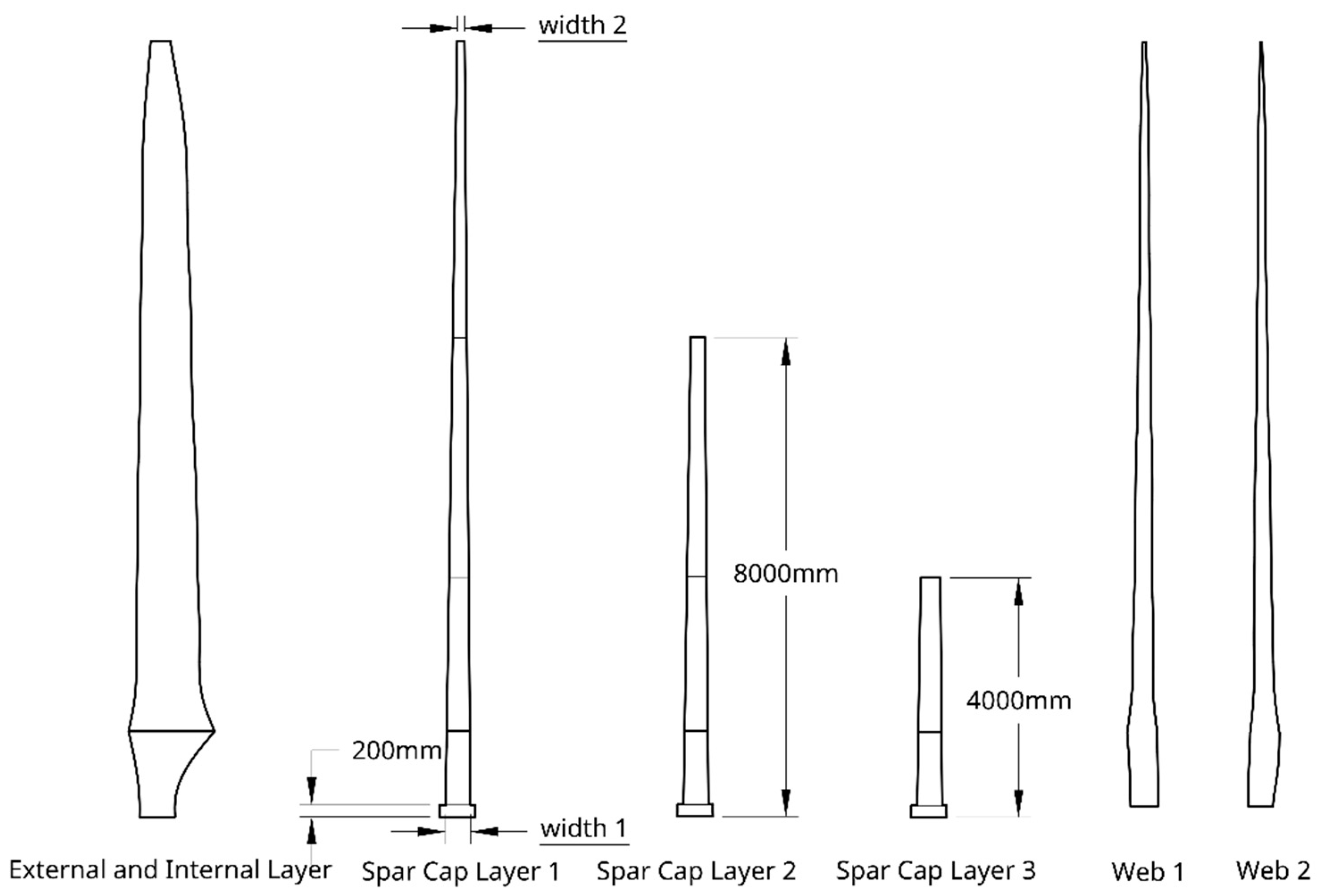
To build the structural model of the optimised blade, the ply number of each composite layer and the geometry of the spar should be known. These numbers are considered as input variables for the structural design, as listed in Table 8. Similar to the reference blade, the optimised blade can be broken down into several layers based on the composite fabric types. Figure 10 shows the composite layers of the optimised blade, which consists of one external layer, three spar cap layers, one internal layer, and two web layers. The spar cap is the key component of the blade to resist flexural loading. Hence, it is expected to be made by UD CFRP. Considering that the blade is a slender structure and suffers higher moments at the root compared to the tip, the spar cap consists of three UD CFRP layers (ply number n2, n3, and n4 in Table 8). This enables the spar cap to have a tapered thickness, making it efficient in moment resisting and material consumption. In addition to the spar cap thickness, the spar cap shape is defined by the tip width and root width, which are included as the input variables of the design (n6 and n7 in Table 8). The external and internal layers, made with TRI GFRP, are designed to have the same ply number (n1 in Table 8). In addition to the composite materials, lightweight PU materials are necessary to increase the shell thickness (n8 in Table 8), aiming at the prevention of local buckling of the blade shell. Inside the blade shell, there are two webs connected to the edges of the spar cap to form a box section, which is efficient for load resisting. Similar to the external layers, the two webs are designed to be TRI GFRP with PU lightweight material, with ply number and PU thickness defined as n5 and n9, respectively.

4.4. Structural Optimisation Objective

With input variables adopted, a case study was performed to figure out a suitable set of variables that make the structural performance of the optimised blade better than that of the reference blade, especially in terms of stiffness and material usage. The methodology of finding the solution is proposed on the basis of the direct screen method, by generating samples that cover the input variable ranges and analysing the blade performance. The candidate design values of each input variable are listed in Table 7. By using the discrete values, the number of generated samples can be reduced, which can speed up the analysis progress. To cover the range of the candidate design values, the input variables are generated as a Halton sequence. In this step, 1000 sets of input variables are created.
For rating the structural performance of the new blade, the multiple target variables, related to the stiffness, strength, and material usage, are defined. For each set of variables, an FE model of the optimised blade is generated. The blade self-weight, which represents the material usage, is one of the target variables. On the basis of the FE model, a static analysis, by applying the testing loads from the physical tests (Finnegan et al. [27]), is performed, and the blade deflection is considered as another target variable, which represents the blade stiffness. According to the stress output from the analysis, failure analysis and buckling analysis are performed to ensure the composite shell does not break or buckle under loading. The Puck failure theory [30] is employed to calculate the maximum inverse reserve factor, which is one of the target variables. From the buckling analysis, the load factor is used as the last target variable. The objective of the structure design is to reduce the blade weight and increase the stiffness, while the failure inverse reserve factor and buckling load factor are limited to avoid blade failure.

4.5. Results and Discussion

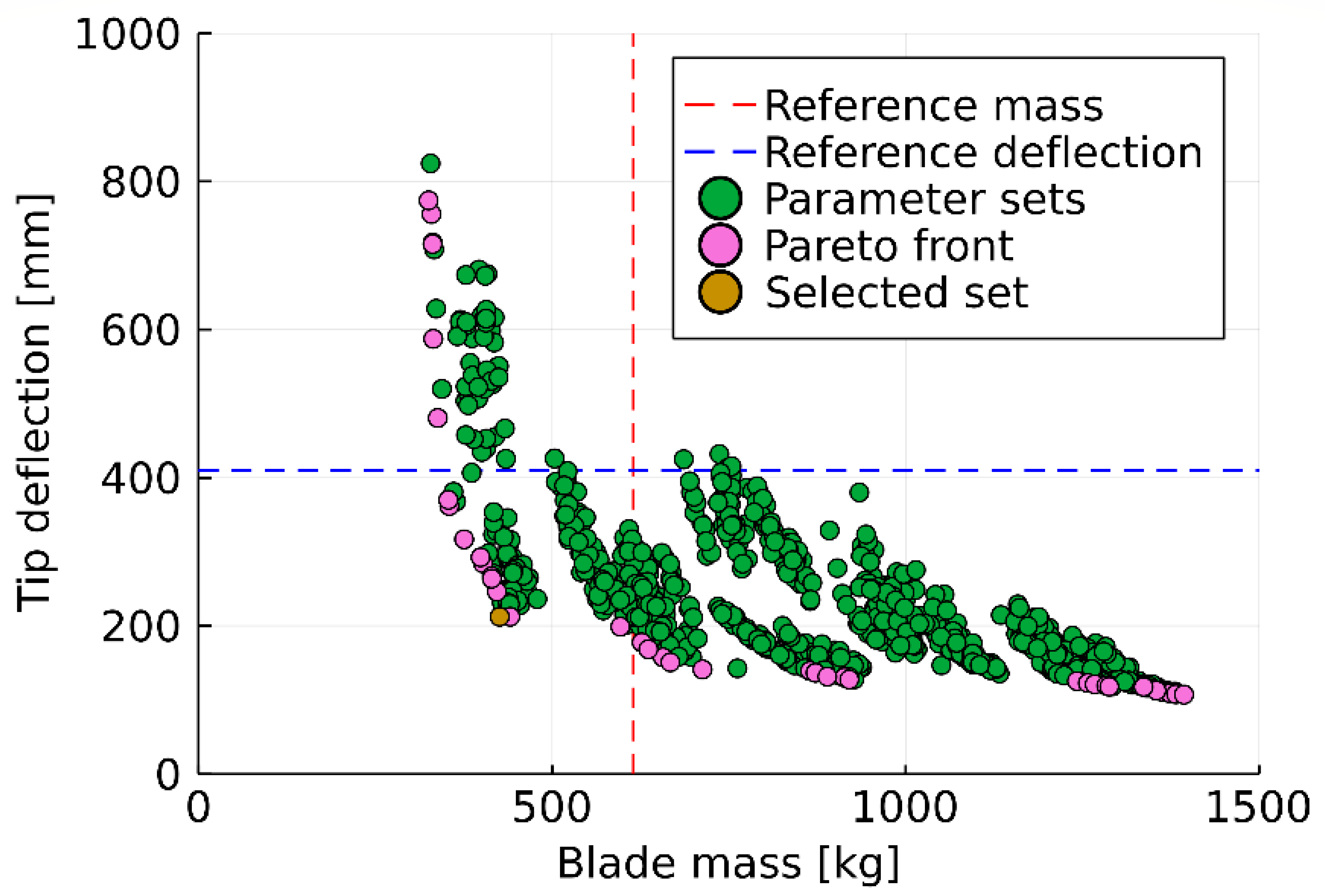
By analysing the blades with the 1000 input variable sets, the structural performances are screened and selected on the basis of the target variables. The maximum failure inverse reserve factor and the buckling load factor are limited to 0.65 and 4 so that a good margin of safety is ensured for the blade. Figure 11 plots the blade tip deflection versus mass results after the variable sets are filtered according to the failure analysis and buckling analysis results. With the increase in blade stiffness, the blade self-weight rises, resulting in more material usage. To find an optimal solution, the Pareto front of the dataset is obtained and marked in Figure 11. The best input set should be selected from the Pareto front since it contains the set with the highest optimisation level. The properties of the reference blade are indicated in the plot, which divides the plot into four areas. The solutions sitting in the lower left zone of the plot exhibit better performance compared to the reference blade due to their lower mass and higher stiffness. This benefits from the usage of UD CFRP composites and a proper structural layout. The optimal input variable set is marked in the plots, with the selected values listed in Figure 11. With this variable set, the blade self-weight has a reduction of 31%, which is higher than the 8.3%, 16%, and 20% improvements obtained by Serafeim et al. [31], Fagan et al. [15], and Sjølund and Lund [22]. In addition to saving on mass, a reduction of 48% in blade tip deflection is achieved with the new structural design. These improvements in blade stiffness and self-weight indicate that an excellent structural improvement of the reference blade is established, proving the feasibility of the optimisation methodology.
Within this methodology, an optimised wind turbine blade with a new aerodynamic and structural design is proposed. Both the power production efficiency of the turbine under operational wind speeds and the safety of the blade under the extreme load case are guaranteed. However, to ensure the operation life of the wind turbine, the blade should have a fatigue life of 20 years. For this purpose, a turbine operation based on OpenFAST [32], a wind turbine situation tool, is carried out. Cork, Ireland, with a wind class of 1.5, is selected as the location of the wind turbine. By simulating the wind turbine under different wind conditions, the loads for the fatigue analysis are obtained. Since the spar cap is the main load-resistance component of the blade, the fatigue failure of the spar cap is considered as the failure occurrence of the blade. The testing results from Gaier et al. [33] are used as the fatigue data of the UD CFRP composites. In the fatigue analysis, the loads are divided into two groups, one in the flapwise direction and one in the edgewise direction. The fatigue lives of the two load groups are analysed separately. Figure 12 shows the rainflow counts of the blade root moments in the two directions. Miner’s rule is used to obtain the cumulative damage. For fatigue analysis of the composite laminates, two loading angles are considered, i.e., 0° and 90° to the fibre direction. The fatigue failure was found to occur at the 90° direction of the UD material, with a life of 23.73 years, which is in excess of the expected operational design life of the blade of 20 years. It can be concluded that, with the proposed blade optimisation methodology applied for an existing wind turbine, the optimised solution provides the new blade with a higher power generation efficiency, better stiffness, and sufficient fatigue life.

5. Conclusions

In this research, a rotor blade upgrade methodology was proposed to extend the operation life of existing turbines. This methodology focuses on optimising the power generation efficiency and structural performance of a wind turbine blade. One of the advantages of utilising this methodology is that not only was the blade external geometry optimised but the geometries and structural details of each blade interior components were also proposed. The optimisation outputs directly provide the blade design with details up to the composite ply level. This enables the manufacturer to build the new blade with just a few additional specifics. Benefiting from the shell-based full-scale blade FE model employed by the methodology, the blade failure risk under multi-axis stress status, calculated on the basis of the advanced composite failure theory, could be included as the optimisation objective. The capacity of rotor connections was included as one of the design constraints, ensuring that the optimised blade was suitable for the existing wind turbine. Moreover, the wind turbine simulation tool and FE model utilised in the optimisation methodology were both validated against physical testing data, which guaranteed the accuracy of the output results.
By applying the methodology, a high-efficiency rotor blade was proposed for extending the operating life of an existing wind turbine, Vestas V27. The accuracy of the numerical models employed to optimise the blade was validated by testing data. By comparing the performance between the optimised blade and the reference blade, it was found to be promising to improve the blade efficiency without changing the blade length. Moreover, with the increase in power production, the shear force and moment can be maintained at the same level as the reference blade by using this methodology. Hence, no additional force was introduced to the hub with the new blades. This ensures compatibility between the optimised blade and the existing turbine hub. By analysing the annual power production of the turbine at 12 different locations, the optimised blade was shown to bring an average improvement of 4.22%, with a power production improvement of approximately 10.5% at a wind speed of 11 m/s. The benefit brought by the optimised blade depends on the wind distribution of the turbine location. A place with a higher average wind speed can have a better power production improvement. The blade structural behaviour, in terms of stiffness, self-weight, failure, and buckling resistance, was improved by using the high-strength carbon fibre composite material and optimising the blade structure. The blade self-weight and tip deflection were proven to reduce by 31% and 48%, respectively. The fatigue life of the proposed new blade was verified to be more than 20 years by simulating the turbine operation under different wind conditions using the aero-elastic analysis. The proposed optimisation methodology was verified to be efficient in generating highly efficient rotor blades for existing wind turbines, in terms of power production and structure performance.
However, there are a number of limitations in applying the proposed methodology. As described in Section 2.2, there are three steps involved in the methodology, namely, the power production optimisation, structural performance optimisation, and fatigue life check. In the first step, the blade is assumed to be rigid as the structural design is unknown at this stage. Hence, the influence of the blade mechanical properties on wind turbine power production is not considered. Moreover, the blade fatigue life is not considered as an objective during the structural performance. This is due to the complexity of the fatigue analysis since it requires both aerodynamic and structural analyses. Therefore, the aero-elastic-based analysis is conducted in the last step to ensure the fatigue life satisfies the requirement. If the blade fatigue life does not meet the expectation, another blade design should be selected from step 2 and the fatigue analysis should be repeated. This may introduce additional work to the optimisation. Therefore, as part of a future study, a fully coupled aero-elastic analysis will be introduced to the optimisation methodology so that only a single step is required for optimising the rotor blade for life extension of existing wind turbines. This comprehensive, but reliable, optimisation methodology can include the blade fatigue life as a design objective and make it controllable.
Author Contributions

Conceptualisation, Y.J.; methodology, Y.J.; validation, Y.J. and W.F; formal analysis, Y.J. and W.F; investigation, Y.J., W.F. and T.F.; data curation, Y.J. and W.F.; writing—original draft preparation, Y.J. and W.F; writing—review and editing, Y.J., W.F., T.F. and J.G.; supervision, T.F. and J.G.; project administration, T.F. and J.G.; funding acquisition, W.F., T.F. and J.G. All authors have read and agreed to the published version of the manuscript.

Funding

This work was funded by the Sustainable Energy Authority of Ireland (SEAI) under the SEAI Research, Development, and Demonstration Funding Programme 2021, grant number 21/RDD/630 and grant number 21/RDD/601. The research was also supported by Science Foundation Ireland (SFI) through the MaREI Research Centre for Energy, Climate, and Marine (grant no. 12/RC/2302_2). The authors would also like to acknowledge the support of SFI through the SFI Industry Fellowship Programme (grant no. 19/IFA/7417) and the Marine Institute, funded under the Marine Research Programme by the Government of Ireland (PDOC/21/03/01).

Data Availability Statement

Testing data used in this research can be found in https://www.seanoe.org/data/00694/80564/, accessed on 13 December 2022.

Acknowledgments

The authors would like to acknowledge the support from the technical staff at Large Structures Testing Laboratory, School of Engineering, University of Galway.

Conflicts of Interest

The authors declare no conflict of interest.

References

  1. Why the EU Supports Wind Energy Research and Innovation. Available online: https://ec.europa.eu/info/research-and-innovation/research-area/energy-research-and-innovation/wind-energy_en (accessed on 16 January 2022).
  2. SEAI Energy in Ireland 2020 Report; Sustainable Energy Authority of Ireland (SEAI): Dublin, Ireland, 2020.
  3. Branlard, E. The Blade Element Momentum (BEM) Method. In Research Topics in Wind Energy; 2017; pp. 181–211. ISBN 978-3-319-55163-0. [Google Scholar]
  4. Pourrajabian, A.; Nazmi Afshar, P.A.; Ahmadizadeh, M.; Wood, D. Aero-Structural Design and Optimization of a Small Wind Turbine Blade. Renew. Energy 2016, 87, 837–848. [Google Scholar] [CrossRef]
  5. Mitchell, M. An Introduction to Genetic Algorithms; MIT Press: Cambridge, MA, USA, 1998. [Google Scholar]
  6. Yang, H.; Chen, J.; Pang, X.; Chen, G. A New Aero-Structural Optimization Method for Wind Turbine Blades Used in Low Wind Speed Areas. Compos. Struct. 2019, 207, 446–459. [Google Scholar] [CrossRef]
  7. Chen, Z.; He, Y.; Zhao, Y.; Meng, L.; He, C.; Yang, H.; Han, Z.; Liu, Y. High-Order Redesign Method for Wind Turbine Blade Optimization in Model Test Considering Aerodynamic Similarity. Ocean. Eng. 2020, 202, 107156. [Google Scholar] [CrossRef]
  8. Shen, X.; Chen, J.-G.; Zhu, X.-C.; Liu, P.-Y.; Du, Z.-H. Multi-Objective Optimization of Wind Turbine Blades Using Lifting Surface Method. Energy 2015, 90, 1111–1121. [Google Scholar] [CrossRef] [Green Version]
  9. Li, Y.; Wei, K.; Yang, W.; Wang, Q. Improving Wind Turbine Blade Based on Multi-Objective Particle Swarm Optimization. Renew. Energy 2020, 161, 525–542. [Google Scholar] [CrossRef]
  10. Wang, Q.; Luo, K.; Yuan, R.; Wang, S.; Fan, J.; Cen, K. A Multiscale Numerical Framework Coupled with Control Strategies for Simulating a Wind Farm in Complex Terrain. Energy 2020, 203, 117913. [Google Scholar] [CrossRef]
  11. Wang, Q.; Luo, K.; Wu, C.; Mu, Y.; Tan, J.; Fan, J. Diurnal Impact of Atmospheric Stability on Inter-Farm Wake and Power Generation Efficiency at Neighboring Onshore Wind Farms in Complex Terrain. Energy Convers. Manag. 2022, 267, 115897. [Google Scholar] [CrossRef]
  12. Naresh, K.; Shankar, K.; Rao, B.S.; Velmurugan, R. Effect of High Strain Rate on Glass/Carbon/Hybrid Fiber Reinforced Epoxy Laminated Composites. Compos. Part B Eng. 2016, 100, 125–135. [Google Scholar] [CrossRef]
  13. Aklilu, G.; Adali, S.; Bright, G. Tensile Behaviour of Hybrid and Non-Hybrid Polymer Composite Specimens at Elevated Temperatures. Eng. Sci. Technol. Int. J. 2019, 23, 732–743. [Google Scholar] [CrossRef]
  14. Chen, D.; Sun, G.; Meng, M.; Jin, X.; Li, Q. Flexural Performance and Cost Efficiency of Carbon/Basalt/Glass Hybrid FRP Composite Laminates. Thin-Walled Struct. 2019, 142, 516–531. [Google Scholar] [CrossRef]
  15. Fagan, E.M.; De La Torre, O.; Leen, S.B.; Goggins, J. Validation of the Multi-Objective Structural Optimisation of a Composite Wind Turbine Blade. Compos. Struct. 2018, 204, 567–577. [Google Scholar] [CrossRef]
  16. Gaertner, E.; Rinker, J.; Sethuraman, L.; Zahle, F.; Anderson, B.; Barter, G.; Abbas, N.; Meng, F.; Bortolotti, P.; Skrzypinski, W.; et al. Definition of the IEA 15 MW Offshore Reference Wind Turbine; International Energy Agency: Paris, France, 2020. [Google Scholar]
  17. Singh, H.K.; Isaacs, A.; Ray, T.; Smith, W. Infeasibility Driven Evolutionary Algorithm (IDEA) for Engineering Design Optimization. In Proceedings of the AI 2008: Advances in Artificial Intelligence, Auckland, New Zealand, 3–5 December 2008; Wobcke, W., Zhang, M., Eds.; Springer: Berlin/Heidelberg, Germany, 2008; pp. 104–115. [Google Scholar]
  18. Barnes, R.H.; Morozov, E.V. Structural Optimisation of Composite Wind Turbine Blade Structures with Variations of Internal Geometry Configuration. Compos. Struct. 2016, 152, 158–167. [Google Scholar] [CrossRef]
  19. Fagan, E.M.; Flanagan, M.; Leen, S.B.; Flanagan, T.; Doyle, A.; Goggins, J. Physical Experimental Static Testing and Structural Design Optimisation for a Composite Wind Turbine Blade. Compos. Struct. 2017, 164, 90–103. [Google Scholar] [CrossRef] [Green Version]
  20. Jiang, Y.; Finnegan, W.; Allen, R.; Coyne, C.; Flanagan, M.; Flanagan, T.; Goggins, J. Surface Manufacturing Quality Assessment of a 1-MW Tidal Turbine Blade Using 3D Laser Scanning Technique. In Proceedings of the The proceedings of the 14th European Wave and Tidal Energy Conference, Plymouth, UK, 5–9 September 2021. [Google Scholar]
  21. Fagan, E.M.; Wallace, F.; Jiang, Y.; Kazemi, A.; Goggins, J. Design and Testing of a Full-Scale 2 MW Tidal Turbine Blade. In Proceedings of the Thirteenth European Wave and Tidal Energy Conference, Naples, Italy, 1–6 September 2019; Vicinanza, D., Ed.; EWTEC: Universitá Degli Studi della Campania “Luigi Vanvitelli”: Naples, Italy, 2019. [Google Scholar]
  22. Sjølund, J.H.; Lund, E. Structural Gradient Based Sizing Optimization of Wind Turbine Blades with Fixed Outer Geometry. Compos. Struct. 2018, 203, 725–739. [Google Scholar] [CrossRef] [Green Version]
  23. Finnegan, W.; Allen, R.; Glennon, C.; Maguire, J.; Flanagan, M.; Flanagan, T. Manufacture of High-Performance Tidal Turbine Blades Using Advanced Composite Manufacturing Technologies. Appl. Compos. Mater. 2021, 28, 2061–2086. [Google Scholar] [CrossRef]
  24. Moriarty, P.J.; Hansen, A.C. AeroDyn Theory Manual; National Renewable Energy Lab.: Golden, CO, USA, 2005. [Google Scholar]
  25. Petersen, S.M. Wind Turbine Test VESTAS V27-225 KW; RISø National Laboratory: Roskilde, Denmark, 1990. [Google Scholar]
  26. BrightHub. Available online: https://brighthub.io/map-view (accessed on 5 January 2022).
  27. Finnegan, W.; Jiang, Y.; Dumergue, N.; Davies, P.; Goggins, J. Investigation and Validation of Numerical Models for Composite Wind Turbine Blades. J. Mar. Sci. Eng. 2021, 9, 525. [Google Scholar] [CrossRef]
  28. Ansys®. Academic Research Mechanical, Release 17.1; Help System, Mechanical APDL; ANSYS, Inc.: Canonsburg, PA, USA, 2016. [Google Scholar]
  29. BladeComp—NUI Galway. Available online: https://www.nuigalway.ie/structures/bladecomp/# (accessed on 27 September 2021).
  30. Puck, A.; Schürmann, H. Failure Analysis of FRP Laminates by Means of Physically Based Phenomenological Models. Compos. Sci. Technol. 1998, 58, 1045–1067. [Google Scholar] [CrossRef]
  31. Serafeim, G.P.; Manolas, D.I.; Riziotis, V.A.; Chaviaropoulos, P.K.; Saravanos, D.A. Optimized Blade Mass Reduction of a 10MW-Scale Wind Turbine via Combined Application of Passive Control Techniques Based on Flap-Edge and Bend-Twist Coupling Effects. J. Wind. Eng. Ind. Aerodyn. 2022, 225, 105002. [Google Scholar] [CrossRef]
  32. OpenFAST. Available online: https://www.nrel.gov/wind/nwtc/openfast.html (accessed on 7 January 2022).
  33. Gaier, C.; Fischmeister, S.; Maier, J.; Pinter, G. Fatigue Analysis of Continuously Carbon Fiber Reinforced Laminates. SAE Int. J. Engines 2017, 10, 305–315. [Google Scholar] [CrossRef]
Figure 1. Methodology for improving blade efficiency for an existing wind turbine.
Energies 16 00102 g001
Figure 2. The 13 m wind turbine blades.
Energies 16 00102 g002
Figure 3. Power curve comparison between the simulated data and the testing results.
Energies 16 00102 g003
Figure 4. Sensitivity analysis results of the reference wind turbine blade geometric variables.
Energies 16 00102 g004
Figure 5. Power curve comparisons of the V27 wind turbine with the optimised blades.
Energies 16 00102 g005
Figure 6. Wind speed distributions of the 12 selected locations.
Energies 16 00102 g006
Figure 7. Geometry comparison between the reference blade and the optimised blade in terms of (a) blade shape, (b) airfoil thickness, (c) twist angle, and (d) chord width.
Energies 16 00102 g007
Figure 8. (a) Test setup of the reference wind turbine blade; (b) FE model of the reference wind turbine blade.
Energies 16 00102 g008
Figure 9. Validation of the FE model: (a) comparison of the blade deflection; (b) comparison of the spar cap strain distribution (under flapwise static loading, 100% load case).
Energies 16 00102 g009
Figure 10. Composite layers of the new wind turbine blade.
Energies 16 00102 g010
Figure 11. Results of the generated blades.
Energies 16 00102 g011
Figure 12. Rainflow counting of the blade root moments.
Energies 16 00102 g012
Table 1. Geometric section parameters of the reference 13 m wind turbine blade.
Profile #LocationAirfoil ThicknessChord Length [m]Twist Angle [°]
1 *0100%0.69.3
2 *0.02100%0.69.3
30.1140%1.278.6
40.1535%1.258.1
50.2330%1.187.2
60.3130%1.116
70.3925%1.044.9
80.4625%0.973.8
90.5422%0.92.8
100.6220%0.831.9
110.6920%0.761.1
120.7718%0.690.5
130.8516%0.610.1
140.9316%0.540
150.9815%0.490
16114%0.450
* Circular cross-section.
Table 2. Input variables considered in the turbine power production optimisation.
VariableDescriptionRangeConstraintUnit
x1–x14Chord width of each airfoil0–2xi < xi+1 (1 ≤ i ≤ 14)m
x15–x28Twist angle of each airfoil0–20xi < xi+1 (15 ≤ i ≤ 28)°
x29–x42Thickness of each airfoil14–40%xi ≤ xi+1 (29 ≤ i ≤ 42)-
Table 3. Variables considered in the four optimisation studies.
OptimisationChord WidthTwist AngleAirfoil Thickness
Blade 1
Blade 2
Blade 3
Blade 4
○ means that the related variables are included in the blade optimisation.
Table 4. Power production improvements before reaching the rated wind speed.
Windspeed [m/s]Blade 1Blade 2Blade 3Blade 4
30.88%0.37%1.73%2.96%
41.31%0.61%1.66%2.87%
50.92%0.47%1.34%2.55%
61.01%0.31%1.34%2.56%
71.03%0.27%1.38%2.62%
81.13%0.43%1.48%2.69%
91.25%0.57%1.51%2.73%
104.28%1.38%5.40%6.69%
115.50%1.19%7.09%10.49%
123.73%0.98%5.63%9.97%
Table 5. Annual power production estimations of the V27 wind turbine with the optimised blades at different locations in Ireland.
LocationAnnual Power Production [kW]Improvement
Ref. BladeBlade 1Blade 2Blade 3Blade 4Blade 1Blade 2Blade 3Blade 4
Aghaboy Road665,989682,987670,749688,652701,1502.55%0.71%3.40%5.28%
Dunloy397,756405,953400,237408,585414,8302.06%0.62%2.72%4.29%
Ederney372,021379,425374,301381,777387,4921.99%0.61%2.62%4.16%
H&H Wind Energy423,182432,024425,839434,858441,5822.09%0.63%2.76%4.35%
Mc Nallyv362,815370,145365,061372,482378,1692.02%0.62%2.66%4.23%
Murnells Road629,133642,180632,851646,537656,2802.07%0.59%2.77%4.31%
Randalstown311,679317,571313,530319,441324,1391.89%0.59%2.49%4.00%
Rasharkin417,468425,775419,976428,452434,8021.99%0.60%2.63%4.15%
Gurteen College423,012431,501425,571434,233440,7122.01%0.61%2.65%4.18%
Castlecool337,716344,354339,765346,483351,6881.97%0.61%2.60%4.14%
Louth Dog Pound204,345207,516205,422208,542211,3541.55%0.53%2.05%3.43%
Average411,152419,650413,696422,406428,9162.01%0.61%2.66%4.22%
Table 6. Geometric section parameters of the optimised 13 m wind turbine blade.
Profile #LocationAirfoil ThicknessChord Length [m]Twist Angle [°]
1 *0100%0.69.3
2 *0.02100%0.69.3
30.1135%1.516.1
40.1535%1.1613.1
50.2335%1.089.6
60.3130%1.026.5
70.3930%15.4
80.4630%0.953.5
90.5425%0.882.9
100.6225%0.852
110.6920%0.811.1
120.7720%0.750.8
130.8520%0.730.6
140.9320%0.570.4
150.9818%0.40.3
16114%0.330
* Circular cross-section.
Table 7. Mechanical properties of the glass UD and carbon UD materials used in the study.
DescriptionUD GlassUD CarbonUnit
Density19101490kg/m3
0° tensile strength7822231MPa
0° tensile modulus39.7121GPa
90° tensile strength46.529MPa
90° tensile modulus1198.6GPa
0° compression strength6431082MPa
90° compression strength185100MPa
Inter-laminar shear strength73.932MPa
In-plane shear strength53.760MPa
In-plane shear modulus3.674.7GPa
Table 8. Variables considered in the blade structural design.
VariableDescriptionCandidate ValuesResultUnit
n1Ply number of the external and internal layer (TRI)2, 4, 6, 8, 102-
n2Ply number of the spar cap layer 1 (UD)2, 4, 6, 8, 1010-
n3Ply number of the spar cap layer 2 (UD)2, 4, 6, 8, 102-
n4Ply number of the spar cap layer 3 (UD)2, 4, 6, 8, 106-
n5Ply number of the web layer (TRI)2, 4, 6, 8, 104-
n6Tip width of the spar cap50, 70, 90, 110, 130, 150150mm
n7Root width of the spar cap50, 100, 150, 200, 250, 300, 350, 400, 450300mm
n8Thickness of the shell lightweight PU5, 10, 155mm
n9Thickness of the web lightweight PU5, 10, 155mm
Disclaimer/Publisher’s Note: The statements, opinions and data contained in all publications are solely those of the individual author(s) and contributor(s) and not of MDPI and/or the editor(s). MDPI and/or the editor(s) disclaim responsibility for any injury to people or property resulting from any ideas, methods, instructions or products referred to in the content.