Article

Structural and Electrochemical Properties of Layered P2-Na0.8Co0.8Ti0.2O2 Cathode in Sodium-Ion Batteries

1
Leibniz Institute for Solid State and Materials Research (IFW) Dresden e.V., Helmholtzstr. 20, D-01069 Dresden, Germany
2
Institute of Materials Science, Technische Universität Dresden, Helmholtzst. 7, D-01062 Dresden, Germany
*
Author to whom correspondence should be addressed.
Energies 2022, 15(9), 3371; https://doi.org/10.3390/en15093371
Submission received: 29 March 2022 / Revised: 27 April 2022 / Accepted: 28 April 2022 / Published: 5 May 2022

Abstract

:
Layered Na0.8Co0.8Ti0.2O2 oxide crystallizes in the β-RbScO2 structure type (P2 modification) with Co(III) and Ti(IV) cations sharing the same crystallographic site in the metal-oxygen layers. It was synthesized as a single-phase material and characterized as a cathode in Na- and Na-ion batteries. A reversible capacity of about 110 mA h g−1 was obtained during cycling between 4.2 and 1.8 V vs. Na+/Na with a 0.1 C current density. This potential window corresponds to minor structural changes during (de)sodiation, evaluated from operando XRD analysis. This finding is in contrast to Ti-free NaxCoO2 materials showing a multi-step reaction mechanism, thus identifying Ti as a structure stabilizer, similar to other layered O3- and P2-NaxCo1−yTiyO2 oxides. However, charging the battery with the Na0.8Co0.8Ti0.2O2 cathode above 4.2 V results in the reversible formation of a O2-phase, while discharging below 1.5 V leads to the appearance of a second P2-layered phase with a larger unit cell, which disappears completely during subsequent battery charge. Extension of the potential window to higher or lower potentials beyond the 4.2–1.8 V range leads to a faster deterioration of the electrochemical performance. After 100 charging-discharging cycles between 4.2 and 1.8 V, the battery showed a capacity loss of about 20% in a conventional carbonate-based electrolyte. In order to improve the cycling stability, different approaches including protective coatings or layers of the cathodic and anodic surface were applied and compared with each other.

1. Introduction

Increased attention to sodium-containing materials during the last several years is caused by the rapid development of sodium-ion batteries (NIBs), which are now considered as a potential successor for lithium-ion batteries (LIBs) and lead-acid batteries [1,2,3] on the sector of stationary energy storage, although first Na-batteries were investigated already 50 years ago [4]. Layered sodium oxides have gained immense interest due to their potential applicability as electrode materials (both cathode and anode) in NIBs [5,6]. Despite the close chemistries of layered Li- and Na-oxides, the knowledge collected for Li-materials cannot be unrestrictedly transferred to the Na-systems. For example, stable and well performing layered Li-materials with the composition LiNi0.33Mn0.33Co0.33O2 (NMC 111) do not show best capacities as counterparts in Na-cells, if Li was replaced by Na in the material.
A detailed comparison of LiCoO2 and NaCoO2 reveals even more differences. Thus, the temperature-dependent phase diagram of the Na-Co-O system [7] is much more complex than that of Li-Co-O [8], having numerous structural variations in dependence on the temperature and the alkali metal content. Upon chemical or electrochemical removal of the alkali cations, NaxCoO2 undergoes much more intermediate phase transformations with and without cation ordering [9], in comparison to LiCoO2 [10]. Generally, there are four main structural types of layered oxides with Na, usually labelled as P2, O2, O3 and P3. The main difference between them represents various arrangement of closed oxygen packing in the three-dimensional network, resulting in two or three metal-oxygen layers in the unit cell, and different oxygen surrounding for Na cations (octahedral or trigonal prismatic). It was generally assumed that structures with NaO6-octahedra (O3-form) provide a higher specific capacity [11], while structures with NaO6 trigonal prisms (P2-form) facilitate a faster cation diffusion [12]. The main obstacle of the layered materials represents the host rearrangement, which includes phase transition between different stacking sequences, bringing negative impacts on the electrochemical properties in several aspects as energy efficiency, rate capability, and cyclability [6]. All of that is crucial for meeting the demand of large-scale stationary energy storage. Therefore, more efforts are required to maintain a stable P-type intercalation host over a wide range of sodium concentrations.
It is known that a partial replacement of Co by Ti in a Na(Co,Ti)O2 cathode can stabilize the crystal structure during de-sodiation, thus reducing the number of phase transformations [13,14,15,16]. Substitution by Ti leads to the formation either of single phases with different structure types P2, P3 or O3 [13,14,15,16,17], or a mixture of these phases [18] depending on synthesis conditions and the stoichiometry. Sabi et al. have demonstrated that already a small degree of Co-substitution of 5% by Ti in P2-NaxCoO2 reduces the number of phase transformations upon de-sodiation [13], but still multi-phase transitions with co-existence of two phases take place. At a higher Ti-substitution degree of ×(Ti) = 0.5 in NaxCo1−xTixO2, P2-, P3- or O3-phases can be formed in dependence on synthesis conditions as pre-treatment of the precursor, synthesis temperature and the sodium content. At first glance, NaCo0.5Ti0.5O2 with the O3-structure may represent a promising material for Na-batteries with a high theoretical capacity, since Co2+ can be oxidized stepwise to Co4+ upon Na-removal. However, a high cell polarization between the charging and discharging process, and a noticeable capacity fading were detected for this material [15,19]. The reason for this was first investigated experimentally, [15] and later confirmed by theoretical calculations as well [19], indicating that Na-removal from the structure is accompanied by a spin-state transition from a high-spin Co2+ (HS-Co2+, S = 3/2) having a larger ionic radius, to a low-spin Co3+ (LS-Co3+, S = 0) with a much smaller ionic radius, via a low-spin Co2+ during re-sodiation as an intermediate. This transition is in coincidence with a structural transformation of the O3 phase into the P3 phase including a gliding of four oxygen planes along the a-axis in the repeated unit cell, which creates a prismatic coordination of Na-ions instead of the octahedral coordination in the O3 phase [20]. The transformation results in a significant decrease in the unit cell volume (125.8 Å3 for O3 vs. 119.8 Å3 for P3) and is strongly kinetically dependent, leading to a difference of more than 2 V in the cell voltage between the charging and discharging processes.
The P3-Na0.65Co0.5Ti0.5O2 phase can be charged up to 4.4 V vs. Na without any further phase transformation. In this composition, 67% low-spin Co3+ and 33% high-spin Co2+ co-exist. However, the following sodiation process leads to immediate formation of the O3-phase, making it impossible to stay in the P3-vicinity. In contrast, P2-Na0.66Co0.5Ti0.5O2 with the same average Co-valence state of +2.66 can be charged and discharged between 4.2 and 2.0 V without any phase transformation [14].
In order to avoid the negative impact of the spin-state transformation of Co2+, we decided to design the cationic composition of the material in such a way that only Co3+ would be present in the pristine material. The redox pair would correspond to Co3+/Co4+ valence states without any risk of Co2+ formation.
Stable operation of the metallic sodium anode represents another parameter which strongly influences the Na-battery capacity. Similarly to the metallic Li anode, Na metal also exhibits several crucial issues during battery cycling such as (1) Na dendrite formation followed by short circuits, (2) low Coulombic efficiency and poor cycling stability, and (3) significant volume change and accumulation of mechanical stress in the battery [21]. Nowadays, different strategies are known to improve the homogeneity of Na-deposition, reducing dendrite formation, such as electrolyte modification to control the properties of the solid-electrolyte interface (SEI) [22], Na surface modification via artificial protective layers, or using nanostructured [23] and three-dimensional hosts for Na-metal [21]. As a protective layer on the Na-surface, organic [24] or inorganic layers such as Al2O3 or carbon paper [21] can be utilized. The majority of the above-mentioned approaches were focused on the electrochemical Na-plating/stripping studies performed in symmetric cells and not on studies of full cells.
In the present work, we synthesized Na0.8Co0.8Ti0.2O2 and studied it as a cathode in Na-batteries using a comprehensive electrochemical and structural analysis. The impact of certain protective strategies of electrodes was evaluated as well. Finally, electrochemical performance of a full cell comprising the Na0.8Co0.8Ti0.2O2 cathode and a hard carbon anode, was investigated.

2. Experimental Section

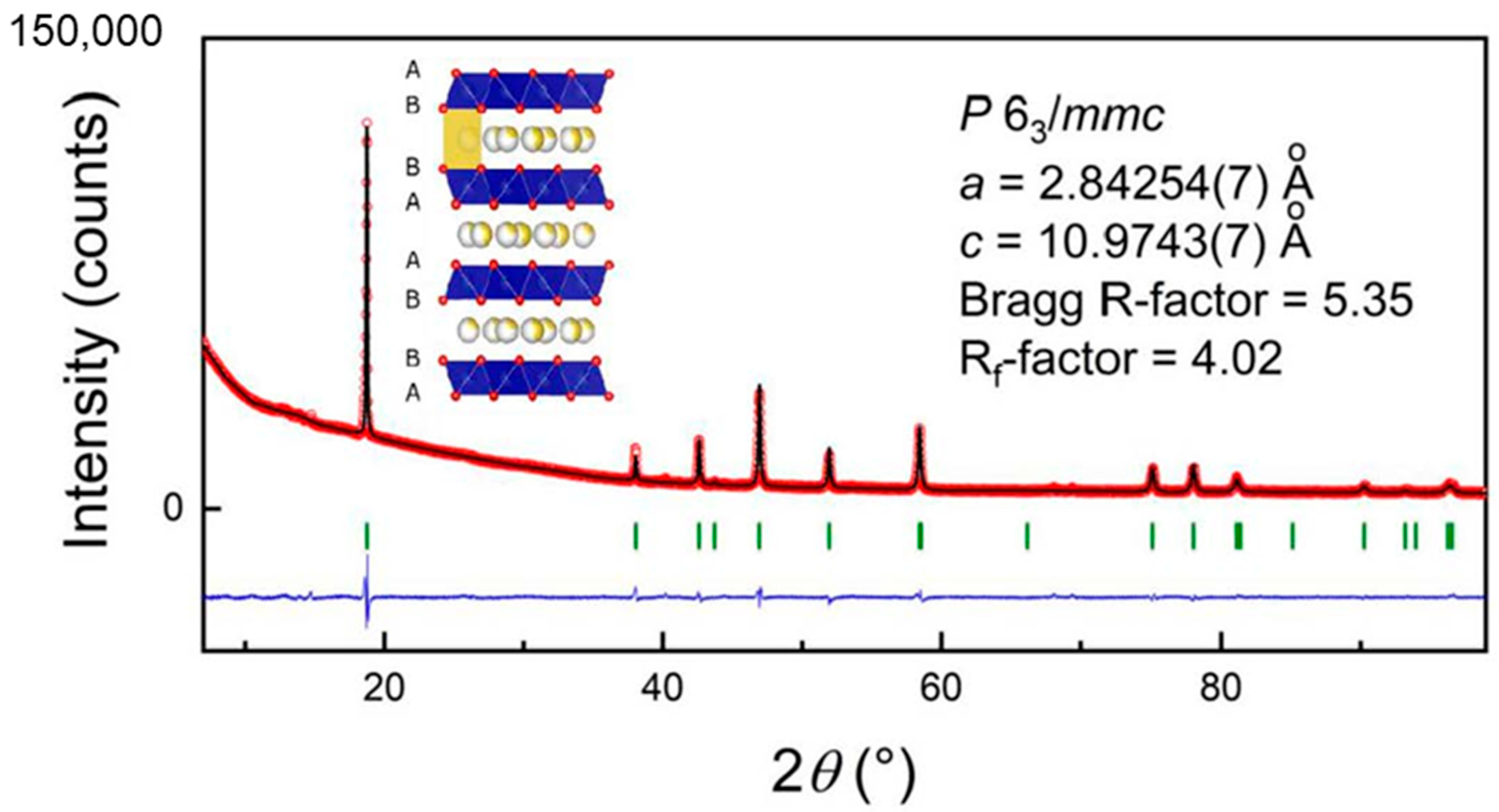
2.1. Sample Preparation and Pre-Characterization

Na0.8Co0.8Ti0.2O2 was prepared from stoichiometric amounts of Co3O4 (Sigma Aldrich, Taufkirchen, Germany, 99.99%), TiO2 (Anatase, Sigma Aldrich, 99.9%) and Na2CO3 (Sigma Aldrich, 99.9%), via a solid-state synthesis route. The mixture of initial components was ground, pressed into a pellet and held for 15 h at 900 °C in air followed by 10 h at 600 °C and rapid cooling to room temperature. After synthesis, the material was stored in a glove box with oxygen and water content less than 0.1 ppm. Phase purity was checked using laboratory XRD analysis (STOE STADI P diffractometer, Co K-radiation, ¦Ë=1.7889 Å). Chemical composition of the material was confirmed by ICP-OES analysis.

2.2. Electrochemical Characterization

Electrochemical studies were performed in two-electrode Swagelok-type cells using a VMP3 potentiostat (Biologic Instruments). Electrodes were prepared by pressing a mixture of the active material with Super P carbon (BASF) and PTFE (Aldrich) in an 80:10:10 weight ratio onto an aluminum current collector. Sodium anodes were home-made by rolling pieces of metallic sodium (Alfa Aesar, 99.95%) into plates and cutting out disks. A glass fiber cloth (Whatman, GF/D), soaked with electrolyte, served as separator. As electrolyte, 1M NaClO4 (ACS, 98.0–102.0%) solution in a mixture of ethylene carbonate (EC, 99%, BASF) and propylene carbonate (PC, 99%, BASF) in the ratio of 1:1, with adding of 5% of fluoroethylene carbonate (FEC, 99%, Sigma Aldrich) was used. Alternatively, an ether-based electrolyte, containing 1M NaPF6 (98%, Sigma Aldrich) in Diglyme (99%, BASF) was used in the half-cell setup as well.
Chemical diffusion coefficient in Na0.8Co0.8Ti0.2O2 was measured using a galvanostatic intermittent titration technique (GITT) in two-electrode Swagelok-type cells. A current pulse with a duration of 15 min at the current density of 0.2 C and subsequent waiting time of 180 min was applied in the voltage range 4.4 V–1.5 V vs. Na+/Na. The cell voltage during the experiment was varied between 2.0 V and 4.2 V. The diffusion coefficient is calculated according to the literature [25].
Electrochemical tests of full cells with the Na0.8Co0.8Ti0.2O2 cathode and a hard carbon (CARBOTRON P) anode have been carried out in two-electrode coin cells (2025) using a Basytec potentiostat in the potential window of 4.2 V–2.0 V. The cathode was prepared by coating a mixture of the active material with Super P carbon (BASF) and PVDF Solef 1013 (Solvay) in an 80:10:10 weight ratio with N-Methyl-2-pyrrolidon (NMP, 99.5%, Sigma Aldrich) onto an aluminum current collector. The anode was prepared by coating hard carbon, Super P carbon (BASF) and PVDF Solef 1013 (Solvay) in a 92:4:4 weight ratio with NMP on a copper current collector. All electrodes were punched into 16 mm disks, additionally pressed with a rolling calender and dried overnight in a vacuum oven at 120 °C. A glass fiber filter (Whatman, GF/D), soaked with electrolyte, served as a separator. As electrolyte, 1M NaClO4 (ACS, 98.0–102.0%) solution, in a mixture of EC and PC in a ratio of 1:1, with 5% FEC added, was used, similar to galvanostatic studies of half cells. Different approaches for optimization of Na0.8Co0.8Ti0.2O2 electrochemical performance were applied using protective coatings/layers on the cathode and anode surface. The cathode surface was fabricated beforehand using the Doctor Blade technique by casting the slurry containing 80 wt. % Na0.8Co0.8Ti0.2O2, 10 wt. % Carbon black and 10 wt. % PVDF (Solef 1013, Solvay) onto Al-foil. Al2O3 ALD on Na0.8Co0.8Ti0.2O2 cathodes was performed on a Savannah® S200 (Veeco). The electrodes were mounted on an aluminum sheet and then heated to 120 °C. The two half-reaction steps consisted of injecting trimethyl-aluminum (TMA, 97%, Sigma Aldrich) or H2O with a pulse duration of 15 ms and 20 s purging between each pulse. Twenty ALD growth cycles were used to prepare the Al2O3-coated cathodes. The final thickness of the Al2O3-coating was around 3.5 nm. The punched electrodes were assembled in a half cell. For the anode side, protection either with a carbon layer, or coating with Zn was applied. A thin carbon felt (~110 µm) was mechanically pressed onto a sodium chip to design a structured surface between carbon and sodium. The prepared chips were assembled in a half-cell setup. For Zn-coating, dried ZnCl2 (98%, Sigma Aldrich) was dissolved in dried THF providing a 0.1M solution, similar to the procedure described in work [26]. Punched sodium chips were put into the solution for 10 s and dried afterwards under Ar in the glove box. The reaction between Na and ZnCl2 immediately leads to the formation of metallic Zn on the Na surface, and NaCl as a product. The Zn-coated anodes were implied in a half-cell setup.

2.3. Operando X-ray Diffraction Studies

Operando X-ray diffraction measurements on Na0.8Co0.8Ti0.2O2 were performed in a transmission mode, using laboratory STOE STADI P diffractometer with Mo K-α1 radiation (¦Ë = 0.7093 Å). The home-built experimental setup represents a single coin cell holder connected to a one-channel VMP3 potentiostat. For experiments, dedicated in situ coin cells 2032 with windows of 4 mm diameter on both sides, closed by Kapton foil, were used.
In order to characterize the Na0.8Co0.8Ti0.2O2 starting material, a pattern was recorded before the electrochemical process (Na-removal and -insertion) was started. The electrochemical cell was then successively charged and discharged in galvanostatic mode at a current corresponding to the intercalation or deintercalation of 1 Na per formula unit during 20 h (0.05C rate). All diffraction patterns were analyzed by Fullprof implemented into the software package FullProf Suite [27]. The Al-foil as current collector on the cathode side served as an internal standard during the measurements, and the refined lattice parameter of Al provided an independent control of the reliability of the obtained model parameters. Two different sample shifts, for Na0.8Co0.8Ti0.2O2 and for the Al-foil, were considered in the analysis procedure.

2.4. Operando XAS Studies

Operando X-ray absorption experiments on the Co K-edge in the energy range 7560–8300 eV were carried out at the beamline P65 at PETRA III extension (DESY, Hamburg, Germany), in transmission and fluorescence setup. An 8-fold coin cell holder, coupled with a Biologic Instruments potentiostat, was utilized for the electrochemical cycling [28]. In situ coin cells similar as for operando XRD diffraction experiments were used. XANES and EXAFS data analysis was performed identically to the procedure applied in [15,29]. For XANES analysis, CoO, Co3O4 and Co(AcAc)3 were used as reference materials for Co2+, mixed Co2+/Co3+ and Co3+ valence states, respectively. For EXAFS studies, a post-edge region of 600 eV was taken into consideration. A structural model of Na0.8Co0.8Ti0.2O2 from the diffraction experiment was used as a starting approach. For data analysis, the background μ o E was subtracted from the absorption spectrum μ E and the resulting data were normalized according to the formula   χ E = μ E μ 0 E / Δ μ 0 E , where Δ μ 0 E denotes the measured jump in absorption at the edge. The normalized spectrum was converted into k space using k = 2 m E E 0 / 2 1 2 . By weighting χ k with k 3 , contributions of signals from higher k space values were amplified. The resulting k 3 χ k function was Fourier-transformed into the R space, allowing the determination of bond contributions. Least-square fits were performed using the FEFF6 code [30].

3. Results and Discussion

Na0.8Co0.8Ti0.2O2 was prepared as a single-phase material, the corresponding diffraction pattern and structural information are presented in Figure 1 and Table 1. Rietveld analysis of the structural model based on the β-RbScO2 structure (P63/mmc space group, P2-form) provided lattice parameters a = 2.84254(7) Å, c = 10.9743(7) Å, Bragg R-factor of 5.35 and Rf-factor of 4.02 with the overall temperature factor 1.88(7) Å2.

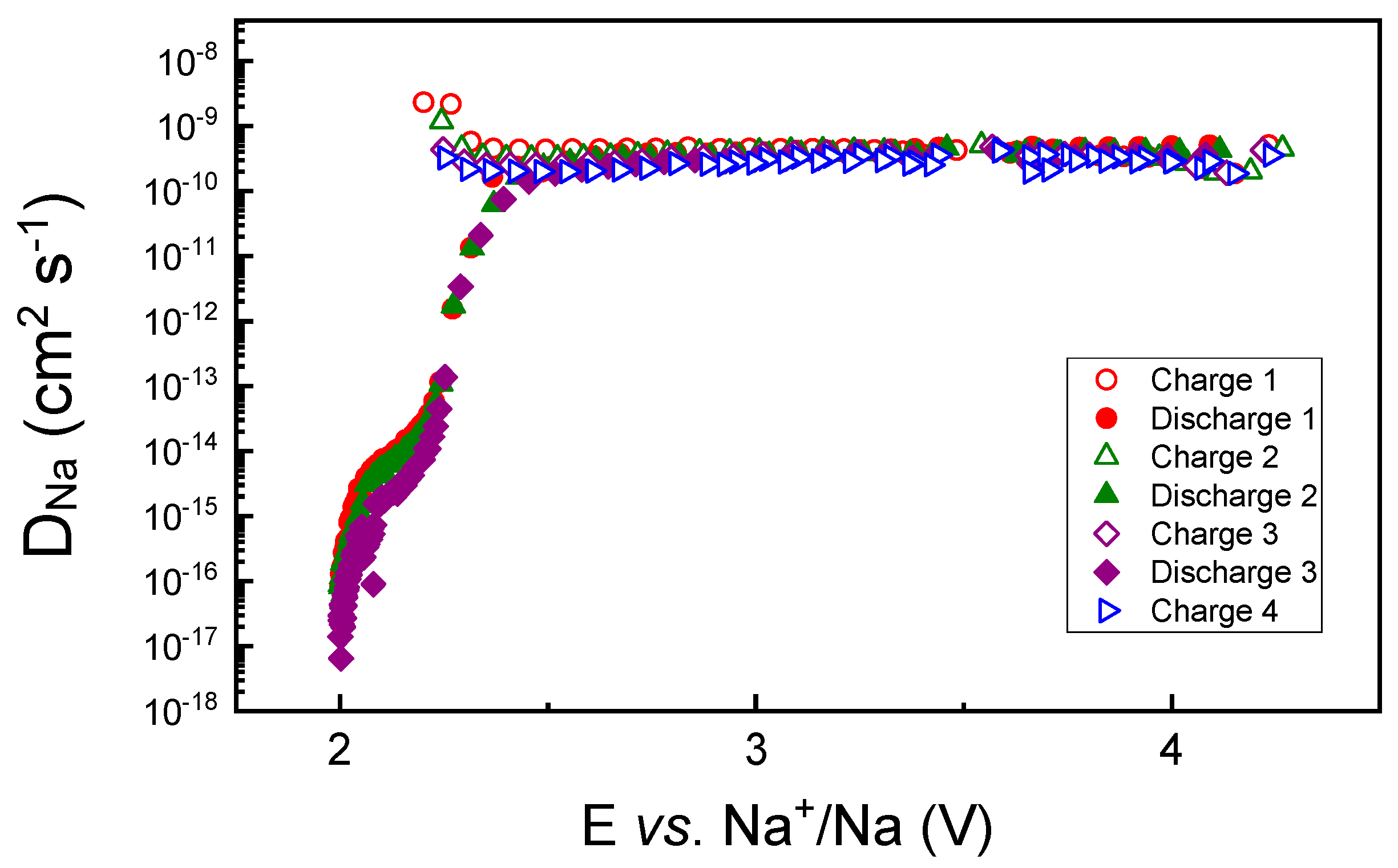
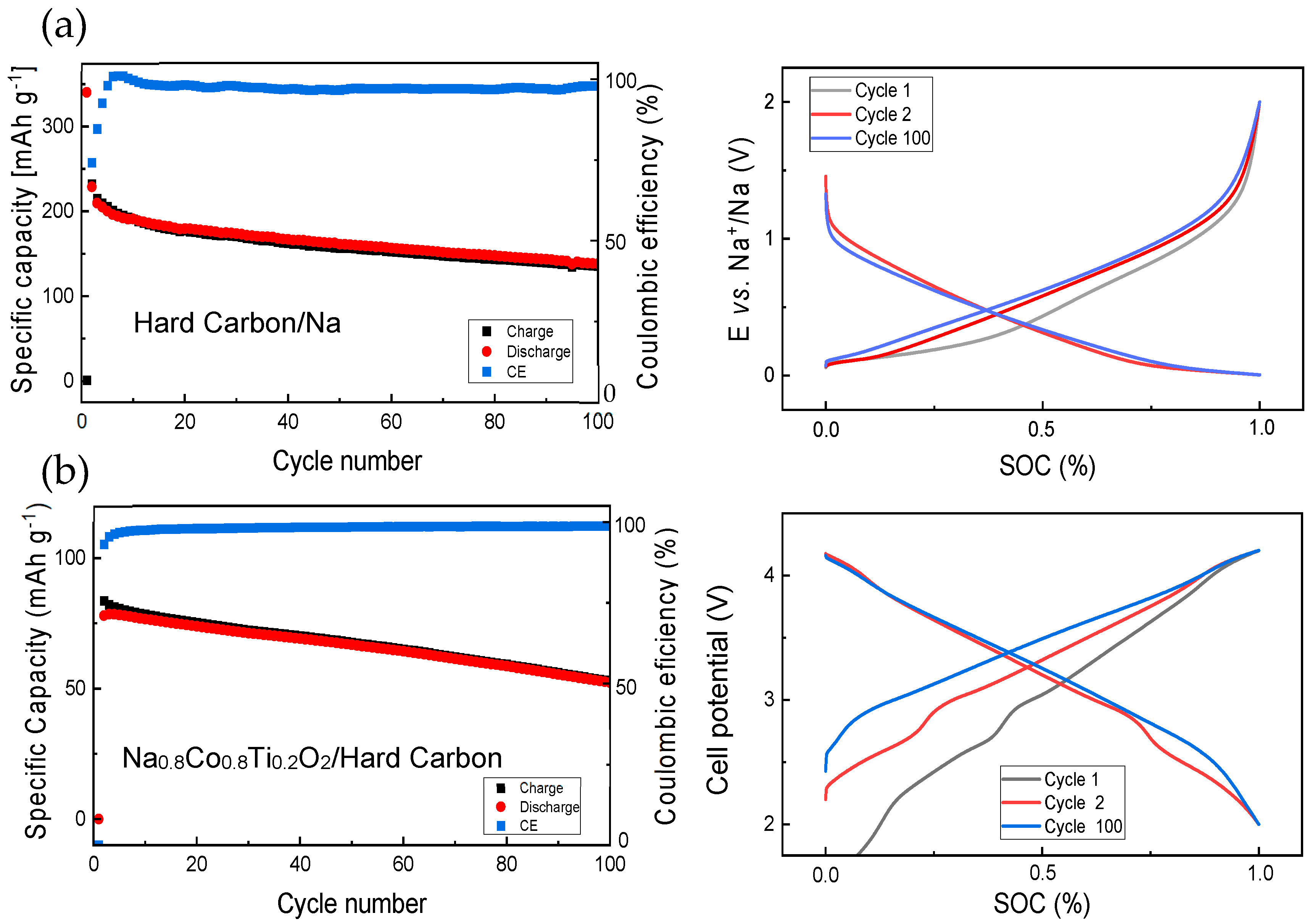
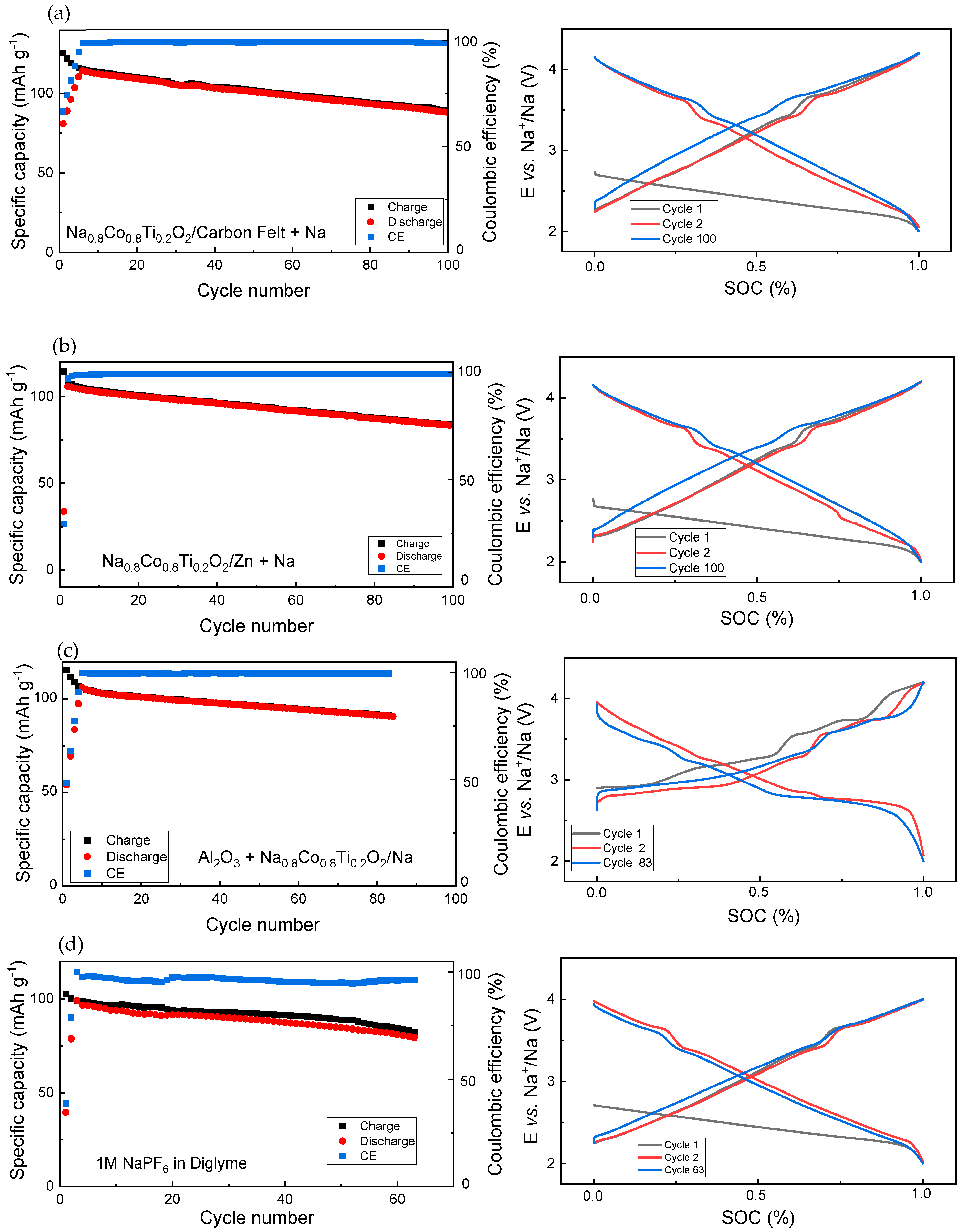
3.1. Electrochemical Studies

First, Na0.8Co0.8Ti0.2O2 was studied in Na-cells using a conventional electrolyte composition containing 1M NaClO4 in EC/PC (1:1) + 5% FEC. In order to find the optimal electrochemical performance, different potential windows were tested such as 4.2–1.8 V, 4.2–0.2 V and 4.6–1.8 V vs. Na+/Na, see Figure 2 for the charge–discharge curve in the first cycle, and capacities during the 50 cycles for these cell potentials. The capacity value of about 110 mAh g−1 corresponds to change in the Na-content Δx(Na) = 0.4 in Na0.8Co0.8Ti0.2O2.
As shown in Figure 2, the battery shows the most stable electrochemical behavior in the potential range of 4.2–1.8 V, followed by the range of 4.6–1.8 V and 4.2–0.2 V. The very low cell potential of 0.2 V vs. Na+/Na seems to be more detrimental for the Na0.8Co0.8Ti0.2O2 cathode than the high cell voltage of 4.6 V. Various phase transformations, or electrolyte decomposition on the electrode surface with a formation of a non-beneficial solid-electrolyte cathodic interface may be a reason for the observed phenomena. A differential capacity plot dQ/dE vs. E built for the first cycle, in the potential range 4.2–1.8 V, shows a multiple redox process, pointing some transformations in crystal and electronic structure (see Figure S1 in the Supporting Information).
The chemical Na diffusion coefficient in Na0.8Co0.8Ti0.2O2, determined for the first several charge–discharge cycles of the material in the Na-cell, confirms a very stable Na-removal/insertion behavior (see Figure 3). It is almost constant in a potential range between 2.5 and 4.2 V and decreases significantly below 2.35 V, close to the onset of a strong potential decrease in Figure 2. The diffusion coefficient is much higher than that measured for O3-Na0.95Co0.5Ti0.5O2 of 10−14 cm2 s−1 [15], thus confirming the higher and more stable Na mobility in the P2-structure in comparison to the O3 structure.
Prior to the study of full cells with the Na0.8Co0.8Ti0.2O2 cathode and hard carbon anode, hard carbon was tested in a half cell with a Na metal anode (see Figure 4a). Some capacity fade with a higher discharge capacity in comparison to the charge one occurs during first several cycles, resulting in a Coulombic efficiency lower than 100%. This is due to a solid–electrolyte interface (SEI) formation on the hard carbon surface. In the next cycles, the discharge and charge capacities are very close to each other. Comparison of the cell potential development for the 1st, 2nd and the 100th cycle shows noticeable difference between the 1st and the 2nd charge processes and almost no difference between the 2nd and 100th charge, pointing to a nearly constant battery polarization during long-term cycling. A full cell with Na0.8Co0.8Ti0.2O2 and hard carbon demonstrates some capacity fading with the cycling as well (Figure 4b). Evolution of the cell voltage with cycling shows a big difference between the first and second cell charge (Figure 4b, right), since the full cell shows almost a zero potential prior to the electrochemical measurements.
The next step included some protective strategies for electrodes at the anode and cathode side, with regard to the long-term cycling performance (Figure 5). For these studies, coin cells were used. The study focused on the Coulombic efficiency, which reflects the electrolyte stability in contact with the Na0.8Co0.8Ti0.2O2 and Na metal anode.
To support uniform Na deposition, carbon felt as a protective layer, and Zn coating on the Na surface were applied, see Figure 5a,b. In the case of the carbon protective layer, the first 8 charge–discharge formation cycles at the beginning of cycling were necessary for stabilizing the battery operation, since the charge capacity, corresponding to the Na-removal from the cathode and Na-deposition on the anode side, is much higher than the discharge capacity. During further cycling, charge capacity is still slightly higher than the discharge capacity. The development of the cell potential curve in dependence on the state-of-charge (SOC) replicates the curve of the cell with non-protected Na (Figure 2), thus confirming the redox inertness of the carbon protective layer.
In the case of the Zn coating, stable operation of the battery was already achieved after two charge–discharge cycles, see Coulombic efficiency in Figure 5b. During further cycling, the CE is very close to 100%, indicating a high electrolyte stability reached using this protective strategy. The SOC curve as a function of the cell potential has a redox peak during cell discharge at 2.5 V in the second cycle; however, this did not appear in the following cycles. For both the carbon layer and Zn coating, the charging curve for the 100th cycle lies slightly higher than at the beginning of cycling.
A protective Al2O3-layer was deposited on the Na0.8Co0.8Ti0.2O2 cathode, which was prepared as a coating film on the Al foil. In this strategy, the charge capacity was also significantly higher than the discharge capacity during the first several charge–discharge formation cycles. Additionally, charge and discharge curves showed several additional peaks pointing to some parasitic redox reactions, which take place in parallel to the main electrochemical reaction. Interestingly, the cell voltage during charge and discharge after 83 cycles was very close to the 2nd cycle (Figure 5c).
Using 1M NaPF6 in Diglyme as an electrolyte for the Na0.8Co0.8Ti0.2O2/Na cell without any protective measures led to a much higher charge capacity than the discharge capacity during the first several cycles, and still a higher charge capacity during following cycling, indicating a partial electrolyte oxidation at high cell potentials. Generally, battery cycling using this ether-based electrolyte was less stable than the carbonate-based electrolyte due to a less redox stability of ether-based electrolytes at cell potentials above 3.8 V vs. Na [31].

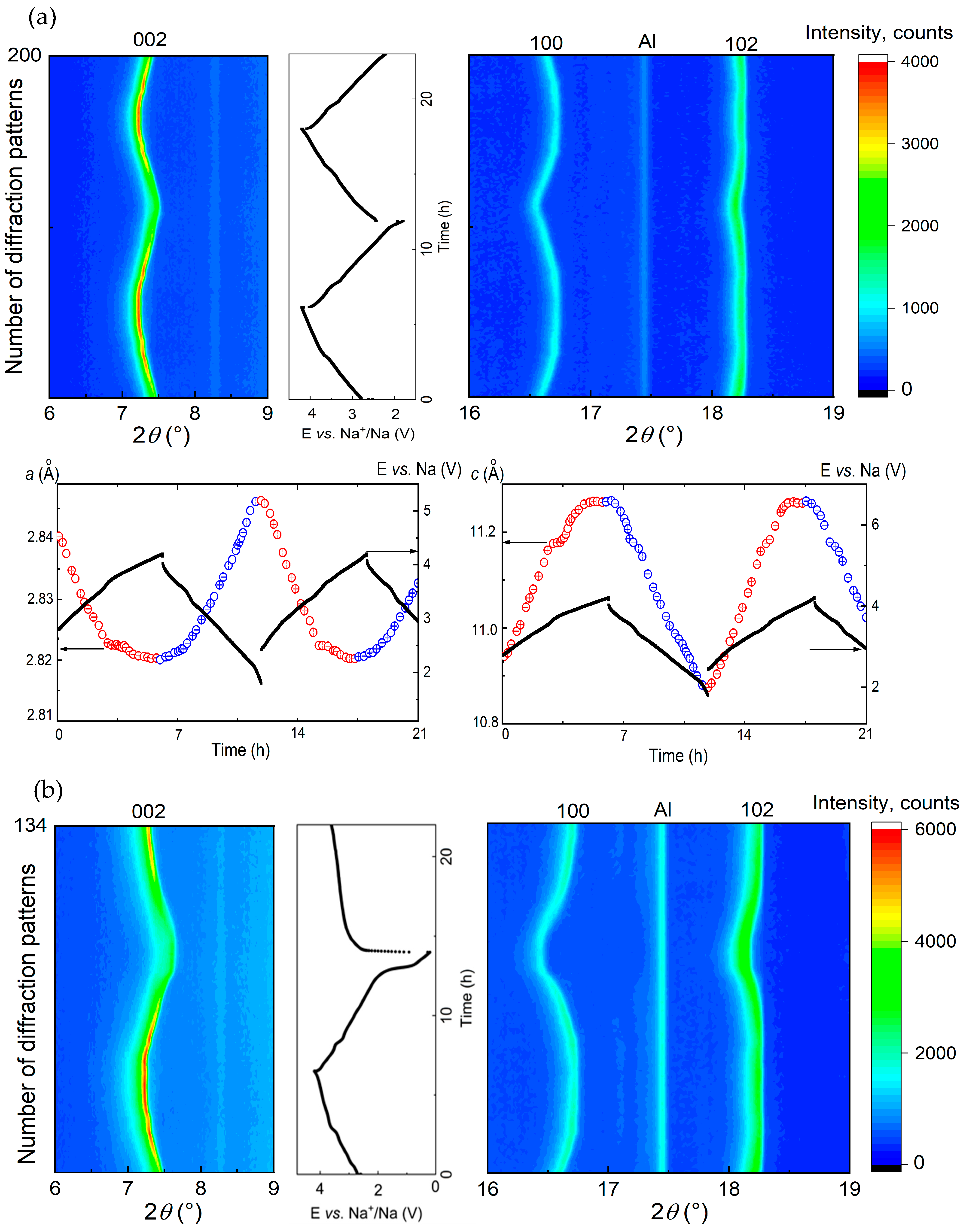
3.2. Structural Characterization Using Operando XRD Analysis

In order to understand different cycling stability in the potential windows 4.2–1.8 V, 4.2–0.2 V and 4.6–1.8 V, structural changes in the material during battery operation were studied using X-ray powder diffraction. In situ cells with the Na0.8Co0.8Ti0.2O2 cathode and Na anode were charged and discharged in the above-mentioned potential ranges while diffraction patterns have been recorded.

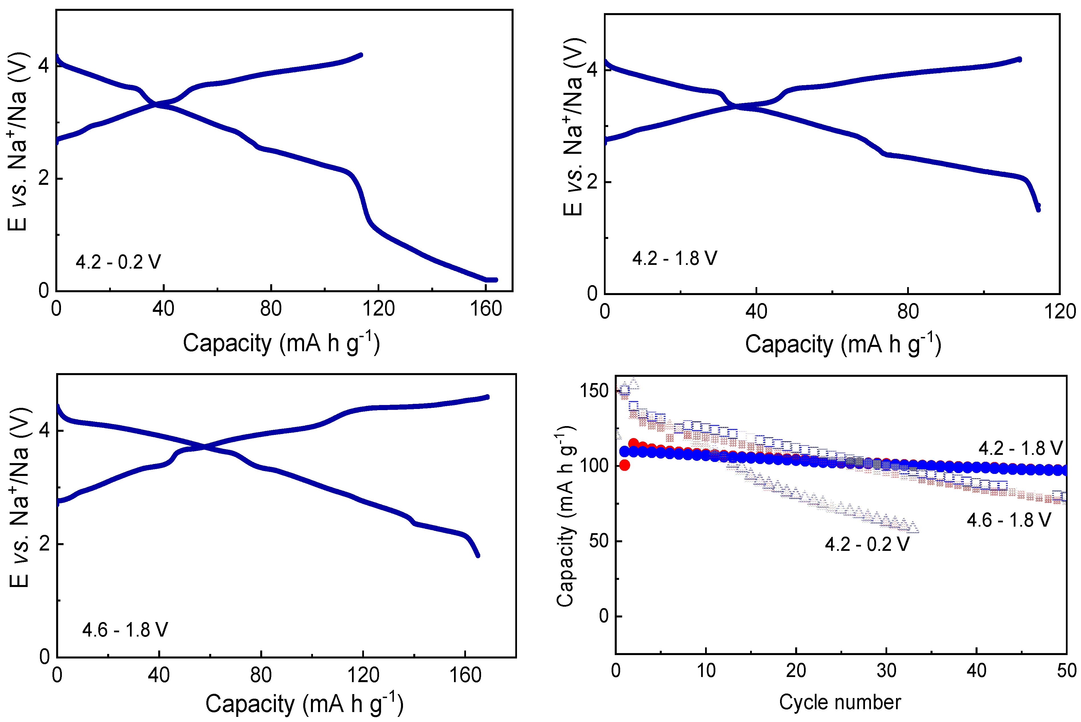
3.2.1. Voltage Window of 4.2–1.8 V vs. Na+/Na

In this potential window, Ne-removal and insertion occur mostly as a single-phase reaction mechanism, as shown in the waterfall-plots of diffraction patterns (Figure 6a). No additional reflections appeared during cell charge and discharge. During cell charge, lattice parameter a decreases, reflecting the shortening of the average (Co,Ti)-O distance, while the lattice parameter c increases due to the strengthening repulsion between neighboring (Co,Ti)O2 layers upon Na-removal (Figure 6a). A change in the slope in the cell voltage vs. time at 3.5 V during cell charge coincidences with slower changes in the cell metrics of NaxCo0.8Ti0.2O2 above this potential. The kink corresponds to the composition Na0.6Co0.8Ti0.2O2 with the average oxidation state of Co + 3.25. From the XRD data, we cannot elucidate any structural differences such as a Na/vacancies ordering between the compounds with the Na-content higher and lower than 0.6. It is possible that a very narrow multi-phase region with coexistence of two NaxCo0.8Ti0.2O2 phases with tiny structural differences can exist. However, additional comprehensive structural investigations including TEM and electrode diffraction as well as neutron diffraction are necessary to confirm this suggestion.

3.2.2. Voltage Window of 4.2–0.2 V vs. Na+/Na

Extending the voltage window down to 0.2 V during cycling leads to an increase in the specific capacity at least for the first several cycles. However, one should keep in mind that the additional capacity is not only a result of completed sodiation of Na0.8Co0.8Ti0.2O2 to x(Na) = 1.0, but also of Na intercalation into the conductive carbon black as well as solid electrolyte interface (SEI) formations. All three processes occur simultaneously below 1 V vs. Na+/Na, see Figure 2. Analysis of the diffraction data below 1 V revealed the appearance of a second phase in the cathode material, which seems to be isostructural to the initial Na0.8Co0.8Ti0.2O2, but exhibits a larger lattice parameter a and a smaller parameter c, see Figure 6b. Obviously, the second phase arises when Co3+ is reduced to Co2+. The lattice parameters of the second phase change during further Na-insertion, while the lattice parameters of the initial phase remain constant, displaying a classical two-phase reaction mechanism. A slope in the electrochemical curve instead of a plateau, which is characteristic for a two-phase process from the thermodynamic point of view, is originated from a parallel intercalation of Na cations into carbon black (see Figure S2 in the Supporting Information) and the SEI formation.

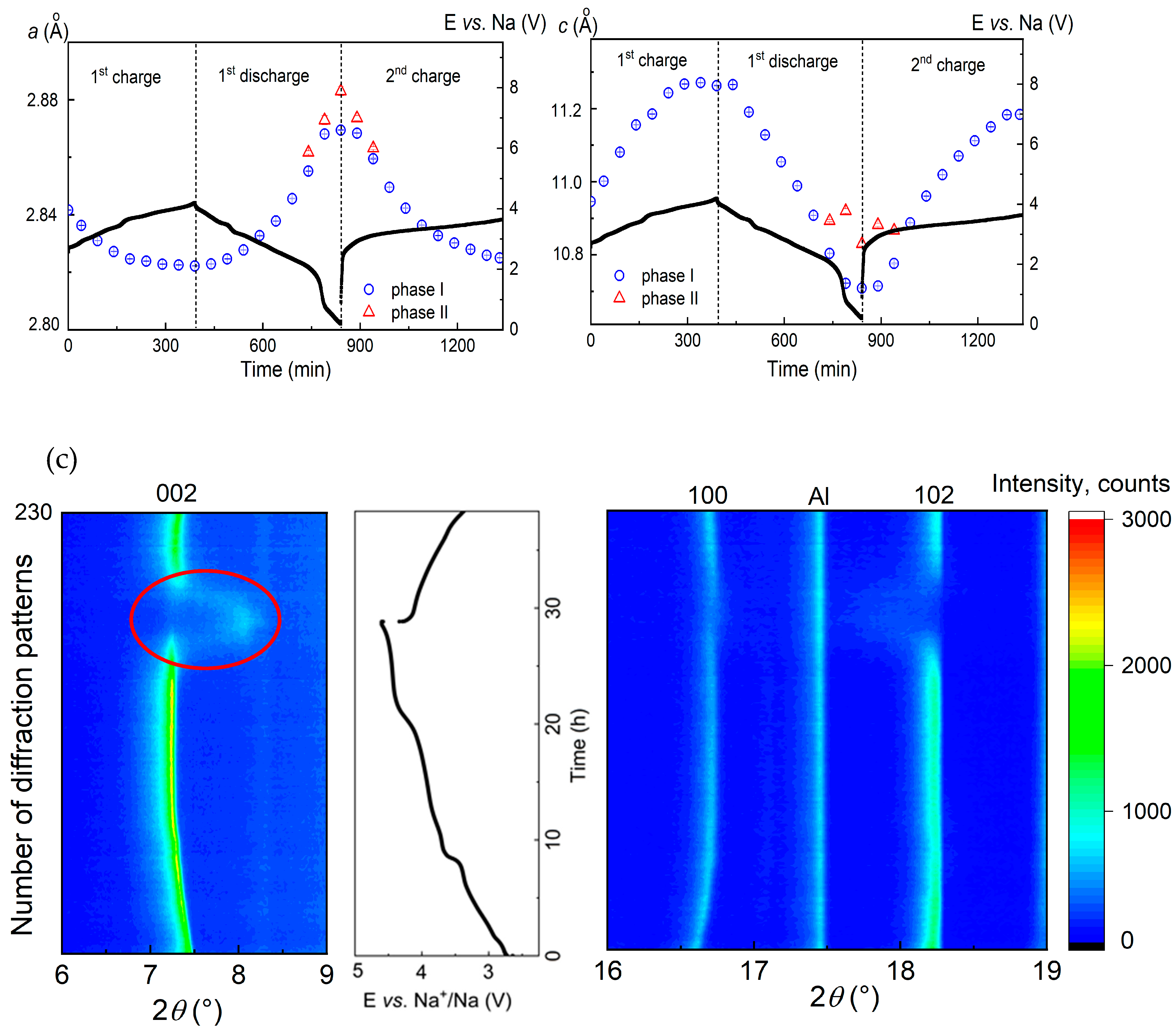
3.2.3. Voltage Window of 4.6–1.8 V vs. Na+/Na

Increasing the voltage window up to 4.6 V vs. Na+/Na led to an enhanced specific capacity of the battery and reduced its cycling stability. A continuous decrease in the intensity of the 002 reflection at 2Theta angle of 7.45° and the arising of a new broad reflection at around 8° points to a formation of a new phase at potentials higher than 4.4 V. A transformation of the P2 to O2 structure at a significant vacancy concentration is well known from the literature [32]: it is characterized by the glide of the transition metal oxide (TMO2) slabs resulting in a re-coordination of the Na sites from trigonal prisms to octahedral surrounding, and a severe contraction of the unit cell along the c-axis. This behavior resembles the structural evolution of the Na2/3[Ni1/6Mn1/2Fe1/3]O2 material: during charge, Na removal results in O-type stacking faults within the P2 structure, which continuously increase in proportion progressing towards a pure O2 structure, representing a quasi-solid-solution region “P2–O2” [33].
Since the formed O2 structure exhibits a worse crystallinity compared to the P2 structure, as the most intense reflections 002 and 102 show broadening and significant intensity loss (Figure 6c), Rietveld analysis of the NaxCo0.8Ti0.2O2 structure at electrochemical potentials higher that 4.2 V vs. Na+/Na has not been performed.

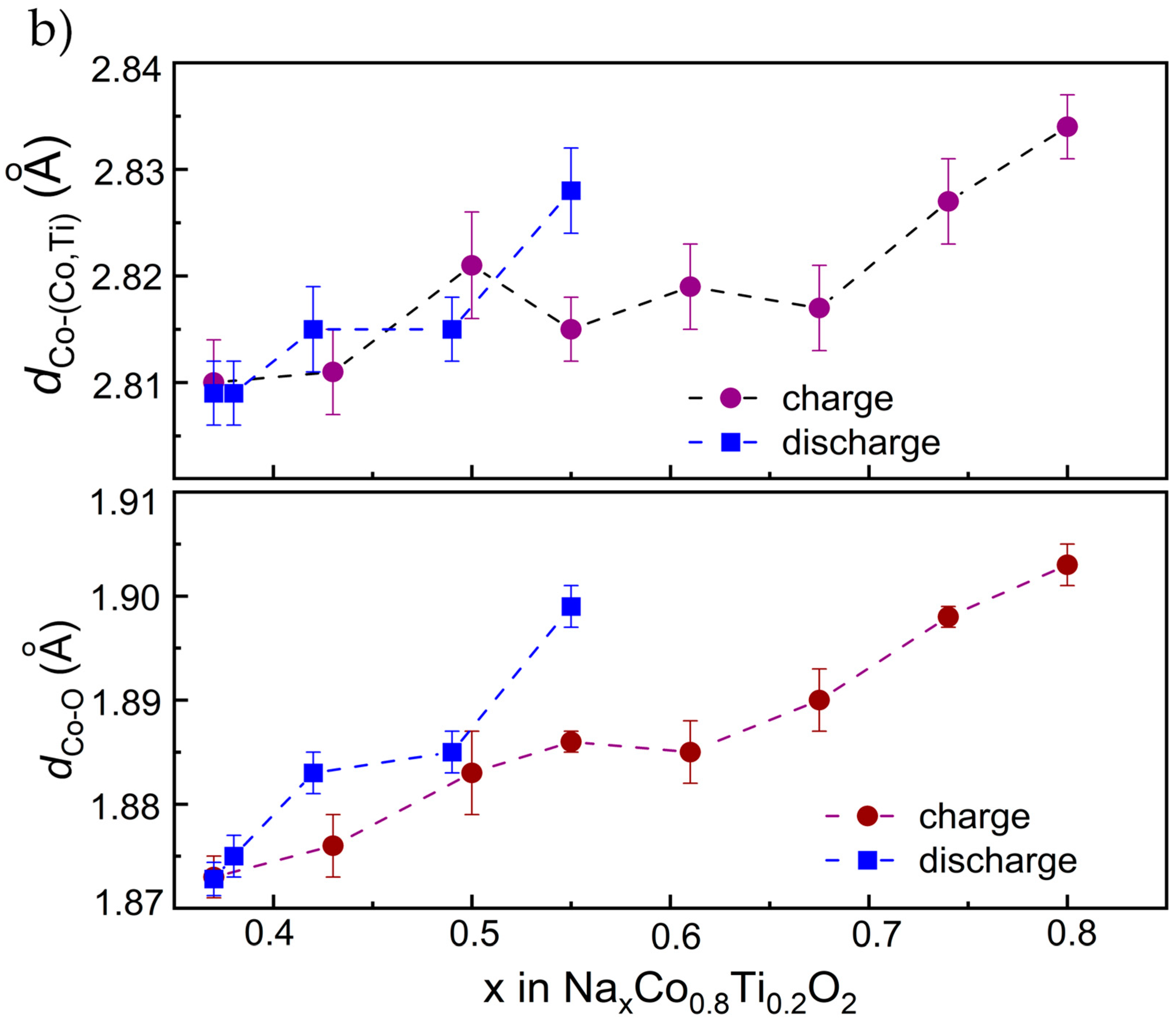
3.3. Structural Characterization Using Operando XAS Studies

In order to understand the charge compensation mechanism during Na-removal from and insertion into Na0.8Co0.8Ti0.2O2, XANES and EXAFS measurements have been performed. For XANES analysis, K-edge spectra of CoO, Co3O4 and Co(AcAc)3 used as reference materials for Co2+, Co2.66+ and Co3+, were recorded as well (Figure 7a). The spectra show a clear shift towards higher energy values during desodiation of Na0.8Co0.8Ti0.2O2 (inset in Figure 7a), indicating the oxidation of Co ions.
Since the position of the absorption edge E0 in transition metal oxides correlates with the metal valence state [34], two different approaches are usually used to directly determine the absorption edge E0: either as the energy corresponding to the maximum of the energy derivative of μ(E) [35], or as the energy at the x-ray absorption coefficient μ(E) = 0.8 of normalized post-edge intensities [36]. In the case of Co, these two approaches provide very close energy values [36]. Therefore, we defined the absorption edge E0 as the energy at μ(E) = 0.8. From these data we can conclude a Co3+ valence state for pristine Na0.8Co0.8Ti0.2O2 and further Co oxidation during Na-removal. Extraction of 0.42 Na from Na0.8Co0.8Ti0.2O2 results in a 0.7 eV energy shift in the Co K-edge position towards higher values, which is slightly lower that the corresponding difference in the Na-content for NaxCo0.5Ti0.5O2 materials [15]. Further, EXAFS analysis of the data provided Co-O bond lengths between 1.903 and 1.872 Å for the Na0.8Co0.8Ti0.2O2 and Na0.38Co0.8Ti0.2O2 compositions (Figure 7b). The bond length of 1.903 Å is in line with the interatomic distance of 1.9 Å measured for the Na0.5Co0.5Ti0.5O2 composition, in which Co formally exists as a low-spin (LS) Co3+ [15]. The decreasing Co-O distance unambiguously points to the oxidation of Co ions during desodiation of Na0.8Co0.8Ti0.2O2. The interatomic Co-Co,Ti distances decreased from 2.834 to 2.809 Å during Na-removal as well, see Figure 7b. Around ×(Na) = 0.6 in the composition dependence, both Co-O and Co-Co,Ti interatomic distances show a plateau, which may be a sign for a multi-phase reaction process. This plateau matches well with the kink in the electrochemical curve at 3.5 V as well as with the non-linear change in the lattice parameters from the operando XRD analysis. Therefore, some tiny structural transitions in Na0.8Co0.8Ti0.2O2, which are not detectable in conventional laboratory XRD measurements, but are visible with the EXAFS structural analysis, probably lead to the observed non-linear structural behavior. The whole list of the interatomic distances (Table S1) and an example of EXAFS fit for pristine Na0.8Co0.8Ti0.2O2 (Figure S4) are displayed in the SI.

4. Conclusions

Layered Na0.8Co0.8Ti0.2O2 with Co3+ adopting a P2-type structure was investigated as a cathode in Na-batteries with carbonate- and ether-based electrolytes. An optimal voltage window between 4.2 and 1.8 V vs. Na+/Na providing nearly a stable cycle life of the battery with a 110 mAh g−1 specific capacity was chosen based on electrochemical tests and comprehensive structural studies. Within this potential region, Na can be removed and inserted back into the cathode with the smallest structural changes. Increasing the charge voltage higher than 4.2 V leads to a phase transformation from the highly crystalline P2 structure to a less crystalline O2 structure. Decreasing the cut-off voltage lower than 1.8 V results in the formation of a second phase with the same P2 structure, but different cell metrics. Although in both cases a second phase is formed and growing, the potential extension below 1.8 V is more crucial for the battery performance during the long-term cycling. This might be caused by a stronger mismatch between two P2 and P2* phases than between P2 and O2, and a formation of SEI, which periodically arises during discharge below 1 V and is destroyed during subsequent charge to 4.2 V. Table 2 shows the electrochemical performance of some cobalt-containing cathode materials as well as of a commonly used Na3V2(PO4)3 cathode with a polyanionic structure from the literature, together with the results of Na0.8Co0.8Ti0.2O2: despite having a lower specific capacity of Na0.8Co0.8Ti0.2O2, the material exhibits a stable cycling behavior, which is superior to many other layered cobalt oxides.
Electrochemical tests of a full cell configuration with the Na0.8Co0.8Ti0.2O2 cathode and a commercial hard carbon anode showed the applicability of its principle. The observed capacity loss is mostly caused by the anode side, which further needs to be optimized. Alternatively, protection strategies such as surface coating were applied to the cathode and anode sides in order to facilitate the long-term cycling. Moreover, a carbon interlayer was applied as a Na metal anode protection as well. Among protective strategies, Zn coating on the Na metal anode seems to be the most promising method to improve the electrochemical capacity of the battery with Na0.8Co0.8Ti0.2O2 and Na metal anode towards long-term cycling: on the one hand, only one formation cycle is needed for battery stabilization, and on the other hand, the potential developments of the discharge curve for the second and 100th cycles are very close to each other.

Supplementary Materials

The following supporting information can be downloaded at: https://www.mdpi.com/article/10.3390/en15093371/s1.

Author Contributions

Conceptualization, D.M.; methodology, D.M.; software, B.P.; validation, D.M., B.P. and Q.L.; formal analysis, B.P.; investigation, B.P., M.V.G., A.B., D.M. and Q.L.; resources, D.M.; data curation, D.M.; writing—original draft preparation, B.P.; writing—review and editing, D.M.; visualization, K.N.; supervision, D.M.; project administration, D.M.; funding acquisition, D.M. All authors have read and agreed to the published version of the manuscript.

Funding

This work was supported by the Federal Ministry of Education and Research (BMBF) under the project “HeNa” (03XP0390C) and German Research Foundation (DFG) under the joint German-Russian DFG project “KIBSS” (448719339). M. V. Gorbunov thanks the IFW excellence program for the financial support.

Data Availability Statement

Supporting information contains a differential capacity curve for Na0.8Co0.8Ti0.2O2 during the first charge-discharge cycle, first sodiation curve for the conductive carbon black, waterfall-plots of operando XRD measurements, and fitting results for the Fourier-transformed Co K-edge EXAFS data.

Acknowledgments

This research has benefitted from beamtime allocation at beamline P65 at the PETRA III synchrotron (DESY, Hamburg, Germany). The authors thank Andrea Voss, Sebastian Lehmann and Hoang Bao An Nguyen (all IFW Dresden) for technical support.

Conflicts of Interest

The authors declare no conflict of interest.

References

  1. Deng, J.; Luo, W.-B.; Chou, S.-L.; Liu, H.-K.; Dou, S.-X. Sodium-Ion Batteries: From Academic Research to Practical Commercialization. Adv. Energy Mater. 2018, 8, 1701428. [Google Scholar] [CrossRef]
  2. Hwang, J.-Y.; Myung, S.-T.; Sun, Y.-K. Sodium-ion batteries: Present and future. Chem. Soc. Rev. 2017, 46, 3529–3614. [Google Scholar] [CrossRef] [PubMed] [Green Version]
  3. Bauer, A.; Song, J.; Vail, S.; Pan, W.; Barker, J.; Lu, Y. The Scale-up and Commercialization of Nonaqueous Na-Ion Battery Technologies. Adv. Energy Mater. 2018, 8, 1703137. [Google Scholar] [CrossRef]
  4. Delmas, C. Sodium and Sodium-Ion Batteries: 50 Years of Research. Adv. Energy Mater. 2018, 8, 1703137. [Google Scholar] [CrossRef]
  5. Kubota, K.; Kumakura, S.; Yoda, Y.; Kuroki, K.; Komaba, S. Electrochemistry and Solid-State Chemistry of NaMeO2 (Me = 3d Transition Metals). Adv. Energy Mater. 2018, 8, 1703415. [Google Scholar] [CrossRef]
  6. Sun, Y.; Guo, S.; Zhou, H. Adverse effects of interlayer-gliding in layered transition-metal oxides on electrochemical sodium-ion storage. Energy Environ. Sci. 2019, 12, 825–840. [Google Scholar] [CrossRef]
  7. Lei, Y.; Li, X.; Liu, L.; Ceder, G. Synthesis and Stoichiometry of Different Layered Sodium Cobalt Oxides. Chem. Mater. 2014, 26, 5288–5296. [Google Scholar] [CrossRef]
  8. Antolini, E.; Ferretti, M. Synthesis and Thermal Stability of LiCoO2. J. Solid State Chem. 1995, 117, 1–7. [Google Scholar] [CrossRef]
  9. Berthelot, R.; Carlier, D.; Delmas, C. Electrochemical investigation of the P2–NaxCoO2 phase diagram. Nature Mater. 2011, 10, 74–80. [Google Scholar] [CrossRef]
  10. Nazri, G.A.; Pistoia, G. (Eds.) Lithium Batteries: Science and Technology; Springer Science + Business Media: Berlin/Heidelberg, Germany, 2009; 708p. [Google Scholar]
  11. Kubota, K.; Asari, T.; Yoshida, H.; Yaabuuchi, N.; Shiiba, H.; Nakayama, M.; Komaba, S. Understanding the Structural Evolution and Redox Mechanism of a NaFeO2 –NaCoO2 Solid Solution for Sodium-Ion Batteries. Adv. Funct. Mater. 2016, 26, 6047–6059. [Google Scholar] [CrossRef]
  12. Guo, S.; Sun, Y.; Yi, J.; Zhu, K.; Liu, P.; Zhu, Y.; Zhu, G.-Z.; Chen, M.; Ishida, M.; Zhou, H. Understanding sodium-ion diffusion in layered P2 and P3 oxides via experiments and first-principles calculations: A bridge between crystal structure and electrochemical performance. NPG Asia Mater. 2016, 8, e266. [Google Scholar] [CrossRef] [Green Version]
  13. Sabi, N.; Sarapulova, A.; Indris, S.; Ehrenberg, H.; Alami, J.; Saadoune, I. Effect of Titanium Substitution in a P2-Na2/3Co0.95Ti0.05O2 Cathode Material on the Structural and Electrochemical Properties. ACS Appl. Mater. Interfaces 2017, 9, 37778–37785. [Google Scholar] [CrossRef]
  14. Sabi, N.; Doubaji, S.; Hashimoto, K.; Komaba, S.; Amine, K.; Solhy, A.; Manoun, B.; Bilal, E.; Saadoune, I. Layered P2-Na2/3Co1/2Ti1/2O2 as a high-performance cathode material for sodium-ion batteries. J. Power Sources 2017, 342, 998–1005. [Google Scholar] [CrossRef]
  15. Maletti, S.; Giebeler, L.; Oswald, S.; Tsirlin, A.A.; Senyshyn, A.; Michaelis, A.; Mikhailova, D. Irreversible made reversible: Increasing electrochemical capacity by understanding the structural transformations of NaxCo0.5Ti0.5O2. ACS Appl. Mater. Interfaces 2018, 10, 36108–36119. [Google Scholar] [CrossRef]
  16. Sabi, N.; Sarapulova, A.; Indris, S.; Dsoke, S.; Zhao, Z.; Dahbi, M.; Ehrenberg, H.; Saadoune, I. Evidence of a Pseudo-Capacitive Behavior Combined with an Insertion/Extraction Reaction Upon Cycling of the Positive Electrode Material P2-NaxCo0.9Ti0.1O2 for Sodium-ion Batteries. ChemElectroChem 2019, 6, 892–903. [Google Scholar] [CrossRef]
  17. Kang, S.M.; Park, J.-H.; Jin, A.; Jung, Y.H.; Mun, J.; Sung, Y.-E. Na+/Vacancy Disordered P2-Na0.67Co1−xTixO2: High-Energy and High-Power Cathode Materials for Sodium Ion Batteries. ACS Appl. Mater. Interfaces 2018, 10, 3562. [Google Scholar] [CrossRef]
  18. Sabi, N.; Sarapulova, A.; Indris, S.; Dsoke, S.; Trouillet, V.; Mereacre, L.; Ehrenberg, H.; Saadoune, I. Investigation of “Na2/3Co2/3Ti1/3O2” as a multi-phase positive electrode material for sodium batteries. J. Power Sources 2021, 481, 229120. [Google Scholar] [CrossRef]
  19. Watanabe, E.; Zhao, W.; Sugahara, A.; de Boisse, B.M.; Lander, L.; Asakura, D.; Okamoto, Y.; Mizokawa, T.; Okubo, M.; Yamada, A. Redox-Driven Spin Transition in a Layered Battery Cathode Material. Chem. Mat. 2019, 31, 23582365. [Google Scholar] [CrossRef]
  20. Kim, S.; Ma, X.; Ong, S.P.; Ceder, G. A comparison of destabilization mechanisms of the layered NaxMO2 and LixMO2 compounds upon alkali de-intercalation. Phys. Chem. Chem. Phys. 2012, 14, 15571–15578. [Google Scholar] [CrossRef] [Green Version]
  21. Zhao, Y.; Adair, K.R.; Sun, X. Recent developments and insights into the understanding of Na metal anodes for Na-metal batteries. Energy Environ. Sci. 2018, 11, 2673–2695. [Google Scholar] [CrossRef]
  22. Eshetu, G.G.; Elia, G.A.; Armand, M.; Forsyth, M.; Komaba, S.; Rojo, T.; Passerini, S. Electrolytes and Interphases in Sodium-Based Rechargeable Batteries: Recent Advances and Perspectives. Adv. Energy Mater. 2020, 10, 2000093. [Google Scholar] [CrossRef] [Green Version]
  23. Hasa, I.; Hassoun, J.; Passerini, S. Nanostructured Na-ion and Li-ion anodes for battery application: A comparative overview. Nano Res. 2017, 10, 3942–3969. [Google Scholar] [CrossRef]
  24. Lu, Q.; Omar, A.; Ding, L.; Oswald, S.; Hantusch, M.; Giebeler, L.; Nielsch, K.; Mikhailova, D. A facile method to stabilize sodium metal anodes towards high-performance sodium batteries. Mater. Chem. A 2021, 9, 9038. [Google Scholar] [CrossRef]
  25. Weppner, W.; Huggins, R.A. Determination of the kinetic parameters of mixed-conducting electrodes and application to the system Li3Sb. J. Electrochem. Soc. 1977, 124, 1569–1578. [Google Scholar] [CrossRef]
  26. Lu, Q.; Omar, A.; Hantusch, M.; Oswald, S.; Ding, L.; Nielsch, K.; Mikhailova, D. Dendrite-free and corrosion-resistant sodium metal anode for sodium batteries. submitted.
  27. Roisnel, T.; Rodriguez-Carvajal, J. WinPLOTR: A Windows tool for powder diffraction pattern analysis. Mater. Sci. Forum 2001, 378–381, 118–123. [Google Scholar] [CrossRef] [Green Version]
  28. Herklotz, M.; Weiss, J.; Ahrens, E.; Yavuz, M.; Mereacre, L.; Kiziltas-Yavuz, N.; Draeger, C.; Ehrenberg, H.; Eckert, J.; Fauth, F.; et al. A novel high-throughput setup for in situ powder diffraction on coin cell batteries. J. Appl. Cryst. 2016, 49, 340–345. [Google Scholar] [CrossRef]
  29. Maletti, S.; Sarapulova, A.; Schökel, A.; Mikhailova, D. Operando Studies on the NaNi0.5Ti0.5O2 Cathode for Na-Ion Batteries: Elucidating Titanium as a Structure Stabilizer. ACS Appl. Mater. Interfaces 2019, 11, 33923–33930. [Google Scholar] [CrossRef] [PubMed]
  30. Rehr, J.J.; Leon, J.d.; Zabinsky, S.I.; Albers, R.C. Theoretical X-ray Absorption Fine Structure Standards. J. Am. Chem. Soc. 1991, 113, 5135–5140. [Google Scholar] [CrossRef]
  31. Zhang, J.; Wang, D.-W.; Lv, W.; Qin, L.; Niu, S.; Zhang, S.; Cao, T.; Kang, F.; Yang, Q.-H. Ethers Illume Sodium-Based Battery Chemistry: Uniqueness, Surprise, and Challenges. Adv. Energy Mater. 2018, 8, 1801361. [Google Scholar] [CrossRef]
  32. Paulsen, J.M.; Dahn, J.R. Studies of the layered manganese bronzes, Na2/3[Mn1−xMx]O2 with M=Co, Ni, Li, and Li2/3[Mn1−xMx]O2 prepared by ion-exchange. Solid State Ionics 1999, 126, 3–24. [Google Scholar] [CrossRef]
  33. Somerville, J.W.; Sobkowiak, A.; Tapia-Ruiz, N.; Billaud, J.; Lozano, J.G.; House, R.A.; Gallington, L.C.; Ericsson, T.; Häggström, L.; Roberts, M.R.; et al. Nature of the “Z”-phase in layered Na-ion battery cathodes. Energy Environ. Sci. 2019, 12, 2223–2232. [Google Scholar] [CrossRef] [Green Version]
  34. Newville, M. Fundamentals of XAFS, Revision 1.7; University of Chicago: Chicago, IL, USA, 2004. [Google Scholar]
  35. Vitova, T.; Mangold, S.; Paulmann, C.; Gospodinov, M.; Marinova, V.; Mihailova, B. X–ray absorption spectroscopy of Ru-doped relaxor ferroelectrics with a perovskite-type structure. Phys. Rev. B 2014, 89, 144112. [Google Scholar] [CrossRef] [Green Version]
  36. Poltavets, V.V.; Croft, M.; Greenblatt, M. Charge transfer, hybridization and local inhomogeneity effects in NaxCoO2·yH2O: An x-ray absorption spectroscopy study. Phys. Rev. B 2006, 74, 125103. [Google Scholar] [CrossRef] [Green Version]
  37. Reddy, B.V.R.; Ravikumar, R.; Nithya, C.; Gopukumar, S. High performance NaxCoO2 as a cathode material for rechargeable sodium batteries. J. Mater. Chem. A 2015, 3, 18059–18063. [Google Scholar] [CrossRef]
  38. Yoshida, H.; Yabuuchi, N.; Komada, S. NaFe0.5Co0.5O2 as high energy and power positive electrode for Na-ion batteries. Electrochem. Commun. 2013, 34, 60–63. [Google Scholar] [CrossRef] [Green Version]
  39. Vassilaras, P.; Toumar, A.J.; Ceder, G. Electrochemical properties of NaNi1/3Co1/3Fe1/3O2 as a cathode material for Na-ion batteries. Electrochem. Commun. 2014, 38, 79–81. [Google Scholar] [CrossRef]
  40. Yang, P.; Zhang, C.; Li, M.; Yang, X.; Wang, C.; Bie, X.; Wei, Y.; Chen, G.; Du, F. P2-NaCo0.5Mn0.5O2 as a Positive Electrode Materia lfor Sodium-Ion Batteries. ChemPhysChem 2015, 16, 3408–3412. [Google Scholar] [CrossRef]
  41. Lu, Q.; Wang, X.; Omar, A.; Mikhailova, D. 3D Ni/Na metal anode for improved sodium metal batteries. Mater. Lett. 2020, 275, 128206. [Google Scholar] [CrossRef]
Figure 1. Structural model of Na0.8Co0.8Ti0.2O2, measured XRD pattern of Na0.8Co0.8Ti0.2O2 (red circles) together with the calculated one (black line) and the difference between them; Co K¦Á-radiation.
Energies 15 03371 g001
Figure 2. First galvanostatic charge–discharge cycle of Na0.8Co0.8Ti0.2O2 performed within different potential windows, and capacities for 50 cycles obtained during cycling within different potential windows (Electrolyte: 1M NaClO4 in EC/PC + 5% FEC). Red symbols correspond to the charge process, while blue symbols to the discharge.
Energies 15 03371 g002
Figure 3. Chemical diffusion coefficients of Na+ in Na0.8Co0.8Ti0.2O2, obtained by GITT measurements during the first several charge—discharge cycles.
Energies 15 03371 g003
Figure 4. Electrochemical performance of (a) half cells with a hard carbon electrode and a metallic Na anode, at the current density of 34.4 mA g−1 (0.1 C) and (b) full cells containing Na0.8Co0.8Ti0.2O2 cathode (13.6 mg) and hard carbon anode (8.7 mg), cycled at the current density of 0.1C calculated for the cathode amount, together with development of charge—discharge curves during selected cycles.
Energies 15 03371 g004
Figure 5. Electrochemical properties of cells with protective measures for the cathode and anode side. (a) A cell with carbon felt as a protective layer on the Na metal anode, (b) a cell with a protective Zn-coating on the Na metal anode, (c) a cell with a protective Al2O3 coating on the Na0.8Co0.8Ti0.2O2 cathode, and (d) a cell with 1M NaPF6 in Diglyme as electrolyte.
Energies 15 03371 g005
Figure 6. Contour plots of diffraction patterns for Na-batteries with Na0.8Co0.8Ti0.2O2, cycled in the potential range of (a) 4.2–1.8 V, (b) 4.2–0.2 V, and (c) 4.6–1.8 V vs. Na+/Na, together with the lattice parameters a and c, calculated from the Rietveld structural analysis. Due to the low crystallinity of Na0.8Co0.8Ti0.2O2 above 4.4 V because of the phase transformation, Rietveld analysis was not possible for this high potential range. The reflection at 2Theta value of 17.5° belongs to Al as a component of the electrochemical cell.
Energies 15 03371 g006aEnergies 15 03371 g006b
Figure 7. (a) X-ray absorption near edge structure (XANES) at the Co-K edge during charge of Na0.8Co0.8Ti0.2O2, together with the spectra of reference materials CoO, Co3O4 and Co(AcAc)3. (b) Changes in Co-(Co,Ti) and Co-O interatomic distances in Na0.8Co0.8Ti0.2O2 upon Na-removal and insertion, evaluated from in situ Co-EXAFS experiments. The coordination spheres up to 3.1 Å were considered for the calculations. Detailed fitting results are given in Table S1.
Energies 15 03371 g007aEnergies 15 03371 g007b
Table 1. Structural model of Na0.8Co0.8Ti0.2O2.
AtomWyckoff-PositionxyzOccupancy
O4f0.666670.333330.0885(6)1
Co2a0000.8
Ti2a0000.2
Na(1)2b000.250.20(1)
Na(2)2c0.333330.666670.250.60(1)
Table 2. List of cobalt-containing layered cathode materials for Na-batteries and their electrochemical performance. For comparison, electrochemical performance of a commonly used Na3V2(PO4)3 cathode with a polyanionic structure is presented as well.
MaterialCapacity (after N Cycles)Current Density (C-Rate)Potential Range, VReference
P2-NaxCoO2110 (50)0.12.0–4.2 [37]
O3-NaCoO2130 (30)0.052.0–4.0 [38]
O3-NaFe0.5Co0.5O2140 (50)0.052.5–4.0 [38]
O3-NaNi0.3Co0.3Fe0.3O2135 (20)0.22.0–4.2 [39]
P2-NaCo0.5Mn0.5O2120 (30)0.11.5–4.15 [40]
P2-Na0.67Co0.95Ti0.05O2106 (100)0.12.0–4.2 [13]
P2-Na0.67Co0.5Ti0.5O2100 (50)0.12.0–4.2 [14]
Na3V2(PO4)375 (200)1.01.5–3.5 [41]
P2-Na0.8Co0.8Ti0.2O2100 (50)0.12.0–4.2This work
Publisher’s Note: MDPI stays neutral with regard to jurisdictional claims in published maps and institutional affiliations.

