1. Introduction
Electrical power systems have passed through a paradigm shift concerning generation infrastructure in the last few decades, moving from huge, concentrated power plants to smaller distributed units, integrating autonomous grids near energy customers. As a consequence of this shift, a greater integration of distributed generation plants (especially the ones based on renewable sources) is expected, along with improvements in the efficiency, reliability, and security of distribution networks. As a result, in recent years, the participation of renewables-based energy systems in both grid-connected and islanded forms has increased dramatically [
1]. Furthermore, the exploitation of primary renewable sources to attend to local loads has favored the dissemination of microgeneration and the supply of isolated communities and consumers [
2]. In this context, microgrids (MGs) arise as novel models leading to more reliable and resilient distribution systems, taking place as central components in the ongoing process of power system decentralization.
An MG may be defined as a group of interconnected loads and Distributed Energy Resources (DERs) within a clearly defined electrical border and viewed by the grid as a single and controllable entity capable of connecting and disconnecting from the grid allowing, therefore, grid-connected and islanded operation modes [
3,
4].
The most common types of DERs in MGs are renewable power plants, whose energy production is variable, and dispatchable sources such as fossil fuel generation sets and energy storage systems [
5,
6]. These resources may be applied to support a variety of loads considered as a priority or not, making MGs capable of supplying several applications such as:
- (a)
- (b)
A condominium or complex [
8,
9]:
- −
of companies (a business or industrial complex, a shopping mall, a manufacturing facility);
- −
of residential customers (housing, a residential building complex or community complex);
- (c)
Isolated communities and installations [
10] (inhabited islands, remote research centres such as those in Antarctica, national security and environmental monitoring stations, ships, space monitoring centers, etc.);
- (d)
Military defense facilities and assets [
11].
The Alcântara Space Center (ASC) is a military installation of the Government of Brazil that works as a launching facility, subjected to the Brazilian Space Agency and operated by the Brazilian Air Force. The proximity to the equatorial line facilitates the launching of geosynchronous satellites. Due to its nature, this application displays vital requirements not only for high resilience and operational security, which take precedence in the most critical operating scenarios of launch campaigns, but also for power quality and reliability. Therefore, it can be considered a critical infrastructure facility.
1.1. Critical Infrastructure
Among several applications that MGs may attend, some come with more significant and specific requirements, as in the case of critical infrastructure installations. Governments use the term ’critical infrastructure’ to identify critical sectors whose assets, systems, and networks (physical or virtual) are considered vital to a country. Their shutdown, destruction, debilitation, or incapacitation would result in a harmful effect on a society and its economy. Classical examples of critical infrastructure include [
12]:
Transportation systems;
Security services;
Water supply;
Public healthcare system;
Electric power generation, transmission, and distribution;
Databases: economic, financial, and social security systems, among others;
Communication, climate, and seismic monitoring systems;
Military facilities;
Embedded systems (e.g., ships, airplanes, space crafts, satellites).
These essential installations and systems must be resilient to natural phenomena, accidents, terrorist and cyber attacks, and war events. The operational security of critical infrastructure sectors became a concern worldwide after the terrorist attacks whihc occurred on 11 September 2001, in the USA. The US Government has since published a series of internal guidelines that include a national plan to guarantee critical installations’ security. This plan considered the cooperation of federal, regional, and local agencies with private initiative sectors and other entities [
13].
Similarly, the European Union also developed its security program to ensure that security levels suited its critical infrastructure, to reduce failures and to provide the fast recovery of services. Consequently, in 2006, the European Commission published a guideline determining that its members should adopt specific directives in their national statutes. Likewise, the United Nations also published recurrent resolutions encouraging its members to perform coordinated efforts, through international cooperation towards developing strategies to protect their critical infrastructures, focusing on terrorism prevention and initiatives for security preparation and interoperability.
The US Government already recognizes such applicability of MGs, being part of a strategic plan that involves the economy, police and military security, and other related sectors. In Brazil, this issue increased in importance in 2006, after attacks executed by a criminal organization on several installations belonging to the state of São Paulo [
13]. These events led the Government of Brazil to officially identify the country’s priority infrastructure that should be protected in the case of new occurrences. In this context, MGs present themselves as candidates to aggregate resilience to countries’ critical infrastructures, thus providing a strategic application for society’s development The concept of a mission-critical MG was developed to attend to these requirements.
1.2. Mission Critical Microgrids
Mission critical MGs (MCMGs) are specifically designed to attend to the requirements of critical infrastructure applications, and one prominent application of MCMGs is supplying military facilities [
14,
15].
Military MCMGs specifically are primarily designed to address demands for high reliability, resilience, cyber and operational security [
16,
17]. Other applications for these MCMGs are reducing electricity bills and reducing fossil fuel consumption, reducing pollutant emissions, and achieving greenhouse effect goals. These objectives may be achieved with renewable and dispatchable power sources.
From 2011 to 2015, the US Department of Defense executed the SPIDERS program. This initiative involved the implementation of three MCMGs in different military installations, namely, Joint Base Pearl Harbor-Hickam, Hawaii (phase 1), Fort Carson, Colorado (phase 2), and Camp Smith, Hawaii (phase 3) [
11]. This program addressed four critical requirements for the target MCMGs: (i) protection of critical assets from outages due to cyber-attacks; (ii) integration of onsite DERs to supply critical assets in emergencies; (iii) sustain critical operations during prolonged conventional utility power losses, and; (iv) manage local power supply infrastructure to reduce energy consumption costs and the use of fossil fuels. In addition to these, the main achievements conquered with SPIDERS MCMG’s implementation include fully loaded black start capability and power export to utility grid and enhanced performance to capture, monitor and data log vital MCMG’s statistics to support seamless internal power supply transition activities [
11].
The MCMG of the Fort Belvoir US Army military base was designed to reduce costs of energy consumption and sustain critical moments of operation. It was evaluated as a reliable and resilient solution for military missions and also as a replicate model for future military installations [
18]. According to suppliers, the DERs alone of this MCMG are capable of resiliently providing energy to Fort Belvoir for at least fourteen days [
19].
Other examples of MCMGs for military applications reported in the literature are the US Navy Guam Naval Base and the Marines’ Combat Center of 29 Palms, California. These MCMGs increased power supply resilience and security through the use of redundant energy sources [
20,
21]. According to supplies reports, recent improvements in the 29 Palms MCMG were accomplished to maximize the use of renewable sources and perform a more efficient use of dispatchable generator sets, providing uninterrupted energy supply to critical installations [
22].
Similarly, the Parris Island MCMG was designed to guarantee a reliable and secure power supply and reduce operational costs for this military base. This MG accounts for diverse power sources that include a solar photovoltaic (PV) plant, a combined heat and power plant (CHP), a battery energy storage system (BESS), and diesel generators (DGs). In addition, the Parris Island installation was designed to ensure non-stop operation, even with the occurrence of external grid faults [
23]. Some recent cases of MCMGs worldwide (whether already operational or in the process of implementation), focusing on their main applications/findings, loads served, and other additional specific information are listed in
Table 1. It is important to note that information about military MGs are usually limited or classified because of the confidentiality required by the involved clients.
Considering the emergence of military MGs and the requirements and particularities of the ASC, this article describes in detail the conception and deployment of an MCMG specifically designed to address the requirements and particularities of this Government launch center in Brazil. The work presented here describes the proposed MCMG topology and the specific functionalities required for its application. Supply resilience and operational security are mandatory demands that should guide the capacities and operation modes assumed by this MCMG energy management system [
24,
25,
26,
27].
2. ASC-Grid: Proposed Topology
The proper MG infrastructure depends on its applications, and some degree of technological complexity may also be considered. MCMGs, for example, must comply with specific power security exigencies. Thus, the MG design to attend the ASC requirements, referred to as ASC-Grid, may be included in this category. The requests for this MCMG are:
Power supply resilience;
Secure and uninterrupted operation during launch campaigns;
Pollutant emission reduction goals;
Costs reduction with energy purchase;
Contribute towards ASC internal grid power quality and reliability.
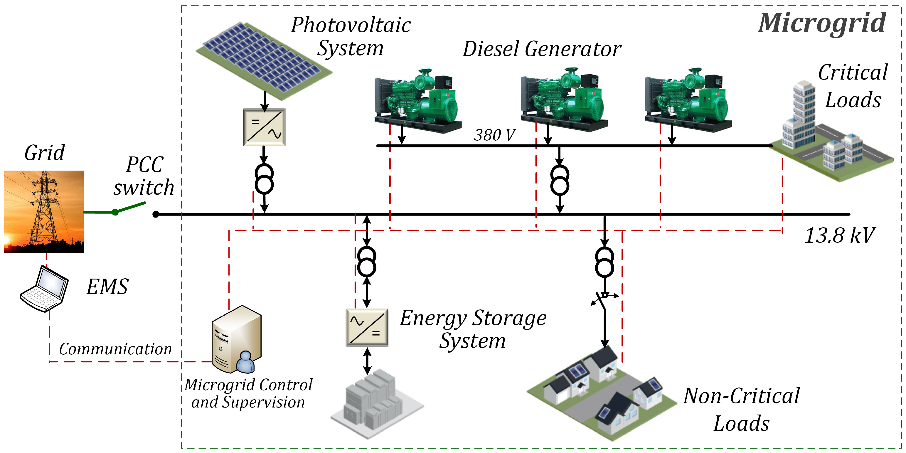
The proposed topology of the ASC-
Grid is illustrated in
Figure 1, and it is composed of a 1.25 MWp PV plant, a 1 MW/1 MWh li-ion BESS, and three 338 kVA/270 kW diesel generators (DGs) operating in Prime regime. The ASC-
Grid can connect or disconnect from the utility grid through the point of common coupling (PCC) switch. Since the peak load is estimated at 560 kW, the ASC-
Grida has a significant oversizing of its power generation capacity related to its load, namely, 3.23 times greater without BESS and 5.0 times with BESS fully charged. This intentional asymmetry between generation and load makes the ASC-
Grid capable of supporting possible single generation sources contingencies (or
contingencies). In ordinary conditions, the on-grid operation will be mainly managed by renewable sources, i.e., BESS and the PV plant. However, the use of DGs (even in its minimum allowed capacity) is necessary to provide operational security, although it is undesirable from an environmental point of view.
The ASC is comprised of highly critical installations and assets that demand a reliable and resilient supply system operating within international power quality ranges and limits. Power supply resilience and operational security requisites are more rigorous during launches when specific operational conditions occur as the intentional and mandatory disconnection of ASC from the local utility grid causes it to operate in programmed off-grid mode. This programmed disconnection is part of the ASC internal protocol that must be followed for launch campaigns. Relying only on the local utility energy, a power outage or interruption caused by an external fault may damage the launch vehicle and its useful load, leading to high financial losses and diminished client confidence. Low tolerance to failure and the elevated costs involved mainly in launch campaigns reinforce the particular exigencies of this application.
3. ASC-Grid: Characterization of Operational Scenarios
The ASC-Grid will have to operate in two typical scenarios:
During launch campaigns (highly critical short-time events);
The remaining time or out-of-launch periods (where administrative, planning and maintenance activities are executed).
Financial risks are undoubtedly higher in launch scenarios than in the remaining time. However, despite the use of pollutant sources (unwanted from the environmental point of view but necessary to guarantee operational security), the accumulated time duration of launch campaigns is considerably short, over a year, for example. Thereby, financial and environmental criteria can be reasonably compensated during out-of-launch periods, when renewable onsite generation sources are responsible for supporting the ASC internal grid, contributing to lower energy purchase bills, and avoiding greenhouse gas production. Nevertheless, even during launches, the ASC-Grid renewable sources can be used to reduce the economic and environmental impacts, supplying most of the ASC load and reducing diesel consumption without compromising power quality, reliability, and operational security. It is important to note that the ASC launch campaigns are currently sustained only by old and inefficient DGs. With the implementation of ASC-Grid, new and more efficient DGs will be installed to increase resilience and support contingencies.
3.1. ASC-Grid Operation Modes
3.1.1. Grid Connected Operation Mode—(On-Grid)
In this operation mode, the ASC-Grid is connected to the utility grid through the PCC switch, which is closed in this scenario. In this condition, the MG has significant excess power produced by the PV plant and injected into the grid. As a result, the energy purchased from the local utility will be lesser in this scenario. This scenario allows energy management strategies such as peak shaving and energy arbitrage, exploration of PV plant, and BESS capacities while meeting the limits and conditions imposed by the contract agreed between the client and the utility. Furthermore, other strategies that take advantage of renewable sources’ potential can be explored, such as reactive power regulation, variable sources integration, generation smoothing, and renewables shifting. All of these strategies bring technical, economic, and environmental benefits.
3.1.2. Islanded Operation Mode (Off-Grid)
This mode is associated with launch campaigns and planned and unplanned islanding (in case of internal or external faults). Generation sources’ redundancy, which is necessary to ensure uninterrupted power supply (even in contingencies), implies more significant investments and energy production costs. It may not eventually contribute to lower greenhouse emissions due to sources based on pollutant fuels such as DGs. This trade-off between two apparently conflicting goals, namely, pollution reduction and operational security, can be treated as a classical optimization problem.
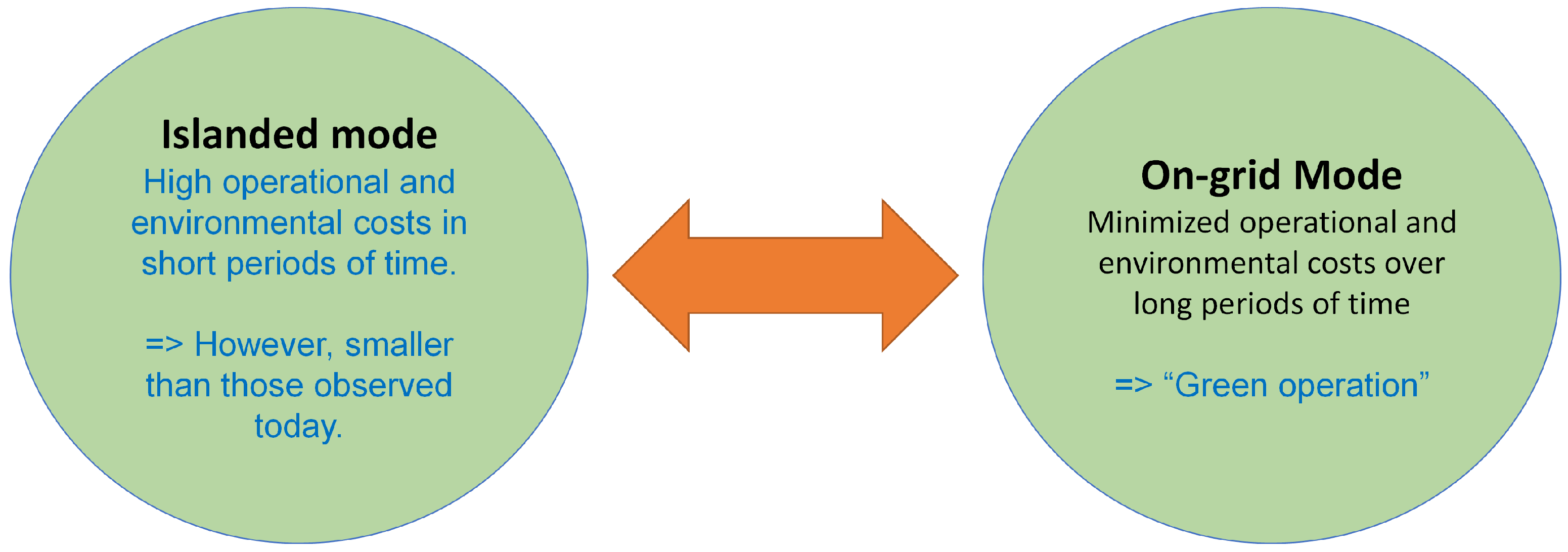
3.1.3. Expected Economic and Environmental Benefits with ASC-Grid Implementation
Due the necessity to guarantee resilience to
contingencies, operational costs of the off-grid operation are increased if compared with a traditional MG. These costs, along with the CO
emissions, must be analyzed globally, i.e., considering a whole year of operation and the number of hours in which the launch campaigns occur, which is known to be small compared to the remaining time. Therefore, considering the difference between these distinct periods, the economic and environmental impacts assumed in off-grid mode can be fully compensated in the on-grid, out-of-launches, greater interval when these demands take precedence. These two distinct frameworks of ASC-
Grid operation, with their specific benefits, are depicted in
Figure 2.
A comparison of the costs and CO
emissions, considering the current non-resilient and less secure ASC supply scenario and the future scenario with the ASC-
Grid fully operational, is presented in
Table 2. Note that, with this MCMG, there are significant economic and environmental gains, while resilience and secure operation requirements are fulfilled. In addition to increasing operational security, the Launch Center has an annual energy cost reduction of around
.
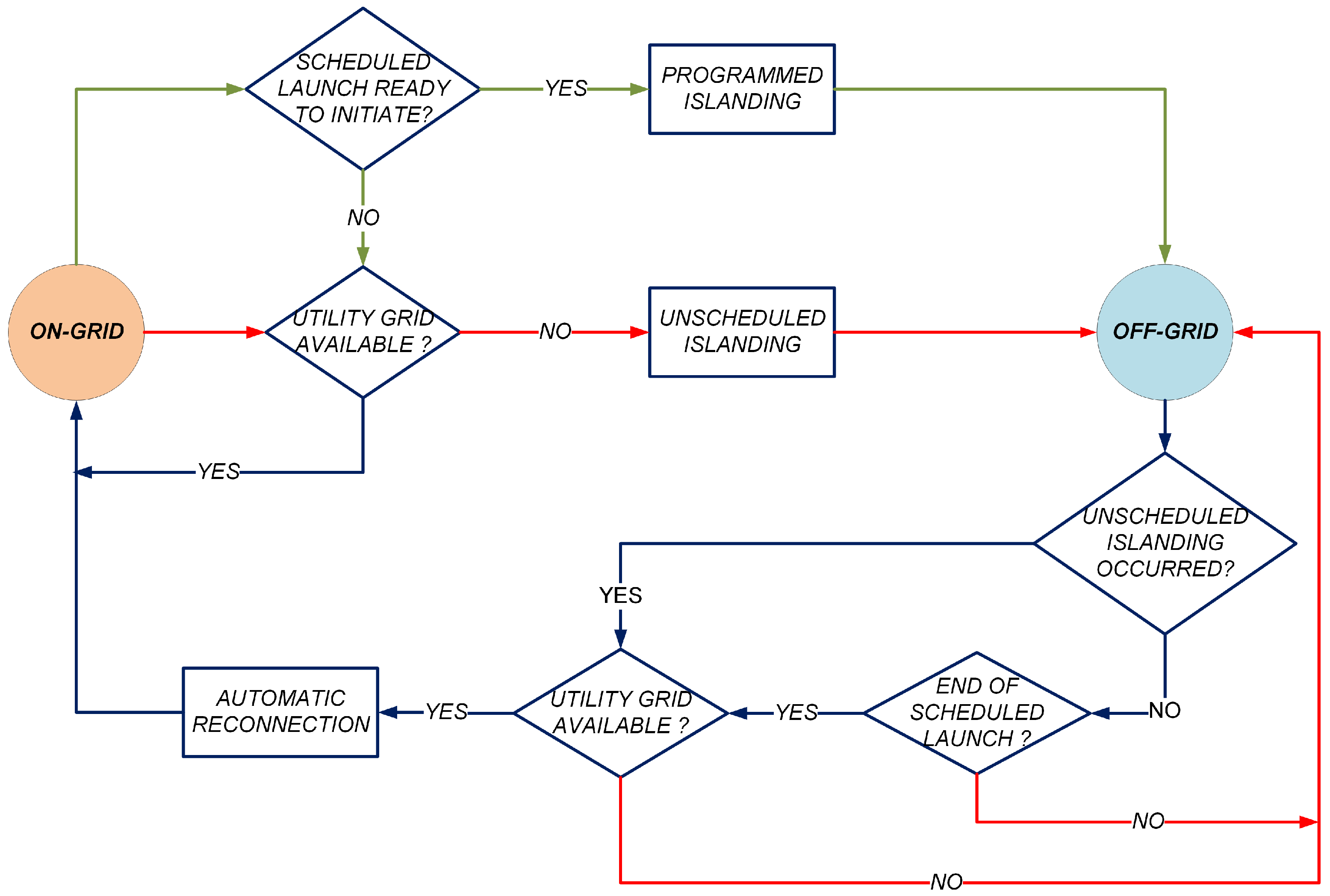
3.2. Transitions between ASC-Grid Operation Modes
Transitions are critical processes that impose requirements (e.g., minimum specifications, ride-through capacities, time responses) for MG components and their protection system. Additionally, they require sequential actions and dynamic responses compatible with each operation condition imposed by the MG energy management system. ASC-
Grid possible transitions between on-grid and off-grid modes (and vice-versa) are illustrated in
Figure 3.
In the design of ASC-
Grid transition modes, recognized international standards applicable to MGs, such as IEEE Std 2030.7-2017 [
30] and IEEE 1547-2018 [
31], were used as references. These standards consider the technical criteria of transitions’ performance, with particular attention to some parameters such as voltage, phase angle, and frequency within limits specified by the utility energy manager.
4. ASC-Grid Off-Grid Operation Modeling
This operation mode is critical, requiring energy sources redundancy to manage contingencies ensuring operational security and resilience. The security and operational constraints of each DER must be considered when the ASC-Grid is working off-grid. The actual capacities of each generation and storage source must be continuously monitored. It is important to note that the PV plant injection setpoint at a given instant is not a guaranteed value in the generation-demand balance due to the variability of this source.
The mathematical formulation of the ASC-
Grid off-grid operation is as follows. This formulation is described as a discrete dynamic optimization problem. The intended goal is to reduce diesel consumption (lower emissions) while considering
contingencies of energy generation and storage sources:
where
T refers to the total time interval considered,
is the total number of generating units (in this case
),
and
represents the associated cost with the
i-th generation unit and its output power in the time interval
t. The power balance at interval
t:
where
is the power injected or absorbed by BESS at time
t,
is the power injected by the PV plant at time
t,
and
are the total power demand and total losses at time
t, respectively.
,
and
represent the lower operational limits of the generating units, batteries and state of charge, respectively, and
,
and
represent their upper limits.
and are the voltage limits; and represent the minimum and maximum thermal capacity limits of distribution lines and transformers, respectively. is the number of transformers and the distribution lines. is the power output of unit i at time and and are the upper and lower ramp limits of unit i, respectively.
If , it indicates that BESS is discharging. Otherwise, if , BESS is charging. The variable is binary and determines the occurrence of contingency scenarios. If ∀i, the base case operation is represented (the power supply system is intact and fully operational). For one, and only one i, and all remain equal to zero, the respective generation or storage unit leaves the balance equation, representing the contingency of that unit.
The decision for a simulation on a discretization basis (e.g., seconds, minutes) will depend on the precision level required. Thus, for the ASC-Grid case, the algorithm formulation of this MCMG operation simulation in off-grid mode will be presented here in detail, considering situations with and without contingencies, i.e.,
Regular operation (base case), with all generation and storage sources operative, and;
Cases with contingencies of a single ASC-Grid DER.
The ASC-Grid operation simulation is performed in discrete form and emulated considering a time scale with the integralization of 60 s intervals.
4.1. Feeder and Branch Contingencies
Feeder and branch contingencies were not considered in the ASC-Grid off-grid operation due to the following:
The ASC internal distribution network involves short distances with few branches;
The ASC internal grid and respective equipment are subjected to an efficient preventive maintenance program;
In off-grid mode, there is a strict monitoring protocol of internal power supply infrastructure operating conditions.
Therefore, one can comfortably assume the distribution network as “safe” (from the MG perspective) during periods of off-grid operation. Moreover, it is essential to note that ASC is a military installation located in an isolated location, with rigid restrictions for access and activity within its respective area. In addition, there are no trees or vegetation near ASC internal grid lines or equipment.
4.2. Single Generating or Storage Unit Outages
One of the dispatchable DERs (DG unit or BESS) must act as grid forming in off-grid operation. In order to meet contingency scenarios, at least two ASC-Grid dispatchable sources must be available and fully operational. BESS will be the grid former by default.
At all times (base case and contingency scenarios), the power balance equation and operational constraints must be satisfied. Thus, describing each possible contingency case at time t, one has for single ASC-Grid DER outages:
- (a)
BESS outage. One of the DG units (i.e.,
) assumes the role of grid forming:
- (b)
PV plant outage. BESS is in the role of grid forming:
- (c)
DG unit no. 1 outage. BESS is in the role of grid forming:
- (d)
DG unit no. 2 outage. BESS is in the role of grid forming:
- (e)
DG unit no. 3 outage. BESS is in the role of grid forming:
Since the PV power plant is subjected to the availability of solar irradiation, it is considered a non-dispatchable source. However, considering the elevated peak capacity of this DER compared to the ASC load, some monitoring and control actions must be implemented as it requires some care during its operation to extract the maximum benefits from it.
One of these actions is the PV maximum permitted generation setpoint. If there is no restriction on the power that can be absorbed by the grid (as it may happen in on-grid mode), this setpoint can be fixed to the PV source peak capacity. These operation ranges of grid injection from the PV plant are graphically illustrated in
Figure 4. The PV generating setpoint can be defined considering the MG generation-demand balance, which considers the power being injected (or absorbed) for each ASC-
Grid at a given time instant
t.
4.3. Base Case Operation
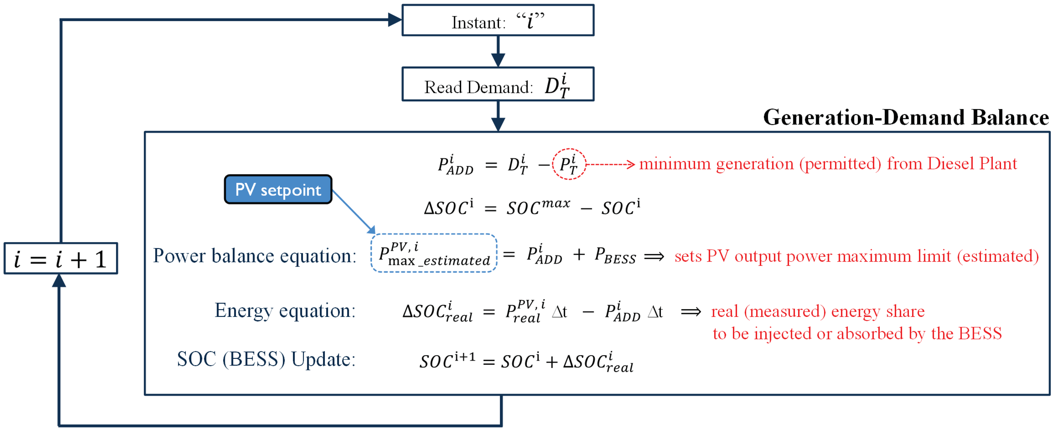
The discretized real-time ASC-
Grid off-grid operation for the base case is illustrated in
Figure 5. The simulation considers power balance and energy equations with the recurrent update of the batteries SOC. A one-second discretization was chosen.
The power balance equation allows the estimation of the PV injection setpoint. On the other hand, the energy equation permits the SOC update at each instant “i”, assuming that BESS has a charging/discharging rate of .
The DGs must be synchronized with the grid and settled in their minimum permissible power delivering point, totalizing
. Then, the demand
in each instant “
i” is subtracted from the total diesel generation, obtaining the difference needed to finish the power balance
. It will be provided by the PV plant and BESS, assuming a discharge rate such that BESS can supply 1 MW during one hour. Thus, the PV generation maximum setpoint is estimated by calculating the power injected by BESS plus the remaining demand that needs to be attended. The BESS equivalent power for each interval is calculated as follows:
where
,
is given in MWh,
in seconds, and
in MW. Note that BESS meets the balance in every instant. The PV maximum setpoint calculation is needed to avoid excess generation from the MG DERs, while the maximum green energy generation potential is explored within these limits.
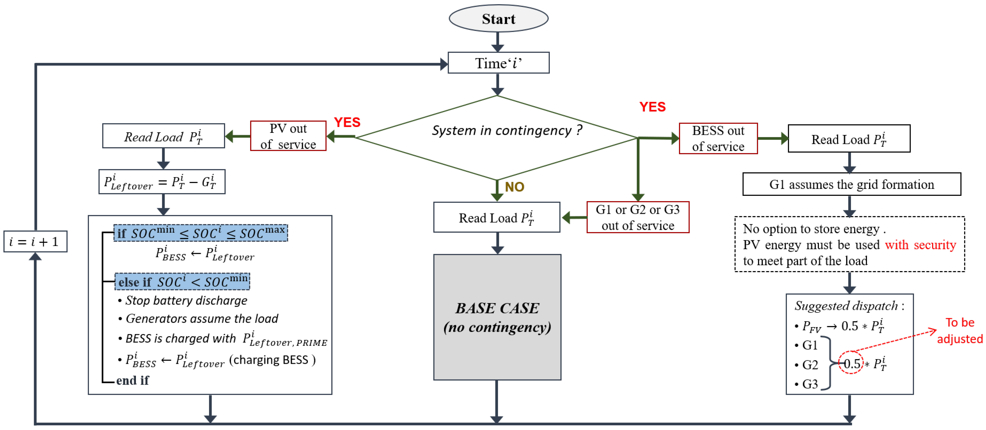
4.4. Off-Grid Operation Modeling including Contingencies
The DERs single contingencies are simulated through the algorithm sequence, aiming for the uninterrupted supply of ASC-Grid loads.
The algorithm of the MG operation with contingencies is depicted in
Figure 6. It includes
generation occurrences, following a corrective control strategy [
32], i.e., it is assumed that the remaining operational sources have time responses compatible with single generation contingencies, redistributing the respective load sharing setpoints without power supply interruption.
4.4.1. Outage of BESS
The outage of BESS is the most critical contingency because the smoothing capability of this device is lost. In this scenario, a diesel unit assumes the microgrid reference. Considering that we do not know a priori whether diesel generators can adequately compensate for PV variability, we are assuming to limit the share of PV generation to , as shown in the figure. However, this criterion can be adjusted in further studies. Since this is a critical microgrid, a conservative criterion will be well received.
4.4.2. Outage of PV Generator
As a consequence of the outage of the PV generator, the microgrid has only one type of generating source: diesel generators. Although it is not a critical contingency, it makes the operation dependent on fossil fuel. Assuming that the battery was charged with clean energy, it makes sense to prioritize the use of this stored energy being supplemented with diesel generation. If the absence of PV generation persists and the SOC reaches the minimum value allowed, the DGs must assume the entire load. In this scenario, BESS can be charged using the idle generators’ capacity if this is operationally and economically attractive (e.g., operating generators at a more efficient point or post-contingency scenario remaining for a long time).
4.4.3. Outage of One Diesel Generator at a Time
The outage of a DG unit is not critical and is already considered in the control of the generator set. Therefore, the remaining generators can share the unsupplied load. However, the dynamics of BESS are faster, and it should instantly restore balance. It is desirable that the remaining generators remain at their minimum limit and thus exploit PV energy more intensively. Note that this contingency scenario fits a base case where total diesel generation was only decreased. For this reason, for contingencies of diesel generators, the algorithm in
Figure 6 points to the “base case” block.
5. On-Grid Operation Modeling
As stated previously, in this operation mode, the ASC-Grid PCC switch is closed, and the MCMG is connected with the utility grid. As a result, energy management strategies are being implemented to reduce energy consumption costs and pollutant emissions. Here, the use of renewable DERs is a priority to achieve these goals.
On-Grid Operation Mathematical Modeling
The ASC-
Grid on-grid operation can be formulated as a multi-period optimization problem. The objective function is non-specific in operational costs and power supply options. The formulation is given by Equations (
11)–(
13).
The formulation allows variable energy costs during the optimization period, e.g., 24 h. The discretization time is defined, a priori, according to the desired precision. However, a very high discretization implies an additional computational cost. Depending on costs, the diesel option may be activated sometimes, but it will undoubtedly have a very low priority. The power supplied by the main grid closes the power balance. It can be positive (microgrid absorbing energy) or negative (microgrid injecting energy). The formulation includes the integer variable , which determines the current regime of BESS:
This also includes constraints (
3) and (
4).
where represents the power injected (negative values) or absorbed (positive values) by the microgrid at the PCC, and is the cost associated with energy from the grid.
6. Off-Grid Simulations
The following general conditions were considered for the off-grid simulations:
ASC demand: typical daily demand curve (15 min discretization interval);
Solar irradiation: Real data obtained from measurements taken on-site on a typical day (1 min discretization interval);
Islanding period: from 07:00 to 12:00 (5 h total, according to the mean duration of programmed islanding of the microgrid);
SOC estimation: coulombs counting (constant voltage);
BESS maximum SOC: 95% according to manufacturer recommendations;
DGs operation mode: Prime;
The minimum allowed power of DGs: 100 kW each.
DG’s consumption chart is shown in the
Table 3.
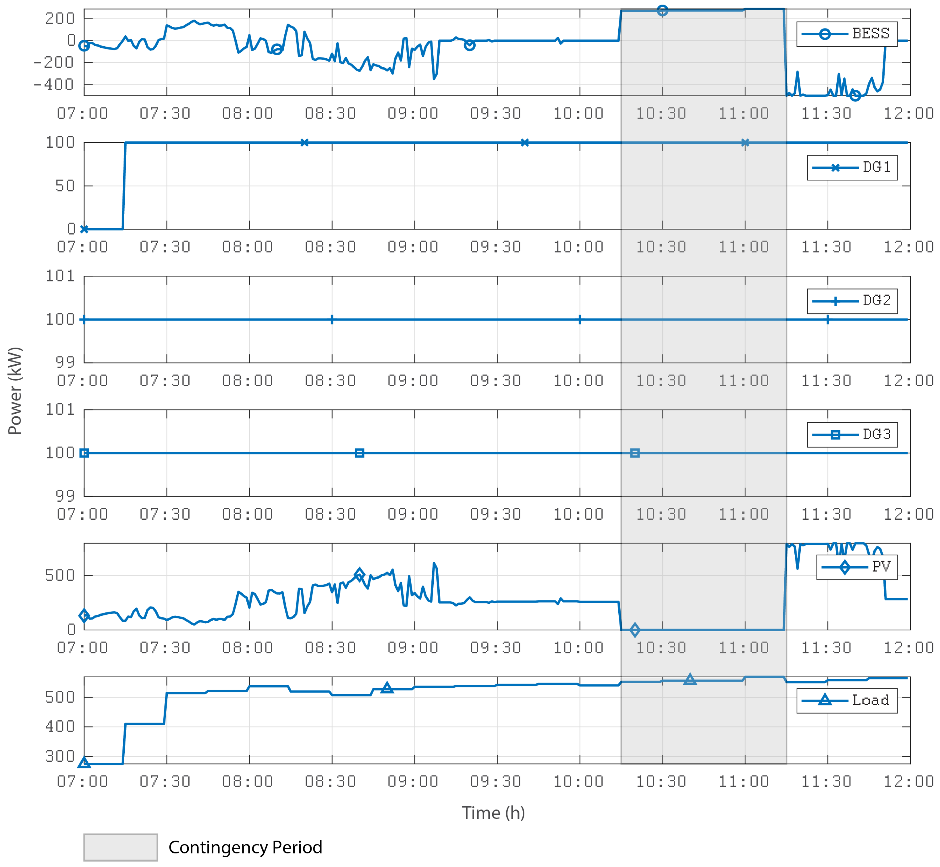
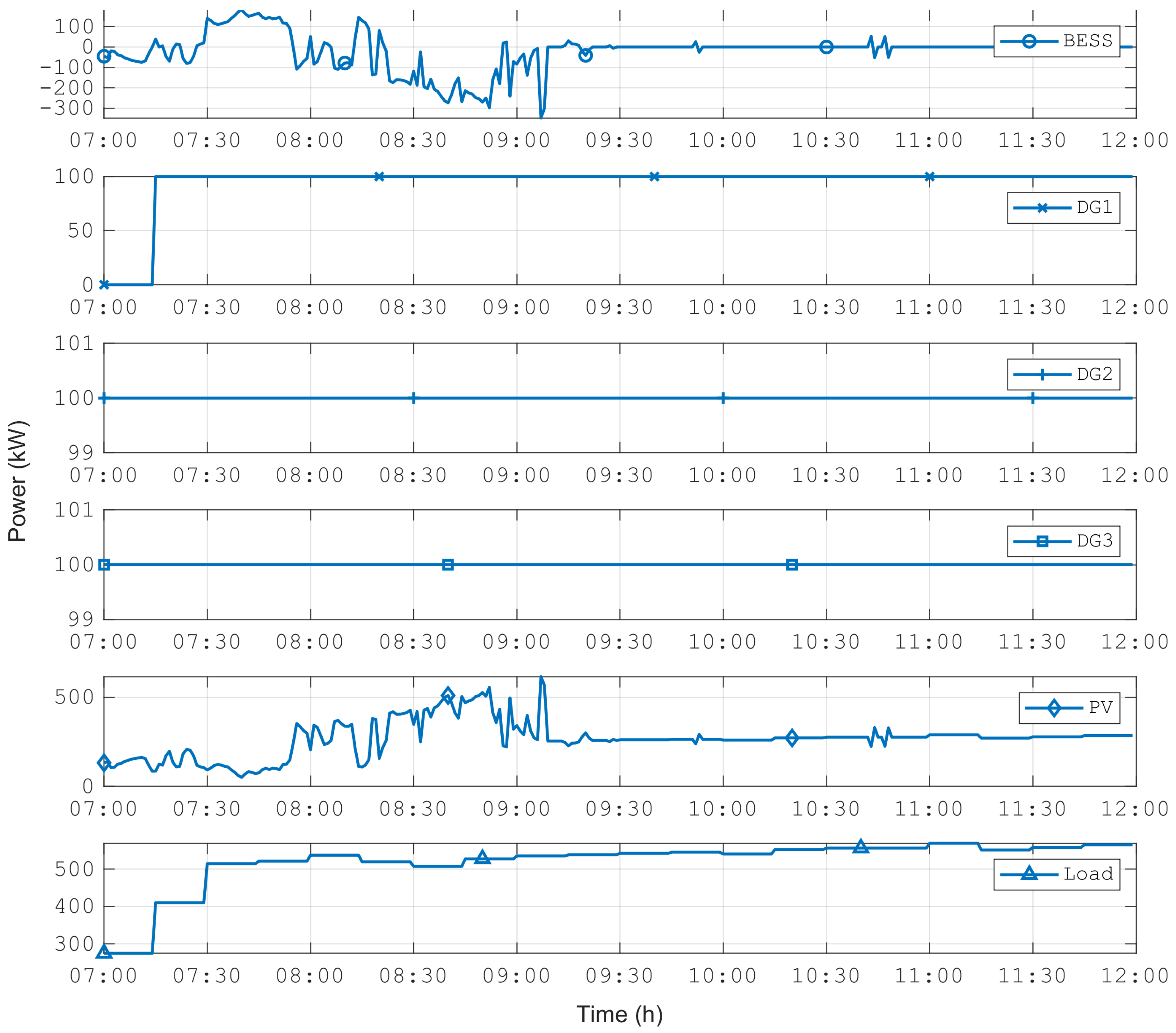
6.1. Base Case Simulation
All power sources, except the utility grid, are available in this scenario, and BESS assumes the role of grid-forming DER. The ASC-
Grid operation in this scenario is illustrated in
Figure 7 and
Figure 8. The DERs generation and the ASC load curves are shown in
Figure 7. BESS SOC and power injected or absorbed are depicted in
Figure 8 (positive values mean injected power), and details on DGs fuel consumption are shown in
Table 4. This case simulation was performed following the proposed modeling depicted in
Figure 5.
To fulfill the constraint of minimal power delivered by the DGs, Generator 1 is activated only after a significant change in the ASC load level, according to Equation (
3). Then, all DG units remain generating in baseload, injecting minimal power as recommended by the manufacturer.
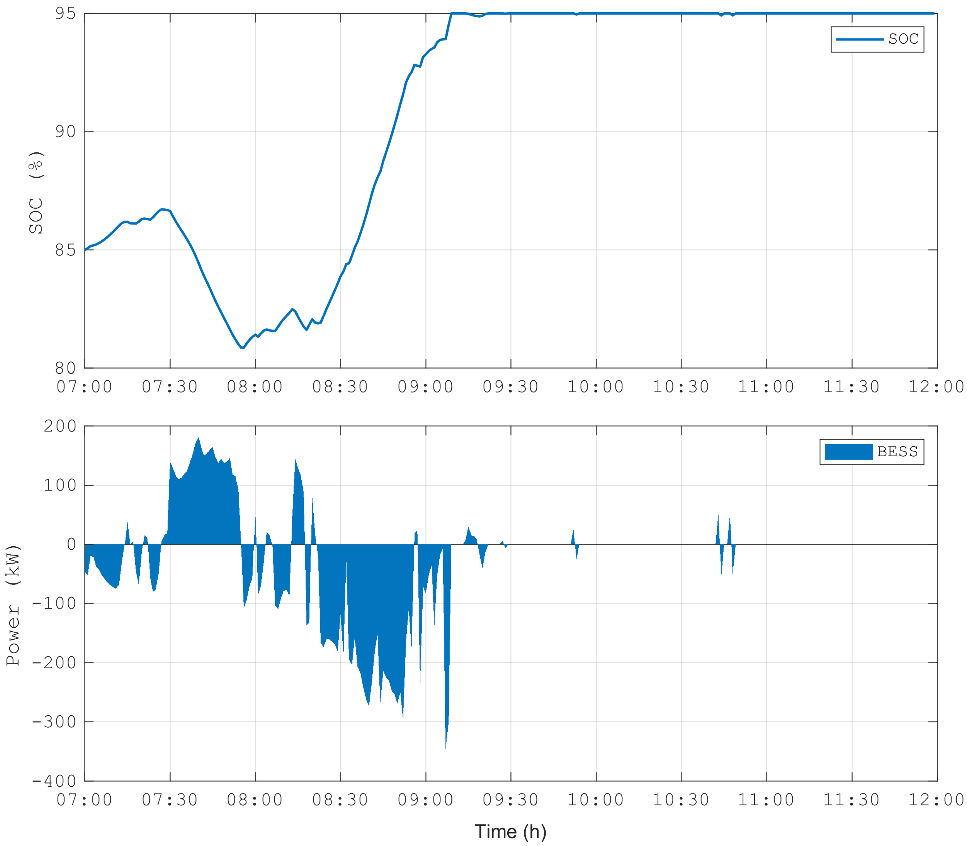
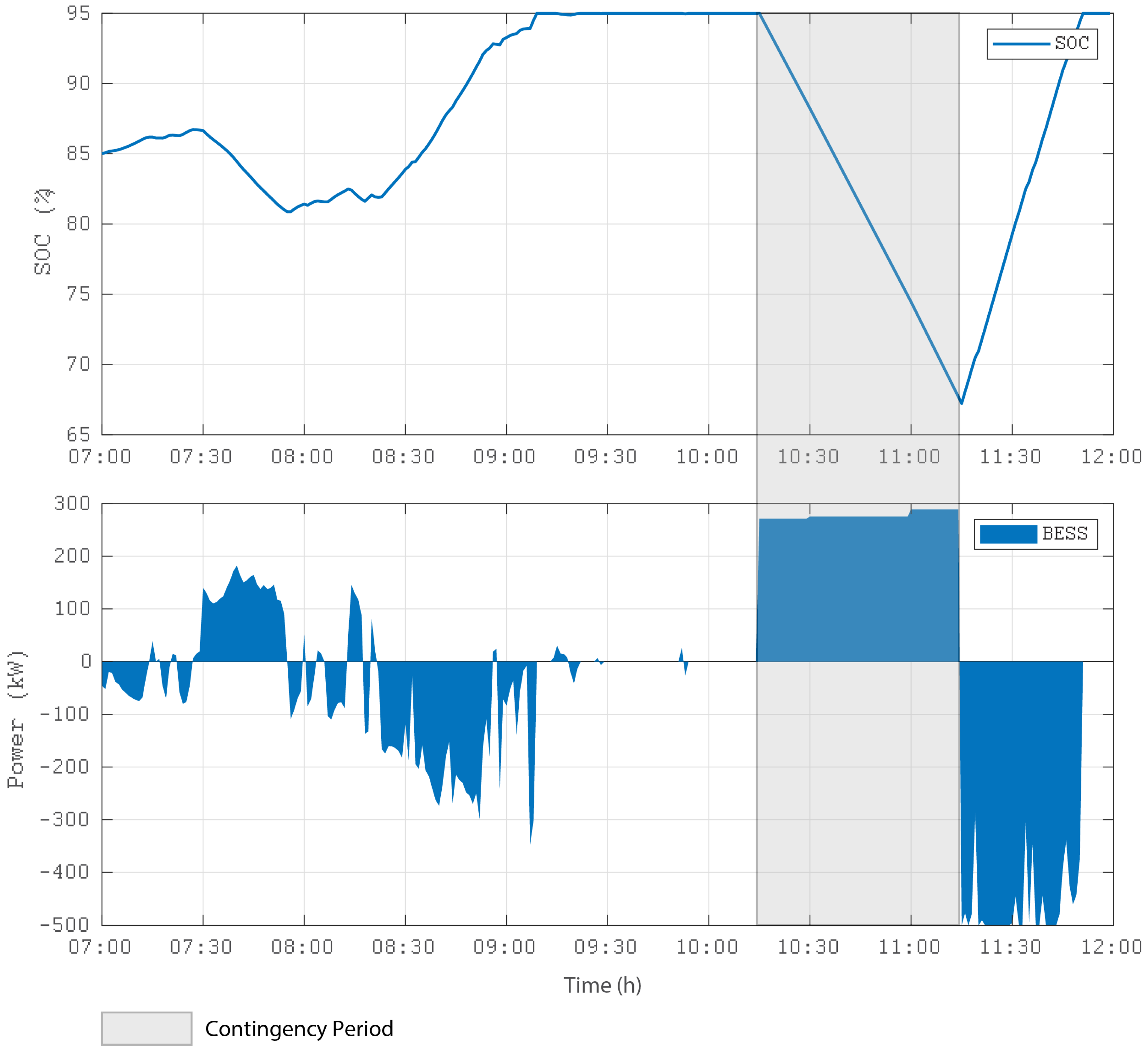
Over the simulation period, BESS remains at a high level of SOC, reducing the energy absorption margin. As a consequence, PV generation must be limited to keep power balance, as seen in
Figure 7, where after 9:30 a.m., the allowable PV generation remains approximately constant. Notice that from the operational security perspective, a high SOC level is more suitable for keeping system reliability and resilience to face contingencies in off-grid mode.
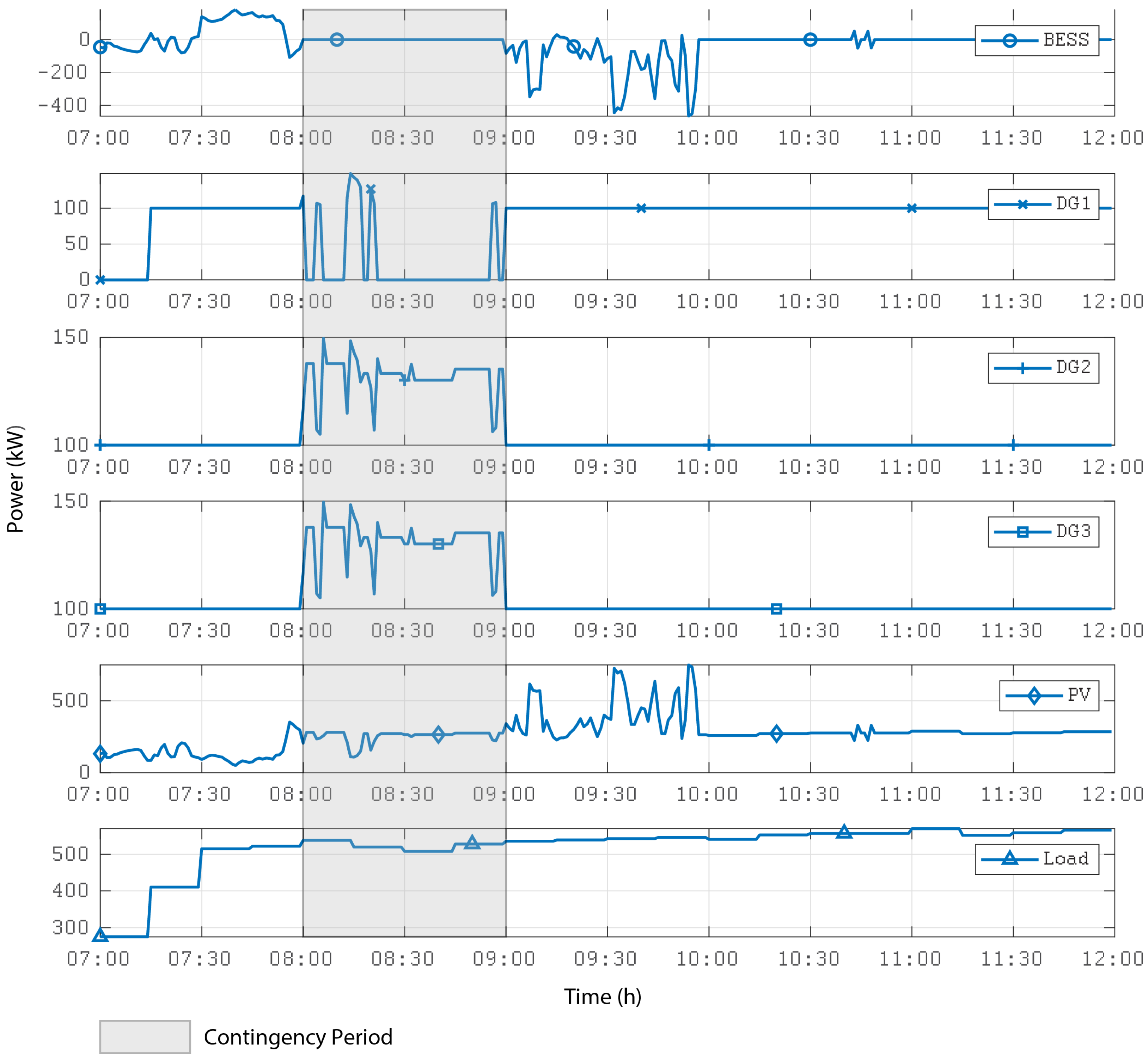
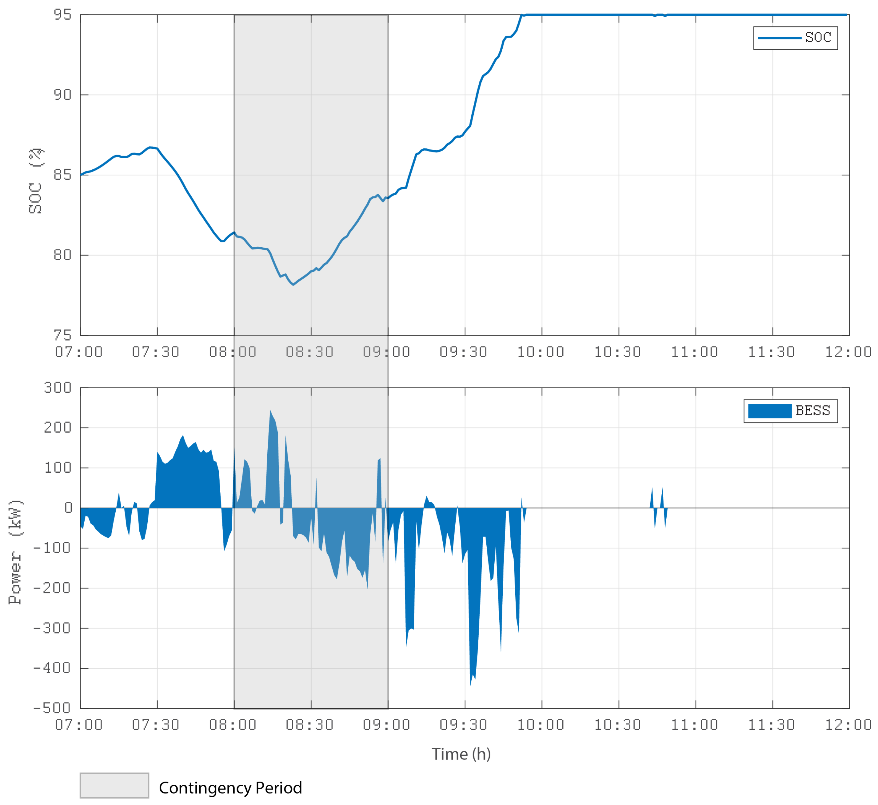
6.2. Contingency Simulation: BESS Outage
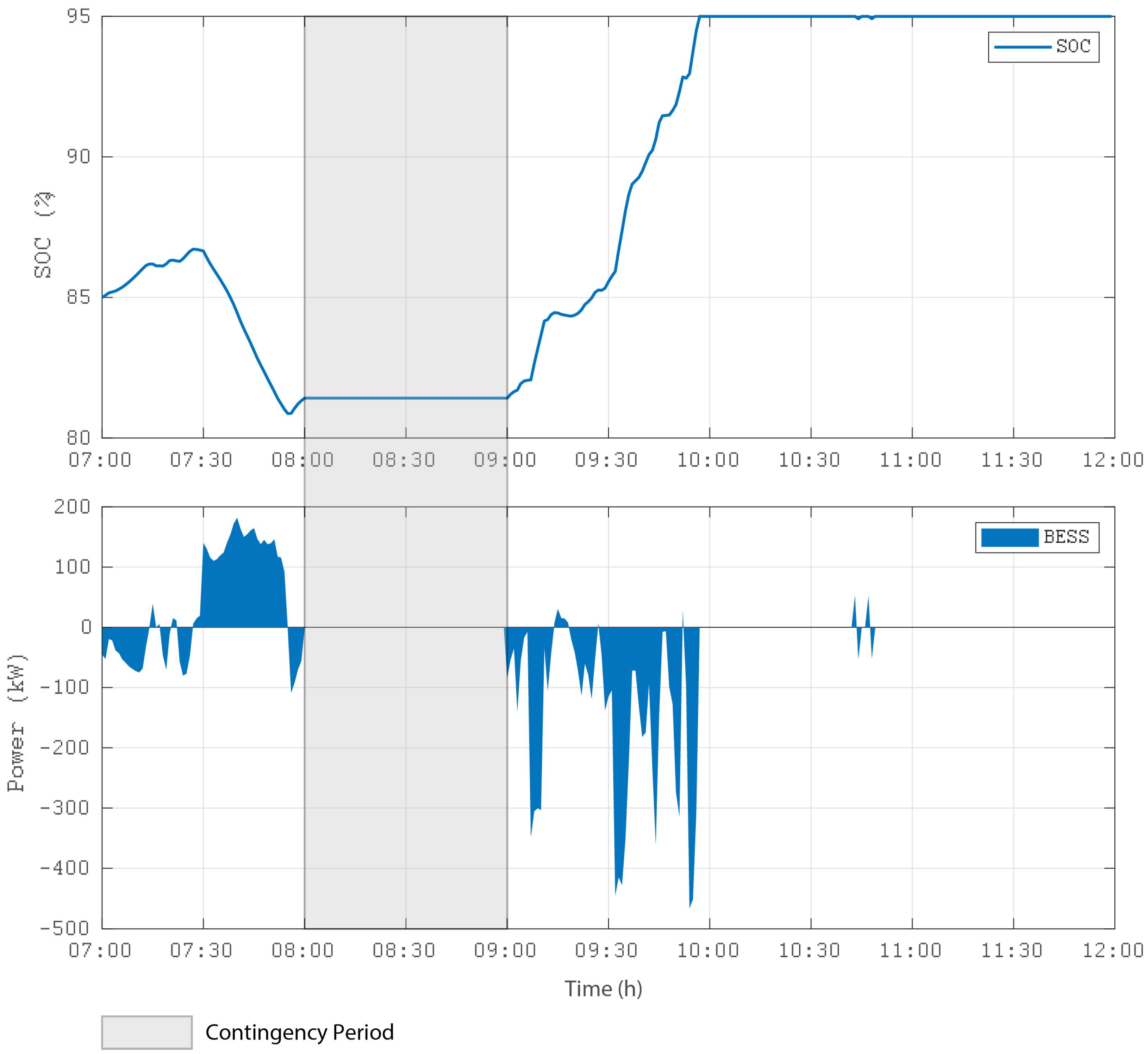
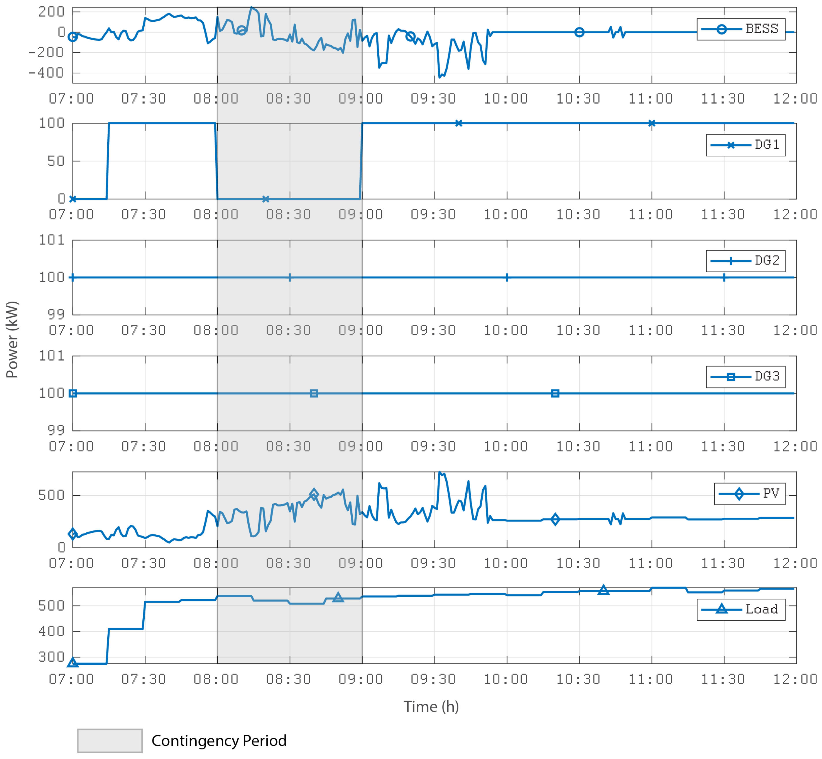
BESS is assumed to go out at 8:00 a.m., remaining unavailable until 09:00 a.m. In this case, the one DG takes on the role of grid former. The off-grid operation without BESS is one of the most critical conditions because BESS’s rapid response to disturbances is no longer available, and DGs have a slower dynamic. To alleviate this condition and provide an adequate safety margin, a conservative criterion has been applied by limiting the PV generation. The idea is to provide a reasonable margin of controllability to the generators, so that they can adequately absorb load fluctuations. For example, PV generation can be adjusted to provide a maximum of 50% of demand. Thus, DGs complement the remaining demand (see
Figure 9 and
Figure 10). This criterion can be better adjusted depending on the dynamics observed in the real future operation of the microgrid. The total and specific fuel consumption of the DG units for this scenario is shown in
Table 5.
6.3. Contingency Simulation: Single DG Outage
In this scenario, Generator 1 goes out of service between 8:00 and 9:00 a.m. The power of 100 KW that was supplied by this unit is now supplied by BESS. With the reduction of the participation of the DGs, the PV generator will be able to increase participation if there is availability. The details of the simulation of this scenario are presented in
Figure 11 and
Figure 12. The total and specific fuel consumption of the DG units for this scenario is shown in
Table 6.
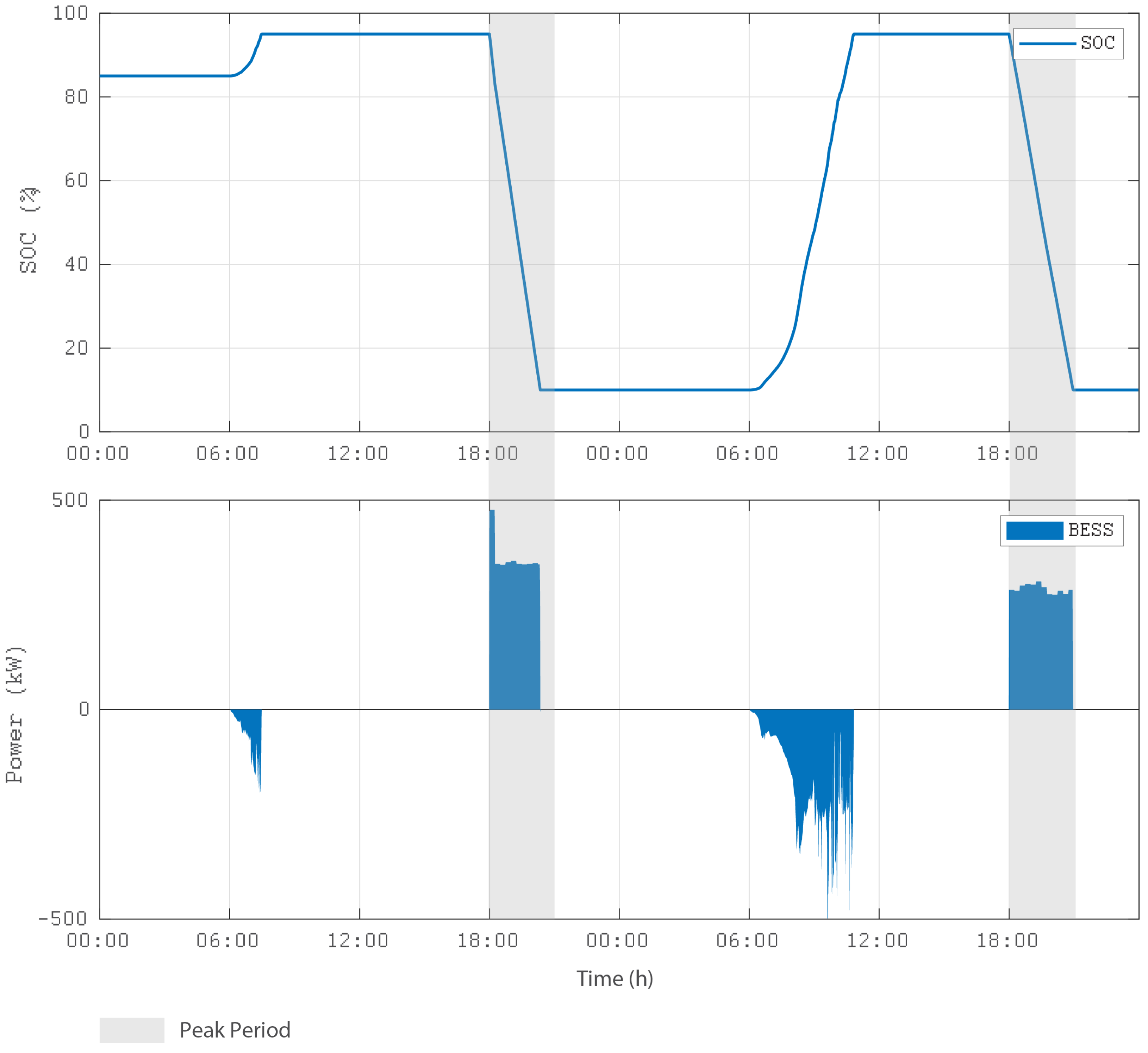
6.4. Contingency Simulation: PV Source Outage
In this example of a contingency scenario (PV outage), it is assumed that the PV plant goes out of operation at 10:15 h, remaining in this condition for one hour, as shown in
Figure 13.
The power supplied by PV is replaced by BESS, while diesel generators remain at their minimum generation limit. In this post-contingency scenario, all operational limits are satisfied.
After the contingency period, the PV array has enough generation to quickly recover the BESS state of charge, which will remain in this condition until the end of the day. The behavior of the state of charge and power of BESS is shown in
Figure 14. It is noted that, as the state of charge remained above its minimum value, additional diesel generation did not need to be used to charge BESS, keeping the generators at their minimum level, as shown in
Figure 13. The total and specific fuel consumption of the DG units for this scenario is shown in
Table 7.
7. On-Grid Simulation
The following general conditions were considered for on-grid simulation:
ASC demand: typical daily demand curve (15 min discretization interval);
Solar irradiation: Real data obtained from measurements taken on-site on typical days (1 min discretization interval);
Simulation period: two days;
SOC estimation: coulombs counting (constant voltage);
BESS maximum SOC: 95% (according to manufacturer recommendations);
Peak period: from 18:00 h to 20:59 h.
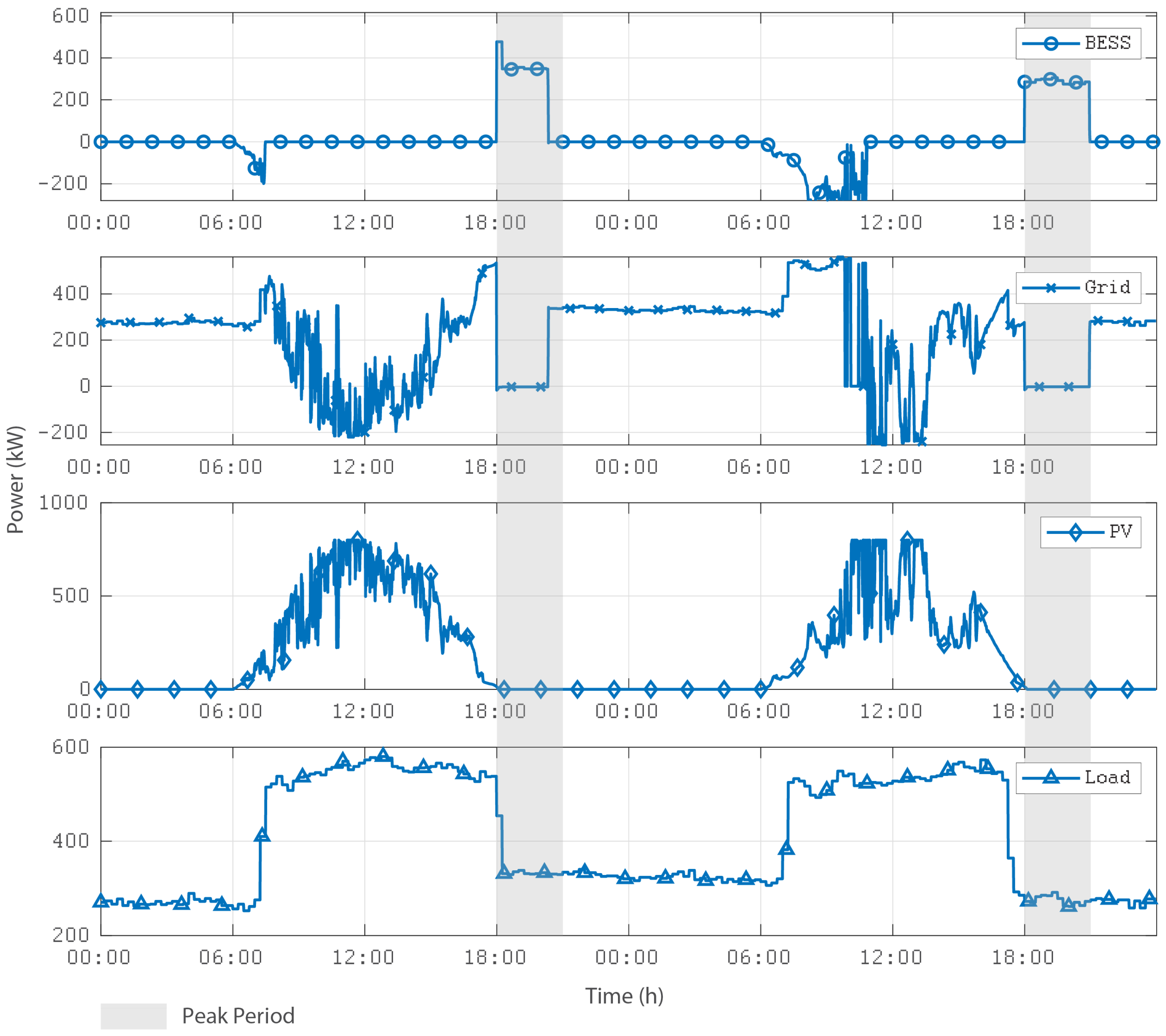
Figure 15 and
Figure 16 show details of the microgrid operation in the on-grid scenario: the two-day simulation is sufficient to demonstrate the microgrid operation during peak and off-peak periods. For demonstration purposes, it was assumed in this simulation that initially, BESS has an intermediate SOC value (in this case, 85%). During the early hours of the day, the microgrid is served exclusively by the grid before sunrise. Since it is an off-peak period, grid power is cheaper.
As shown in
Figure 15, BESS is charged by the PV source as long as the PV generation grows. After BESS reaches its maximum SOC (in this case, the maximum SOC is assumed to be equal to 95%), PV generation becomes the priority source for meeting demand, with the grid only being used for matching the power balance, absorbing or injecting power, according to fluctuations in PV generation. During the peak of PV generation, it is observed that this source can meet almost all the demand and export energy to the external grid. This condition allows the maximum exploitation of the renewable source during the on-grid operation. Since this mode of operation is the most common in the microgrid, intensive exploitation of the renewable source becomes evident.
Since the grid energy becomes more expensive during the peak period (from 18:00 h to 20:59 h), BESS should be used as a priority source to meet the demand. It is noted that BESS can meet almost all the demand during the peak period, reducing the need to buy expensive energy from the external grid. After the peak period, the grid becomes the priority source to meet demand, and BESS must be recharged primarily by the PV source the next day.
This energy arbitrage regime reduces energy purchase costs from the external grid and provides the intensive use of clean energy.
Table 8 summarizes an energy analysis for the simulated period, comparing the cases with and without the ASC-
Grid, and considering the peak and off-peak periods. As seen in the table, the microgrid operation reduces the energy imported from the grid from 17.53 MWh to 10.77 MWh, that is, a reduction of 39%; while for the peak period, this reduction is even more significant: from 1.85 MWh to 0.23 MWh, that is, a reduction of 88%. The microgrid’s operation allows a drastic reduction of energy imported from the grid, mainly in the peak period, when the energy tariff is more expensive (
$3,111,618/kWh). Furthermore, the operation of the microgrid allows part of the generated energy to be exported to the grid during the off-peak period (0.8 MWh). Considering the actual tariffs, the operation of the ASC-
Grid allows a reduction in energy costs from
$11,584.9 to
$4030.17, that is, a reduction of 65%. However, it is worth mentioning that this is an analysis based on the period of two typical simulated days, and it is also important to note that general charges are not considered. Despite this, this preliminary analysis indicates that the ASC-
Grid can provide significant financial benefits.
8. Discussion
For the ASC off-grid operation in the base case (i.e., without contingencies), as can be seen in
Figure 7 and
Figure 8, BESS is initially charged by DGs. Once the ASC load is in a lower level, these generators are operating to ensure an uninterrupted power supply in moments without PV generation. Later, when there is an increase in solar irradiation, the PV plant can help charge BESS and assume a significant load share. This condition avoids DG units from operating above their minimum allowed power setpoint, and, as a consequence, their fuel consumption is as minimal as possible. After BESS is fully charged, PV generating setpoint (see
Figure 4) has to be reduced once there is no utility grid to absorb the excess power produced by the PV plant. Note also from
Figure 7 and
Figure 8 that PV generation variations are immediately absorbed by BESS, without prejudice to ASC loads power supply. The base case simulations demonstrate that the ASC-
Grid can maintain ASC operational security during a launch campaign with minimum pollutant emission.
In the case of the off-grid operation with one hour of BESS outage (
Figure 9 and
Figure 10), the DG units are the main responsible DERs that support ASC loads, instead of their slow response, because of the inherent variability of PV generation. However, even with a lower PV injection setpoint, the power generated by this source reduces the load step-up required by DG units. Besides, the PV generation is such that one of the DG units must be turned off to preserve the ASC-
Grid generation-demand balance. Once BESS is restored, the PV setpoint is elevated to charge it to ensure power supply redundancy for the MCMG, which is necessary to reinforce resilience and operational security.
The case with a single DG outage in off-grid operation (
Figure 11 and
Figure 12) is very similar to the base case, once the PV source is capable of assuming the load share of the lost DG and also charging BESS. The only particularities of this contingency case are the lower fuel consumption and the reduced power supply redundancy. The last one may impact ASC-
Grid capability to support other contingencies.
For the case with only a PV source outage in off-grid operation (
Figure 13 and
Figure 14), BESS is responsible for absorbing PV load share due to the fast dynamics of this storage system and no change of power required is viewed from DG’s side. For example, if one contingency of this type persists until BESS measured SOC is near to the minimum permitted value (10% according to the manufacturer of the ASC-
Grid storage solution), the MG energy management system changes the setpoint power required for DG units in order to supply ASC loads in proper time, avoiding interruptions.
Furthermore, observe from
Table 4,
Table 5,
Table 6 and
Table 7 that the fuel consumption of DG units is kept as low as possible for all cases considered in off-grid (with and without
contingencies). Thus, it is expected that the ASC-
Grid, when implemented and fully operational, will be capable of keeping ASC operational security and power supply resilience to
contingencies with reduced pollution due to the necessary use of non-renewable dispatchable sources to attend to ASC off-grid operation demands. On the other hand, the results for on-grid operation (
Figure 15 and
Figure 16) evidence the benefits of ASC-
Grid renewable DERs presence in periods without launch campaigns. The economic and environmental demands required for this scenario are fulfilled by the joint action of the PV plant and BESS.
9. Conclusions
This article reported the conception and design of a mission-critical microgrid, namely, the ASC-Grid, which is currently being implemented to attend to the specific demands of the Alcântara Space Center, a government military facility in Brazil. The main goal for this microgrid is to guarantee power supply reliability and operational security, especially during launch campaigns, when operation disconnected from the local utility grid is mandatory. This critical and specific scenario is more complex for the ASC-Grid to attend to, and, therefore, it was designed to support generation contingencies without supply interruption. Other benefits also reached as a consequence of this microgrid implementation are reduced electricity purchase costs and pollutant emissions and improved power quality and reliability of Alcântara Space Center’s internal grid. In order to attend to the most critical demands of the application, on-grid and off-grid operation scenarios were modeled as discretized optimization problems that include algorithms to manage generation-demand balance, generation setpoints of the available sources, and also to deal with possible contingencies that may happen. In addition, the proposed modeling considers the existence of physical monitoring, control, energy management, and communication systems, which will be part of ASC-Grid infrastructure once it is implemented and fully operational. Then, to verify the capability of the proposed formulation to attend to the application demands, a power study was carried out considering mainly ASC-Grid off-grid scenarios with and without contingencies, and also an on-grid operation where strategies to reduce energy bills were tested. The results of off-grid simulations show that the ASC-Grid will be able to guarantee power supply resilience and operational security to the Alcântara Space Center, with minimal use of pollutants. However, dispatchable sources, during launch campaigns, even in the face of contingencies occurrence are necessary. On the other hand, on-grid simulation evidences the ASC-Grid’s capability of using onsite renewable distributed resources to support the Alcântara Space Center’s loads, inject excess power back into the utility grid, and use stored green energy to reduce external energy purchases in peak demand periods. The obtained results also show that the proposed microgrid can satisfactorily balance requirements such as the economy, emission reduction, and high reliability, in order to meet the rigid and critical demands of a space launch center.
Author Contributions
Conceptualization, C.A.S.C.B.; Investigation, J.G.d.M.; Methodology, P.B.L.N.; Project administration, O.R.S., L.A.d.S.R., M.F.A.J., L.d.P.A.P. and R.M.C.; Resources, C.A.S.C.B., J.G.d.M., C.B.M.O., M.F.A.J., L.d.P.A.P. and R.M.C.; Supervision, C.B.M.O., L.A.d.S.R. and A.C.O.; Visualization, A.C.O.; Writing—review & editing, C.A.S.C.B., F.P.M., H.A.O., P.B.L.N. and O.R.S. All authors have read and agreed to the published version of the manuscript.
Funding
The authors are grateful for the financial support of Equatorial Energia, Conselho Nacional de Desenvolvimento Científico e Tecnológico—CNPq, Fundação de Amparo à Pesquisa Estado do Maranhão—FAPEMA and Coordenação de Aperfeiçoamento de Pessoal de Nível Superior—Brazil (CAPES)—Finance Code 001.
Institutional Review Board Statement
Not applicable.
Informed Consent Statement
Not applicable.
Acknowledgments
The authors would like to acknowledge the support of Federal University of Maranhão in the development of this work.
Conflicts of Interest
The authors declare no conflict of interest.
References
- Vargas, A.; Saavedra, O.R.; Samper, M.E.; Rivera, S.; Rodriguez, R. Latin American Energy Markets: Investment Opportunities in Nonconventional Renewables. IEEE Power Energy Mag. 2016, 14, 38–47. [Google Scholar] [CrossRef]
- Ribeiro, L.; Saavedra, O.; Lima, S.; de Matos, J.; Bonan, G. Making isolated renewable energy systems more reliable. Renew. Energy 2012, 45, 221–231. [Google Scholar] [CrossRef]
- Ton, D.T.; Smith, M.A. The U.S. Department of Energy’s Microgrid Initiative. Electr. J. 2012, 25, 84–94. [Google Scholar] [CrossRef]
- Hatziargyriou, N. Microgrids: Architectures and Control; John Wiley & Sons: Hoboken, NJ, USA, 2014. [Google Scholar] [CrossRef]
- Hadjidemetriou, L.; Zacharia, L.; Kyriakides, E.; Azzopardi, B.; Azzopardi, S.; Mikalauskiene, R.; Al-Agtash, S.; Al-hashem, M.; Tsolakis, A.; Ioannidis, D.; et al. Design factors for developing a university campus microgrid. In Proceedings of the 2018 IEEE International Energy Conference (ENERGYCON), Limassol, Cyprus, 3–7 June 2018; pp. 1–6. [Google Scholar] [CrossRef] [Green Version]
- Cheng, Z.; Duan, J.; Chow, M.Y. To Centralize or to Distribute: That Is the Question: A Comparison of Advanced Microgrid Management Systems. IEEE Ind. Electron. Mag. 2018, 12, 6–24. [Google Scholar] [CrossRef]
- Muqeet, H.A.; Munir, H.M.; Javed, H.; Shahzad, M.; Jamil, M.; Guerrero, J.M. An Energy Management System of Campus Microgrids: State-of-the-Art and Future Challenges. Energies 2021, 14, 6525. [Google Scholar] [CrossRef]
- Mengelkamp, E.; Gärttner, J.; Rock, K.; Kessler, S.; Orsini, L.; Weinhardt, C. Designing microgrid energy markets: A case study: The Brooklyn Microgrid. Appl. Energy 2018, 210, 870–880. [Google Scholar] [CrossRef]
- Hirsch, A.; Parag, Y.; Guerrero, J. Microgrids: A Review of Technologies, Key Drivers, and Outstanding Issues. Renew. Sustain. Energy Rev. 2018, 90, 402–411. [Google Scholar] [CrossRef]
- Cosme, D.L.S.; Saavedra, O.R.; de Souza Ribeiro, L.A.; de Matos, J.G.; Oliveira, H.A.; de Lima, S.L.; de Paula Assunção Pinheiro, L. Performance Analysis and Impact of the Improvements added in Ten-Years of Operation of Microgrid of Lençóis Island. In Proceedings of the 45th Annual Conference of the IEEE Industrial Electronics Society, Lisbon, Portugal, 14–17 October 2019; pp. 2458–2463. [Google Scholar] [CrossRef]
- Anderson, W.W. Smart Power Infrastructure Demonstration for Energy Reliability and Security (SPIDERS) Final Report; Naval Facilities Engineering Command: Pearl Harbor, HI, USA, 2015. [Google Scholar]
- Cybersecurity and Infrastructure Security Agency CISA—Critical Infrastructure Sectors. Available online: https://www.cisa.gov/critical-infrastructure-sectors (accessed on 31 March 2022).
- Presidency of the Federative Republic of Brazil. Decree 10569 (9 December 2020)—National Strategy for Critical Infrastructure Security. Available online: https://www.in.gov.br/en/web/dou/-/decreto-n-10.569-de-9-de-dezembro-de-2020-293251357 (accessed on 11 April 2022).
- Peterson, C.J.; Van Bossuyt, D.L.; Giachetti, R.E.; Oriti, G. Analyzing Mission Impact of Military Installations Microgrid for Resilience. Systems 2021, 9, 69. [Google Scholar] [CrossRef]
- Giachetti, R.; Peterson, C.; Van Bossuyt, D.; Parker, G. Systems Engineering Issues in Microgrids for Military Installations. INCOSE Int. Symp. 2020, 30, 731–746. [Google Scholar] [CrossRef]
- Gutierrez-Rojas, D.; Nardelli, P.H.J.; Mendes, G.; Popovski, P. Review of the State of the Art on Adaptive Protection for Microgrids Based on Communications. IEEE Trans. Ind. Inform. 2021, 17, 1539–1552. [Google Scholar] [CrossRef]
- Khalili, T.; Bidram, A. Distributed control approaches for microgrids. In Microgrids; Springer: Cham, Switzerland, 2021; pp. 275–288. [Google Scholar]
- Espín-Sarzosa, D.; Palma-Behnke, R.; Núñez-Mata, O. Energy Management Systems for Microgrids: Main Existing Trends in Centralized Control Architectures. Energies 2020, 13, 547. [Google Scholar] [CrossRef] [Green Version]
- S&C Electric Company—Case Study Microgrid: Mission-Critical Military Base Enhances Power Resiliency with S&C’s Microgrid Control System. Available online: https://www.sandc.com/globalassets/sac-electric/documents/sharepoint/documents—all-documents/case-study-2000-1002.pdf?dt=637843708562560430 (accessed on 31 March 2022).
- Military Daily News. Available online: http://www.military.com/daily-news/2018/09/10/us-military-braces-typhoon-mangkhut-bears-down-guam.html (accessed on 31 March 2022).
- Smith, S. Learn More about the Marine Corps Base-29 Palms, CA. Available online: https://www.liveabout.com/installation-overview-mcagcc-twentynine-palms-california-3357090 (accessed on 8 March 2022).
- A Resilient Microgrid Solution Designed to Maximize the Solar Arrays, Enhance the Efficiency of the Existing Generator System and Provide Continuous Operation with Minimal Maintenance and Oversight. Available online: https://www.saftbatteries.com/resilient-power-solutions-microgrids (accessed on 31 March 2022).
- Military Microgrid at Parris Island Promises to Ensure Reliable Energy. Available online: https://microgridknowledge.com/military-microgrid-parris-island/ (accessed on 8 March 2022).
- Nelson, J.; Johnson, N.; Fahy, K.; Hansen, T. Statistical development of microgrid resilience during islanding operations. Appl. Energy 2020, 279, 115724. [Google Scholar] [CrossRef]
- Rickerson, W.; Zitelman, K.J. Valuing Resilience for Microgrids: Challenges, Innovative Approaches, and State Needs; National Association of Regulatory Utility Commissioners (NARUC), National Association of State Energy Officals (NASEO): Washington, DC, USA, 2022; Volume 1. [Google Scholar]
- Chamana, M.; Schmitt, K.; Bhatta, R.; Osman, I.; Liyanage, S.; Murshed, M.; Bayne, S.; MacFie, J. Hierarchical Operation of Flexible Building Microgrids for Distributed Critical Loads Resiliency. In Proceedings of the 2021 Resilience Week (RWS), Salt Lake City, UT, USA, 18–21 October 2021; pp. 1–9. [Google Scholar] [CrossRef]
- Mallery, J.; Van Bossuyt, D.L.; Pollman, A. Defense Installation Energy Resilience for Changing Operational Requirements. Designs 2022, 6, 28. [Google Scholar] [CrossRef]
- Hamanaka, R.; Obara, S. Study on the fuel consumption in the Antarctica Showa Base microgrid. In Proceedings of the 2016 IEEE PES Asia-Pacific Power and Energy Engineering Conference (APPEEC), Xi’an, China, 25–28 October 2016; pp. 1599–1603. [Google Scholar] [CrossRef]
- ABB. Onboard Microgrid Overcome Your Power Distribution Challenges. Available online: https://new.abb.com/marine/systems-and-solutions/electric-solutions/onboard-microgrid (accessed on 11 April 2022).
- IEEE Std 2030.7-2017; IEEE Standard for the Specification of Microgrid Controllers. IEEE: Piscataway, NJ, USA, 2018; pp. 1–43. [CrossRef]
- IEEE Std 1547-2018 (Revis. IEEE Std 1547-2003); IEEE Standard for Interconnection and Interoperability of Distributed Energy Resources with Associated Electric Power Systems Interfaces. IEEE: Piscataway, NJ, USA, 2018; pp. 1–138. [CrossRef]
- Saavedra, O.R. Relaxed approach for the parallel solution of security-constrained dispatch with post-contingency rescheduling. IEE Proc. Gener. Transm. Distrib. 2013, 150, 291–296. [Google Scholar] [CrossRef]
Figure 1.
Illustration of the topology proposed for the ASC-Grid.
Figure 1.
Illustration of the topology proposed for the ASC-Grid.
Figure 2.
Characteristics and benefits of ASC-Grid operation scenarios.
Figure 2.
Characteristics and benefits of ASC-Grid operation scenarios.
Figure 3.
ASC-Grid transition modes.
Figure 3.
ASC-Grid transition modes.
Figure 4.
Definition of the PV maximum injection setpoint compared to its total capacity.
Figure 4.
Definition of the PV maximum injection setpoint compared to its total capacity.
Figure 5.
Discretized modeling of the ASC-Grid real time operation.
Figure 5.
Discretized modeling of the ASC-Grid real time operation.
Figure 6.
Discretized modeling of the ASC-Grid real time operation in off-grid mode—case with contingencies.
Figure 6.
Discretized modeling of the ASC-Grid real time operation in off-grid mode—case with contingencies.
Figure 7.
DERs generation and ASC load curves for off-grid operation (base case).
Figure 7.
DERs generation and ASC load curves for off-grid operation (base case).
Figure 8.
SOC variation and BESS injected/absorbed power for off-grid operation (base case).
Figure 8.
SOC variation and BESS injected/absorbed power for off-grid operation (base case).
Figure 9.
DERs generation and ASC load curves for off-grid operation (case with BESS outage and PV plant limited to 50% of ASC demand).
Figure 9.
DERs generation and ASC load curves for off-grid operation (case with BESS outage and PV plant limited to 50% of ASC demand).
Figure 10.
SOC variation and BESS injected/absorbed power for off-grid operation (case with BESS outage and PV plant limited to 50% of ASC demand).
Figure 10.
SOC variation and BESS injected/absorbed power for off-grid operation (case with BESS outage and PV plant limited to 50% of ASC demand).
Figure 11.
DERs generation and ASC load curves for off-grid operation—case with a single DG unit outage.
Figure 11.
DERs generation and ASC load curves for off-grid operation—case with a single DG unit outage.
Figure 12.
SOC variation and BESS injected/absorbed power for off-grid operation—case with a single DG unit outage.
Figure 12.
SOC variation and BESS injected/absorbed power for off-grid operation—case with a single DG unit outage.
Figure 13.
DERs generation and ASC load curves for off-grid operation—case with PV source outage.
Figure 13.
DERs generation and ASC load curves for off-grid operation—case with PV source outage.
Figure 14.
SOC variation and power and BESS injected/absorbed power for off-grid operation (case with PV source outage).
Figure 14.
SOC variation and power and BESS injected/absorbed power for off-grid operation (case with PV source outage).
Figure 15.
DERs generation and ASC load curves for on-grid operation.
Figure 15.
DERs generation and ASC load curves for on-grid operation.
Figure 16.
SOC variation and BESS injected/absorbed power for on-grid operation.
Figure 16.
SOC variation and BESS injected/absorbed power for on-grid operation.
Table 1.
Cases of microgrids for critical infrastructure applications.
Table 1.
Cases of microgrids for critical infrastructure applications.
| Microgrid | Power Supply | Functionalities | Loads | Remarks |
|---|
| | Infrastructure | and/or Goals | Supplied | |
|---|
| Fort Belvoir mission critical microgrid [19] | • 3 fixed natural gas generators (905 kW)
• 4 mobile diesel generators (400 kW)
• PV plant (16 kW) | • Reduce operational
• Ensure resilience during islanding events | Thirteen buildings of Fort Belvoir | • Distributed control system that provides automated and smart decision making, with incorporated cybersecurity
• Islanding test realized during implementation demonstrated that all operational goals were accomplished |
| Parris Island isolated microgrid [23] | • PV Plant (6.7 MW)
• CHP plant (5 MW)
• BESS (8 MWh)
• Diesel generators (3.5 MW) | • Provide reliable and safe energy to customers
• Reduce operational costs
• Dampen market price variation of commodities
• Power supply resilience | Local buildings and installations | • Power dispatch is coordinated by an energy management system that applies load selectivity |
| Japan’s Showa Research Base isolated microgrid in Antarctica [28] | • 3 Diesel Generators (100 kW)
• PV Plant (100 kW)
• 5 wind turbines (20 kW)
• Solid oxide fuel cell (100 kW) | • Continuous energy supply for all bases
• Uninterrupted operation with reduced fuel consumption | All Showa Base installations | • Presence of fuel cell lowered diesel use by 16.5% in the winter
• Grid frequency variations controlled by proper setponit of PV and wind generation |
| ABB onboard [29] | Multiple hybrid power sources:
• Diesel and gas generators
• BESS
• Fuel cells | • Power supply in maritime environment applications
• Ships propulsion applications | All loads of a marine vessel | • Modules of hybrid energy system are configured as inverters, supply units or DC/DC converters, depending on available sources |
| Fort Carson military microgrid [11] | • PV plant (2 MW)
• 3 diesel generators (3 MW)
• BESS (4.5 MW/8.5 MWh) | • Guarantee power supply even in the case of utility grid loss
• Siignificantly reduce fuel consumption (also with the use of electric vehicles) | Seven buildings of Fort Carson Base | • In operation since 2014
• Electric vehicles also used to serve the microgrid as storage units |
Table 2.
Estimated earnings with the microgrid.
Table 2.
Estimated earnings with the microgrid.
| | Current Scenario | Scenario with ASC-Grid |
|---|
| | On-Grid | Off-Grid | On-Grid | Off-Grid |
|---|
| Annual Expenses with Diesel (US$) | 0 | 174,890.98 | 0 | 113,051.07 |
| Annual Purchased Energy (US$) | 425,533.89 | 0 | 126,230.07 | 0 |
| Annual Emissions (kg of CO2) | 411,289.20 | 265,861.44 |
| Annual Total Cost (US$) | 600,424.88 | 239,281.14 |
Table 3.
DG units fuel consumption chart.
Table 3.
DG units fuel consumption chart.
| | Fuel Consumption (L/h) |
|---|
| 1/4 load | 24 |
| 1/2 load | 48 |
| 3/4 load | 66 |
| Full load | 80 |
Table 4.
DG units total and specific fuel consumption for off-grid operation (base case).
Table 4.
DG units total and specific fuel consumption for off-grid operation (base case).
| | Total Fuel Consumption (L) | Specific Fuel Consumption (L/kWh) |
|---|
| DG1 | 168.8 | 0.3556 |
| DG2 | 177.7 | 0.3556 |
| DG3 | 177.7 | 0.3556 |
| TOTAL | 524.4 | 0.3556 |
Table 5.
DG units total and specific fuel consumption for off-grid operation (case with BESS outage and PV plant limited to 50% of ASC demand).
Table 5.
DG units total and specific fuel consumption for off-grid operation (case with BESS outage and PV plant limited to 50% of ASC demand).
| | Total Fuel Consumption (L) | Specific Fuel Consumption (L/kWh) |
|---|
| DG1 | 141.6 | 0.3547 |
| DG2 | 186.4 | 0.3508 |
| DG3 | 186.4 | 0.3508 |
| TOTAL | 514.9 | 0.3519 |
Table 6.
DG units total and specific fuel consumption for off-grid operation (case with a single DG unit outage).
Table 6.
DG units total and specific fuel consumption for off-grid operation (case with a single DG unit outage).
| | Total Fuel Consumption (L) | Specific Fuel Consumption (L/kWh) |
|---|
| DG1 | 133.3 | 0.3556 |
| DG2 | 177.7 | 0.3556 |
| DG3 | 177.7 | 0.3556 |
| TOTAL | 488.8 | 0.3556 |
Table 7.
Total and specific fuel consumption of DG units for off-grid operation (case with PV source outage).
Table 7.
Total and specific fuel consumption of DG units for off-grid operation (case with PV source outage).
| | Total Fuel Consumption (L) | Specific Fuel Consumption (L/kWh) |
|---|
| DG1 | 168.8 | 0.3556 |
| DG2 | 177.7 | 0.3556 |
| DG3 | 177.7 | 0.3556 |
| TOTAL | 524.4 | 0.3556 |
Table 8.
General comparison for cases with and without the ASC-Grid for two simulation days.
Table 8.
General comparison for cases with and without the ASC-Grid for two simulation days.
| | | Load | Imported from | Exported to | Energy Tariff | Energy Bills |
|---|
| | | (MWh) | Grid (MWh) | Grid (MWh) | ($/kWh) | ($) |
|---|
Without the
Microgrid | Peak | 1.85 | 1.85 | 0 | 3.111618 | 5756.49 |
| Off-Peak | 17.53 | 17.53 | 0 | 0.332447 | 5827.80 |
| TOTAL | 19.38 | 19.38 | 0 | - | 11,584.29 |
With the
Microgrid | Peak | 1.85 | 0.23 | 0 | 3.111618 | 715.67 |
| Off-Peak | 17.53 | 10.77 | 0.8 | 0.332447 | 3314.50 |
| TOTAL | 19.38 | 11.00 | 0.8 | - | 4030.17 |
| Publisher’s Note: MDPI stays neutral with regard to jurisdictional claims in published maps and institutional affiliations. |
© 2022 by the authors. Licensee MDPI, Basel, Switzerland. This article is an open access article distributed under the terms and conditions of the Creative Commons Attribution (CC BY) license (https://creativecommons.org/licenses/by/4.0/).


 ,
, 


