

Microbial Electrolysis Cell as a Diverse Technology: Overview of Prospective Applications, Advancements, and Challenges


 and
and 
Abstract
:1. Introduction
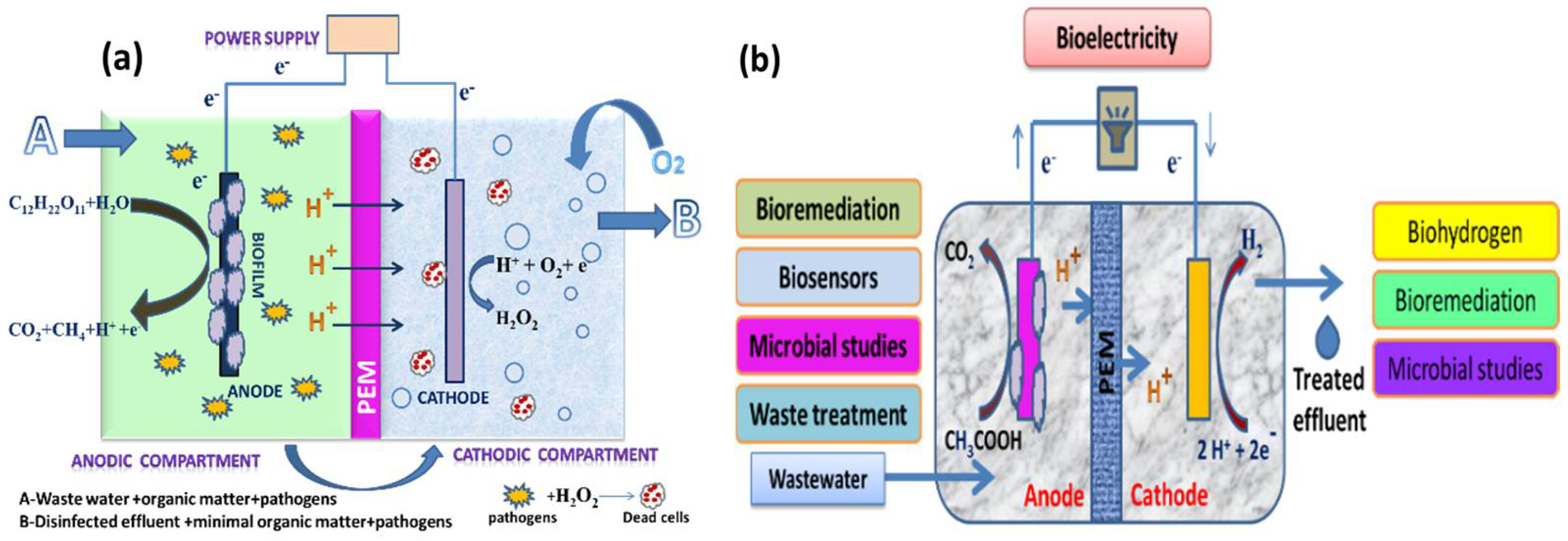
2. MFC and MEC
2.1. Single-Chambered MECs
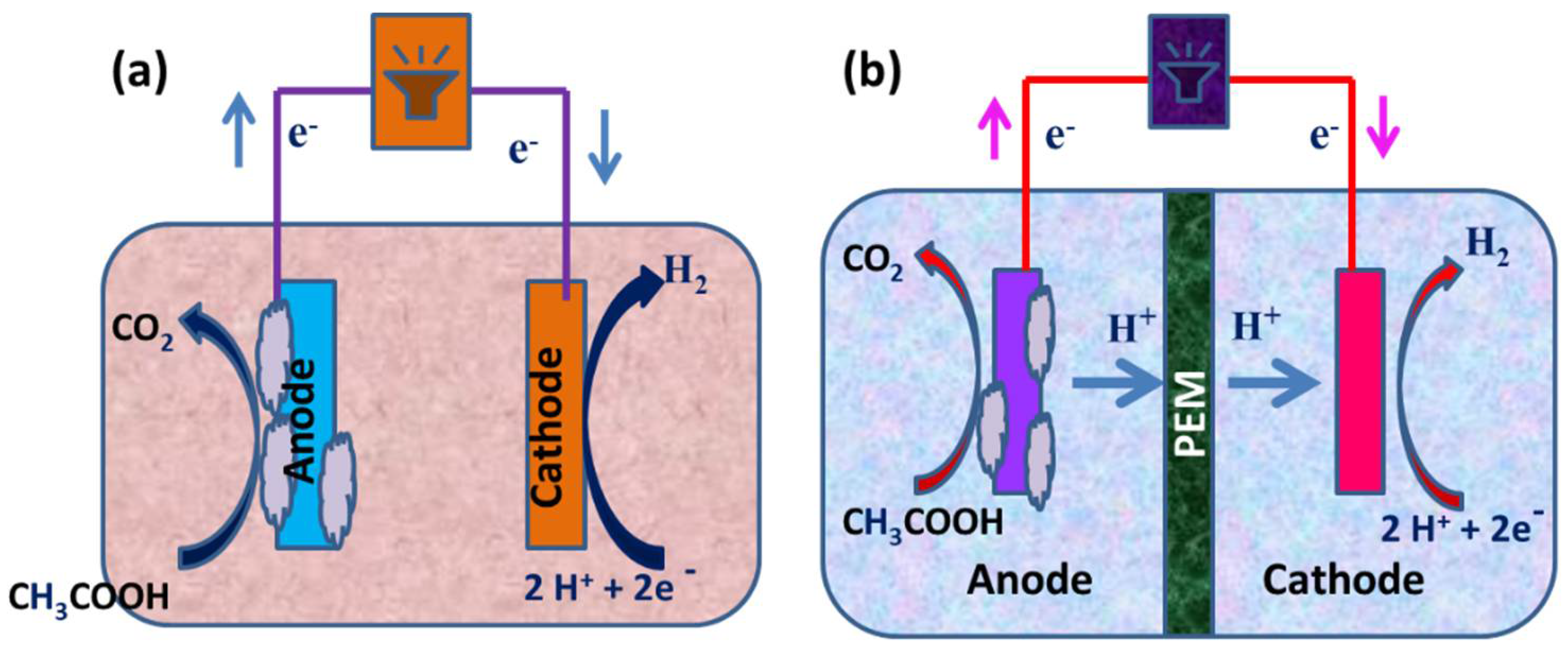
2.2. Dual-Chambered MECs
2.3. Proton Exchange Membranes
3. Applications of MEC
3.1. Electrosynthesis of Compounds
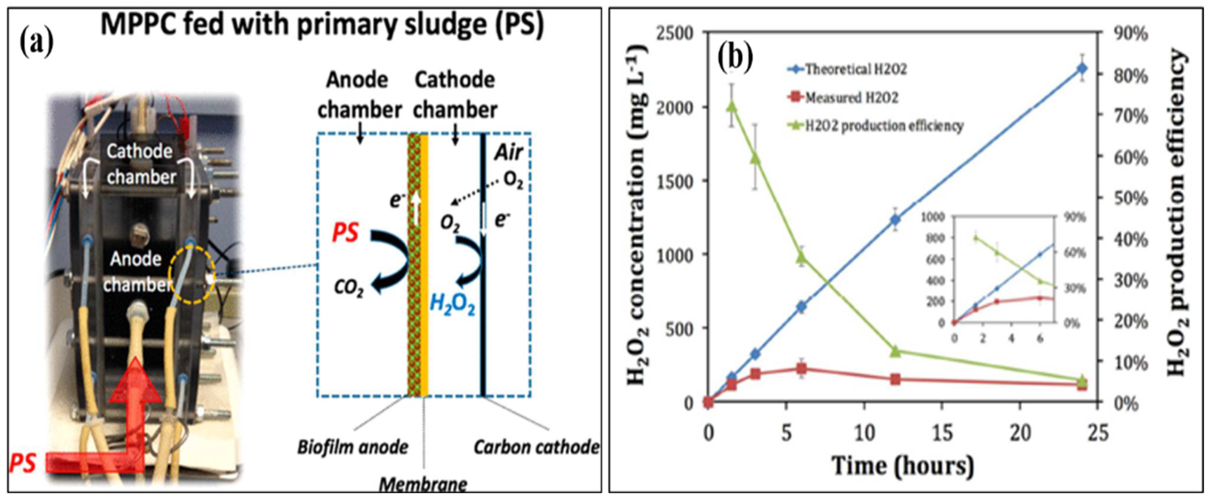
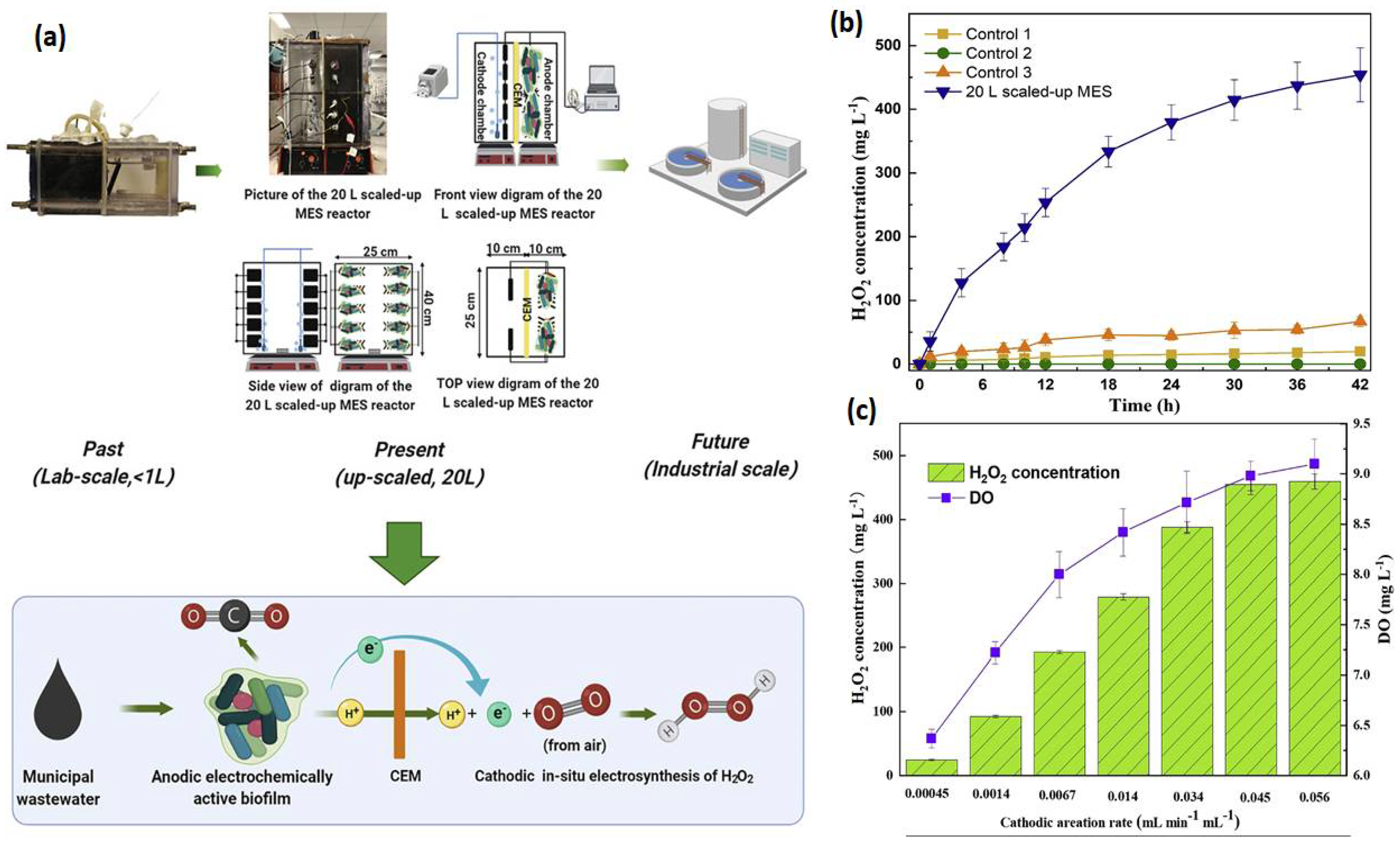
3.1.1. Hydrogen Peroxide
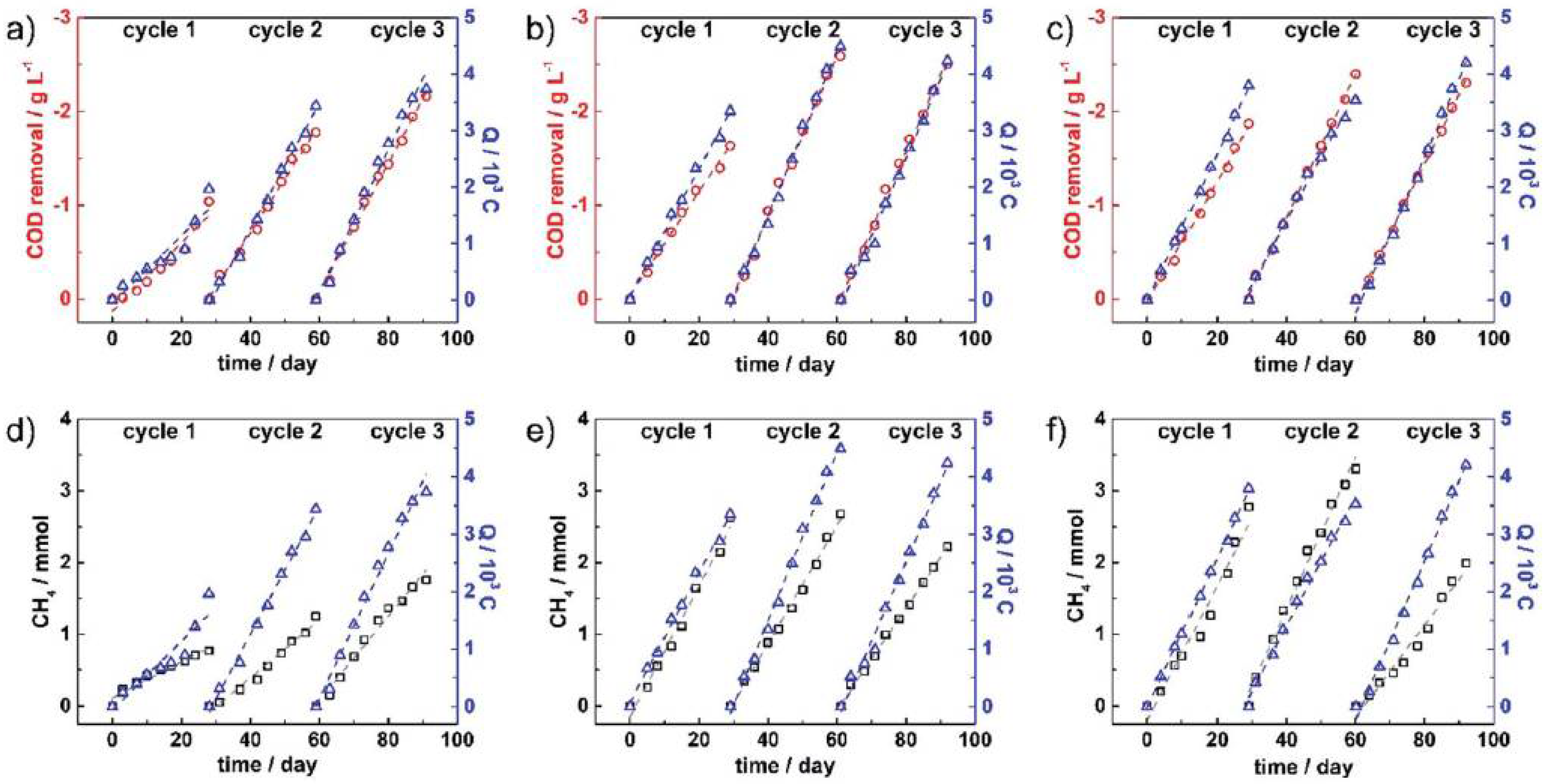
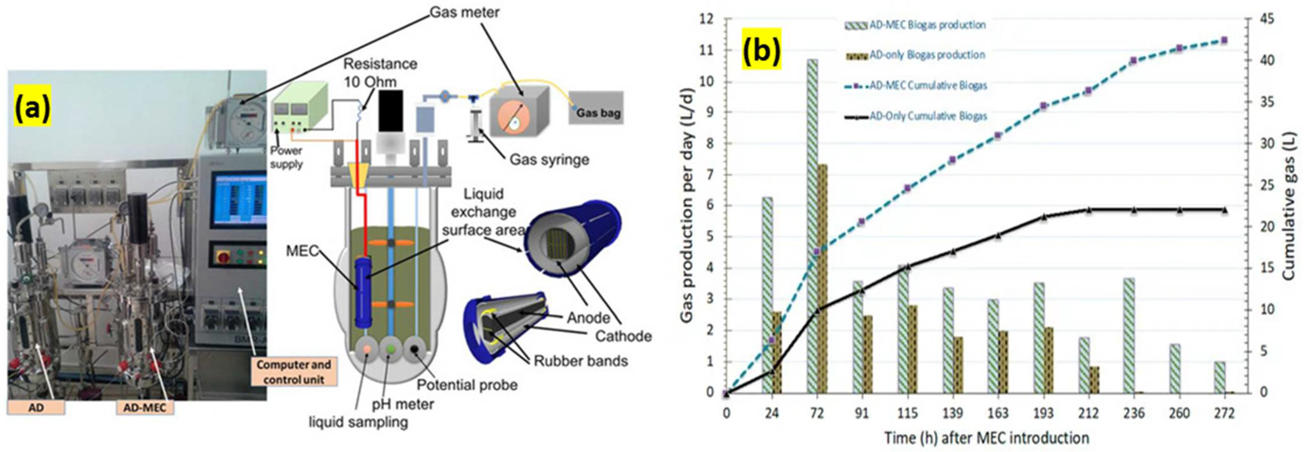
3.1.2. Methane
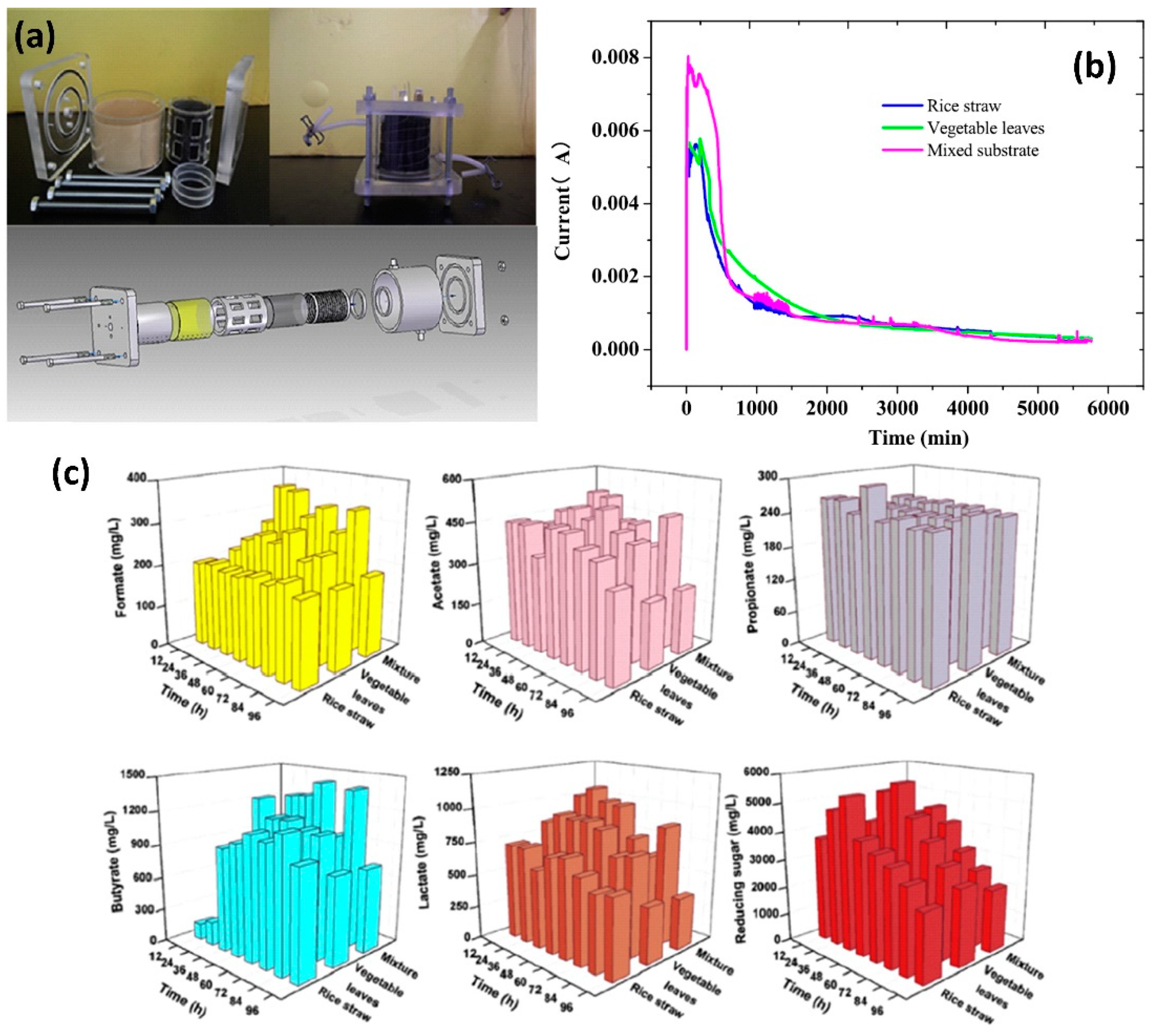
3.1.3. Hydrogen
3.2. Wastewater Treatment
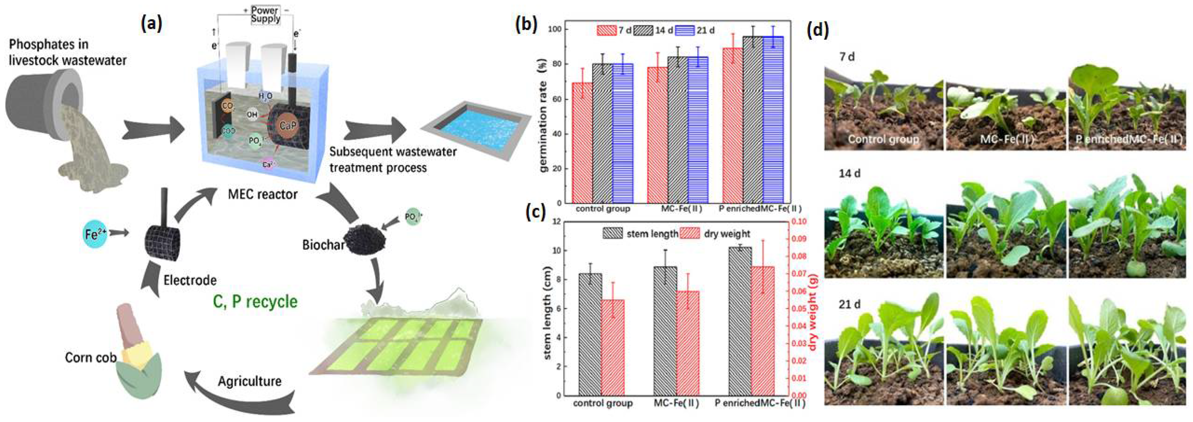
3.3. Nutrient Recovery
4. Summary and Outlook
Author Contributions
Funding
Institutional Review Board Statement
Informed Consent Statement
Data Availability Statement
Conflicts of Interest
References
- Abbasi, K.R.; Hussain, K.; Redulescu, M.; Ozturk, I. Does natural resources depletion and economic growth achieve the carbon neutrality target of the UK? A way forward towards sustainable development. Resour. Policy 2021, 74, 102341. [Google Scholar] [CrossRef]
- Ite, A.E.; Harry, T.A.; Obadimu, C.O.; Asuaiko, E.R.; Inim, I.J. Petroleum hydrocarbons contamination of surface water and groundwater in the niger delta region of Nigeria. J. Environ. Pollut. Hum. Health 2018, 6, 51–61. [Google Scholar] [CrossRef] [Green Version]
- Junne, T.; Wulff, N.; Breyer, C.; Naegler, T. Critical materials in global low-carbon energy scenarios: The case for neodymium, dysprosium, lithium, and cobalt. Energy 2020, 211, 118532. [Google Scholar] [CrossRef]
- Kang, K.; Klinghoffer, N.B.; ElGhamrawy, I.; Berruti, F. Thermochemical conversion of agroforestry biomass and solid waste using decentralized and mobile systems for renewable energy and products. Renew. Sustain. Energy Rev. 2021, 149, 111372. [Google Scholar] [CrossRef]
- Sun, C.; Zhang, H. Review of the development of first-generation redox flow batteries: Iron-chromium system. ChemSusChem 2021, 15, e202101798. [Google Scholar] [CrossRef]
- Sun, C.; Negro, E.; Vezzù, K.; Pagota, G.; Cavinato, G.; Nale, A.; Bang, Y.H.; di Notoa, V. Hybrid inorganic-organic proton-conducting membranes based on SPEEK doped with WO3 nanoparticles for application in vanadium redox flow batteries. Electrochim. Acta 2019, 309, 311–325. [Google Scholar] [CrossRef]
- Peera, S.G.; Koutavarapu, R.; Liu, C.; Rajeshkhanna, G.; Asokan, A.; Reddy, C.V. Cobalt nanoparticle-embedded nitrogen-doped carbon catalyst derived from a solid-state metal-organic framework complex for OER and HER electrocatalysis. Energies 2021, 14, 1320. [Google Scholar] [CrossRef]
- Grigoriev, S.; Fateev, V.; Bessarabov, D.; Millet, P. Current status, research trends, and challenges in water electrolysis science and technology. Int. J. Hydrogen Energy 2020, 45, 26036–26058. [Google Scholar] [CrossRef]
- Ifkovits, Z.P.; Evans, J.M.; Meier, M.C.; Papadantonakis, K.M.; Lewis, N.S. Decoupled electrochemical water-splitting systems: A review and perspective. Energy Environ. Sci. 2021, 14, 4740–4759. [Google Scholar] [CrossRef]
- Kadier, A.; Wang, J.; Chandrasekhar, K.; Abdeshahian, P.; Islam, M.A.; Ghanbari, F.; Bajpai, M.; Katoch, S.S.; Bhagawati, P.B.; Li, H.; et al. Performance optimization of microbial electrolysis cell (MEC) for palm oil mill effluent (POME) wastewater treatment and sustainable Bio-H2 production using response surface methodology (RSM). Int. J. Hydrogen Energy 2021, in press. [Google Scholar] [CrossRef]
- Kumar, S.; Kumar, V.; Kumar, R.; Malyan, S.K.; Pugazhendhi, A. Microbial fuel cells as a sustainable platform technology for bioenergy, biosensing, environmental monitoring, and other low power device applications. Fuel 2019, 255, 115682. [Google Scholar] [CrossRef]
- Segundo-Aguilar, A.; González-Gutiérrez, L.V.; Payá, V.C.; Feliu, J.; Buitrón, G.; Cercado, B. Energy and economic advantages of simultaneous hydrogen and biogas production in microbial electrolysis cells as a function of the applied voltage and biomass content. Sustain. Energy Fuels 2021, 5, 2003–2017. [Google Scholar] [CrossRef]
- Nandikes, G.; Peera, S.G.; Singh, L. Perovskite-based nanocomposite electrocatalysts: An alternative to platinum ORR catalyst in microbial fuel cell cathodes. Energies 2022, 15, 272. [Google Scholar] [CrossRef]
- Koffi, N.J.; Okabe, S. Bioelectrochemical anoxic ammonium nitrogen removal by an MFC driven single chamber microbial electrolysis cell. Chemosphere 2021, 274, 129715. [Google Scholar] [CrossRef] [PubMed]
- Peera, S.G.; Maiyalagan, T.; Liu, C.; Ashmath, S.; Lee, T.G.; Jiang, Z.; Mao, S. A review on carbon and non-precious metal-based cathode catalysts in microbial fuel cells. Int. J. Hydrog. Energy 2021, 46, 3056–3089. [Google Scholar] [CrossRef]
- Afify, A.H.; Gwad, A.A.E.; Rahman, N.A.E. Effect of power supply and bacteria on bio-hydrogen production using microbial electrolysis cells (MECs). J. Agric. Chem. Biotechn. 2017, 8, 221–224. Available online: https://www.researchgate.net/publication/352933973 (accessed on 26 November 2021).
- Zhen, G.; Lu, X.; Kumar, G.; Bakonyi, P.; Xu, K.; Zhao, Y. Microbial electrolysis cell platform for simultaneous waste biorefinery and clean electrofuels generation: Current situation, challenges and future perspectives. Prog. Energy Combust. Sci. 2017, 63, 119–145. [Google Scholar] [CrossRef]
- Anwer, A.H.; Khan, M.D.; Joshi, R. Microbial electrochemical cell: An emerging technology for waste water treatment and carbon sequestration. In Modern Age Waste Water Problems; Springer: Cham, Switzerland, 2020; pp. 339–360. [Google Scholar] [CrossRef]
- Rahimnejad, M.; Adhami, A.; Darvari, S.; Zirehpour, A.; Oh, S.-E. Microbial fuel cell as new technology for bioelectricity generation: A review. Alex Eng. J. 2015, 54, 745–756. [Google Scholar] [CrossRef] [Green Version]
- Logan, B.E.; Rossi, R.; Ragab, A.I.; Saikaly, P.E. Electroactive microorganisms in bioelectrochemical systems. Nat. Rev. Microbiol. 2019, 17, 307–319. [Google Scholar] [CrossRef]
- Liu, H.; Hu, H.; Chignell, J.; Fan, Y. Microbial electrolysis: Novel technology for hydrogen production from biomass. Biofuels 2010, 1, 129–142. [Google Scholar] [CrossRef]
- Vincent, I.; Bessarabov, D. Low cost hydrogen production by anion exchange membrane electrolysis: A review. Renew. Sust. Energy Rev. 2018, 81, 1690–1704. [Google Scholar] [CrossRef]
- Chae, K.-J.; Kim, K.-Y.; Choi, M.-J.; Yang, E.; Kim, I.S.; Ren, X.; Lee, M. Sulfonated polyether ether ketone (SPEEK)-based composite proton exchange membrane reinforced with nanofibers for microbial electrolysis cells. Chem. Eng. J. 2014, 254, 393–398. [Google Scholar] [CrossRef]
- Park, S.-G.; Chae, K.-J.; Lee, M. A sulfonated poly(arylene ether sulfone)/polyimide nanofiber composite proton exchange membrane for microbial electrolysis cell application under the coexistence of diverse competitive cations and protons. J. Membr. Sci. 2017, 540, 165–173. [Google Scholar] [CrossRef]
- Fu, L.; You, S.-J.; Yang, F.-L.; Gao, M.-M.; Fang, X.-H.; Zhang, G.-Q. Synthesis of hydrogen peroxide inmicrobial fuel cell. J. Chem. Technol. Biotechnol. 2010, 85, 715–719. [Google Scholar] [CrossRef]
- Khan, W.; Nam, J.-Y.; Woo, H.; Ryu, H.; Kim, S.; Maeng, S.K.; Kim, H.-C. A proof of concept study for wastewater reuse using bioelectrochemical processes combined with complementary post-treatment technologies. Environ. Sci. Water Res. Technol. 2019, 5, 1489. [Google Scholar] [CrossRef] [PubMed]
- Munoz-Cupa, C.; Hu, Y.; Xu, C.; Bassi, A. An overview of microbial fuel cell usage in wastewater treatment, resource recovery and energy production. Sci. Total Environ. 2021, 754, 142429. [Google Scholar] [CrossRef]
- Chung, T.H.; Meshref, M.N.; Hai, F.I.; Al-Mamun, A.; Dhar, B.R. Microbial electrochemical systems for hydrogen peroxide synthesis: Critical review of process optimization, prospective environmental applications, and challenges. Bioresour. Technol. 2020, 313, 123727. [Google Scholar] [CrossRef]
- Ghangrekar, M.M.; Chakraborty, I. Exploiting bioelectrochemical systems for wastewater treatment and value-added product recovery. In Post Treatments of Anaerobically Treated Effluents; IWA Publishing: London, UK, 2019; pp. 389–408. [Google Scholar] [CrossRef]
- Das, S.; Mishra, A.; Ghangrekar, M.M. Production of hydrogen peroxide using various metal-based catalysts in electrochemical and bioelectrochemical systems: Mini review. J. Hazardous Toxic Radioact. Waste 2020, 24, 06020001. [Google Scholar] [CrossRef]
- Hua, T.; Li, S.; Li, F.; Zhou, Q.; Ondon, B.S. Microbial electrolysis cell as an emerging versatile technology: A review on its potential application, advance and challenge. J. Chem. Technol. Biotechnol. 2019, 94, 1697–1711. [Google Scholar] [CrossRef]
- Sim, J.; An, J.; Elbeshbishy, E.; Ryu, H.; Lee, H.-S. Characterization and optimization of cathodic conditions for H2O2 synthesis in microbial electrochemical cells. Bioresour. Technol. 2015, 195, 31–36. [Google Scholar] [CrossRef]
- Ki, D.; Popat, S.C.; Rittmann, B.E.; Torres, C.I. H2O2 production in microbial electrochemical cells fed with primary sludge. Environ. Sci. Technol. 2017, 51, 6139–6145. [Google Scholar] [CrossRef] [PubMed]
- Zou, R.; Hasanzadeh, A.; Khataee, A.; Yang, X.; Xu, M.; Angelidaki, I.; Zhang, Y. General rights Scaling-up of microbial electrosynthesis with multiple electrodes for in-situ production of hydrogen peroxide. IScience 2021, 24, 102094. [Google Scholar] [CrossRef] [PubMed]
- Wang, W.; Lu, X.; Su, P.; Li, Y.; Cai, J.; Zhang, Q.; Zhou, M.; Arotiba, O. Enhancement of hydrogen peroxide production by electrochemical reduction of oxygen on carbon nanotubes modified with fluorine. Chemosphere 2020, 259, 127423. [Google Scholar] [CrossRef] [PubMed]
- Li, N.; An, J.; Zhou, L.; Li, T.; Li, J.; Feng, C.; Wang, X. A novel carbon black graphite hybrid air-cathode for efficient hydrogen peroxide production in bioelectrochemical systems. J. Power Sources 2016, 306, 495–502. [Google Scholar] [CrossRef]
- Modin, O.; Fukushi, K. Development and testing of bioelectrochemical reactors converting wastewater organics into hydrogen peroxide. Water Sci. Technol. 2012, 66, 831–836. [Google Scholar] [CrossRef] [PubMed]
- Young, M.N.; Links, M.J.; Popat, S.C.; Rittmann, B.E.; Torres, C.I. Tailoring microbial electrochemical cells for production of hydrogen peroxide at high concentrations and efficiencies. ChemSusChem 2016, 9, 3345–3352. [Google Scholar] [CrossRef]
- Chen, J.-Y.; Zhao, L.; Li, N.; Liu, H. A microbial fuel cell with the three-dimensional electrode applied an external voltage for synthesis of hydrogen peroxide from organic matter. J. Power Sources 2015, 287, 291–296. [Google Scholar] [CrossRef]
- Zhao, Q.; An, J.; Wang, S.; Wang, C.; Liu, J.; Li, N. Heterotopic formaldehyde biodegradation through UV/H2O2 system with biosynthetic H2O2. Water Environ. Res. 2019, 91, 598–605. [Google Scholar] [CrossRef]
- Rozendal, R.A.; Leone, E.; Keller, J.; Rabaey, K. Efficient hydrogen peroxide generation from organic matter in a bioelectrochemical system. Electrochem. Commun. 2019, 11, 1752–1755. [Google Scholar] [CrossRef]
- Arends, J.; Van Denhouwe, S.; Verstraete, W.; Boon, N.; Rabaey, K. Enhanced disinfection of wastewater by combining wetland treatment with bioelectrochemical H2O2 production. Bioresour. Technol. 2014, 155, 352–358. [Google Scholar] [CrossRef] [Green Version]
- Rozendal, R.A.; Jeremiasse, A.W.; Hamelers, H.V.M.; Buisman, C.J.N. Buisman, hydrogen production with a microbial biocathode. Environ. Sci. Technol. 2007, 42, 629–634. [Google Scholar] [CrossRef] [PubMed]
- Palhares, D.D.D.F.; Vieira, L.; Damasceno, J.J.R. Hydrogen production by a low-cost electrolyzer developed through the combination of alkaline water electrolysis and solar energy use. Int. J. Hydrogen Energy 2018, 43, 4265–4275. [Google Scholar] [CrossRef]
- Capuano, L. International Energy Outlook 2018 (IEO2018), U.S. Energy Inf. Adm. 2018. Available online: www.eia.gov (accessed on 1 November 2021).
- Logan, B.E.; Call, D.; Cheng, S.; Hamelers, H.; Sleutels, T.; Jeremiasse, A.W.; Rozendal, R.A. Microbial electrolysis cells for high yield hydrogen gas production from organic matter. Environ. Sci. Technol. 2008, 42, 8630–8640. [Google Scholar] [CrossRef] [PubMed]
- Seelajaroen, H.; Spiess, S.; Haberbauer, M.; Hassel, M.M.; Aljabour, A.; Thallner, S.; Guebitz, G.M.; Sariciftci, N.S. Enhanced methane producing microbial electrolysis cells for wastewater treatment using poly(neutral red) and chitosan modified electrodes. Sustain. Energy Fuels 2020, 4, 4238–4248. [Google Scholar] [CrossRef]
- Park, J.; Lee, B.; Tian, D.; Jun, H. Bioelectrochemical enhancement of methane production from highly concentrated food waste in a combined anaerobic digester and microbial electrolysis cell. Bioresour. Technol. 2018, 247, 226–233. [Google Scholar] [CrossRef]
- Van Eerten-Jansen, M.C.A.A.; Ter Heijne, A.; Buisman, C.J.N.; Hamelers, H.V.M. Microbial electrolysis cells for production of methane from CO2: Long-term performance and perspectives. Int. J. Energy Res. 2011, 36, 809–819. [Google Scholar] [CrossRef] [Green Version]
- Villano, M.; Scardala, S.; Aulenta, F.; Majone, M. Carbon and nitrogen removal and enhanced methane production in a microbial electrolysis cell. Bioresour. Technol. 2013, 130, 366–371. [Google Scholar] [CrossRef]
- Wan, C.; Zhou, L.; Xu, S.; Jin, B.; Ge, X.; Qian, X.; Xu, L.; Chen, F.; Zhan, X.; Yang, Y.; et al. Defect engineered mesoporous graphitic carbon nitride modified with AgPd nanoparticles for enhanced photocatalytic hydrogen evolution from formic acid. Chem. Eng. J. 2022, 429, 132388. [Google Scholar] [CrossRef]
- Yajie, F.; Youyu, D.; Hanjun, Z.; Jiangping, M.; Kai, X.Z.; Xiaoyuan, Z. research status of single atom catalyst in hydrogen production by photocatalytic water splitting. Chin. J. Rare Metals 2021, 45, 551–568. [Google Scholar]
- Nainamohamed, S.; Spurgeon, J.; Matheswaran, M.; Satyavolu, J. Simultaneous biohydrogen production with distillery wastewater treatment using modified microbial electrolysis cell. Int. J. Hydrogen Energy 2020, 45, 18266–18274. [Google Scholar] [CrossRef]
- Chen, J.; Xu, W.; Wu, X.; Jiaqiang, E.; Lu, N.; Wang, T.; Zuo, H. System development and environmental performance analysis of a pilot scale microbial electrolysis cell for hydrogen production using urban wastewater. Energy Convers. Manag. 2019, 193, 52–63. [Google Scholar] [CrossRef]
- Zhang, L.; Wang, Y.-Z.; Zhao, T.; Xu, T. Hydrogen production from simultaneous saccharification and fermentation of lignocellulosic materials in a dual-chamber microbial electrolysis cell. Int. J. Hydrogen Energy 2019, 44, 30024–30030. [Google Scholar] [CrossRef]
- Badia-Fabregat, M.; Rago, L.; Baeza, J.A.; Guisasola, A. Hydrogen production from crude glycerol in an alkaline microbial electrolysis cell. Int. J. Hydrogen Energy 2019, 44, 17204–17213. [Google Scholar] [CrossRef]
- Jeremiasse, A.W.; Hamelers, H.V.; Saakes, M.; Buisman, C.J. Ni foam cathode enables high volumetric H2 production in a microbial electrolysis cell. Int. J. Hydrogen Energy 2010, 35, 12716–12723. [Google Scholar] [CrossRef]
- Chen, Y.; Chen, M.; Shen, N.; Zeng, R.J. H2 production by the thermoelectric microconverter coupled with microbial electrolysis cell. Int. J. Hydrogen Energy 2016, 41, 22760–22768. [Google Scholar] [CrossRef]
- Kadier, A.; Kalil, M.S.; Abdeshahian, P.; Chandrasekhar, K.; Mohamed, A.; Azman, N.F.; Logroño, W.; Simayi, Y.; Hamid, A.A. Recent advances and emerging challenges in microbial electrolysis cells (MECs) for microbial production of hydrogen and value-added chemicals. Renew. Sustain. Energy Rev. 2016, 61, 501–525. [Google Scholar] [CrossRef]
- Hassanein, A.; Witarsa, F.; Lansing, S.; Qiu, L.; Liang, Y. Bio-electrochemical enhancement of hydrogen and methane production in a combined anaerobic digester (AD) and microbial electrolysis cell (MEC) from dairy manure. Sustainability 2020, 12, 8491. [Google Scholar] [CrossRef]
- Luo, H.; Liu, G.; Zhang, R.; Bai, Y.; Fu, S.; Hou, Y. Heavy metal recovery combined with H2 production from artificial acid mine drainage using the microbial electrolysis cell. J. Hazard. Mater. 2014, 270, 153–159. [Google Scholar] [CrossRef]
- Carmona-Martínez, A.A.; Trably, E.; Milferstedt, K.; Lacroix, R.; Etcheverry, L.; Bernet, N. Long-term continuous production of H2 in a microbial electrolysis cell (MEC) treating saline wastewater. Water Res. 2015, 81, 149–156. [Google Scholar] [CrossRef] [Green Version]
- Montpart, N.; Rago, L.; Baeza, J.A.; Guisasola, A. Hydrogen production in single chamber microbial electrolysis cells with different complex substrates. Water Res. 2015, 68, 601–615. [Google Scholar] [CrossRef]
- Wang, K.; Sheng, Y.; Cao, H.; Yan, K.; Zhang, Y. Impact of applied current on sulfate-rich wastewater treatment and microbial biodiversity in the cathode chamber of microbial electrolysis cell (MEC) reactor. Chem. Eng. J. 2017, 307, 150–158. [Google Scholar] [CrossRef]
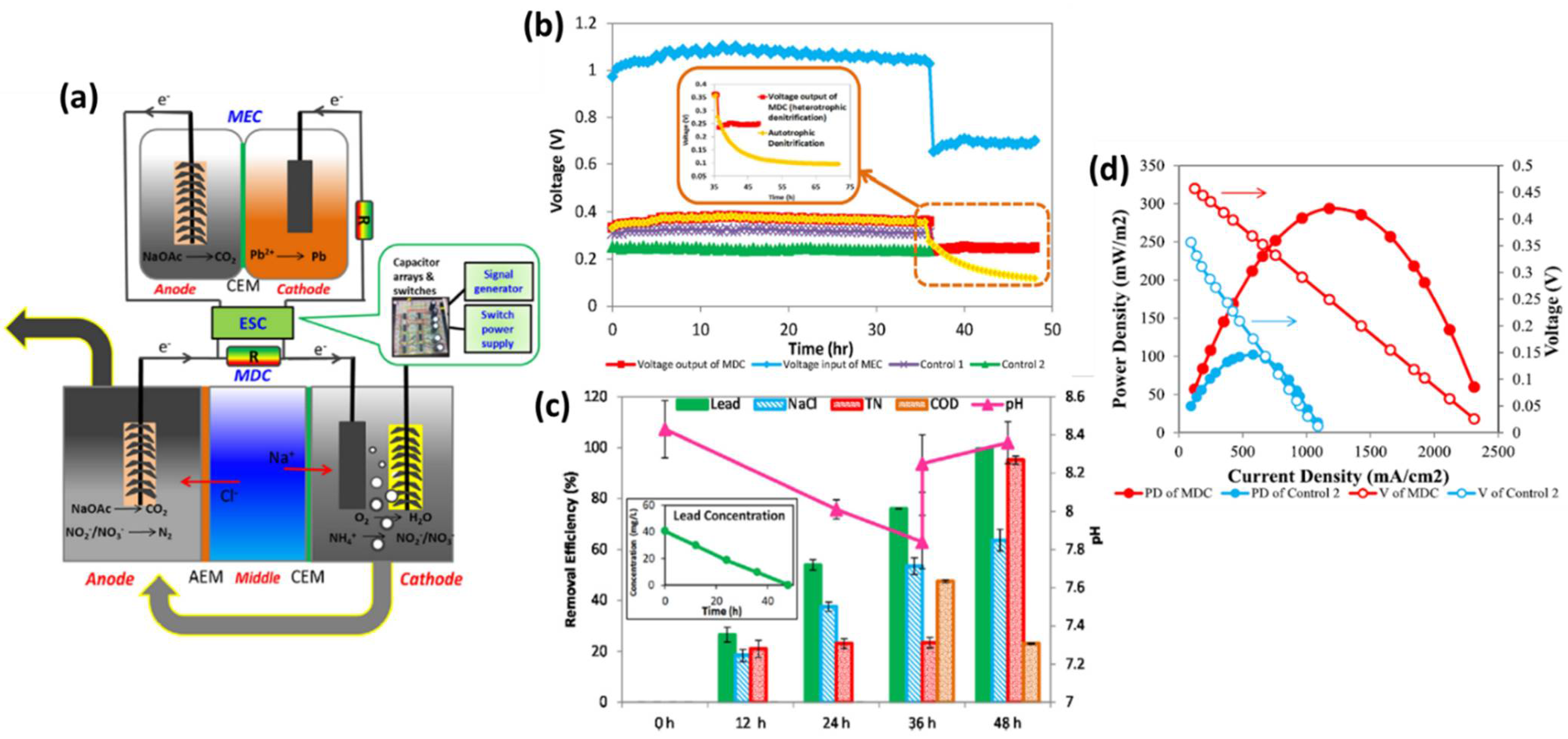
- Li, Y.; Styczynski, J.; Huang, Y.; Xu, Z.; McCutcheon, J.; Li, B. Energy-positive wastewater treatment and desalination in an integrated microbial desalination cell (MDC)-microbial electrolysis cell (MEC). J. Power Sources 2017, 356, 529–538. [Google Scholar] [CrossRef]
- Sangeetha, T.; Guo, Z.; Liu, W.; Cui, M.; Yang, C.; Wang, L.; Wang, A. Cathode material as an influencing factor on beer wastewater treatment and methane production in a novel integrated upflow microbial electrolysis cell (Upflow-MEC). Int. J. Hydrogen Energy 2016, 41, 2189–2196. [Google Scholar] [CrossRef] [Green Version]
- Escapa, A.; Gil-Carrera, L.; García, V.; Morán, A. Performance of a continuous flow microbial electrolysis cell (MEC) fed with domestic wastewater. Bioresour. Technol. 2012, 117, 55–62. [Google Scholar] [CrossRef]
- Liu, H.; Leng, F.; Guan, Y.; Yao, Y.; Li, Y.; Xu, S. Simultaneous pollutant removal and electricity generation in a combined ABR-MFC-MEC system treating fecal wastewater. Water Air Soil Pollut. 2017, 228, 179. [Google Scholar] [CrossRef]
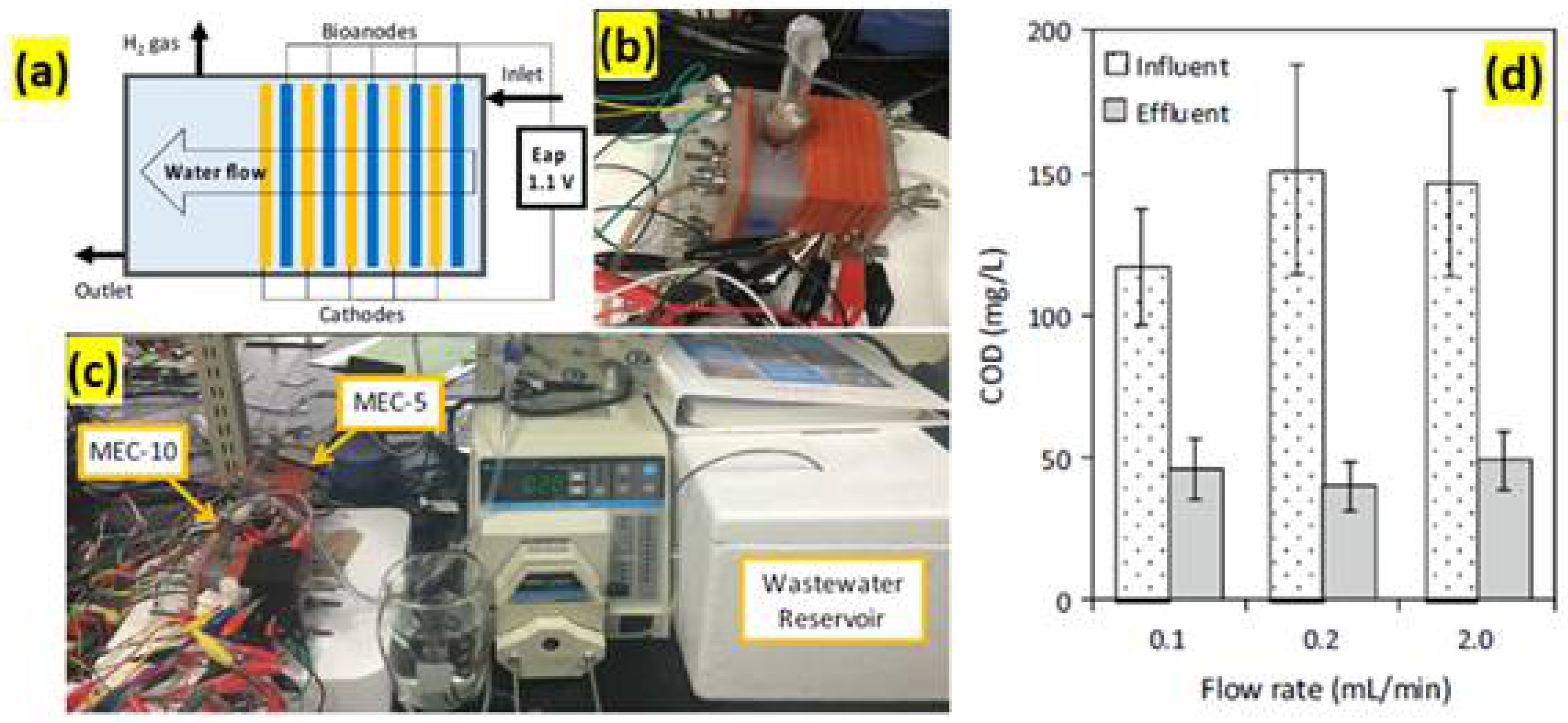
- Guo, H.; Kim, Y. Stacked multi-electrode design of microbial electrolysis cells for rapid and low-sludge treatment of municipal wastewater. Biotechnol. Biofuels 2019, 12, 23. [Google Scholar] [CrossRef]
- Cusick, R.D.; Logan, B.E. Phosphate recovery as struvite within a single chamber microbial electrolysis cell. Bioresour. Technol. 2012, 107, 110–115. [Google Scholar] [CrossRef]
- Ji, X.; Liu, X.; Yang, W.; Xu, T.; Wang, X.; Zhang, X.; Wang, L.; Mao, X.; Wang, X. Sustainable phosphorus recovery from wastewater and fertilizer production in microbial electrolysis cells using the biochar-based cathode. Sci. Total Environ. 2022, 807, 150881. [Google Scholar] [CrossRef]
- San-Martín, M.I.; Mateos, R.; Escapa, A.; Morán, A. Understanding nitrogen recovery from wastewater with a high nitrogen concentration using microbial electrolysis cells. J. Environ. Sci. Health 2019, 54, 472–477. [Google Scholar] [CrossRef]
- Li, J.; Liu, R.; Zhao, S.; Wang, S.; Wang, Y. Simultaneous desalination and nutrient recovery during municipal wastewater treatment using microbial electrolysis desalination cell. J. Clean. Prod. 2020, 261, 121248. [Google Scholar] [CrossRef]


| Sl. No | Types of Cathode Materials | H2O2 Production Rate (mg/Lh) | Operating Conditions | Energy Consumption (kWh/Kg H2O2) | Reactor Volume (mL) | Ref. |
|---|---|---|---|---|---|---|
| 1 | Graphite hybrid air cathode and carbon black | 3.3 | pH was 7, NaCl concentration was 50 mM, operated voltage was 0.6 V, and cathodic aeration rate was 1500 mL/min | 56 | 42 | [37] |
| 2 | Gas diffusion electrode | 4.2 | pH was 7, NaCl concentration was 50 mM, and operating voltage was 0.9 V | 1.8 | 18.8 | [38] |
| 3 | Vulcan carbon-coated gas diffusion electrode | 8.8 | pH was 7, NaCl concentration was 200 mM, operating voltage was 0.31 V, and cathodic aeration rate was 20 mL/min | 1.1 | 218 | [39] |
| 4 | MEC (electro-chemically tailored graphite particle) | 88.2 | pH was 7, NaSO4 concentration was 50 mM, and applied voltage was 0.4 V | 0.66 | 96 | [40] |
| 5 | Carbon black/graphite hybrid GDE | 205.4 | - | 0.6 | 150 | [41] |
| 6 | Carbon cloth | 1300 | - | 0.93 | 85 | [42] |
| 7 | Carbon felt | 340 | - | 2.5 | 41 | [43] |
| MEC Reactor | Maximum H2 Production Rate | Substrate of MEC | Current Density (A/m2) | Applied Voltage (V) | Ref. |
|---|---|---|---|---|---|
| MEC with foam cathode | 50 m3 H2 m−3 MEC d−1 | Microbial nutrient medium | 1.00 | [57] | |
| Coupled thermoelectric micro converter–MEC | 2.7 mol/mol acetate | Acetate | 0.28 | 0.16–0.83 | [58] |
| Single chambered | 1.16 m3 H2/m3 | Palm oil mill effluent | 1.0 | [59] | |
| Combined AD–MEC | 3.9 ± 0.3 m3 | Food waste | 1.35 | 0.9 | [60] |
| Dual-chambered | 0.4 ± 1.1 m3 m−3 d−1 | Acid mine drainage | 1.0 | [61] | |
| Dual-chambered | 0.9 ± 0.0 m3H2/m3 | Acetate | 199.1 ± 4.0 | [62] | |
| Single chambered | 0.94 m3 m−3 d−1 | Glycerol, milk, and starch | 150 | 0.8 | [63] |
Publisher’s Note: MDPI stays neutral with regard to jurisdictional claims in published maps and institutional affiliations. |
© 2022 by the authors. Licensee MDPI, Basel, Switzerland. This article is an open access article distributed under the terms and conditions of the Creative Commons Attribution (CC BY) license (https://creativecommons.org/licenses/by/4.0/).
Share and Cite
Radhika, D.; Shivakumar, A.; Kasai, D.R.; Koutavarapu, R.; Peera, S.G. Microbial Electrolysis Cell as a Diverse Technology: Overview of Prospective Applications, Advancements, and Challenges. Energies 2022, 15, 2611. https://doi.org/10.3390/en15072611
Radhika D, Shivakumar A, Kasai DR, Koutavarapu R, Peera SG. Microbial Electrolysis Cell as a Diverse Technology: Overview of Prospective Applications, Advancements, and Challenges. Energies. 2022; 15(7):2611. https://doi.org/10.3390/en15072611
Chicago/Turabian StyleRadhika, Devi, Archana Shivakumar, Deepak R. Kasai, Ravindranadh Koutavarapu, and Shaik Gouse Peera. 2022. "Microbial Electrolysis Cell as a Diverse Technology: Overview of Prospective Applications, Advancements, and Challenges" Energies 15, no. 7: 2611. https://doi.org/10.3390/en15072611
APA StyleRadhika, D., Shivakumar, A., Kasai, D. R., Koutavarapu, R., & Peera, S. G. (2022). Microbial Electrolysis Cell as a Diverse Technology: Overview of Prospective Applications, Advancements, and Challenges. Energies, 15(7), 2611. https://doi.org/10.3390/en15072611