Abstract
According to different mission scenarios, the UAV swarm needs to form specific topology shapes to achieve more robust system capability. The topology shaping, which will guide the UAVs autonomously to form the desired topology shape, is considered one of the most basic procedures in the UAV swarm field operations. The traditional optimization model of UAV swarm topology shaping proposed in most studies roughly represents the energy consumption by the squared Euclidean distances from initial positions to target positions of nodes. However, in practice, UAVs flying in different directions (vertical or horizontal) usually exhibits different energy consumption even though under the same moving distance. This paper proposes a more precise energy consumption model for UAV swarm topology shaping while taking the energy consumption for a UAV flying vertically upward, vertically downward, and horizontally into account. Simulation results show that the global energy consumption of the topology shaping modeled by the proposed energy consumption model is reduced by more than on average compared with that using the traditional energy consumption model. Furthermore, to further reduce the global energy consumption, a translation vector is introduced in the optimization model to obtain the optimal topology shaping position of the UAV swarm system. Newton’s method is employed to derive the translation vector which exhibits good convergence. Simulation results show that the global energy consumption of optimal topology shaping position is reduced by on average compared with that without translation.
1. Introduction
UAV swarm has drawn much attention due to its advantages of higher efficiency, better robustness, greater service scope, low cost, etc. [1], and has been widely applied in many applications such as search and rescue [2,3], disaster management [4], surveillance [5,6], remote sensing [7,8,9], precision agriculture [10,11], UAV-aided wireless communications [12,13,14], multiple targets tracking [15], etc.
In these applications, the UAV swarm needs to form a specific topology shape according to the mission requirements. For example, in a UAV-based wireless communications scenario, the performance of the aerial wireless network depends on the 3D placements (referred to as a topology shape) of UAVs [12]. In addition, the UAV swarm needs to have the ability to adjust the topology shape at any time to accommodate problems such as changing missions, node loss, regional interference, etc.
The UAV swarm topology shaping, i.e., the process of determining the optimal position of each UAV [16,17], is considered to be one of the most basic procedures in field operations of UAV swarm, which will guide the UAV swarm to autonomously form the desired topology shape without human interference.
Topology shaping is one of the most active topics in the field of unmanned aerial vehicles (UAVs) coordination, and different methods have been proposed to address the topology shaping problem of the UAV swarm [18,19,20,21]. In [22], Hoang et al. proposed a topology shaping method that focused on the alignment, rotation, and shrinkage of the topology shape, but not to change the entire topology shape. In [23], Wubben et al. presented an alternative topology shaping method by assigning each location in the initial topology to the closest UAV, which may lead to non-optimal global energy consumption. In [24], Fabra et al. adopted the same topology shaping method with Wubben et al. [23] to solve the swarm takeoff problem for UAVs of the vertical take-off and landing (VTOL) type, and take the Euclidean distances from initial position to target position as the energy consumption. In [25], Hernández et al. introduced a topology shaping scheme based on the Kuhn–Munkres (KM) algorithm to tackle the vertical takeoff of the UAV swarm, and the Euclidean distance is selected to calculate the global energy consumption. In [26], Sui et al. adopted the same KM algorithm to solve the topology shaping problem, the average center is treated as a formation’s reference center. Moreover, the particle swarm optimization algorithm employed in this paper took 50 iterations to converge. In the off-line topology shaping layer proposed by Brandão et al. [27], the current positions to desired positions straight-line distances of UAVs are adopted to solve the optimal initial topology shaping, and the geometric center of the UAV swarm are selected to calculate the relative positions. In [16], Morgan et al. proposed a distributed topology shaping method based on the distributed Auction algorithm to assign the UAVs’ initial positions to the terminal positions given by the desired shape of the swarm, the global energy consumption is defined as the sum of the squared moving distance from current location to the target position. In [28], Turpin et al. presented a concurrent assignment strategy based on the KM algorithm to address the problem of target position determination for multiple robots, in which the squared straight-line distances from initial positions to target positions are adopted to calculate the cost matrix. In [29], Gravell et al. proposed another concurrent assignment method and employed the KM algorithm to derive the optimal solution, in which the straight-line distance between the nodes’ initial state to final positions is selected to optimize the total time of topology shaping. In these topology shaping energy consumption models mentioned above, the Euclidean distances from the initial positions to target positions or the squared Euclidean distances are considered as a characteristic term for the nodes’ potential energy consumption in the process of forming topology and are used for calculating the global energy consumption of forming the specific topology shape.
However, in reality, the energy consumed by UAVs flying vertically upward, vertically downward, horizontally, and obliquely for the same distance is significantly different [30]. These studies have not considered the difference in energy consumption in different directions while modeling the energy consumption in topology shaping. Furthermore, the UAV swarm topology shaping position has a noticeable impact on global energy consumption. The proposed model mentioned above mostly ignores the effect of this aspect or set the origin of the coordinate system coincides with the geometric center (GM) of the UAV swarm, which may lead to non-optimal global energy consumption.
It is worth noting that, for energy-limited UAVs [31], the survival time is directly related to the global energy consumption, which is vital to endurance, sustainability, and task operating efficiency of the overall system [32,33,34,35]; therefore, it is essential to minimize the energy consumption in UAV missions [36,37,38], and the energy consumption of the UAV swarm should be sufficiently considered in the topology shaping process to strengthen the robustness and survivability of the swarm system.
The energy consumption of a UAV is composed of two main components, namely the communication-related energy consumption, i.e., the energy consumption of computing, communication, etc., and the propulsion energy consumption to ensure that the UAV remains at altitude and supports its motion [39]. In general, communication-related energy consumption is much smaller than the propulsion energy consumption [40], thus communication-related energy consumption is ignored in this paper.
Given the wide variety of UAVs, each with specific physical characteristics, deriving a generic parametric propulsion energy consumption model under different operating conditions is a challenging task. The propulsion energy consumption of a UAV mainly depends on the velocity and location of the UAV. So far, research on the energy consumption of UAV is relatively limited and can be divided into three categories, namely, the experimental-driven heuristic energy model based on measured/simulated data, the theoretical-driven energy model by kinematic and aircraft theory, and the simple application of an existing energy model of a ground vehicle or robot to a UAV [40]. In [41], Franco et al. simply expressed the propulsion energy consumption of a UAV as the integral of power over time, the lack of closed-form expression limits its application. In [31], Singgih et al. considered the battery status of UAVs, flight altitude, etc., in solving the multi-UAV surveillance routing problem, but the authors do not analyze the energy consumption during UAV flight in depth. In [42], Morbidi et al. proposed a propulsion energy consumption model for a quadrotor by analyzing the electrical model of the brushless DC motor to solve the minimum-energy path-planning problem. A theoretical-driven propulsion energy consumption model was proposed by Liu et al. [43]. The authors modeled the propulsion energy consumption by analyzing the aerodynamic principles of UAV flight with a relatively low accuracy prediction of energy consumption compared with the experiment results. In [39], Zeng et al. derived another theoretical-driven propulsion energy consumption model based on the results in aircraft literature by assuming that the UAV flies at a constant altitude. Gao et al. [40] verified the accuracy of the model proposed in [39] by experiments, but the application of this model is limited to the 2-dimensional. In [44], Arani et al. adopted the propulsion energy consumption model proposed by Zeng et al. in [39] to determine the three-dimensional (3D) energy-efficient trajectories of UAVs. In [45], Prasetia et al. presented an experimental-driven energy consumption model based on experimental data to predict the energy consumption of horizontal moving flight, vertical flight, and hovering. They collected and analyzed data to fit the propulsion energy consumption curve of the UAV by regression analysis. In [30], Abeywickrama et al. recorded and analyzed the energy consumption of hovering, horizontal movement, and vertical movement by measuring the voltage and current of the UAV through experiments; however, the authors did not study the energy consumption in oblique flight. In [46], Zhen et al. did not specifically calculate the propulsion energy consumption of the UAV, but by taking the lift forces of the UAV in upward, downward, oblique upward, oblique downward, and level flight as the weights in the flight path planning. Through the force analysis, it can be seen that the energy consumption of the UAV in each direction is different due to the different lift forces. In [47], Wu et al. proposed a new energy consumption model which defined the energy consumption of oblique flight based on the empirical energy consumption of vertical flight and horizontal flight obtained in [32]; however, this energy consumption model has not been experimentally validated. A more specific experimental-driven model of propulsion energy consumption was presented by Dietrich et al. in [48]. With the experimental data, the authors fitted not only the propulsion energy consumption curves for level flight, hovering, and vertical flight, but also the curves for an oblique flight of the UAV. These papers have investigated the problem of modeling the energy consumption of a single UAV in flight from three perspectives and have contributed to more accurate energy consumption models of UAVs. Further, in this paper, to achieve the global energy consumption optimization in the process of topology shaping more accurately, the energy consumption models with different directions of the UAV are introduced in the global energy consumption model of topology shaping.
Note that the theoretical-driven energy model uses a rather complex model based on aerodynamic theory involving many implicit parameters that are difficult to interpret and difficult to use [40]. Thus in our manuscript, the experimental-driven heuristic energy model based on measured data has been adopted to simplify the topology shaping energy consumption model. In fact, many factors impact the propulsion energy consumption of a UAV. From the analysis of the results in the above literature, it is noted that the UAV propulsion energy consumption cannot be predicted quite accurately either by theoretical analysis or by fitting the experimental data.
This manuscript mainly focuses on the problem of minimum energy consumption in the topology shaping process. Previous studies on this problem simply take the Euclidean distance as the energy consumption without fully considering the difference of energy consumption of UAVs flying in different directions; therefore, in this paper, we further optimize the energy consumption model of topology shaping by introducing the energy consumption in different flight directions of multiple UAVs.
In this paper, to address the problems mentioned above, an improved energy consumption model for topology shaping is proposed to evaluate the global energy consumption of the UAV in forming the desired topology shape. Based on the proposed energy consumption model, the concept of optimal topology shaping position is introduced to further optimize global energy consumption. First, the novel energy consumption model for topology shaping is presented by combining the empirical energy consumption of upward, downward, oblique, and level flight with the Euclidean distance that the UAV traveled. Then the topology shaping is derived through the existing assignment method based on the proposed model. Second, a translation vector is introduced to investigate the relation between topology shaping position and global energy consumption, Newton’s method is employed to derive the translation vector, and the optimal topology shaping position is obtained with minimum global energy consumption by translating the topology shape position.
The main contributions of this article are summarized as follows.
- A more precise energy consumption model for UAV swarm topology shaping is proposed. The energy consumption is specifically subdivided into upward, downward, oblique, and level flight. Compared with the traditional energy consumption model of topology shaping, the proposed model is closer to realistic scenarios. The simulation results show that the global energy consumption of the topology shaping modeled by the proposed energy consumption model is reduced by more than on average compared with that using the traditional energy consumption model.
- To further optimize the global energy consumption of the following topology forming process, a translation vector is introduced to optimize the topology shaping position. Moreover, Newton’s method is implemented to solve the optimized model. Simulation results show that the global energy consumption of the translated topology shaping is reduced by on average compared with that without translation.
The rest of this paper is organized as follows. The traditional energy consumption model for topology shaping is described in Section 2. The proposed energy consumption model is presented in Section 3. The introduction of a translation vector for optimizing the position of the topology shaping and its solution are described in Section 4. Section 5 presents the simulations and results, followed by the conclusions and discussions presented in Section 6.
2. Traditional Optimization Model for Topology Shaping
In this section, the traditional energy consumption model for topology shaping is presented in detail.
In many situations, as shown in Figure 1, a UAV swarm in a three dimensional (3D) Euclidean space is required to achieve some specific topology shape at certain places due to mission changing or loss of UAV, which calls for the topology shaping of the UAV swarm.
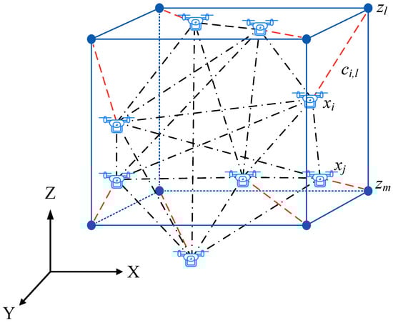
Figure 1.
An example of topology shaping for UAV swarm.
Consider a UAV swarm consisting of N UAVs, let denote the coordinate matrix of the initial topology, where is the 3D coordinate vector of the ith UAV in the initial topology. The coordinate matrix of the target topology is denoted by , where is the 3D coordinate vector of the lth target position derived by the target topology shape.
According to [16,25,28,29], the traditional energy consumption from node i to position in the topology forming process is assumed to be only related to the squared Euclidean distance between and . The coordinate origin and standard direction of the target coordinate system are assumed to be overlapped with the initial coordinate system, thus
where denotes the Euclidean norm. The energy consumption matrix, consisting of the energy consumption of all possible assignment relationships, is denoted by .
Let denote the optimal assignment relationship matrix derived by traditional energy consumption model, where denotes the assignment between and , means that the target position of is , otherwise, . Only when will the in be chosen to calculate the global energy consumption under traditional optimization model . Thus can be expressed by
where denotes the entrywise matrix norm.
In traditional topology shaping optimization models, the topology shaping from initial topology to target topology is generally transformed into an assignment problem and solved by employing the KM algorithm [25,27,28] or by adopting the Auction algorithm [16]. Both algorithms will obtain the minimum global energy consumption [49], which is not described in detail in this paper.
3. Proposed Topology Shaping Optimization Model
In this section, to address the shortcomings of the traditional energy consumption model, which does not sufficiently consider the energy consumption difference between upward, downward, oblique, and level flight, a novel energy consumption model for topology shaping is proposed and described in detail.
In this paper, we focus on the global energy consumption optimization of topology shaping for UAV swarms. In contrast, the impacts on energy consumption of computing, communication, control, different flying speeds, different flying altitudes, wind, etc., are not taken into account [40]. To simplify the model, the experimental results obtained through the experimentally driven model are integrated into the energy consumption model for UAV topology shaping.
As shown in Figure 2, the energy consumption of a UAV flying from to can be subdivided based on the flying directions [30,46,48]. Let , , correspond to the energy consumption of a level flight, vertical upward flight, vertical downward flight, respectively. Let correspond to the energy consumption of an oblique flight, in which is the angle between and the horizontal plane as shown in Figure 2. It can be seen that, if the UAV is flying obliquely upwards, then , and the corresponding energy consumption is . If the UAV is flying obliquely downwards, , the corresponding energy consumption of the UAV is . If , then , the corresponding energy consumption of the UAV is . If , then , the corresponding energy consumption of the UAV is . If , then , the corresponding energy consumption of the UAV is . It is worth noting that, if , the corresponding energy consumption of the UAV, i.e., the value of , varies with , but not much [48]. In this paper, to simplify the model, the energy consumption of the UAV flying obliquely upwards and downwards is set to two constant values according to the experimental results presented in [30].
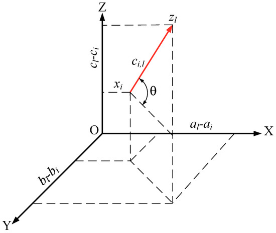
Figure 2.
The energy consumption for a UAV flying from to .
Then, for a UAV flying from to , the energy consumption in the topology forming process can be approximately expressed by
The energy consumption matrix, consisting of the energy consumption of all possible assignment relationships, is denoted as
Let denote the assignment relationship matrix, and denotes the assignment between and , , which means that the target position of is , otherwise, . Then the global energy consumption in the topology forming process while considering the difference of energy consumption by UAVs flying to different direction can be expressed by
In this paper, the purpose is to study the global energy optimization of topology shaping with no consideration of energy consumption such as computation, communication, control, etc.; therefore, in this paper, the KM algorithm is employed to solve the topology shaping. Without loss of generality, based on the energy consumption matrix and the KM algorithm, the optimal assignment relationship from the initial topology to the target topology is assumed as .
4. Optimal Topology Shaping Position
In this section, the concept of optimal topology shaping position is introduced to further optimize global energy consumption. Based on the optimization model proposed in Section 3, a translation vector is introduced to develop the optimization model for the optimal topology shaping position, and Newton’s method which has good convergence is adopted to solve the model.
4.1. Introduction of Translation Vector
In this paper, the topology shaping position refers to the desired positions of nodes for shaping the desired topology, which can be denoted by the origin of the coordinate system. For solving the optimal assignment from the initial coordinates to target coordinates, most studies [16,25,28,29] have assumed that the coordinate origin of the target coordinate system overlaps with one of the initial coordinate systems or coincides with the geometric center (GM) of the initial UAV swarm topology.
In fact, the topology shaping position does affect the global energy consumption in the process of topology forming. More specifically, the global energy consumption may not be minimal when the initial and target coordinate systems are overlapped.
To figure out the relationship between the topology shaping position and the global energy consumption based on the optimal assignment relationship , two cases of topology shaping are given. For a visual illustration, assume that the initial topology and the target topology are in a plane, as shown in Figure 3, the gray dots () represent the initial positions of nodes, and the target topology shape is a square.
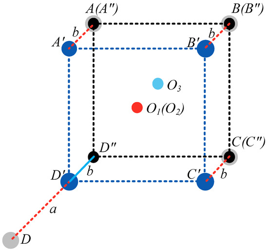
Figure 3.
Comparison of energy consumption with different shaping positions.
In the first case, the topology is shaped based on the common assumption that the origin of the target topology shape coincides with the geometric center (GM) of the initial UAV swarm topology shape, i.e., is overlapped with . The target topology is shaped by blue dots (). The global energy consumption in topology shaping process is denoted by , which is the sum of the squared distances from the initial positions to target positions, as indicated by red dashed lines in Figure 3, i.e., .
In the second case, the target topology is shaped by black dots (), and the origin (geometric center) of the target topology is . The global energy consumption in topology shaping process is denoted as , thus .
Obviously, , which means the global energy consumption may not be minimal in the assumption that the origin of the initial and the target topology are overlapped.
In order to find the optimal topology shaping position based on the optimal assignment , a vector which translates the target topology is introduced.
4.2. Solution of Translation Vector
After translation, the position l in the target topology is translated to , thus the energy consumption from node i in the initial topology to the translated position , denoted as , can be expressed by
The energy consumption matrix is reformulated into , where
Based on the optimal assignment relationship matrix and Equation (5), the global energy consumption in topology shaping is reformulated into
The problem of finding the optimal shaping position can be expressed by
in which the translation vector in is to be derived.
The minimal global energy consumption for finding optimal topology shaping position is expressed by
which is a function of .
Let
The optimal translation vector can be derived from Equation (11) by employing the Newton’s method, specifically,
Let
It is obviously that W is independent of . The gradient of with respect to is calculated by
According to Equation (12), all the second partial derivatives of exist and are continuous on the definition domain of the function. Then, the Hessian matrix of with respect to is expressed by
In practical application, generally, the Newton direction (the inverse of Hessian matrix) can be calculated by solving Equation (16) for reducing the computational complexity.
In Equation (16), is the vector needed to be solved. The specific procedure of obtaining translation vector is summarized in Algorithm 1.
| Algorithm 1: Obtaining translation vector |
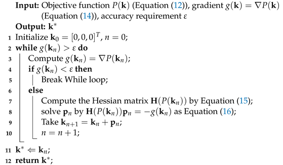 |
After obtaining the translation vector , each target position is translated by to obtain the translated coordinates matrix, , which is the optimal shaping position of target topology.
The specific process of the proposed topology shaping method is as follows:
- Obtain the optimal coordinate assignment relationship by the KM algorithm or the Auction algorithm [16,25,28,29].
- Derive the translation vector using Algorithm 1.
- Achieve the optimal topology shaping based on the optimal assignment relationship and translated coordinate matrix .
5. Simulations and Results
In this section, the proposed method is verified by simulation. First, the simulation settings are described in detail, followed by the validation of the topology shaping method with the proposed energy consumption model. The effect of topology shaping position on global energy consumption, the energy consumption in the topology shaping process, and convergence of the algorithm are discussed in detail. All simulation results are obtained from Matlab (R2021b 64-bit version) running on a personal computer (CPU 12th Gen Intel(R) Core(TM) i9-12900K @3.19 GHz, 128 GB RAM, Windows 11 Pro).
5.1. Simulation Settings
Ten typical 3D target topology shapes of UAV swarm, namely T, V, arrow, circle, cross, cube, ellipse, line, square, triangle, are employed to verify the proposed model by simulations. The number of nodes in the V-shaped UAV swarm is 31, while the number of nodes in other shapes is 32. The size of the target topology, i.e., the maximum value of the absolute value of the target topology coordinates, is limited to 400. The initial positions of the UAVs are randomly distributed in 3D space of × × . The mapping relationship from the initial topology to target topology is derived by the KM algorithm. The mapping relationships denoted by are generated based on the traditional topology shaping energy consumption model as described in Section 2. Another set of mapping relationships denoted by is derived from the proposed topology shaping energy consumption model as described in Section 3. The accuracy requirement in deriving translation vector by Algorithm 1 is . The corresponding simulation parameters are shown in Table 1.

Table 1.
Simulation settings.
According to the energy consumption model for quadrotor UAVs proposed by Abeywickrama et al. [30], the typical energy consumption of a quadrotor flying in different directions is listed in Table 2. According to the experiment results presented in [48], the energy consumption of flying obliquely downwards is at the same level of flying vertically downwards, and the energy consumption of flying obliquely upwards is at the same level of flying vertically upwards. Thus in the simulation, the energy consumption of flying vertically downwards and upwards are taken as the energy consumption of flying obliquely downwards and upwards, respectively.
Table 2.
Energy consumption of UAVs flying in different directions.
5.2. Global Energy Consumption of Different Model
In the case of cube-shaped target topology, 100 sets of simulations were conducted to compare the global energy consumption between the traditional topology shaping method and the proposed topology shaping method, as shown in Figure 4. In each simulation, the initial topology nodes’ coordinates are randomly generated while the target topology coordinates are fixed. The cost matrix of the proposed method is derived by Equation (3) based on Table 2. The cost matrix of the traditional method is derived by Equation (1). The global energy consumption of the traditional method is derived based on the mapping relationship from traditional method and the cost matrix of the proposed method. Simulation results show that the global energy consumption of the proposed method is far below the traditional energy consumption model.
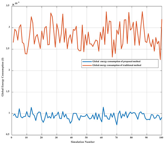
Figure 4.
Global energy consumption comparison between the proposed model and the traditional model in the cube-shaped topology.
To compare the energy consumption of the proposed method and the traditional method more sufficiently, 100 simulations were performed for each of the 10 target topologies. The global energy consumption ratios of the proposed and traditional methods were recorded. A box plot of the global energy consumption ratio has been created by Matlab’s function, as shown in Figure 5. The red dots, which are plotted as individual points in Figure 5, are the results that are distant from other simulation results. Simulation results show that the average ratio of the global energy consumption of the proposed method to the traditional method is at in the case of cube-shaped target topology, while average ratios of the other nine topology shapes are in the range of to . The energy consumption ratio is different because the cube is a true 3D topology, while the other topologies are distributed on a certain plane. Simulation results show that, compared with the proposed method, the mapping relationship derived from the traditional method is non-optimal.
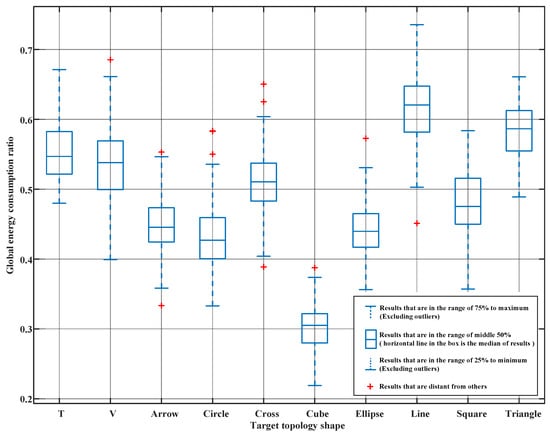
Figure 5.
Box plot of the global energy consumption ratio between the proposed model and the traditional model.
5.3. Evaluation of the Effect of Translation Vectors
In this section, the effectiveness of the topology shaping method after the introduction of translation vectors is verified. Then the global energy consumption difference of the topology shaping after the introduction of translation vectors is compared.
5.3.1. Validation of the Topology Shaping after Introduction of Translation Vector
An intuitive simulation of the impact of the translation vector on the topology shaping position is shown in Figure 6 based on the cube-shaped target topology. The purple circles represent the initial positions of nodes. The dashed green line is the outline of the initial position of the target topology without translation. The red asterisks represent the target positions after translation. The solid blue line outlines the optimal topology shape, which is translated by based on the initial target topology. The dashed blue line is the mapping relationship from the initial positions of UAVs to the translated target locations of the target topology shape.
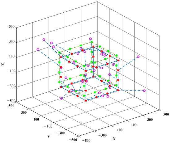
Figure 6.
The topology shaping position of the cube with and without the translation vector.
Another simulation based on the V-shaped target topology is conducted and the simulation result is shown in Figure 7 and Figure 8. The initial positions of the UAVs are denoted by purple circles, the initial position of target topology shape result is denoted by the bright green asterisks. The topology shape after translation is indicated by the red asterisks. From Figure 6 and Figure 8 we can find that the desired topology shape is successfully achieved after the introduction of the translation vector. The optimal position of the target topology is often below the initial position, which is due to the lower energy consumption of the UAV flying downward.
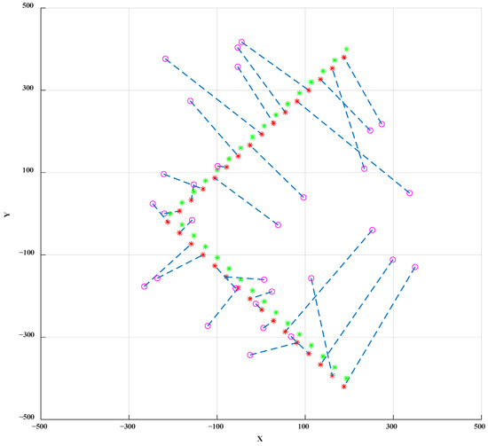
Figure 7.
The X–Y perspective of the V-shaped topology.
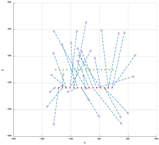
Figure 8.
The X–Z perspective of the V-shaped topology.
5.3.2. The Impact of Translation Vectors on Global Energy Consumption
In this section, to verify the impact on global energy consumption of translation vector , 100 simulations were conducted for the cube-shaped topology based on the proposed method. Simulation results show that the global energy consumption of the topology shaping after translation of vector is lower than that without translation as shown in Figure 9.
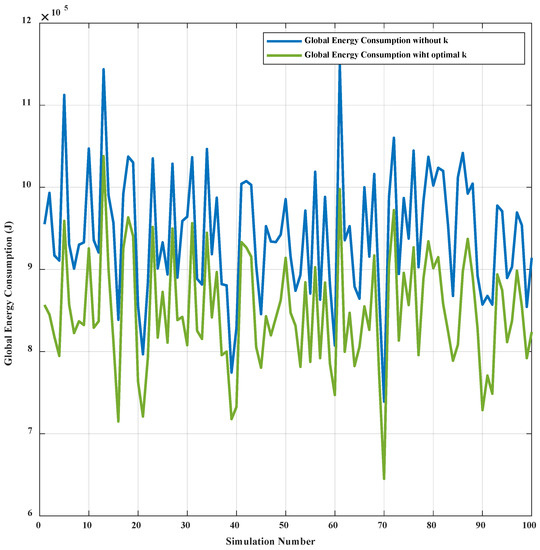
Figure 9.
The global energy consumption comparison with and without the translation vector based on the proposed method in the cube-shaped topology.
To better demonstrate the energy consumption of the target topology after translating the optimal vectors, 100 independent simulations were conducted for the 10 typical target topologies. The statistics of the simulation results are shown in Figure 10. The bottom and top of the box indicate the 25th and 75th percentile of the simulation results, respectively. The line in the box indicates the median of the simulation results. The red dots, which are plotted as individual points in Figure 10, are the results that are distant from other simulation results. Simulation results show that, based on the proposed method, the global energy consumption after translation is reduced by on average compared with that without translation in the case of cube-shaped topology. After translation, the global energy consumption of other target topology shapes is reduced on average by the range of to .
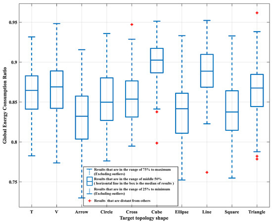
Figure 10.
Box plot of global energy consumption ratio with and without the translation vector based on the proposed method.
5.4. Convergence Analysis
Newton’s method has been employed to derive the translation vector. The convergence of Newton’s method is analyzed in this section. Figure 11 is obtained by an average of 100 sets of simulations in the ten typical target topologies. Simulation results show that the averaged global energy consumption tends to be stable after 8 iterations.
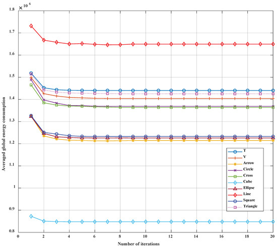
Figure 11.
Convergence speed of the proposed algorithm of ten typical target topologies.
More specifically, the average error ratio between the fourth iteration and the optimal solution is less than ; therefore, in practice, a four-iteration setup can be used to achieve a compromise between complexity and performance.
5.5. Computational Complexity
For a UAV swarm system consisting of N nodes, Newton’s method requires the calculation of the Hessian matrix and its inverse matrix, thus the computational complexity of Algorithm 1 is [50]. The computational complexity of the KM algorithm is [21]; therefore, the computational complexity of the proposed method is .
The computational times of the ten typical target topologies have been obtained by simulations, as shown in Figure 12. Simulation results show that the average computation time for solving each topology shaping instance is s; however, the computation time can be reduced by reducing the number of iterations of Newton’s method.
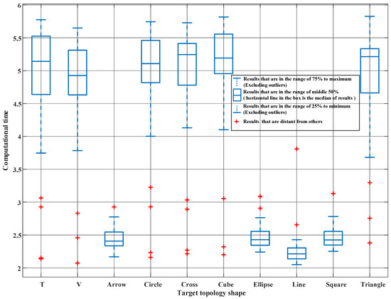
Figure 12.
Box plot of the computational time for solving the topology shaping of each instance.
5.6. Evaluation of the Impact of the Number of UAVs on System Performance
To verify the impact of the number of UAVs on the performance of the system in our proposed and traditional methods, a series of simulations have been conducted in which the number of UAVs in the swarm increases from 20 to 200. In the simulations, both the initial topology and the target topology are randomly distributed in 3D × × space. Fifty independent simulations have been performed for each UAV swarm. Figure 13 is a box plot of the simulation results of the global energy consumption ratio using our proposed and traditional energy consumption models. Simulation results show that the average global energy consumption ratio is below and decreases gradually as the number of UAVs increases. Figure 14 is a box plot of the simulation results of the energy consumption ratio with and without the translation vector . Simulation results show that the global energy consumption is reduced by on average after the introduction of the translation vector in swarms with different numbers of UAVs.
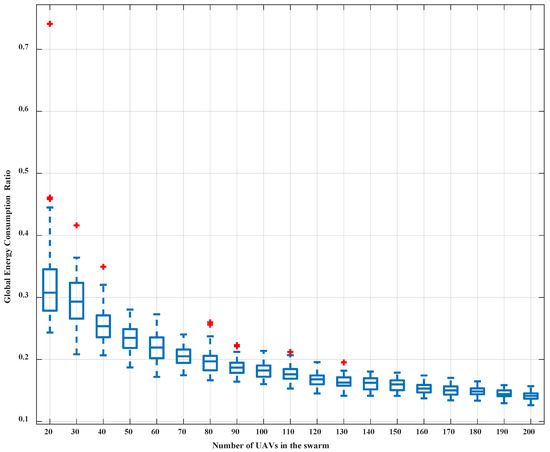
Figure 13.
Global energy consumption ratio statistics of swarms with different numbers of UAVs in the proposed and traditional method.
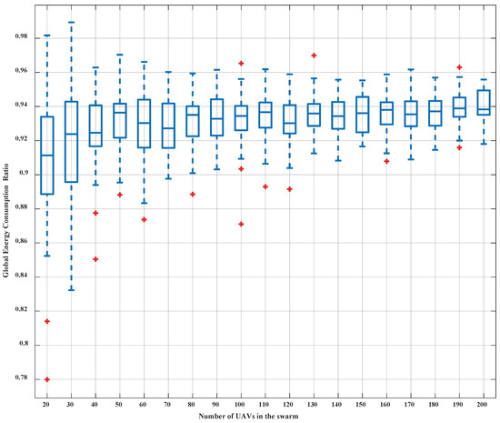
Figure 14.
Global energy consumption ratio statistics of swarms with different numbers of UAVs in proposed method with and without translation vector.
6. Conclusions and Discussion
The topology shaping, which guides UAVs to form the desired topology shape autonomously, is considered one of the most basic procedures in the UAV swarm field operations. For energy-limited UAVs, the survival time is directly related to the global energy consumption, which is vital to the overall system’s endurance, sustainability, and task operating efficiency; therefore, it is crucial to minimize the energy consumption in the UAV swarm topology shaping process. In this paper, a more precise energy consumption model for topology shaping is proposed to address the problem that the traditional energy consumption model does not sufficiently consider the difference in energy consumption of UAV flying in each direction. Subsequently, a translation vector is introduced to optimize the global energy consumption. Simulation results show that, for the 10 target topologies under test, the proposed method reduces the global energy consumption by more than on average compared with the traditional method. The global energy consumption of the translated topology shaping is reduced by at least on average compared with that without translation.
With the improvement and validation of the theoretical-driven energy consumption models of UAVs, the energy consumption optimization problem of topology shaping can be more accurately solved, which is the next step of our research.
Author Contributions
Conceptualization, Y.Y., X.Z. and K.Q.; Funding acquisition, X.Z. and K.Q.; Methodology, Y.Y. and J.Z.; Supervision, X.Z., B.L. and K.Q.; Visualization, Y.Y. and J.Z.; Writing—original draft, Y.Y. and J.Z.; Writing—review and editing, Y.Y., X.Z., B.L. and K.Q. All authors have read and agreed to the published version of the manuscript.
Funding
This work was funded by the Central Military Commission (grant number 61403120404).
Institutional Review Board Statement
Not applicable.
Informed Consent Statement
Not applicable.
Data Availability Statement
The data presented in this study are openly available in Github at https://github.com/Ethanxegg/geco (accessed on 17 February 2022).
Acknowledgments
The authors would like to thank the editor and the anonymous reviewers for their careful reading and valuable suggestions that helped to improve the quality of this manuscript.
Conflicts of Interest
There is no conflict of interest to report.
References
- Otto, A.; Agatz, N.; Campbell, J.; Golden, B.; Pesch, E. Optimization approaches for civil applications of unmanned aerial vehicles (UAVs) or aerial drones: A survey. Networks 2018, 72, 411–458. [Google Scholar] [CrossRef]
- Li, L.; Xu, S.; Nie, H.; Mao, Y.; Yu, S. Collaborative Target Search Algorithm for UAV Based on Chaotic Disturbance Pigeon-Inspired Optimization. Appl. Sci. 2021, 11, 7358. [Google Scholar] [CrossRef]
- Zimroz, P.; Trybała, P.; Wróblewski, A.; Góralczyk, M.; Szrek, J.; Wójcik, A.; Zimroz, R. Application of UAV in search and rescue actions in underground mine—A specific sound detection in noisy acoustic signal. Energies 2021, 14, 3725. [Google Scholar] [CrossRef]
- Janik, P.; Zawistowski, M.; Fellner, R.; Zawistowski, G. Unmanned Aircraft Systems Risk Assessment Based on SORA for First Responders and Disaster Management. Appl. Sci. 2021, 11, 5364. [Google Scholar] [CrossRef]
- Kabir, R.H.; Lee, K. Wildlife monitoring using a multi-uav system with optimal transport theory. Appl. Sci. 2021, 11, 4070. [Google Scholar] [CrossRef]
- Ahmed, N.; Pawase, C.J.; Chang, K. Distributed 3-D Path Planning for Multi-UAVs with Full Area Surveillance Based on Particle Swarm Optimization. Appl. Sci. 2021, 11, 3417. [Google Scholar] [CrossRef]
- Haque, M.E.; Asikuzzaman, M.; Khan, I.U.; Ra, I.H.; Hossain, M.S.; Shah, S.B.H. Comparative Study of IoT-Based Topology Maintenance Protocol in a Wireless Sensor Network for Structural Health Monitoring. Remote Sens. 2020, 12, 2358. [Google Scholar] [CrossRef]
- Liu, X.; Yin, J.; Zhang, S.; Ding, B.; Guo, S.; Wang, K. Range-Based Localization for Sparse 3-D Sensor Networks. IEEE Internet Things J. 2019, 6, 753–764. [Google Scholar] [CrossRef]
- Brook, A.; Ben-Dor, E. Automatic Registration of Airborne and Spaceborne Images by Topology Map Matching with SURF Processor Algorithm. Remote Sens. 2011, 3, 65–82. [Google Scholar] [CrossRef] [Green Version]
- Aslan, M.F.; Durdu, A.; Sabanci, K.; Ropelewska, E.; Gültekin, S.S. A Comprehensive Survey of the Recent Studies with UAV for Precision Agriculture in Open Fields and Greenhouses. Appl. Sci. 2022, 12, 1047. [Google Scholar] [CrossRef]
- Velusamy, P.; Rajendran, S.; Mahendran, R.K.; Naseer, S.; Shafiq, M.; Choi, J.G. Unmanned Aerial Vehicles (UAV) in Precision Agriculture: Applications and Challenges. Energies 2022, 15, 217. [Google Scholar] [CrossRef]
- Zeng, Y.; Zhang, R.; Lim, T.J. Wireless communications with unmanned aerial vehicles: Opportunities and challenges. IEEE Commun. Mag. 2016, 54, 36–42. [Google Scholar] [CrossRef] [Green Version]
- He, X.; Yu, W.; Xu, H.; Lin, J.; Yang, X.; Lu, C.; Fu, X. Towards 3D deployment of UAV base stations in uneven terrain. In Proceedings of the 2018 27th International Conference on Computer Communication and Networks (ICCCN), Hangzhou, China, 30 July–2 August 2018; pp. 1–9. [Google Scholar]
- Siddiqui, A.B.; Aqeel, I.; Alkhayyat, A.; Javed, U.; Kaleem, Z. Prioritized User Association for Sum-Rate Maximization in UAV-Assisted Emergency Communication: A Reinforcement Learning Approach. Drones 2022, 6, 45. [Google Scholar] [CrossRef]
- Shakhatreh, H.; Sawalmeh, A.H.; Al-Fuqaha, A.; Dou, Z.; Almaita, E.; Khalil, I.; Othman, N.S.; Khreishah, A.; Guizani, M. Unmanned aerial vehicles (UAVs): A survey on civil applications and key research challenges. IEEE Access 2019, 7, 48572–48634. [Google Scholar] [CrossRef]
- Morgan, D.; Subramanian, G.P.; Chung, S.J.; Hadaegh, F.Y. Swarm assignment and trajectory optimization using variable-swarm, distributed auction assignment and sequential convex programming. Int. J. Robot. Res. 2016, 35, 1261–1285. [Google Scholar] [CrossRef] [Green Version]
- Kamel, M.A.; Yu, X.; Zhang, Y. Formation control and coordination of multiple unmanned ground vehicles in normal and faulty situations: A review. Annu. Rev. Control 2020, 49, 128–144. [Google Scholar] [CrossRef]
- Do, H.T.; Hua, H.T.; Nguyen, M.T.; Nguyen, C.V.; Nguyen, H.T.; Nguyen, H.T.; Nguyen, N.T. Formation control algorithms for multiple-UAVs: A comprehensive survey. EAI Endorsed Trans. Ind. Netw. Intell. Syst. 2021, 8, e3. [Google Scholar] [CrossRef]
- Ziquan, Y.; Zhang, Y.; Jiang, B.; Jun, F.; Ying, J. A review on fault-tolerant cooperative control of multiple unmanned aerial vehicles. Chin. J. Aeronaut. 2022, 35, 1–18. [Google Scholar]
- Wang, X.; Zeng, Z.; Cong, Y. Multi-agent distributed coordination control: Developments and directions via graph viewpoint. Neurocomputing 2016, 199, 204–218. [Google Scholar] [CrossRef]
- Yang, Y.; Zhang, X.; Zhou, J.; Li, B.; Qin, K. A Relative Coordinate-Based Topology Shaping Method for UAV Swarm with Low Computational Complexity. Appl. Sci. 2022, 12, 2631. [Google Scholar] [CrossRef]
- Hoang, V.T.; Phung, M.D.; Dinh, T.H.; Zhu, Q.; Ha, Q.P. Reconfigurable multi-uav formation using angle-encoded pso. In Proceedings of the 2019 IEEE 15th International Conference on Automation Science and Engineering (CASE), Vancouver, BC, Canada, 22–26 August 2019; pp. 1670–1675. [Google Scholar]
- Wubben, J.; Aznar, P.; Fabra, F.; Calafate, C.T.; Cano, J.C.; Manzoni, P. Toward secure, efficient, and seamless reconfiguration of UAV swarm formations. In Proceedings of the 2020 IEEE/ACM 24th International Symposium on Distributed Simulation and Real Time Applications (DS-RT), Prague, Czech Republic, 14–16 September 2020; pp. 1–7. [Google Scholar] [CrossRef]
- Fabra, F.; Wubben, J.; Calafate, C.T.; Cano, J.C.; Manzoni, P. Efficient and coordinated vertical takeoff of UAV swarms. In Proceedings of the 2020 IEEE 91st Vehicular Technology Conference (VTC2020-Spring), Antwerp, Belgium, 25–28 May 2020; pp. 1–5. [Google Scholar]
- Hernández, D.; Cecília, J.M.; Calafate, C.T.; Cano, J.C.; Manzoni, P. The Kuhn-Munkres algorithm for efficient vertical takeoff of UAV swarms. In Proceedings of the 2021 IEEE 93rd Vehicular Technology Conference (VTC2021-Spring), Helsinki, Finland, 25–28 April 2021; pp. 1–5. [Google Scholar]
- Sui, Z.; Pu, Z.; Yi, J. Optimal UAVs formation transformation strategy based on task assignment and Particle Swarm Optimization. In Proceedings of the 2017 IEEE International Conference on Mechatronics and Automation (ICMA), Takamatsu, Japan, 6–9 August 2017; pp. 1804–1809. [Google Scholar] [CrossRef]
- Brandão, A.S.; Sarcinelli-Filho, M. On the guidance of multiple uav using a centralized formation control scheme and delaunay triangulation. J. Intell. Robot. Syst. 2016, 84, 397–413. [Google Scholar] [CrossRef]
- Turpin, M.; Michael, N.; Kumar, V. Concurrent assignment and planning of trajectories for large teams of interchangeable robots. In Proceedings of the 2013 IEEE International Conference on Robotics and Automation, Karlsruhe, Germany, 6–10 May 2013; pp. 842–848. [Google Scholar] [CrossRef]
- Gravell, B.; Summers, T. Concurrent goal assignment and collision-free trajectory generation for multiple aerial robots. IFAC-PapersOnLine 2018, 51, 75–81. [Google Scholar] [CrossRef]
- Abeywickrama, H.V.; Jayawickrama, B.A.; He, Y.; Dutkiewicz, E. Comprehensive energy consumption model for unmanned aerial vehicles, based on empirical studies of battery performance. IEEE Access 2018, 6, 58383–58394. [Google Scholar] [CrossRef]
- Singgih, I.K.; Lee, J.; Kim, B.I. Node and Edge Drone Surveillance Problem with Consideration of Required Observation Quality and Battery Replacement. IEEE Access 2020, 8, 44125–44139. [Google Scholar] [CrossRef]
- Abeywickrama, H.V.; Jayawickrama, B.A.; He, Y.; Dutkiewicz, E. Empirical power consumption model for uavs. In Proceedings of the 2018 IEEE 88th Vehicular Technology Conference (VTC-Fall), Chicago, IL, USA, 27–30 August 2018; pp. 1–5. [Google Scholar]
- Okulski, M.; Ławryńczuk, M. How Much Energy Do We Need to Fly with Greater Agility? Energy Consumption and Performance of an Attitude Stabilization Controller in a Quadcopter Drone: A Modified MPC vs. PID. Energies 2022, 15, 1380. [Google Scholar] [CrossRef]
- Shakoor, S.; Kaleem, Z.; Baig, M.I.; Chughtai, O.; Duong, T.Q.; Nguyen, L.D. Role of UAVs in Public Safety Communications: Energy Efficiency Perspective. IEEE Access 2019, 7, 140665–140679. [Google Scholar] [CrossRef]
- Steup, C.; Parlow, S.; Mai, S.; Mostaghim, S. Generic Component-Based Mission-Centric Energy Model for Micro-Scale Unmanned Aerial Vehicles. Drones 2020, 4, 63. [Google Scholar] [CrossRef]
- Alyassi, R.; Khonji, M.; Chau, S.C.K.; Elbassioni, K.; Tseng, C.M.; Karapetyan, A. Autonomous recharging and flight mission planning for battery-operated autonomous drones. arXiv 2017, arXiv:1703.10049. [Google Scholar]
- Babazadeh, R.; Selmic, R. Distance-Based Multiagent Formation Control with Energy Constraints Using SDRE. IEEE Trans. Aerosp. Electron. Syst. 2019, 56, 41–56. [Google Scholar] [CrossRef]
- Horla, D.; Cieślak, J. On obtaining energy-optimal trajectories for landing of UAVs. Energies 2020, 13, 2062. [Google Scholar] [CrossRef] [Green Version]
- Zeng, Y.; Xu, J.; Zhang, R. Energy Minimization for Wireless Communication with Rotary-Wing UAV. IEEE Trans. Wirel. Commun. 2019, 18, 2329–2345. [Google Scholar] [CrossRef] [Green Version]
- Gao, N.; Zeng, Y.; Wang, J.; Wu, D.; Zhang, C.; Song, Q.; Qian, J.; Jin, S. Energy model for UAV communications: Experimental validation and model generalization. China Commun. 2021, 18, 253–264. [Google Scholar] [CrossRef]
- Di Franco, C.; Buttazzo, G. Energy-aware coverage path planning of UAVs. In Proceedings of the 2015 IEEE International Conference on Autonomous Robot Systems and Competitions, Vila Real, Portugal, 8–10 April 2015; pp. 111–117. [Google Scholar]
- Morbidi, F.; Cano, R.; Lara, D. Minimum-energy path generation for a quadrotor UAV. In Proceedings of the 2016 IEEE International Conference on Robotics and Automation (ICRA), Stockholm, Sweden, 16–21 May 2016; pp. 1492–1498. [Google Scholar] [CrossRef] [Green Version]
- Liu, Z.; Sengupta, R.; Kurzhanskiy, A. A power consumption model for multi-rotor small unmanned aircraft systems. In Proceedings of the 2017 International Conference on Unmanned Aircraft Systems (ICUAS), Miami, FL, USA, 13–16 June 2017; pp. 310–315. [Google Scholar]
- Arani, A.H.; Azari, M.M.; Hu, P.; Zhu, Y.; Yanikomeroglu, H.; Safavi-Naeini, S. Reinforcement Learning for Energy-Efficient Trajectory Design of UAVs. IEEE Internet Things J. 2021. [Google Scholar] [CrossRef]
- Prasetia, A.S.; Wai, R.J.; Wen, Y.L.; Wang, Y.K. Mission-Based Energy Consumption Prediction of Multirotor UAV. IEEE Access 2019, 7, 33055–33063. [Google Scholar] [CrossRef]
- Zhen, L.; Li, M.; Laporte, G.; Wang, W. A vehicle routing problem arising in unmanned aerial monitoring. Comput. Oper. Res. 2019, 105, 1–11. [Google Scholar] [CrossRef]
- Wu, Q.; Shen, F.; Wang, Z.; Ding, G. 3D spectrum mapping based on ROI-driven UAV deployment. IEEE Netw. 2020, 34, 24–31. [Google Scholar] [CrossRef]
- Dietrich, T.; Krug, S.; Zimmermann, A. An empirical study on generic multicopter energy consumption profiles. In Proceedings of the 2017 Annual IEEE International Systems Conference (SysCon), Montreal, QC, Canada, 24–27 April 2017; pp. 1–6. [Google Scholar]
- Wubben, J.; Cecilia, J.M.; Calafate, C.T.; Cano, J.C.; Manzoni, P. Evaluating the effectiveness of takeoff assignment strategies under irregular configurations. In Proceedings of the 2021 IEEE/ACM 25th International Symposium on Distributed Simulation and Real Time Applications (DS-RT), Valencia, Spain, 27–29 September 2021; pp. 1–7. [Google Scholar] [CrossRef]
- Nesterov, Y. Introductory Lectures on Convex Optimization: A Basic Course; Springer Science & Business Media: New York, NY, USA, 2003; Volume 87. [Google Scholar]
Publisher’s Note: MDPI stays neutral with regard to jurisdictional claims in published maps and institutional affiliations. |
© 2022 by the authors. Licensee MDPI, Basel, Switzerland. This article is an open access article distributed under the terms and conditions of the Creative Commons Attribution (CC BY) license (https://creativecommons.org/licenses/by/4.0/).