
Experimental Investigation of the Hydrodynamic Performance of Land-Fixed Nearshore and Onshore Oscillating Water Column Systems with a Thick Front Wall

 , ,
, ,  ,
,  , ,
, ,
Abstract
:1. Introduction
- In particular, the convenience and safety of access for installation and maintenance to the power plant make it more convenient for coastal and near-shore devices, as well as eliminating the need for mooring systems and subsea power cables.
- Gearboxes are not required because an air turbine is used.
- Construction and maintenance become more available when they are planned to be erected on the shore or as part of pre-existing ocean structures [10].
- In particular, access to the power plant becomes more convenient for coastal and nearshore devices, and it eliminates the need for mooring systems and undersea electric cables.
2. Experimental Campaign
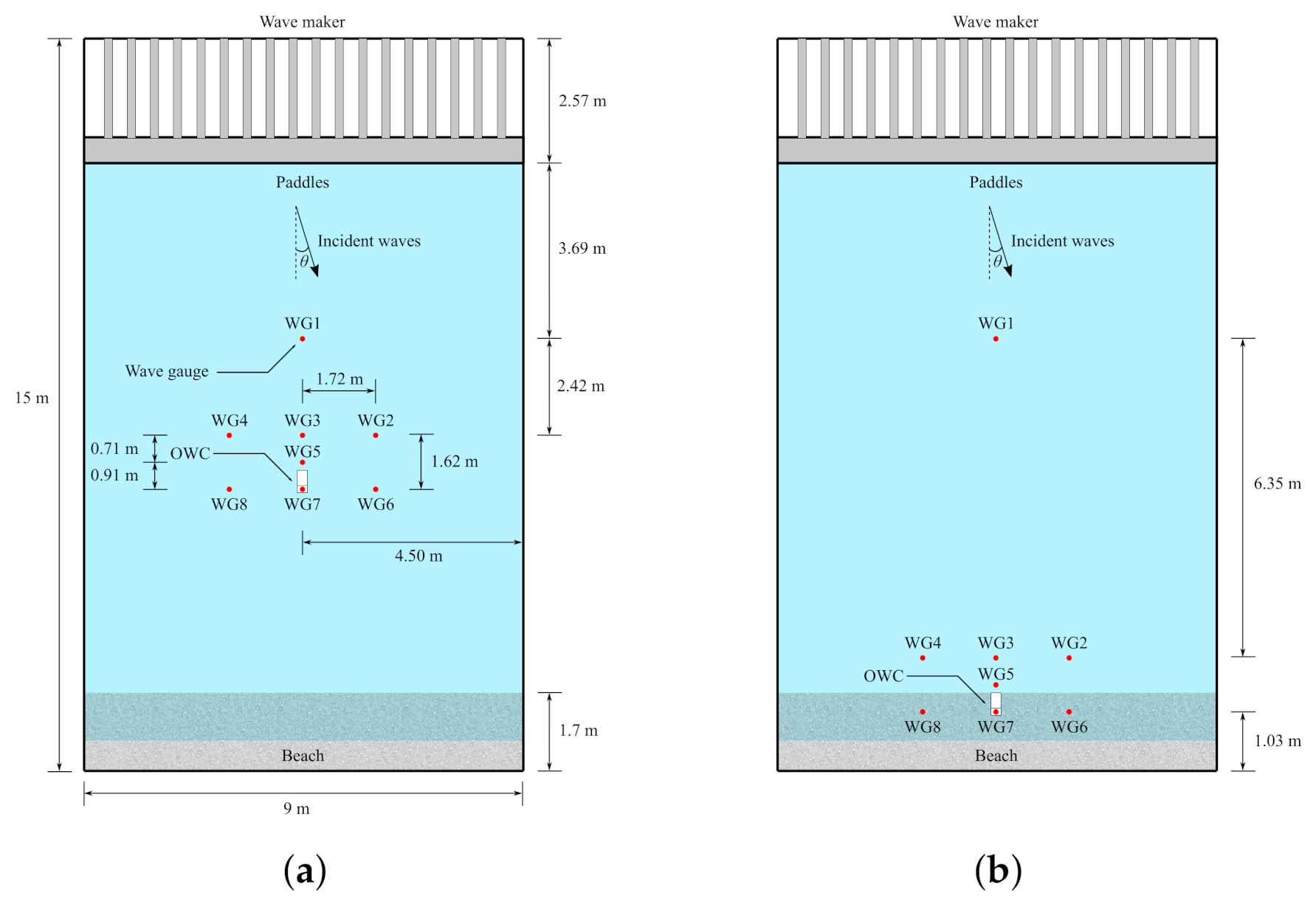
2.1. Test Facility
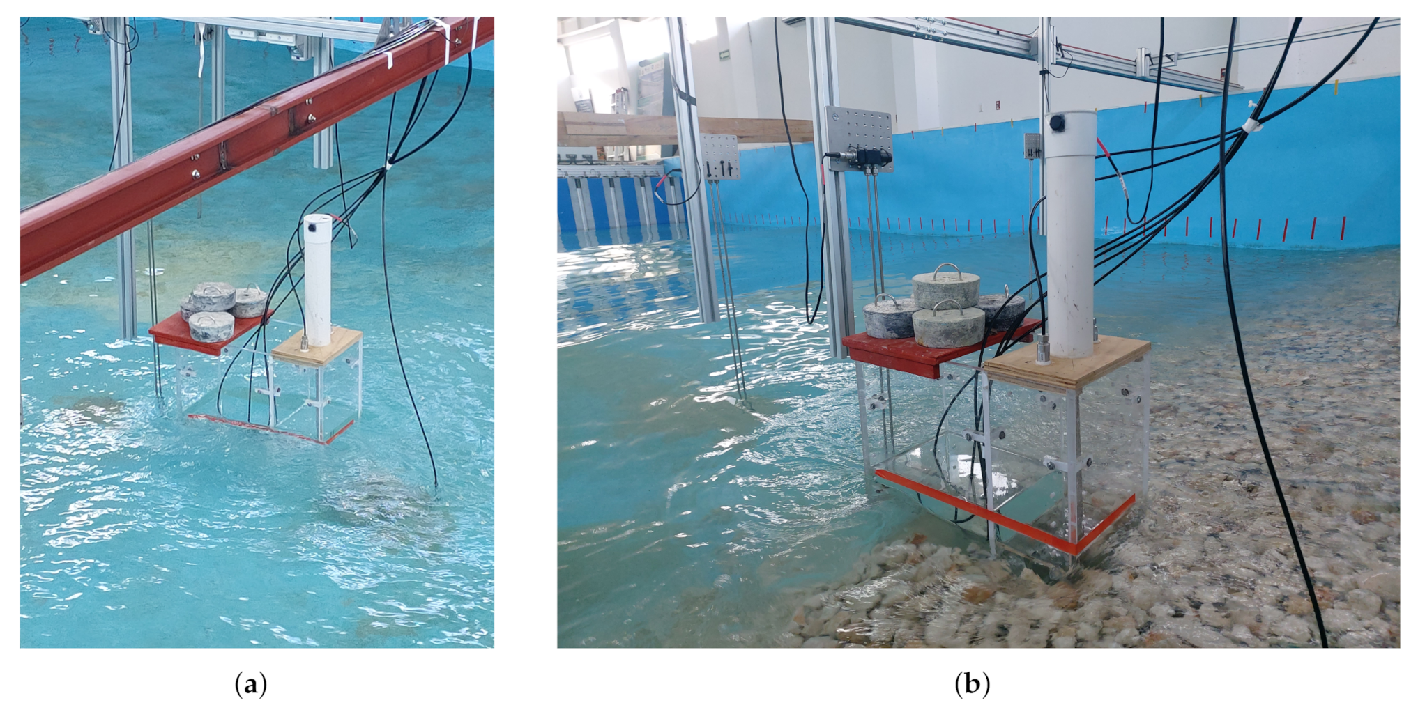
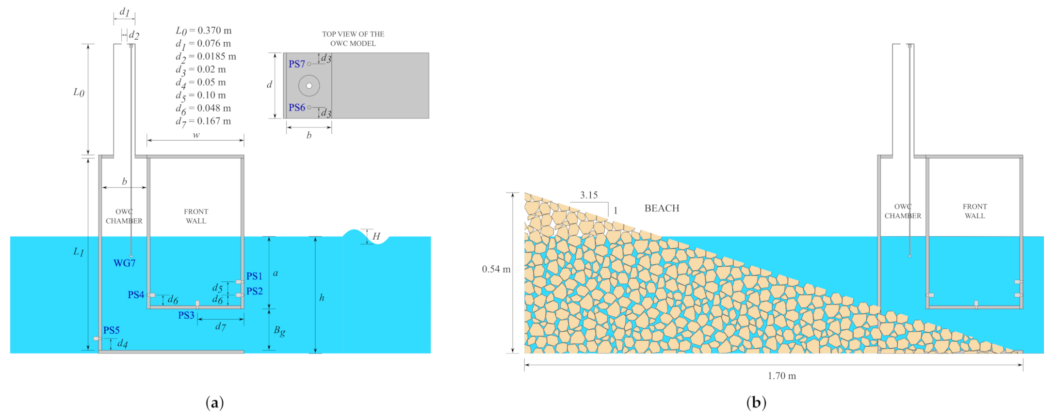
2.2. Test Model
2.3. Instrumentation
2.4. Experimental Set-Up
3. Hydrodynamic Parameters
3.1. Dimensional Analysis
3.2. Hydrodynamic Efficiency
3.3. Dimensionless Hydrodynamic Quantities
4. Results and Discussion
4.1. Nearshore OWC Model
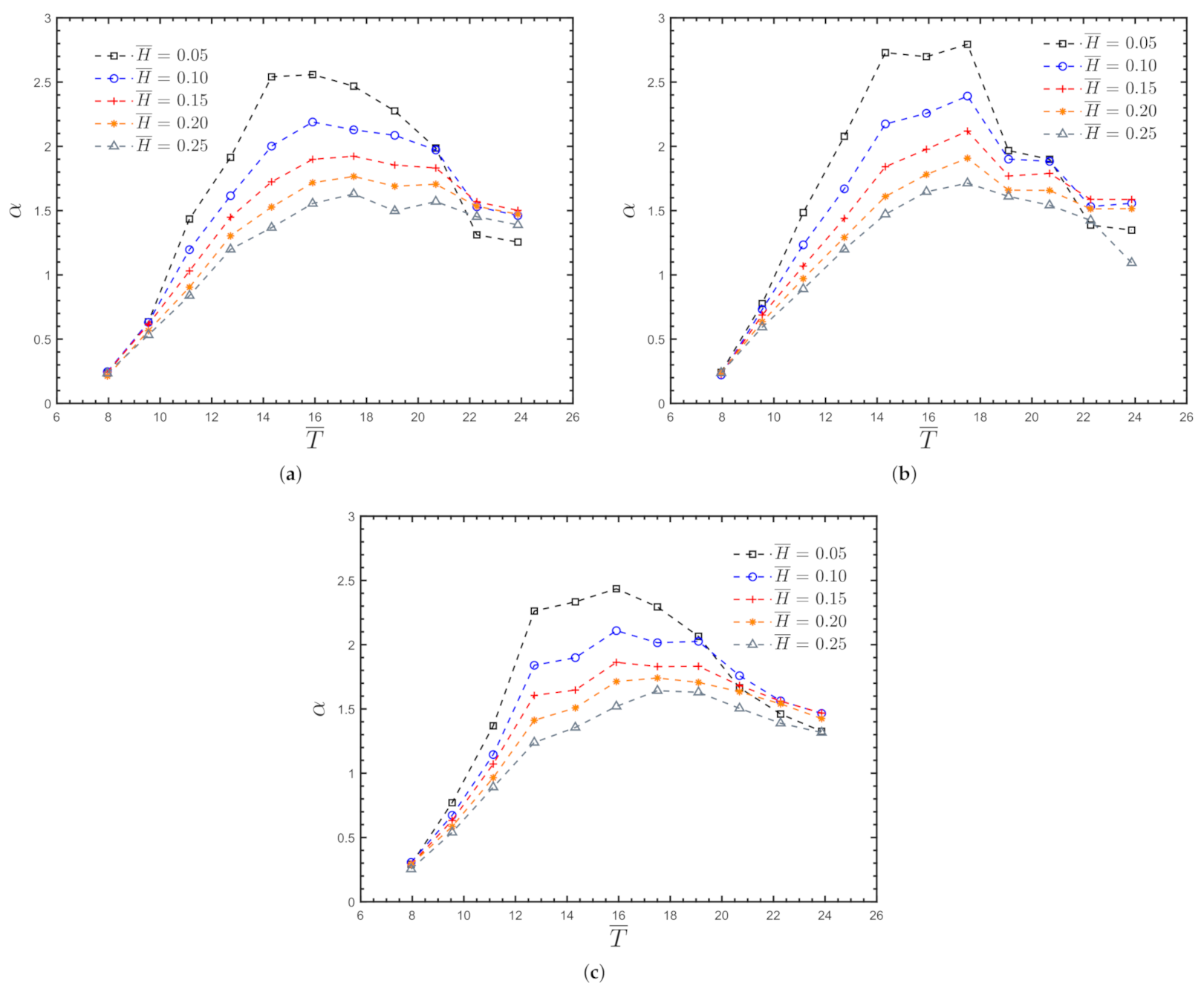
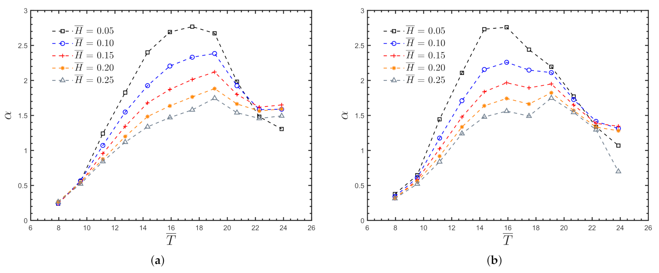
4.1.1. Amplification Factor
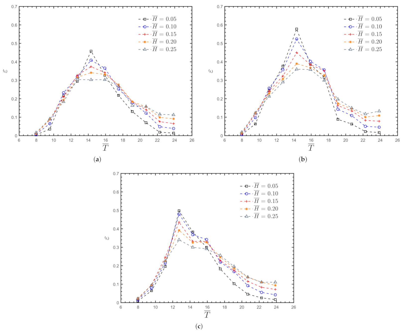
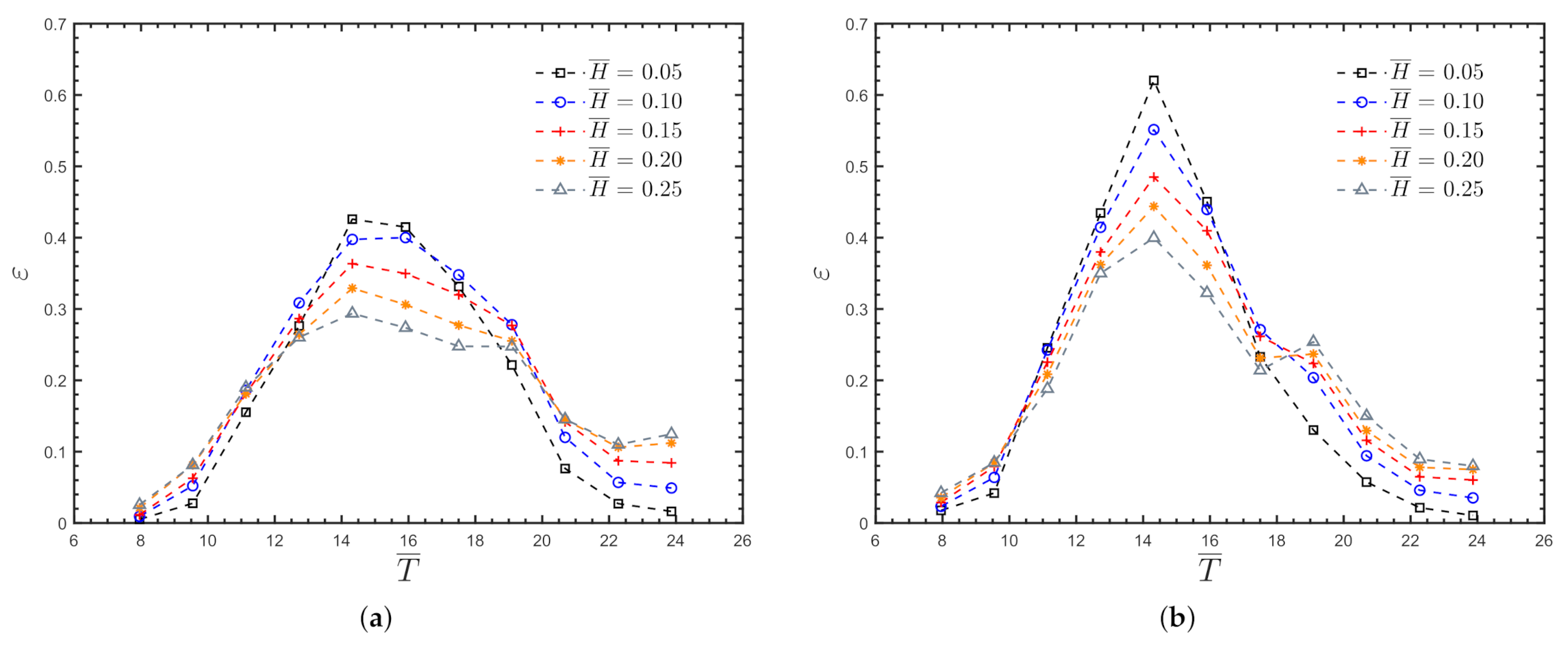
4.1.2. Hydrodynamic Efficiency
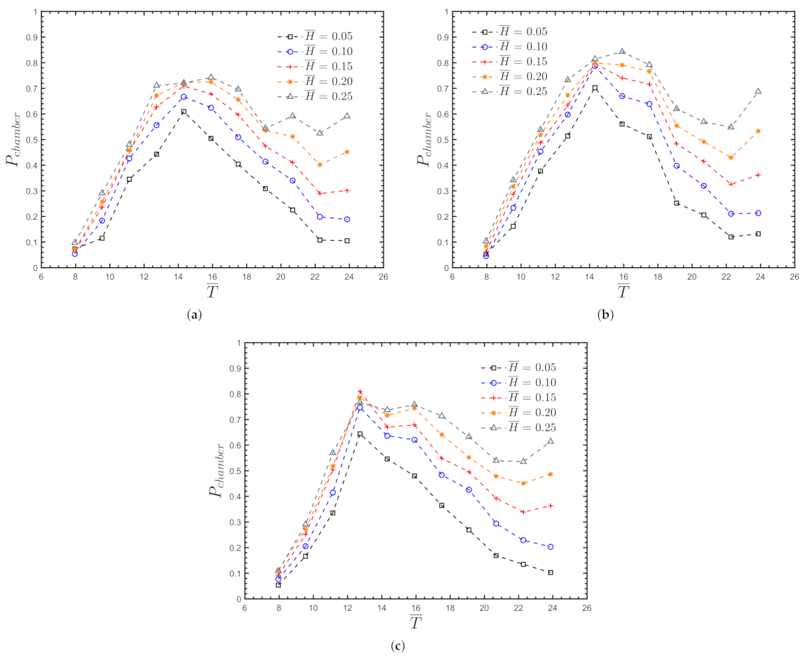
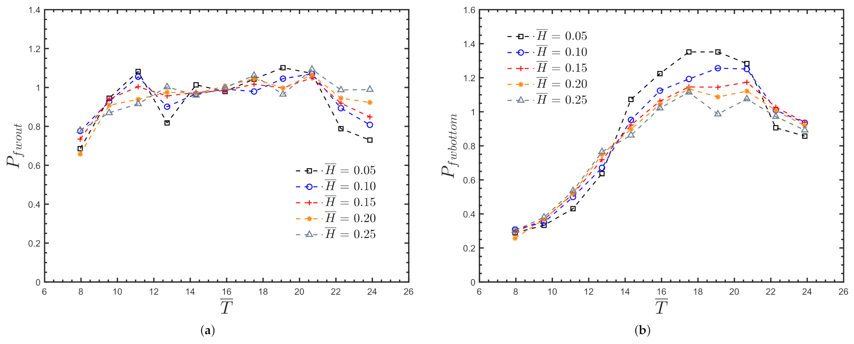
4.1.3. Non-Dimensional Air Pressure
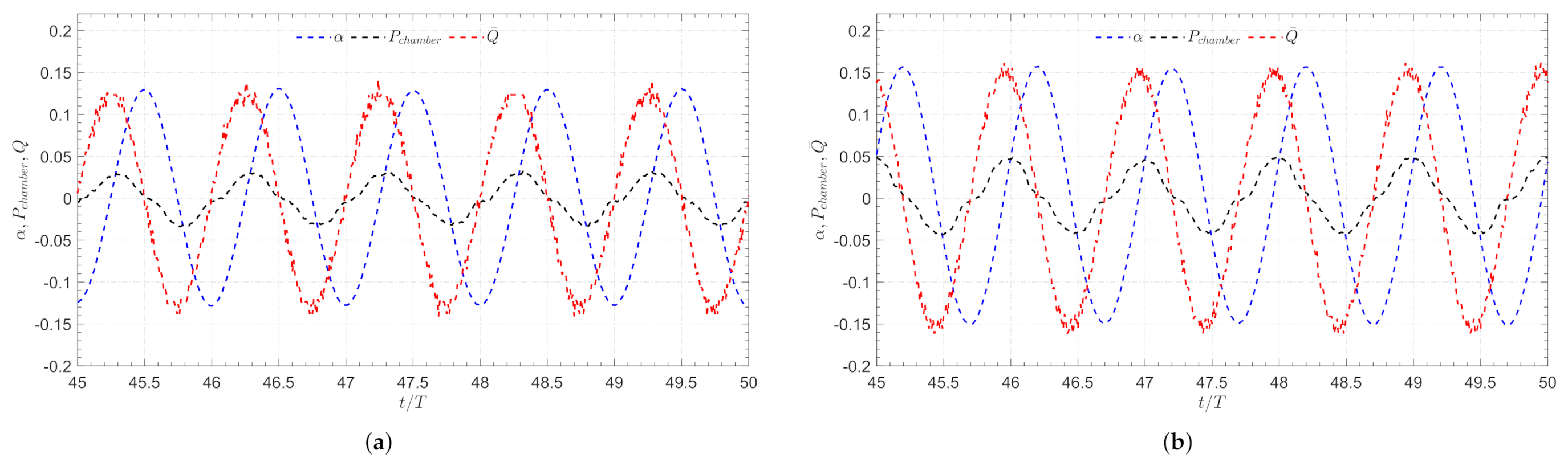
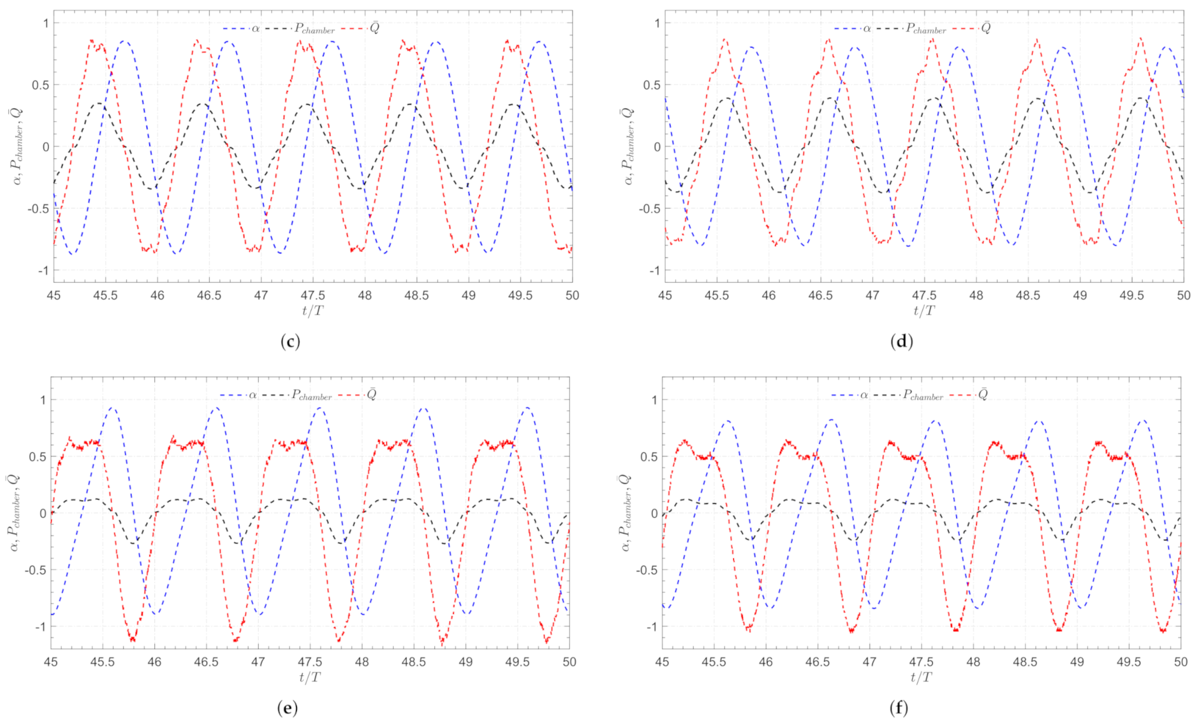
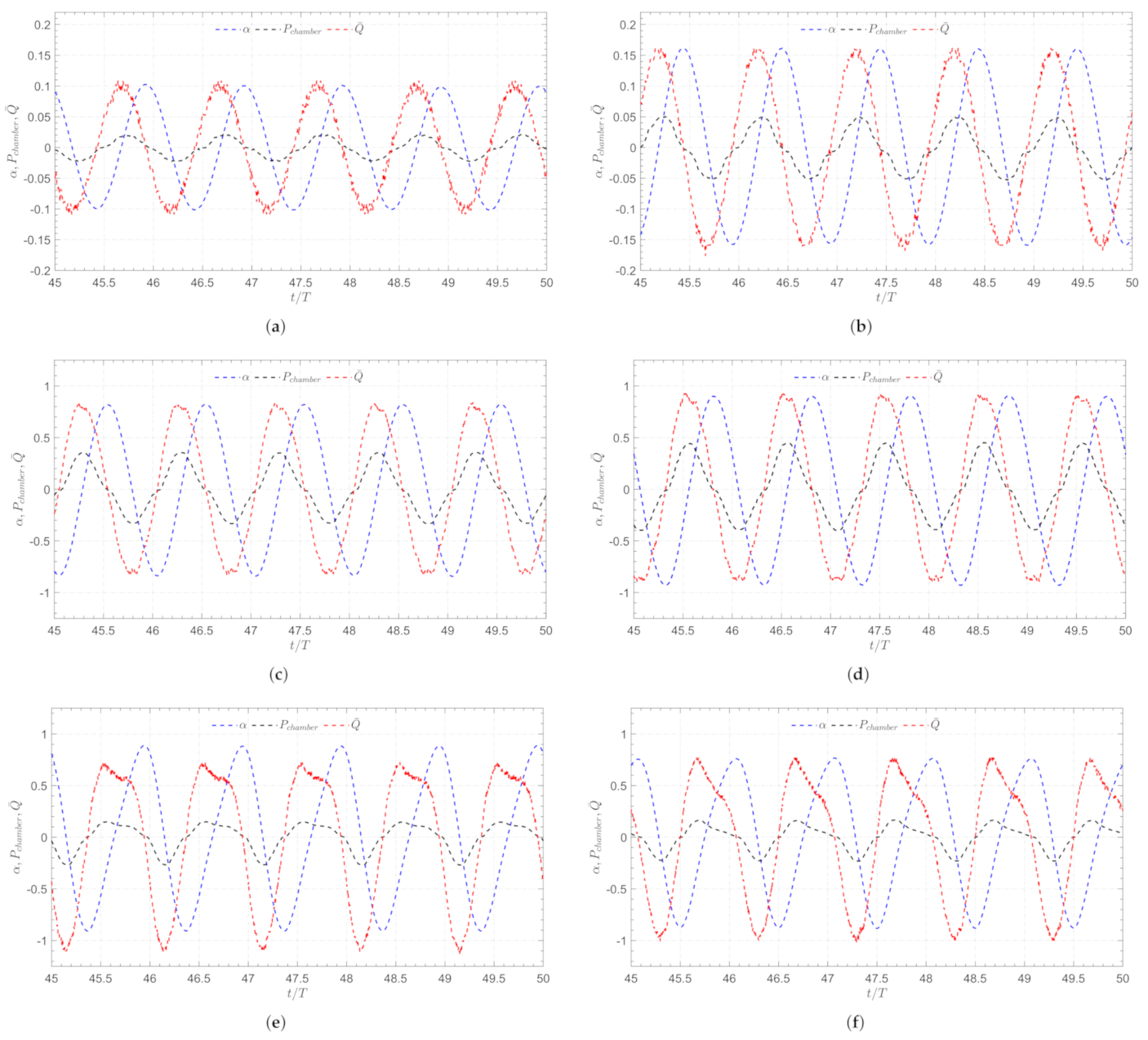
4.1.4. Phase Difference
4.2. Onshore OWC Model
4.2.1. Amplification Factor
4.2.2. Hydrodynamic Efficiency
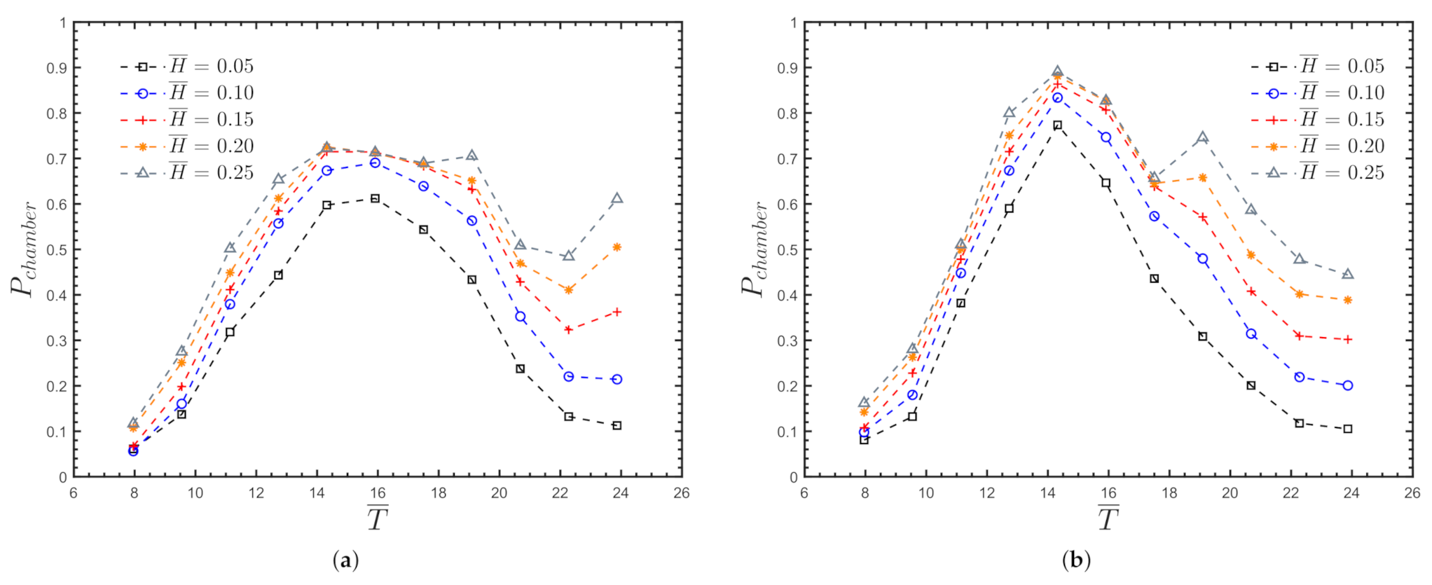
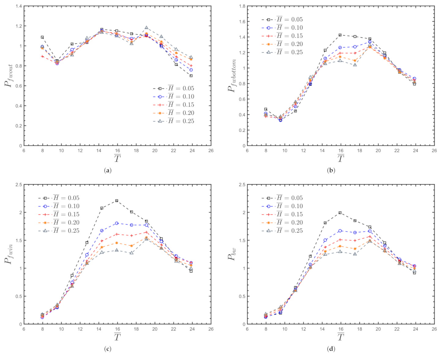
4.2.3. Non-Dimensional Air Pressure
4.2.4. Phase Difference
5. Conclusions
Author Contributions
Funding
Institutional Review Board Statement
Informed Consent Statement
Data Availability Statement
Conflicts of Interest
Appendix A. Water Pressure for the Nearshore OWC Device
Appendix A.1. Non-Dimensional Pressures for θ = 0 °

Appendix A.2. Non-Dimensional Pressures for θ = 15 °
Appendix A.3. Non-Dimensional Pressures for θ = 30 °
Appendix B. Water Pressure for the Onshore OWC Device
Appendix B.1. Non-Dimensional Pressures for θ = 0 °
Appendix B.2. Non-Dimensional Pressures for θ = 15 °

References
- REN21 Renewables Now. Available online: https://www.ren21.net/ (accessed on 26 November 2021).
- Hussain, A.; Arif, S.M.; Aslam, M. Emerging renewable and sustainable energy technologies: State of the art. Renew. Sustain Energy Rev. 2017, 71, 12–28. [Google Scholar] [CrossRef]
- Drew, B.; Plummer, A.R.; Sahinkaya, M.N. A review of wave energy converter technology. Proc. Inst. Mech. Eng. Part A J. Power Energy. 2009, 223, 887–902. [Google Scholar] [CrossRef] [Green Version]
- Titah-Benbouzid, H.; Benbouzid, M. Ocean wave energy extraction: Up-to-date technologies review and evaluation. In Proceedings of the International Power Electronics and Application Conference and Exposition, Shanghai, China, 5–8 November 2014; pp. 338–342. [Google Scholar]
- McCormick, M. Ocean Wave Energy Conversion; Dover Civil and Mechanical Engineering Series; Dover Publications: Mineola, NY, USA, 2007. [Google Scholar]
- Guedes Soares, C.; Bhattacharjee, J.; Tello Ruiz, M.; Pietra, L. Review and classification of wave energy converters. In Maritime Engineering and Technology; CRC Press: Boca Raton, FL, USA, 2012; pp. 585–594. [Google Scholar]
- Falcão, A.F.O. Wave energy utilization: A review of the technologies. Renew. Sustain. Energy Rev. 2010, 14, 899–918. [Google Scholar] [CrossRef]
- Falnes, J. A review of wave-energy extraction. Mar. Struct. 2007, 20, 185–201. [Google Scholar] [CrossRef]
- Clément, A.; McCullen, P.; Falcão, A.; Fiorentino, A.; Gardner, F.; Hammarlund, K.; Lemonis, G.; Lewis, T.; Nielsen, K.; Petroncini, S.; et al. Wave energy in europe: Current status and perspectives. Renew. Sustain. Energy Rev. 2002, 6, 405–431. [Google Scholar] [CrossRef]
- Vicinanza, D.; Di Lauro, E.; Contestabile, P.; Gisonni, C.; Lara, J.L.; Losada, I.J. Review of Innovative Harbor Breakwaters for Wave-Energy Conversion. J. Waterway Port Coast. Ocean Eng. 2019, 145, 03119001. [Google Scholar] [CrossRef]
- Mendoza, E.; Lithgow, D.; Flores, P.; Felix, A.; Simas, T.; Silva, R. A framework to evaluate the environmental impact of ocean energy devices. Renew. Sustain Energy Rev. 2019, 112, 440–449. [Google Scholar]
- Falcão, A.F.O.; Henriques, J.C.C. Oscillating-water-column wave energy converters and air turbines: A review. Renew. Energy 2016, 85, 1391–1424. [Google Scholar] [CrossRef]
- Falcão, A.F.O. First-Generation Wave Power Plants: Current Status and R&D Requirements. In Proceedings of the ASME 22nd International Conference on Offshore Mechanics and Arctic Engineering, Volume 3: Materials Technology, Ocean Engineering, Polar and Arctic Sciences and Technology, Workshops, Cancun, Mexico, 8–13 June 2003; pp. 723–731. [Google Scholar]
- Ibarra-Berastegi, G.; Sáenz, J.; Ulazia, A.; Serras, P.; Esnaola, G.; Garcia-Soto, C. Electricity production, capacity factor, and plant efficiency index at the Mutriku wave farm (2014–2016). Ocean Eng. 2018, 147, 20–29. [Google Scholar] [CrossRef] [Green Version]
- Ning, D.Z.; Wang, R.Q.; Zou, Q.P.; Teng, B. An experimental investigation of hydrodynamics of a fixed OWC Wave Energy Converter. Appl. Energy 2016, 168, 636–648. [Google Scholar] [CrossRef]
- Chen, J.; Wen, H.; Wang, Y.; Ren, B. Experimental investigation of an annular sector owc device incorporated into a dual cylindrical caisson breakwater. Energy 2020, 211, 118681. [Google Scholar] [CrossRef]
- Lighthill, J. Two-dimensional analyses related to wave-energy extraction by submerged resonant ducts. J. Fluid Mech. 1979, 91, 253–317. [Google Scholar] [CrossRef]
- Morris-Thomas, M.T.; Irvin, R.J.; Thiagarajan, K.P. An Investigation Into the Hydrodynamic Efficiency of an Oscillating Water Column. J. Offshore Mech. Arct. 2006, 129, 273–278. [Google Scholar] [CrossRef]
- Torre-Enciso, Y.; Ortubia, I.; López De Aguileta, L.I.; Marqués, J. Mutriku Wave Power Plant: From the Thinking out to the Reality. In Proceedings of the 8th European Wave and Tidal Energy Conference (EWTEC), Uppsala, Sweden, 7–10 September 2009. [Google Scholar]
- Ikoma, T.; Osawa, H.; Masuda, K.; Maeda, H. Expected Values of Wave Power Absorption Around the Japanese Islands Using OWC Types With Projecting Walls. In Proceedings of the ASME 30th International Conference on Ocean, Offshore and Arctic Engineering, Volume 5: Ocean Space Utilization; Ocean Renewable Energy, Rotterdam, The Netherlands, 19–24 June 2011; pp. 573–580. [Google Scholar]
- López, I.; Pereiras, B.; Castro, F.; Iglesias, G. Performance of owc wave energy converters: Influence of turbine damping and tidal variability. Int. J. Energy Res 2015, 39, 472–483. [Google Scholar] [CrossRef]
- John Ashlin, S.; Sannasiraj, S.A.; Sundar, V. Wave Forces on an Oscillating Water Column Device. Procedia Eng. 2015, 116, 1019–1026. [Google Scholar] [CrossRef] [Green Version]
- John Ashlin, S.; Sundar, V.; Sannasiraj, S. Effects of bottom profile of an oscillating water column device on its hydrodynamic characteristics. Renew. Energy 2016, 96, 341–353. [Google Scholar] [CrossRef]
- John Ashlin, S.; Sannasiraj, S.A.; Sundar, V. Hydrodynamic performance of an array of oscillating water colum device exposed to oblique waves. In Proceedings of the 12th International Conference on Hydrodynamics, Egmond aan Zee, The Netherlands, 18–23 September 2016. [Google Scholar]
- Rezanejad, K.; Guedes Soares, C.; López, I.; Carballo, R. Experimental and numerical investigation of the hydrodynamic performance of an oscillating water column wave energy converter. Renew. Energy 2017, 106, 1–16. [Google Scholar] [CrossRef]
- Howe, D.; Nader, J.R. OWC WEC integrated within a breakwater versus isolated: Experimental and numerical theoretical study. Int. J. Mar. Energy 2017, 20, 165–182. [Google Scholar] [CrossRef]
- Ashlin, J.S.; Sannasiraj, S.; Sundar, V. Performance of an array of oscillating water column devices integrated with an offshore detached breakwater. Ocean Eng. 2018, 163, 518–532. [Google Scholar] [CrossRef]
- Rezanejad, K.; Gadelho, J.; Guedes Soares, C. Hydrodynamic analysis of an oscillating water column wave energy converter in the stepped bottom condition using CFD. Renew. Energy 2019, 135, 1241–1259. [Google Scholar] [CrossRef]
- López, I.; Carballo, R.; Taveira-Pinto, F.; Iglesias, G. Sensitivity of owc performance to air compressibility. Renew. Energy 2020, 145, 1334–1347. [Google Scholar] [CrossRef]
- Çelik, A.; Altunkaynak, A. Determination of hydrodynamic parameters of a fixed owc by performing experimental and numerical free decay tests. Ocean Eng. 2020, 204, 106827. [Google Scholar] [CrossRef]
- Chen, J.; Wen, H.; Wang, Y.; Wang, G. A correlation study of optimal chamber width with the relative front wall draught of onshore owc device. Energy 2021, 225, 120307. [Google Scholar] [CrossRef]
- Qiao, D.; Haider, R.; Yan, J.; Ning, D.; Li, B. Review of Wave Energy Converter and Design of Mooring System. Sustainability 2020, 12, 8251. [Google Scholar] [CrossRef]
- Medina-Lopez, E.; Allsop, W.; Dimakopoulos, A.; Bruce, T. Conjectures on the Failure of the OWC Breakwater at Mutriku. In Proceedings of the Coastal Structures and Solutions to Coastal Disasters Joint Conference, Boston, MA, USA, 9–11 September 2015. [Google Scholar]
- Poullikkas, A. Technology prospects of wave power systems. Electron. J. Energy Environ. 2014, 2, 47–69. [Google Scholar]
- Jin, J.; Liu, Z.; Hyun, B.S.; Hong, K. Effects of wave direction on performance of oscillating water column type wave energy convertor. In Proceedings of the International Offshore and Polar Engineering Conference, Rhodes, Greece, 17–22 June 2012; pp. 582–587. [Google Scholar]
- Hughes, S.A. Physical Models and Laboratory Techniques in Coastal Engineering; World Scientific: Singapore, 1993. [Google Scholar]
- Payne, G. Guidance for the Experimental Tank Testing of Wave Energy Converters; SuperGen Marine, University of Strathclyde: Glasgow, UK, 2008. [Google Scholar]
- Weber, J. Representation of non-linear aero-thermodynamic effects during small scale physical modelling of oscillating water column wave energy converters. In Proceedings of the European Wave and Tidal Energy Conference EWTEC, Porto, Portugal, 11–13 September 2007. [Google Scholar]
- Falcão, A.F.O.; Henriques, J.C. Model-prototype similarity of oscillating-water-column wave energy converters. Int. J. Mar. Energy 2014, 6, 18–34. [Google Scholar] [CrossRef]
- Sarmento, A.J.N.A. Model-Test Optimization of an Owc Wave Power Plant. Int. J. Offshore Polar Eng. 1993, 3, ISOPE-93-03-1-066. [Google Scholar]
- Medina Rodríguez, A.A.; Blanco Ilzarbe, J.M.; Silva Casarín, R.; Izquierdo Ereño, U. The Influence of the Chamber Configuration on the Hydrodynamic Efficiency of Oscillating Water Column Devices. J. Mar. Sci. Eng. 2020, 8, 751. [Google Scholar] [CrossRef]
- Medina Rodríguez, A.A.; Silva Casarín, R.; Blanco Ilzarbe, J.M. The influence of oblique waves on the hydrodynamic efficiency of an onshore owc wave energy converter. Renew. Energy 2022, 183, 687–707. [Google Scholar] [CrossRef]
- He, G.; Huang, Z. Using an Oscillating Water Column Structure to Reduce Wave Reflection from a Vertical Wall. J. Waterw. Port Coast. Ocean Eng. 2016, 142, 04015021. [Google Scholar] [CrossRef]
- Iturrioz, A.; Guanche, R.; Lara, J.L.; Vidal, C.; Losada, I.J. Validation of OpenFOAM® for Oscillating Water Column three-dimensional modeling. Ocean Eng. 2015, 107, 222–236. [Google Scholar] [CrossRef]
- Howe, D.; Nader, J.R.; Macfarlane, G. Experimental investigation of multiple Oscillating Water Column Wave Energy Converters integrated in a floating breakwater: Energy extraction performance. Appl. Ocean Res. 2020, 97, 102086. [Google Scholar] [CrossRef]
- Ning, D.Z.; Shi, J.; Zou, Q.P.; Teng, B. Investigation of hydrodynamic performance of an OWC (oscillating water column) wave energy device using a fully nonlinear HOBEM (higher-order boundary element method). Energy 2015, 83, 177–188. [Google Scholar] [CrossRef]
- Kamath, A.; Bihs, H.; Arntsen, Ø.A. Numerical investigations of the hydrodynamics of an oscillating water column device. Ocean Eng. 2015, 102, 40–50. [Google Scholar] [CrossRef] [Green Version]


| Parameter | Value or Range |
|---|---|
| Water depth (h) | 0.4 m |
| Incident wave height (H) | 0.02–0.10 m at 0.02 m interval |
| Wave period (T) | 1.0–3.0 s at 0.2 s interval |
| Wave length () | 1.464, 1.936, 2.393, 2.836, 3.269, 3.695, 4.115, 4.532, 4.945, 5.356 and 5.765 m |
| Model length | 0.155 m |
| Model width | 0.255 m |
| Model height | 0.655 m |
| Model draft | 0.260 m |
| Model front wall thickness | 0.333 m |
| Gap length | 0.128 m |
| Parameter | Value or Range |
|---|---|
| Relative wave height | 0.05, 0.10, 0.15, 0.20 and 0.25 |
| Relative wave period | 7.956, 9.547, 11.138, 12.729, 14.320, 15.911, 17.502, 19.093, 20.684, 22.275 and 23.867 |
Publisher’s Note: MDPI stays neutral with regard to jurisdictional claims in published maps and institutional affiliations. |
© 2022 by the authors. Licensee MDPI, Basel, Switzerland. This article is an open access article distributed under the terms and conditions of the Creative Commons Attribution (CC BY) license (https://creativecommons.org/licenses/by/4.0/).
Share and Cite
Medina Rodríguez, A.A.; Posada Vanegas, G.; Silva Casarín, R.; Mendoza Baldwin, E.G.; Vega Serratos, B.E.; Puc Cutz, F.E.; Mangas Che, E.A. Experimental Investigation of the Hydrodynamic Performance of Land-Fixed Nearshore and Onshore Oscillating Water Column Systems with a Thick Front Wall. Energies 2022, 15, 2364. https://doi.org/10.3390/en15072364
Medina Rodríguez AA, Posada Vanegas G, Silva Casarín R, Mendoza Baldwin EG, Vega Serratos BE, Puc Cutz FE, Mangas Che EA. Experimental Investigation of the Hydrodynamic Performance of Land-Fixed Nearshore and Onshore Oscillating Water Column Systems with a Thick Front Wall. Energies. 2022; 15(7):2364. https://doi.org/10.3390/en15072364
Chicago/Turabian StyleMedina Rodríguez, Ayrton Alfonso, Gregorio Posada Vanegas, Rodolfo Silva Casarín, Edgar Gerardo Mendoza Baldwin, Beatriz Edith Vega Serratos, Felipe Ernesto Puc Cutz, and Enrique Alejandro Mangas Che. 2022. "Experimental Investigation of the Hydrodynamic Performance of Land-Fixed Nearshore and Onshore Oscillating Water Column Systems with a Thick Front Wall" Energies 15, no. 7: 2364. https://doi.org/10.3390/en15072364
APA StyleMedina Rodríguez, A. A., Posada Vanegas, G., Silva Casarín, R., Mendoza Baldwin, E. G., Vega Serratos, B. E., Puc Cutz, F. E., & Mangas Che, E. A. (2022). Experimental Investigation of the Hydrodynamic Performance of Land-Fixed Nearshore and Onshore Oscillating Water Column Systems with a Thick Front Wall. Energies, 15(7), 2364. https://doi.org/10.3390/en15072364