Abstract
A distributed parameter model was developed for an evaporation system in a 35 MW natural circulation pulverized-coal oxy-fuel combustion boiler, which was based on a computational fluid dynamic simulation and in situ operation monitoring. A mathematical model was used to consider the uneven distribution of working fluid properties and the heat load in a furnace to predict the heat flux of a water wall and the wall surface temperature corresponding to various working conditions. The results showed that the average heat flux near the burner area in the air-firing condition, the oxy-fuel combustion with dry flue gas recycling (FGR) condition, and the oxy-fuel combustion with wet flue-gas recycle condition were 168.18, 154.65, and 170.68 kW/m2 at a load of 80%. The temperature and the heat flux distributions in the air-firing and the oxy-fuel combustion with wet FGR were similar, but both were higher than those in the oxygen-enriched combustion conditions with the dry FGR under the same load. This study demonstrated that the average metal surface temperature in the front wall during the oxy-fuel combustion condition was 3.23 °C lower than that under the air-firing condition. The heat release rate from the furnace and the vaporization system should be coordinated at a low and middle load level. The superheating surfaces should be adjusted to match the rising temperature of the flue gas while shifting the operation from air to oxy-fuel combustion, where the distributed parameter analytical approach could then be applied to reveal the tendencies for these various combustion conditions. The research provided a type of guidance for the design and operation of the oxy-fuel combustion boiler.
1. Introduction
Oxy-fuel combustion is a promising power production technology being actively investigated [1]. This operation method could lead to retrofitting of the existing pulverized-coal combustion power plant boiler, based on flue gas recirculation and pure oxygen injection rather than using air. The medium flow and heat transfer characteristics in the furnace should be regulated by flue gas recycling (FGR) in order to obtain a higher CO2 concentration. This technique could be easily implemented for large-scale emission reductions of CO2, due to the reduced flue gas exhaust and the significant heat loss reduction, especially in the context of carbon neutralization.
Pulverized coal combustion in ordinary air and CO2 atmospheric conditions differ in their heat and mass transfer characteristics. The furnace heat exchange is dependent on the flame temperature, flue gas composition, particle composition, and radiation absorption rate between the water wall temperature and the interior flow field of the furnace. The radiation heat transfer in the furnace primarily occurs through CO2, moisture, char, soot, and ash. The flue gas and the heat transfer law in the design and operation of the boiler focus on exploring the radiation characteristics of oxy-fuel combustion. Guo et al. [2] constructed a 200 MW tangential pulverized-coal boiler numerical simulation with oxy-fuel and air combustion conditions to show the radiation characteristics of these fluid properties and compositions. The gray and non-gray radiation models over various performances have been adopted to obtain the characteristics of heat transfer, the temperature distribution in the furnace, and the composition of exhaust gas in air-firing and oxygen-enriched wet/dry FGR conditions [3]. Black et al. investigated the difference in heat transfer between the air and the oxy-fuel combustion environment within a 500 MW pulverized-coal power plant boiler [4], where the radiation heat transfer over various concentrations of the oxy-fuel combustion conditions were analyzed. Gani et al. [5] carried out a modeling study on coal combustion in air and oxy-fuel mode by using Fluent, a CFD tool, and investigated the effects of balance gas N2 and CO2 and the effects of oxygen concentration on coal burning. Ahn et al. [6] studied the heat transfer and gas radiation characteristics in a 0.5 MW class oxy-fuel boiler under different loads with or without FGR. The natural circulation boiler furnace water wall was the primary heat-absorbing surface, where the fire-facing side was the radiant endothermic process, and a specific velocity of hot water and steam flowed inside the water wall. The evaporator was the worst within the operating equipment. The working fluid status was fickle in the part. De Kerret et al. [7] proposed a new methodology based on the understanding of key contributions to vertical two-phase flow pattern maps in tube bundles, leading to a more complete flow pattern map. The different two-phase flow patterns can be bubbly, intermittent, or annular. The heat transfer mode of the working fluid varies along the tube length corresponding to the different flow patterns. Guzella et al. [8] put forward two-dimensional simulations of nucleation, growth and departure of bubbles and boiling heat transfer at different reduced temperatures. Weise et al. described the heat transfer coefficient during flow boiling in horizontal tubes with circumferentially varying heat flux [9], adapting flow-pattern-based heat transfer models using local heat flux. The model of a gas–liquid two-phase flow in a helically coiled tube was established by Wu et al. [10] based on the separated phase flow model. The model can be used to solve gas-film velocity, gas-film thickness and heat transfer coefficient, and predict gas–liquid two-phase boiling heat transfer in helically coiled tubes. Studying the working fluid and the heat transfer in the heat exchanger of oxy-fuel combustion boilers is important when reducing the flow resistance, preventing the deterioration of heat transfer, and avoiding the unstable working medium flow of the heat-absorbing surface.
Boiler evaporation system modeling is generally constructed by the following three methods: the lumped parameter model, the linear and nonlinear parameter model, and the distributed parameter model [11]. The lumped parameter model is a model established under a simplified assumption that the state parameters of the medium in the heating pipes are uniform. Then, a representative point is selected in space, and the medium parameters of the point are used as the lumped parameters of the link. The distributed parameter model can fully reflect the linear/nonlinear distributed parameter characteristics of thermal objects and can also accurately reflect the variation law of metal wall temperature. Li et al. [12] improved the traditional thermodynamic method, where the evaporator heat-absorbing surface was divided into the preheater, the evaporator, and the superheater. The established model could conduct static and dynamic simulation analyses. Yu et al. [13] established a lumped-parameter model for natural circulation drum-boilers to calculate the heat flux transferred into water wall tubes, which can be used to describe the complicated dynamics of the entire evaporation system. Laubscher et al. [14] proposed a computational fluid dynamics modeling methodology used to evaluate the thermal performance of the water wall evaporator, the platen, and the final stage superheaters of a subcritical pulverized coal-fired boiler at full and reduced boiler loads. Tang et al. [15] developed a thermal–hydraulic model for the evaporator system of a 660 MWe ultra-supercritical CFB boiler. Pressure drop, mass flux distribution and metal temperature in the evaporator system were estimated. Chu et al. [16] proposed a 2D accurate, distributed parameter model for the evaporation system of a controlled natural circulation boiler, based on the 3D temperature distribution and the emissivity of the particle phase. The evaporation system is divided into a subcooled region, a boiling region, and a super-heated region, according to the secondary water/steam status. The boundaries of these regions are movable. The steam–water separation takes place at the dryout location in the evaporating tubes. Zheng et al. [17] presented the distributed parameter model for the evaporation system based on 3D combustion monitoring in the furnace. The mathematical model was formulated to predict the transient distribution of the parameters, such as heat flux, the metal surface temperature, and steam quality. A distributed parameter model was built in a supercritical W-shaped once-through boiler, which accounted for the non-uniform distributions of the surface heat transfer and the frictional resistance coefficient [18]. The heat transfer characteristics of the W-shaped water wall at the near-critical and supercritical pressures were analyzed. Laubscher et al. [19,20] developed a computational fluid dynamics model and a steady-state 1D computer model, simulating the heat transfer in the evaporation system of grate-fired biomass boilers. Many scholars have carried out evaporation system modeling research studies on various types of boilers, but there are relatively few studies on the heating surfaces of oxy-fuel combustion boilers. At the same time, most of the studies above were based on boiler side mechanisms and lack of furnace side combustion information.
In this paper, a medium temperature and medium pressure natural circulation air/oxy-fuel combustion boiler was investigated. The conventional air-firing and oxy-fuel combustion boiler was simulated numerically under various load conditions by using Fluent to establish a distribution parameter model on the wall temperature and heat flux. This demonstration unit was proven to be an effective strategy for the design, operation, and combustion diagnosis of an oxy-fuel combustion boiler.
2. Materials and Methods
2.1. Numerical Simulation of Oxy-Fuel Combustion Boiler
The boiler was a pulverized-coal combustion unit single-furnace, with a slightly positive pressure, a π-type arrangement, and swirl burners mounted on the front wall. The steam mass flow rate was 38 t/h, the main steam pressure was 4.3 MPa, and the feed water temperature was 105 °C. The structure of the boiler and the thermodynamic system diagram are shown in Figure 1.

Figure 1.
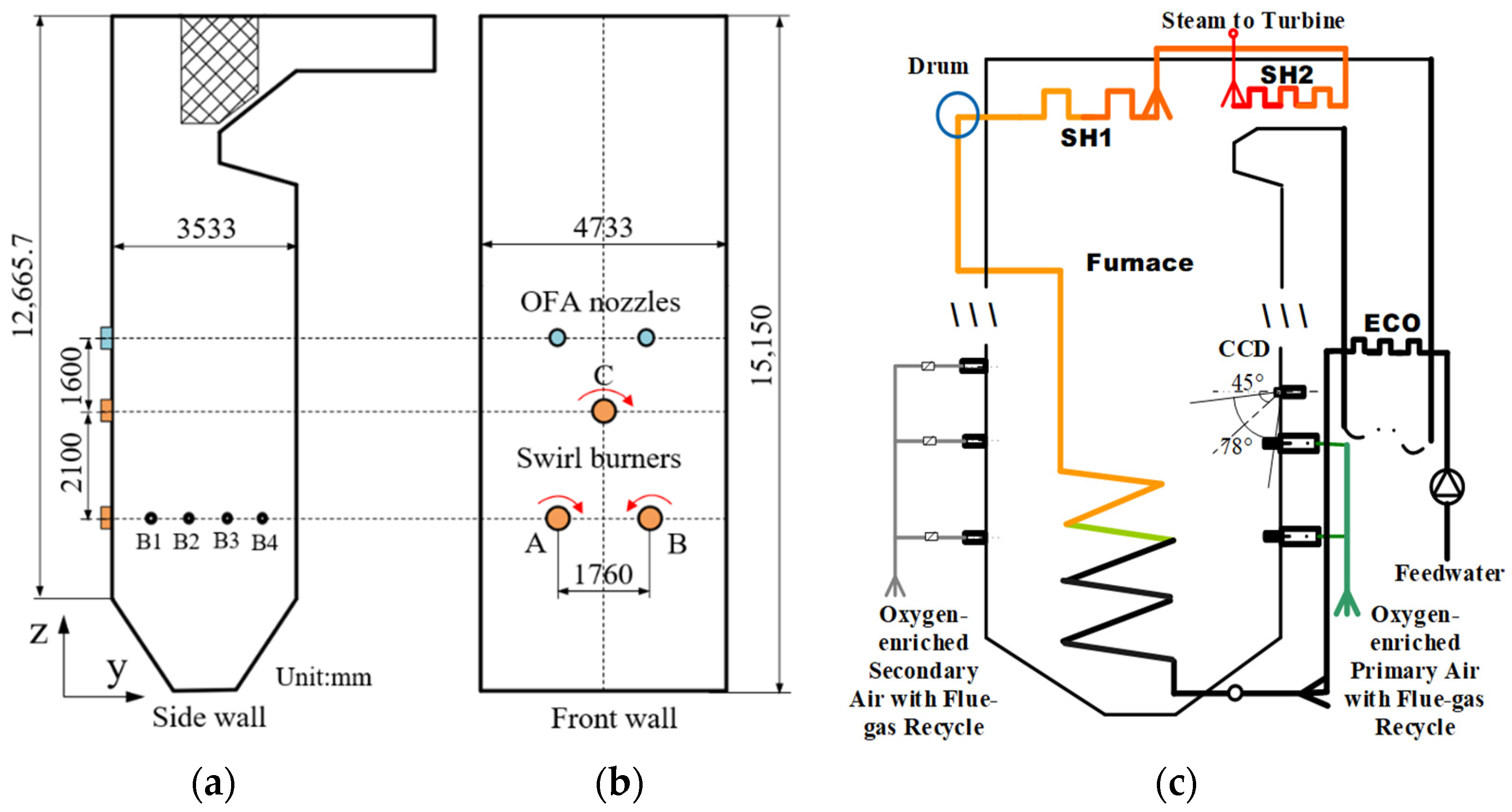
Structure of the boiler: (a) z–y plane of the furnace, (b) z–x plane of the furnace, and the thermodynamic system diagram (c). OFA nozzles: over-fire air nozzles; SH1, 2: 1-stage superheater, 2-stage superheater; CCD: charge-coupled device; ECO: economizer.
As a part of our work on oxy-fuel combustion [21], the cross-section of the boiler was 4733 mm wide, 3533 mm deep, and 15,150 mm tall. The designed chamber volume heating load was 163.3 kW/m3 and the cross-section heating load was 1.993 MW/m2. The front wall was arranged to have three swirl burners in a triangular shape. B1–B4 (Figure 1a) are four measurement openings arranged symmetrically for measuring the temperature and heat flux. The whole furnace was composed of the entire steel framework and the suspension structure.
The oxy-fuel combustion system included the swirl burner, the over-fire air, the oxygen injectors, and the auxiliary equipment. The staged air/flue gas was used for combustion-supporting organization of the flow field, which ensured the stability of the coal combustion. Pure oxygen should be mixed previously with flue gas as the primary air and then conveyed with pulverized-coal into the furnace via burners. Table 1 shows the proximate and the ultimate analysis of coal. The coal had low sulfur, high ash content and was easily ignited. The inlet flow rates of the air/flue gas at all stages under different working conditions are shown in Table 2.

Table 1.
Proximate and ultimate analyses of the coal.
Table 2.
Velocity of the flow rates at the inlet of the boiler.
2.2. Distributed Mathematical Model
The natural circulation oxy-fuel combustion boiler had 4 common down-comers, 28 connecting pipes, 202 rising water wall tubes, and 28 steam-water leading pipes. The boiler water wall was designed with a 12-water circulation circuit. The evaporation zone between the ash hopper (6.33 m) and the furnace arch (15.33 m) was divided into 18 layers. The horizontal cross-section was uniformly divided into 10 × 10 grids. There were 720 surface meshes in total.
The inner water wall heat flux adopted the average surface temperature of the inner tube wall, and the flue gas model adopted the temperature outside the fire-facing tube wall. The water/steam model considered the inner wall temperature as the input for calculating the working fluid enthalpy, whereas the external wall temperature was used to validate the model and evaluate the safe operation of the boiler. Neither the average temperature of the inner wall nor that of the outer wall can be used as the lumped parameter to meet the requirements at the same time. Therefore, a dynamic lumped model with the average temperature of the inner wall of the tube as the lumped parameter combined with a steady-state two-dimensional heat conduction model that can reflect the temperature of the outer wall of the tube was adopted. The lump-parameter model is:
The two-dimensional steady-state heat conduction model is:
The dynamic model of the water/steam in the risers, coupled with mass, momentum, and energy conservation equations is shown as:
The single-phase water pressure variations under subcritical conditions and the surface heat transfer coefficient α were calculated with the Dittuse–Boelter correlation [17]:
The vapor–liquid two-phase flow expressing the correlation of heat transfer coefficient between the two-phase flow and liquid is [17]:
3. Results and Discussion
The in situ operating conditions were performed to verify the results from the air and oxy-fuel combustion boiler. Table 3 shows the typical cases during the mode transition of the study.
Table 3.
Operation parameters during the mode transition.
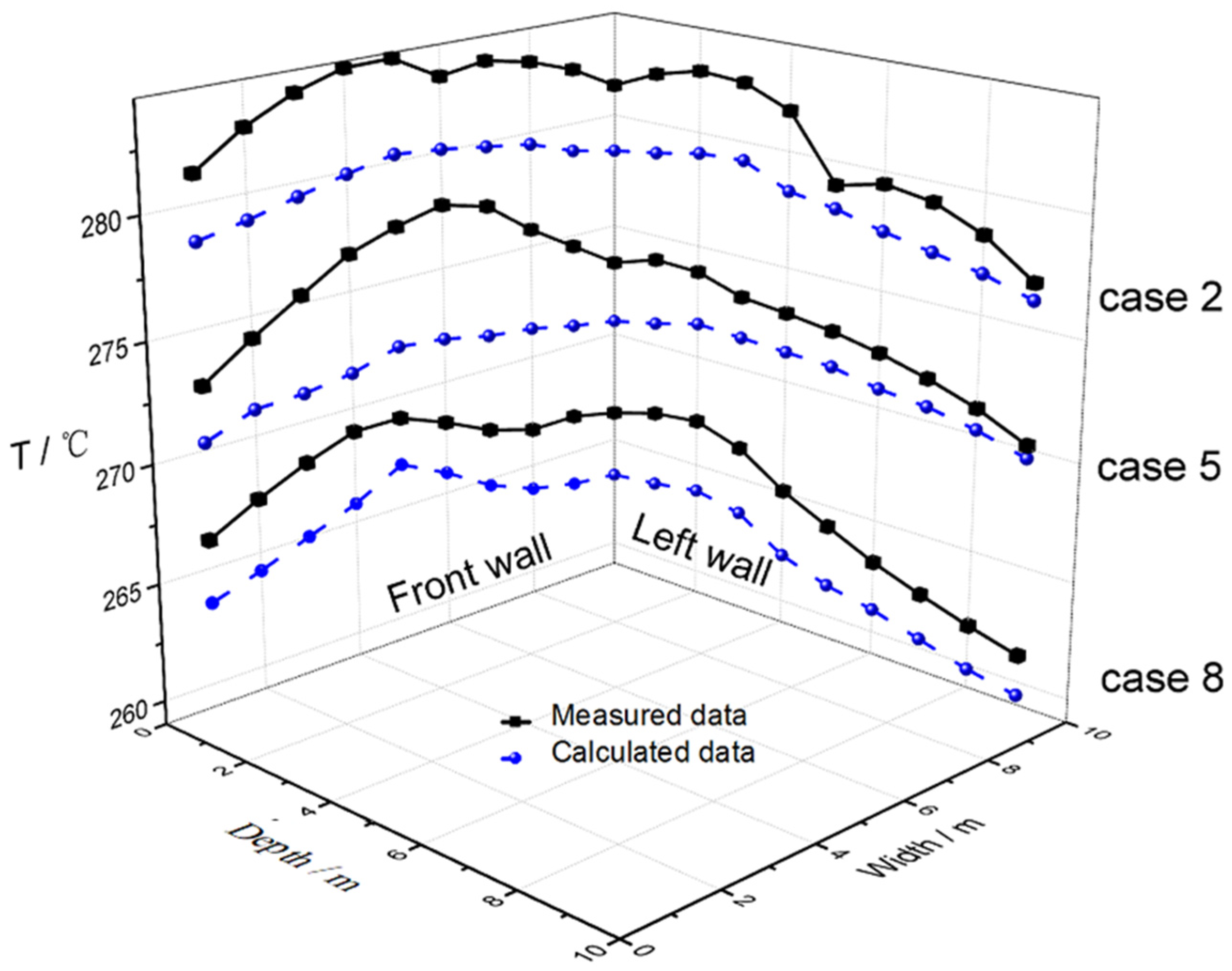
Figure 2 shows the online measurement of the external wall temperatures and the simulation results at 60%, 80%, and 100% load rates during the dry FGR oxy-fuel combustion at a height of 11.5 m. The maximum temperature relative error in case 5 was 2.14% at a width of 2.58 m. The wall temperature rose as the load increased, and the metal wall temperature in the middle of the front wall was higher than that on both sides, due to the arrangement of the swirl burners. The tube wall temperature predicted by the mathematical model was in agreement with that in the in situ operation. The highest temperature of the front wall was higher than that of the left, and the average temperature of the left wall close to the front was higher than that near the rear wall. The swirl burners were installed on the front wall in a triangular configuration; thus, the heat flux of the front wall was higher, corresponding to the higher wall metal surface temperature.
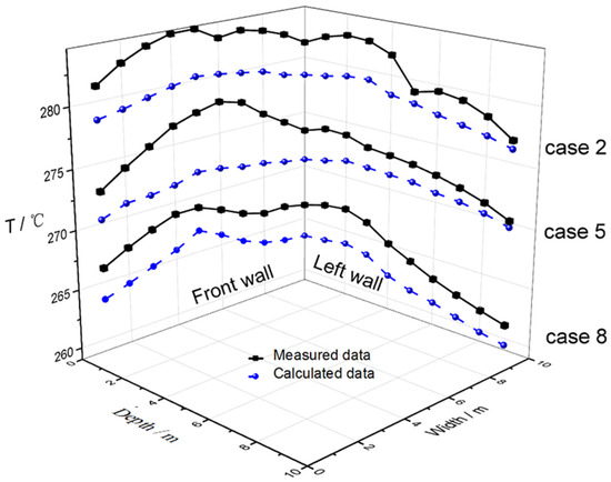
Figure 2.
Comparison of temperatures on the front and left wall in case 2, case 5, and case 8.
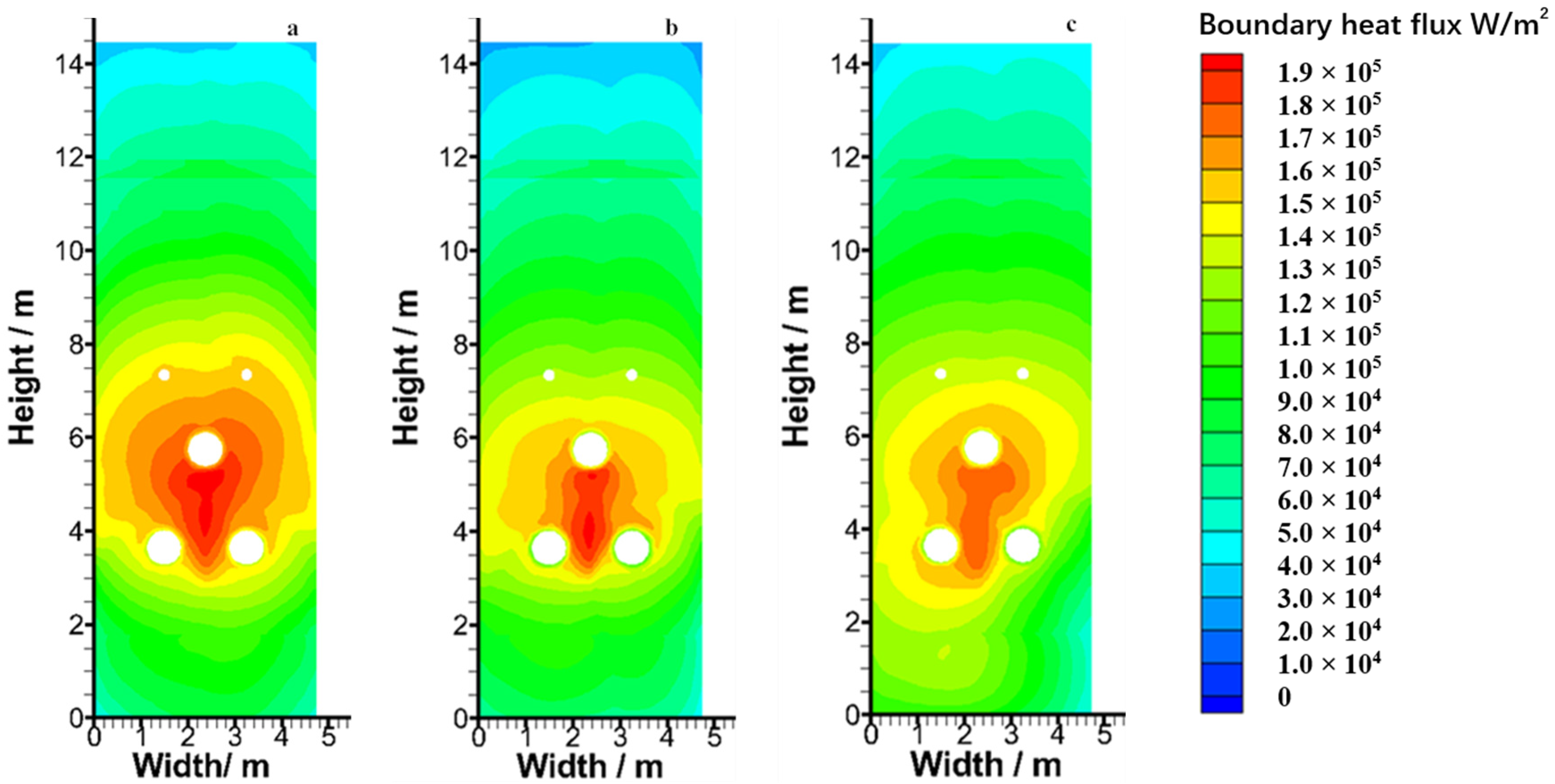
Figure 3 and Figure 4 depict heat flux distributions on the front water wall and the metal wall temperature on the rear water wall under three different combustion conditions with a 100% load. The heat flux in the air-firing condition was more non-uniform than that in the oxy-fuel dry/wet FGR conditions at the 100% load. The front wall heat flux in the air-firing condition was more uneven than in the other two oxy-fuel combustions. The wall heat flux in the dry FGR condition was well distributed, due to the three atomic gases (CO2 and H2O) present in the specific heats, diffusion coefficients, and radiation characteristics. The wall heat flux in the wet FGR oxy-fuel condition was higher than that in the dry FGR oxy-fuel condition on account of the higher gas emission rate and temperature.
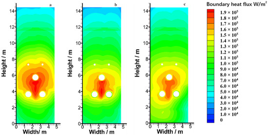
Figure 3.
Distributions of heat flux in the front wall: (a) case 7, (b) case 8; and (c) case 9.
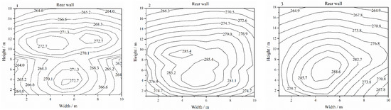
Figure 4.
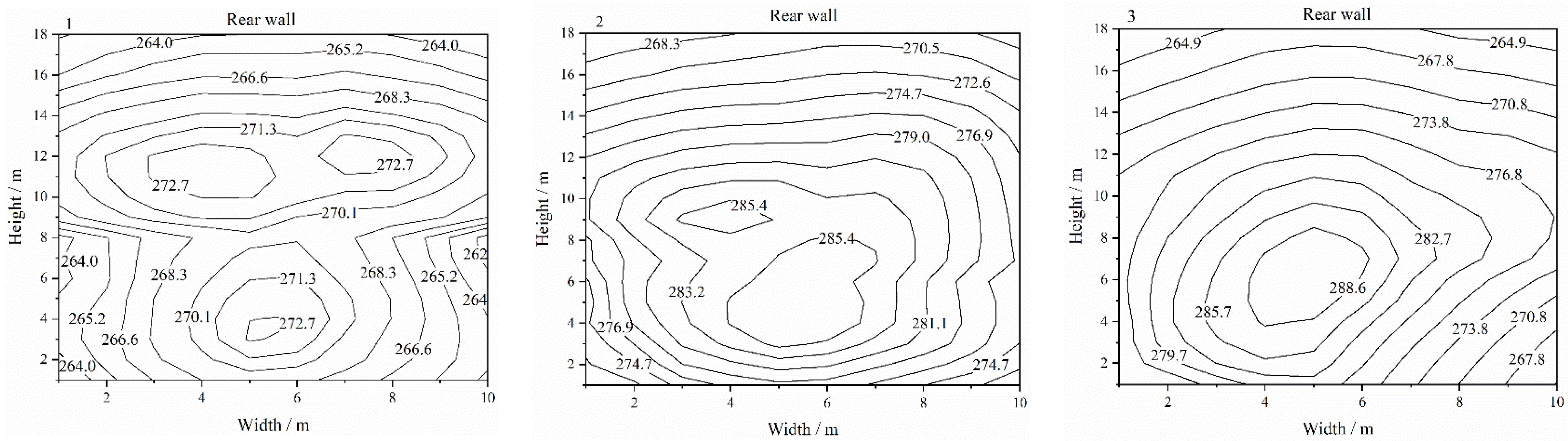
Distributions of the metal temperature (°C) on the rear wall: (1) case 7, (2) case 8, and (3) case 9.
As shown in Figure 4, the distributions of the metal wall temperature on the rear water wall had similar tendencies with the heat flux distributions under the same combustion conditions. There was a high temperature region near the central position with symmetrical arrangement of the swirl burners, and the high temperature flue gas aggregated in the combustion area. The wall temperature in the air-firing, oxy-fuel dry/wet FGR conditions showed that the metal temperature was consistent with the uneven wall heat flux during the mode transition. The temperature difference of the front wall under the air-firing condition was 7.37 °C higher than that under the oxy-fuel wet FGR condition. The metal wall temperature distribution in the oxy-fuel dry/wet FGR condition was more uniform than that in the air-firing condition at the same load, which was consistent with the result that the wall heat flux distribution was more uniform under the oxy-fuel condition than under the air condition.
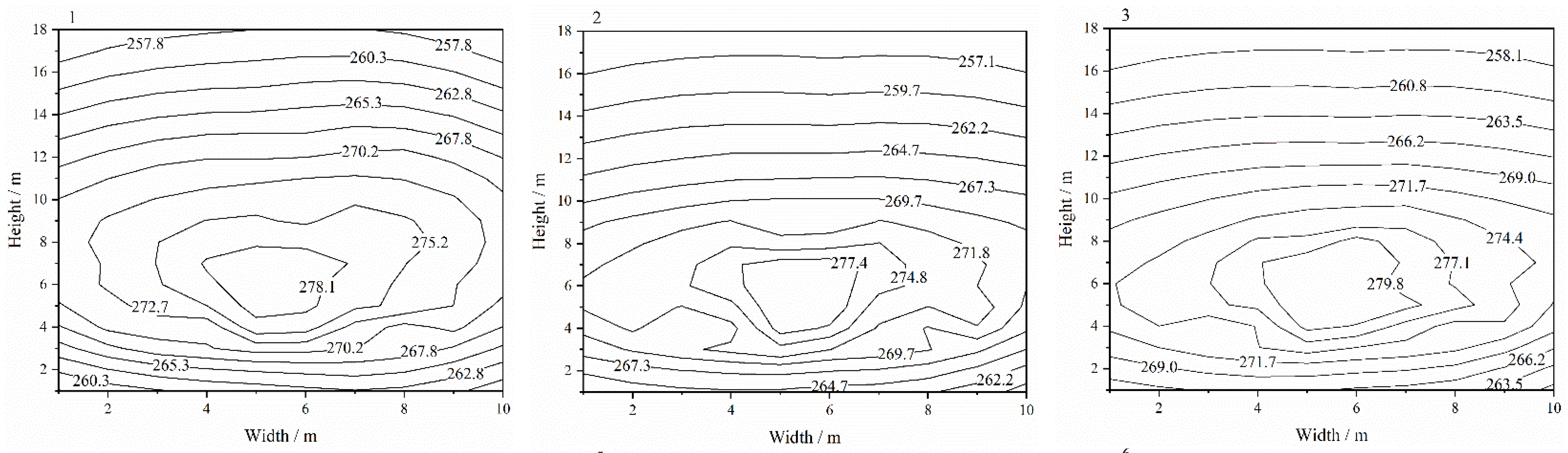
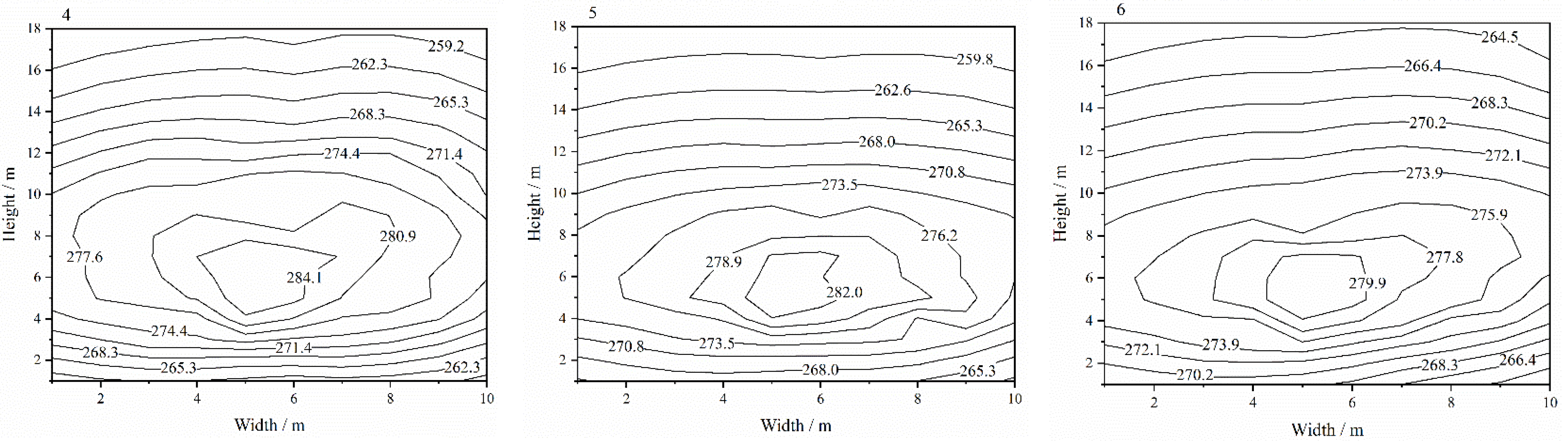
Figure 5 shows the metal temperature distribution on the front water wall, which was similar to the distribution of heat flux in the corresponding cases. The highest water wall temperature in the oxy-fuel dry/wet FGR condition was lower than that in the air-firing condition. It can also be found that when the load rose from 60% to 80%, the wall temperature rose. This is because when the load increased, the corresponding wall heat flux grew, and the wall temperature grew. The oxy-fuel dry/wet FGR water wall temperature and heat flux varied with the in situ operation conditions, which means the model can produce correct predictions.
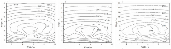
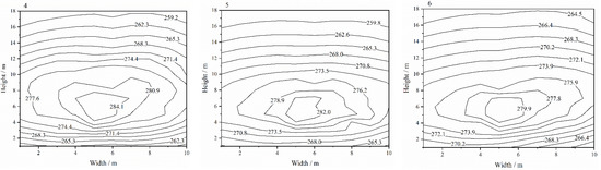
Figure 5.
Distributions of metal temperature (°C) on the front wall. 1–3: case 1–case 3, 4–6: case 4–case 6.
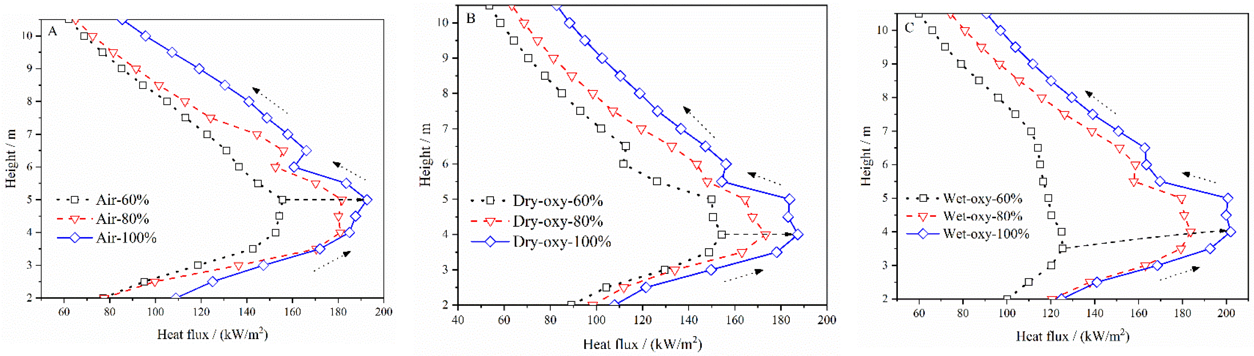
Figure 6 illustrates the variation at a specific location of the boiler. The heat flux rose with the height increment, reached its maximum at 4 to 5 m, and then decreased with the increase in height. This maximum position was slightly over the burner combustion region. The pulverized-coal was mixed with the secondary air at the center of the three-swirl burner region; thus, the flue gas temperature was relatively higher, and the radiant heat flux was the highest. The flue gas temperature and the heat flux decreased with the rising height. The highest heat fluxes in the air-firing and the oxy-fuel wet FGR conditions were significantly higher than that in the oxy-fuel dry FGR condition at the same load. The maximum heat fluxes in the three cases were 192.6, 187.3, and 201.8 kW/m2 at 100% load. The wall heat flux in the oxy-fuel dry FGR condition near the burner region increased more smoothly than that in the other two working conditions at the same load. The heat flux had a smooth change in the variable operation conditions.
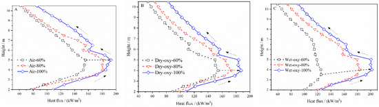
Figure 6.
Heat flux distributions at 2.36 m wide at the three typical loads in air-firing (A), dry FGR (B), and wet FGR (C) conditions.
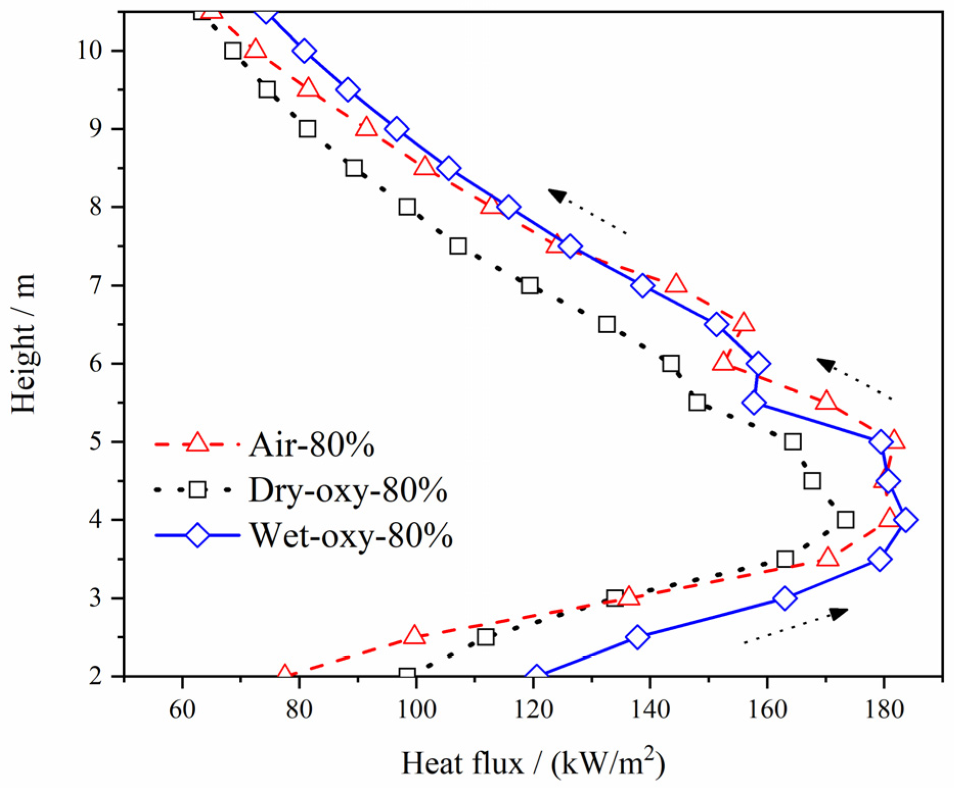
The oxy-fuel dry FGR heat flux in the burner region was significantly lower than the other two conditions at 80% load, as seen in Figure 7. The front wall average heat flux and metal temperature are illustrated in Table 4. The wall heat flux in the oxy-fuel dry FGR condition varied with the changing load. When the load rose from 60% to 80%, and then from 80% to 100%, the oxy-fuel dry FGR condition wall heat flux increased by 14.054 and 14.586 kW/m2, the relative change rate of the average wall heat flux was 1.038, and the relative change rates of the average wall heat flux in air-firing and oxy-fuel wet FGR conditions were 1.455 and 1.477. These values were higher than that in the oxy-fuel dry FGR condition (1.038).

Figure 7.
Heat flux distributions at the width of 2.36 m at 80% load in various combustion environments.
Table 4.
Comparison of the average heat flux and temperature of the front wall in different cases.
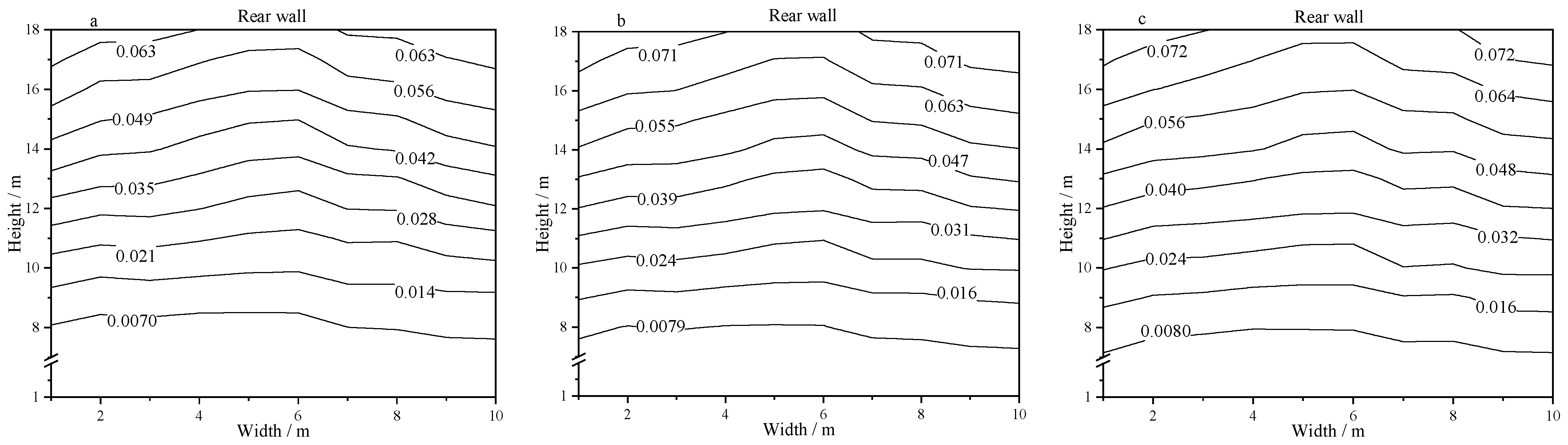
Figure 8 illustrates the steam quality distribution on the rear wall in the three different combustion environments at 100% load. The steam quality under the three different combustion modes showed that the middle value was higher than both sides at the same height, due to the high density of the heat flux in the middle area of the furnace. The water wall steam quality distribution in the dry FGR oxy-fuel condition was more uniform than that in the air-firing condition under the same load. The outlet steam quality of the rear wall in the air-firing condition was 0.063. The heating surface should be rearranged taking into account both the air-firing and the oxy-fuel combustion in the boiler.
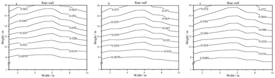
Figure 8.
Distributions of the steam quality on the rear wall. (a)—case 7, (b)—case 8, and (c)—case 9.
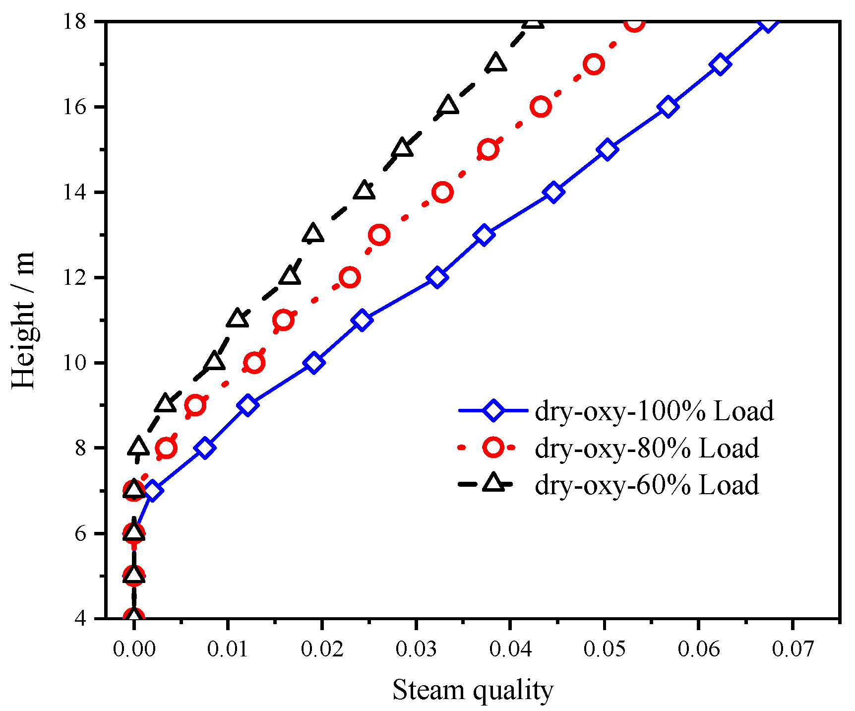
As seen in Figure 9, the steam quality varied at the width of 2.36 m on the front water wall under the three typical loads in the oxy-fuel dry FGR combustion condition. The steam quality rose with the increment of height. As the load increased, the starting point of the gas vaporization advanced, and the steam quality increased. The present study demonstrates that the heat transfer to the membrane wall has a similar property under a 28% concentration of dry FGR oxy-fuel combustion.

Figure 9.
Steam quality on the front water wall under the dry FGR condition.
4. Conclusions
- (1)
- A distribution parameter model for the evaporation system was developed in a 35 MW natural circulation air/oxy-fuel combustion boiler. Comparing the calculated value of the wall temperature with the measured value, it was found that the maximum relative error was 2.14%, which was located at the width of 2.58 m under the condition of oxy-fuel dry FGR combustion at 80% load, and the error was within a reasonable range. Therefore, the model proposed in this paper can produce correct predictions.
- (2)
- When compared to the conventional air combustion, the water wall heat flux in the oxy-fuel dry/wet FGR combustion conditions remained even and uniform at the same load due to the changes of the specific heat, the diffusion, and the radiation coefficient of the three atomic gases (CO2 and H2O). The flue gas temperature in the oxy-fuel wet FGR combustion was much higher than that in the dry FGR situation, and the metal temperature in the oxy-fuel dry FGR condition was lower than that in other two operation modes. Therefore, the wall heat flux distribution and the wall temperature distribution of the oxy-fuel dry FGR combustion were the most uniform and reasonable.
- (3)
- This subject effectively integrated the numerical simulation information of the furnace side with the thermal system model of the boiler side, and the research results provided novel guidance for the design, operation, and diagnosis of large capacity oxy-fuel combustion boilers.
Author Contributions
Project administration, Z.L.; Investigation, B.W.; Writing—original draft, Z.F. and Q.C.; Writing—review and editing, Z.L. All authors have read and agreed to the published version of the manuscript.
Funding
This research was funded by the National Natural Science Foundation of China (no. 51776078).
Conflicts of Interest
The authors declare no conflict of interest.
Nomenclature
| specific isobaric heat capacity | |
| diameter | |
| mass flow rate | |
| flow area | |
| acceleration of gravity | |
| mass velocity | |
| specific enthalpy | |
| height | |
| mass | |
| Nusselt number | |
| pressure | |
| Prandtl number | |
| heat flux | |
| heat flow rate | |
| Reynolds number | |
| surface area | |
| absolute temperature | |
| specific internal energy | |
| volume | |
| steam quality | |
| Martinelli number | |
| latent heat of vaporization | |
| heat conductivity coefficient | |
| F | Reynolds factor |
| Greek symbols | |
| heat transfer coefficient | |
| frictional resistance coefficient | |
| difference in any quantity | |
| emissivity | |
| absorption coefficient | |
| thermal conductivity | |
| dynamic viscosity | |
| resistance coefficient | |
| density | |
| Stefan-Boltzmann constant | |
| velocity | |
| Subscripts | |
| number of element | |
| liquid | |
| G | gas |
| maximum value | |
| inner | |
| outer | |
| water wall | |
| saturation | |
| inlet | |
| outlet | |
References
- Li, S.; Xu, Y.; Gao, Q. Measurements and modelling of oxy-fuel coal combustion. Proc. Combust. Inst. 2019, 37, 2643–2661. [Google Scholar] [CrossRef]
- Guo, J.; Liu, Z.; Wang, P.; Huang, X.; Li, J.; Xu, P.; Zheng, C. Numerical investigation on oxy-combustion characteristics of a 200MWe tangentially fired boiler. Fuel 2015, 140, 660–668. [Google Scholar] [CrossRef]
- Nakod, P.; Krishnamoorthy, G.; Sami, M.; Orsino, S. A comparative evaluation of gray and non-gray radiation modeling strategies in oxy-coal combustion simulations. Appl. Therm. Eng. 2013, 54, 422–432. [Google Scholar] [CrossRef]
- Black, S.; Szuhánszki, J.; Pranzitelli, A.; Ma, L.; Stanger, P.; Ingham, D.; Pourkashanian, M. Effects of firing coal and biomass under oxy-fuel conditions in a power plant boiler using CFD modelling. Fuel 2013, 113, 780–786. [Google Scholar] [CrossRef]
- Gani, Z.F.A.; Pandian, P.A. Modelling of coal combustion in a drop tube furnace in air and oxy fuel environment. Mater. Today Proc. 2021, 47, 4431–4437. [Google Scholar] [CrossRef]
- Ahn, J.; Kim, H.-J. Combustion characteristics of 0.5 MW class oxy-fuel FGR (Flue Gas Recirculation) boiler for CO2 capture. Energies 2021, 14, 4333. [Google Scholar] [CrossRef]
- De Kerret, F.; Béguin, C.; Etienne, S. Two-phase flow pattern identification in a tube bundle based on void fraction and pressure measurements, with emphasis on churn flow. Int. J. Multiph. Flow 2017, 94, 94–106. [Google Scholar] [CrossRef]
- Guzella, M.; Czelusniak, L.; Mapelli, V.; Alvariño, P.; Ribatski, G.; Cabezas-Gómez, L. Simulation of boiling heat transfer at different reduced temperatures with an improved pseudopotential lattice boltzmann method. Symmetry 2020, 12, 1358. [Google Scholar] [CrossRef]
- Weise, S.; Dietrich, B.; Wetzel, T. Flow-pattern based prediction of flow boiling heat transfer in horizontal tubes with circumferentially varying heat flux. Int. J. Heat Mass Transf. 2020, 148, 119018. [Google Scholar] [CrossRef]
- Wu, J.; Li, X.; Liu, H.; Zhao, K.; Liu, S. Calculation method of gas–liquid two-phase boiling heat transfer in helically-coiled tube based on separated phase flow model. Int. J. Heat Mass Transf. 2020, 161, 120242. [Google Scholar] [CrossRef]
- Zheng, J.X.; Chen, T.K.; Chen, X.J.; Yang, D. Dynamic thermal-hydraulic models for single-phase heated tubes. Adv. Mech. 1997, 27, 538–547. [Google Scholar]
- Li, H.; Huang, X.; Zhang, L. A lumped parameter dynamic model of the helical coiled once-through steam generator with movable boundaries. Nucl. Eng. Des. 2008, 238, 1657–1663. [Google Scholar] [CrossRef]
- Yu, T.; Yuan, J. Evaporation system modeling of the utility boiler aiming at real-time estimation of the heat flux into water walls. IFAC Proc. Vol. 2013, 46, 581–584. [Google Scholar] [CrossRef]
- Laubscher, R.; Rousseau, P. CFD study of pulverized coal-fired boiler evaporator and radiant superheaters at varying loads. Appl. Therm. Eng. 2019, 160, 114057. [Google Scholar] [CrossRef]
- Tang, G.; Zhang, M.; Gu, J.; Wu, Y.; Yang, H.; Zhang, Y.; Wei, G.; Lyu, J. Thermal-hydraulic calculation and analysis on evaporator system of a 660 MWe ultra-supercritical CFB boiler. Appl. Therm. Eng. 2019, 151, 385–393. [Google Scholar] [CrossRef]
- Chu, Y.-T.; Lou, C.; Cheng, Q.; Zhou, H.-C. Distributed parameter modeling and simulation for the evaporation system of a controlled circulation boiler based on 3-D combustion monitoring. Appl. Therm. Eng. 2008, 28, 164–177. [Google Scholar] [CrossRef]
- Zheng, S.; Luo, Z.; Zhang, X.; Zhou, H. Distributed parameters modeling for evaporation system in a once-through coal-fired twin-furnace boiler. Int. J. Therm. Sci. 2011, 50, 2496–2505. [Google Scholar] [CrossRef]
- Shu, Z.; Zixue, L.; Yanxiang, D.; Huaichun, Z. Development of a distributed-parameter model for the evaporation system in a supercritical W-shaped boiler. Appl. Therm. Eng. 2014, 62, 123–132. [Google Scholar] [CrossRef]
- Laubscher, R.; van der Merwe, S. Heat transfer modelling of semi-suspension biomass fired industrial watertube boiler at full- and part-load using CFD. Therm. Sci. Eng. Prog. 2021, 25, 100969. [Google Scholar] [CrossRef]
- Laubscher, R.; De Villiers, E. Integrated mathematical modelling of a 105 t/h biomass fired industrial watertube boiler system with varying fuel moisture content. Energy 2021, 228, 120537. [Google Scholar] [CrossRef]
- Guo, J.; Liu, Z.; Huang, X.; Zhang, T.; Luo, W.; Hu, F.; Li, P.; Zheng, C. Experimental and numerical investigations on oxy-coal combustion in a 35 MW large pilot boiler. Fuel 2017, 187, 315–327. [Google Scholar] [CrossRef]
Publisher’s Note: MDPI stays neutral with regard to jurisdictional claims in published maps and institutional affiliations. |
© 2022 by the authors. Licensee MDPI, Basel, Switzerland. This article is an open access article distributed under the terms and conditions of the Creative Commons Attribution (CC BY) license (https://creativecommons.org/licenses/by/4.0/).