Article

Corona Characteristics of a Large-Sized AC Grading Ring and Prediction of Corona Onset Field Intensity

1
State Grid Hebei Electric Power Research Institute, Shijiazhuang 050021, China
2
Hebei Provincial Key Laboratory of Power Transmission Equipment Security Defense, North China Electric Power University, Baoding 071003, China
3
State Grid Hebei Xingtai Power Supply Company, Xingtai 054001, China
*
Author to whom correspondence should be addressed.
Energies 2022, 15(6), 2041; https://doi.org/10.3390/en15062041
Submission received: 24 January 2022 / Revised: 28 February 2022 / Accepted: 8 March 2022 / Published: 10 March 2022

Abstract

:
In order to ensure that corona discharge does not occur in the grading ring under normal operation, this paper studies corona characteristics of large-sized AC grading rings and a prediction method for corona onset field intensity (COI). First of all, a three-dimensional (3-D) finite element simulation model of the electrostatic field is established for the grading ring area where corona discharge is relatively serious in a typical EHV AC substation. The distribution law for electric field intensity of saddle-type and elliptical (circular) grading rings is calculated and analyzed, from which the result shows that pipe diameter is the main factor affecting the maximum electric field intensity (MEI) of grading rings with different structures; with continuous increase in pipe diameter, the MEI of grading rings tends to be saturated gradually. In addition, the COI tests of grading rings are carried out and test results are compared with calculation results obtained based on the Peek formula, which shows that the Peek formula has a large error in predicting the COI of a grading ring. Finally, based on test results of the COI, a formula for predicting the COI of an AC grading ring in a plain area with an altitude of 100 m is proposed by considering the effect of both the pipe diameter and the ring diameter.

1. Introduction

With continuous improvement in the voltage level of power systems, the electromagnetic environmental problems caused become increasingly prominent. Corona noise, radio interference, electrostatic effect, and other hazards caused by corona discharge have attracted more and more attention [1,2,3]. Relevant research results show the corona discharge of a grading ring in EHV AC transmission and transformation projects in China is very serious and has become one of the main factors of electromagnetic environment pollution. Long-term corona discharge will not only affect stable and reliable operation of high-voltage equipment, but also increase the maintenance cost of equipment [4,5]. Therefore, it is necessary to ensure that corona discharge does not occur in the grading ring under normal operation.
It is important to strictly ensure the maximum electric field intensity (MEI) on the grading ring surface is lower than the corona onset field intensity (COI) under any operational environment and operation mode. China Electric Power Research Institute has carried out simulation modeling research on single V-shaped composite insulator suspension strings of approximately 800 kV UHV DC transmission lines and put forward an optimal configuration scheme for a composite insulator grading ring [6]. State Grid Electric Power Research Institute has carried out study on the voltage distribution of insulator strings and the optimal configuration of grading rings for 750 kV double-circuit compact transmission lines on the same tower and put forward the optimal design scheme of grading rings combining optimal calculation and tests [7]. Nowadays, study on corona characteristics of grading rings is mainly to optimize structural parameters of grading rings through finite element simulation analysis, while there is little systematic study on influencing factors for corona characteristics of grading rings with different structures and sizes.
Nowadays, study on the COI of charged conductors mainly focuses on coaxial cylindrical electrode structures. Based on a large number of test data, Peek first proposed a semi-empirical formula for calculating the COI of coaxial cylindrical electrode structure [8]. Hereafter, a large number of scholars have revised the Peek formula [9,10,11,12,13]. In addition, some scholars use the Peek formula to calculate the COI of grading ring structures [14,15]. However, because the Peek formula is obtained by studying thin conductors with a curvature radius of less than 50 mm, there is a large error when using it to predict the COI of electrodes with large curvature radiuses and non-cylindrical structures. The prediction method of the COI of the grading ring is mainly to study the numerical relationship between COI and pipe diameter and between COI and ring diameter on the basis of a large number of test data, and consider the influence of environmental parameters, so as to carry out the nonlinear fitting of the COI calculation formula. Moreover, due to limitations of test conditions, there is little experimental study on corona characteristics of grading rings at home and abroad. Therefore, a systematic method to predict the COI of a grading ring has not yet been formed.
Based on the above analysis, this paper firstly establishes a three-dimensional (3-D) finite element simulation model for the electrostatic field in the area of a grading ring where the corona discharge is relatively serious in typical 500 kV EHV AC substations, calculates its surface field intensity distribution, and studies the influence law of structure and size on the MEI of the grading ring. In addition, the COI tests of grading rings are carried out in an UHV AC test base and test results are compared with calculation results obtained based on the Peek formula. Finally, based on test results of the COI, a formula for predicting the COI of an AC grading ring in a plain area with an altitude of 100 m is proposed.

2. Calculation of Electric Field Distribution on the Grading Ring Surface and Study on Its Influence Law

There are two main structural forms of terminal insulator string grading rings for EHV transmission and transformation projects. One is a saddle-type grading ring, which is mainly installed on the high voltage side of a V-shaped insulator string. The other is an elliptical and circular grading ring, which is mainly installed on the high voltage side of tensile insulator strings and post insulator strings. Because the two types of grading rings have different structural forms, the distribution of the electric field on their surfaces is different.

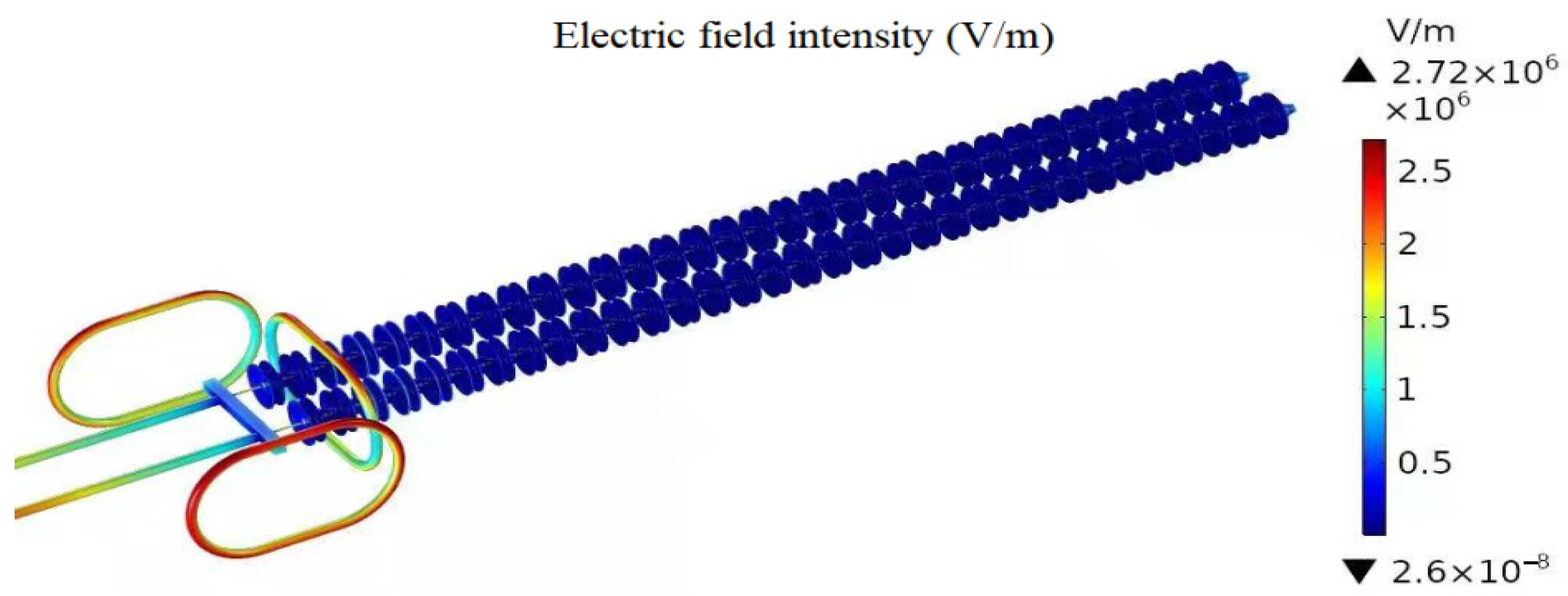
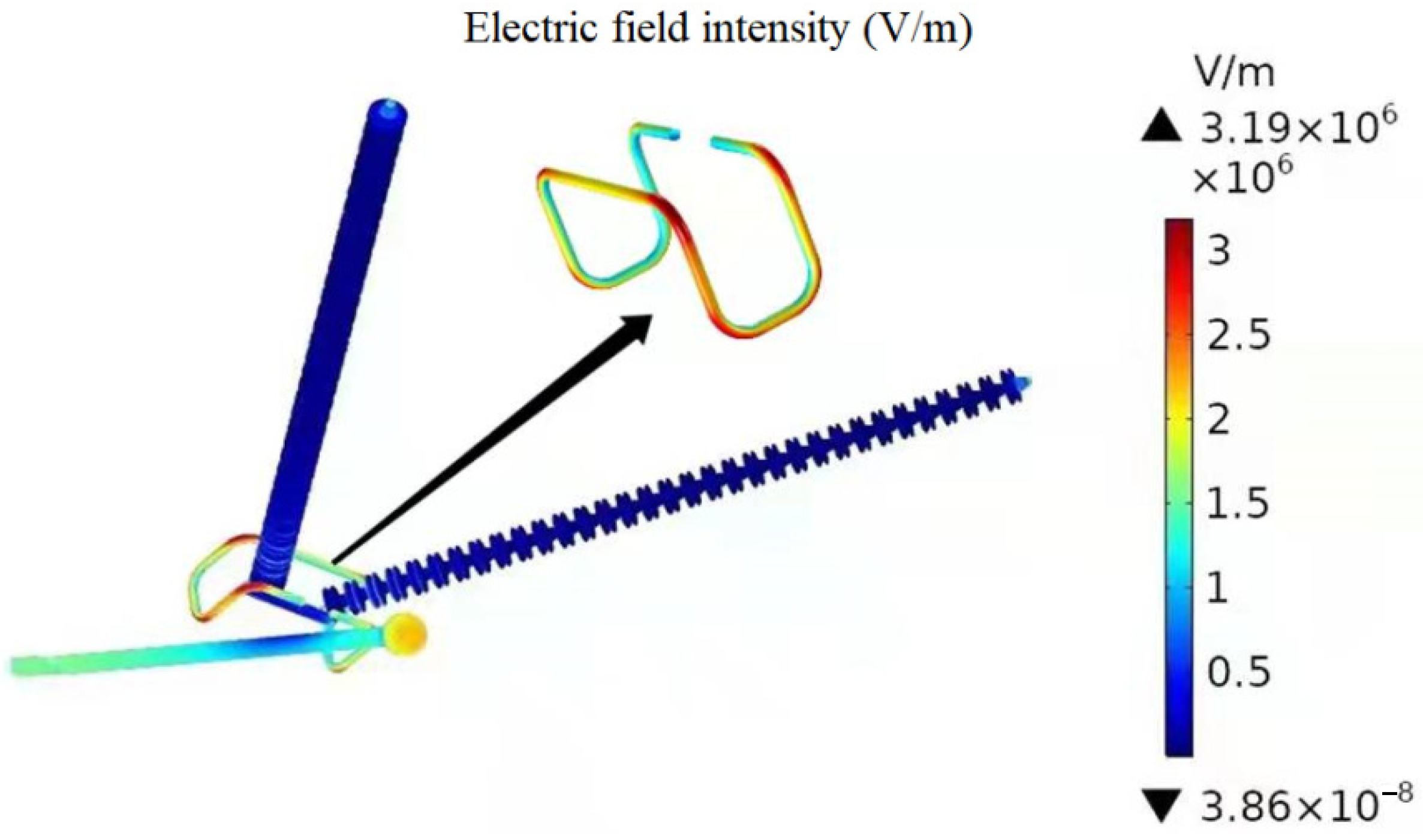
2.1. The Saddle Type Grading Ring

2.1.1. Calculation of Electric Field Distribution

The corona discharge condition of V-shaped suspension insulator string grading ring of No.1 bus of a 500 kV substation observed in sunny and windless weather conditions by using DayCor Superb ultraviolet imager is shown in Figure 1. The corona discharge of the grading ring is mainly concentrated in the arc at the corner of the grading ring.
The type of the grading ring of the V-shaped suspension insulator string of No. I bus is JPL-1200 × 860, and pipe diameter is 50 mm. The V-shaped insulator string consists of 33 pieces of XWP2-100 insulators and the length of the insulator string and connecting fittings is 5.4 m. The 3-D simulation calculation model of the electrostatic field in the grading ring area of a V-shaped suspension insulator string established in COMSOL finite element simulation software is shown in Figure 2.
The high potential of U m = 500   kV × 1.1 × 2 3 = 449.073   kV is applied to the grading ring, connecting fittings at the high voltage end of insulator string, tubular bus and shielding ball, and the potential for the connecting fittings at the low voltage end of insulator string, ground and outer air boundary is set to 0 kV. The electric field distribution on the surface of a V-shaped suspension insulator string grading ring is shown in Figure 3. The MEI on the grading ring surface is 31.92 kV/cm, and the MEI value is concentrated in the arc at the corner of the grading ring (see Figure 3), which is consistent with the field observation results of corona discharge in Figure 1.

2.1.2. Influence Law of Electric Field Distribution

When a certain voltage is applied, the MEI on the saddle type grading ring surface appears in the arc at the corner of the grading ring, so the main factors affecting the MEI of the saddle type grading ring are pipe diameter and the curvature radius of arc. When the voltage of 449.073 kV is applied and the pipe diameter and the curvature radius of the arc of the grading ring are changed, the simulation results of the MEI on the grading ring surface are shown in Figure 4.
When the pipe diameter increases from 50 mm to 100 mm, the MEI of the grading ring decreases by 33.58%, with a significant decrease (see Figure 4a); when the curvature radius of arc increases from 150 mm to 270 mm, the MEI of the grading ring decreases by 11.90%, with a relatively slow decrease (see Figure 4b). Therefore, it can be shown that the change of pipe diameter has a more significant effect on the distortion of the MEI on the surface than the change of the curvature radius of the arc of the saddle type grading ring [16].
In addition, with continuous increase of the pipe diameter and the curvature radius of the arc of a saddle type grading ring, the MEI of the saddle type grading ring tends to be saturated gradually, that is, the magnitude of decrease of the MEI on the saddle type grading ring sueface gradually decreases.

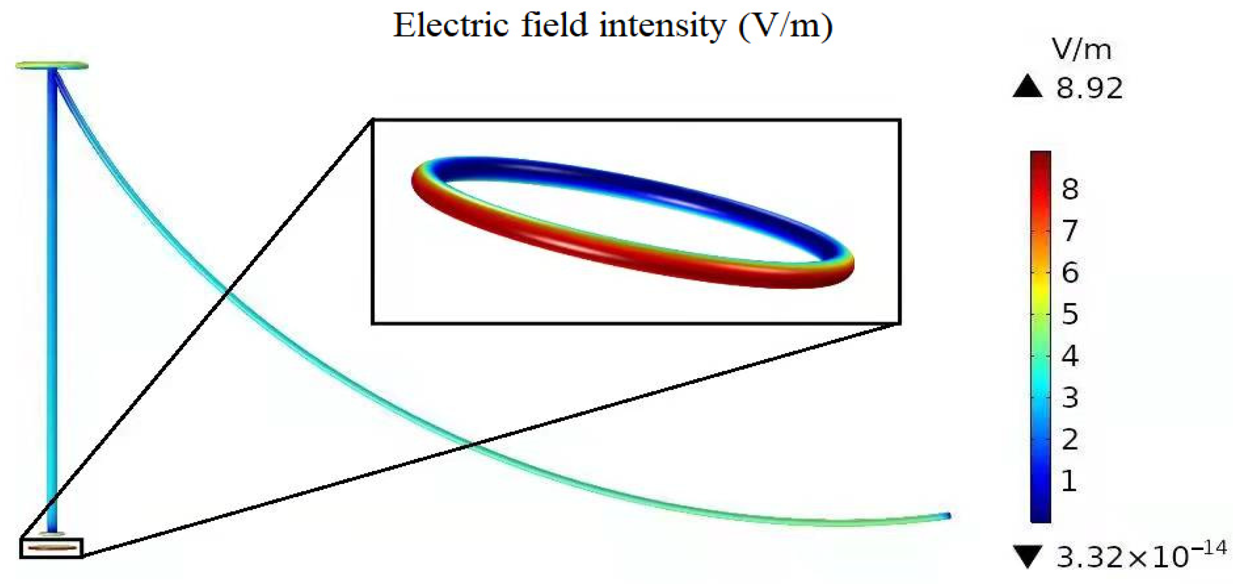
2.2. The Elliptical and Circular Grading Ring

2.2.1. Calculation of Electric Field Distribution

The coronal discharge condition of a tension insulator string grading ring and shielding ring at the outgoing side of phases A, B and C of the main transformer in a 500 kV substation observed in sunny and windless weather conditions by using DayCor Superb ultraviolet imager is shown in Figure 5. The corona discharge of a tension insulator string grading ring and shielding ring at the outgoing side of phases A, B and C of main transformer in 500 kV Substation is mainly concentrated at the arc runways of shielding rings on both sides.
The type of the grading ring of the tension insulator string on the outgoing side is FJ-1026 × 676S, and the type of shielding rings on both sides is FJ-1060 × 660S. The pipe diameter and ring diameter of the grading ring and the shielding rings are 50 mm and 660 mm respectively. The tension insulator string consists of 33 pieces of XWP2-160 insulators and the length of the insulator string and connecting fittings is 6.5 m. The 3-D simulation calculation model of the electrostatic field in the grading ring and shielding ring areas of tension insulator strings established in COMSOL finite element simulation software is shown in Figure 6.
Grading ring, shielding ring, connecting fittings at the high voltage end of insulator string, and the conductor is loaded with a high potential of U m = 500   kV × 1.1 × 2 3 = 449.073   kV , and the potential of connecting fittings at the low voltage end of insulator string, ground and outer air boundary is set to 0 kV. The electric field distribution of the tension insulator string grading ring and shielding rings is shown in Figure 7. The MEI on the grading ring surface and shielding ring surfaces on both sides is 27.23 kV/cm, and the MEI value is concentrated in the arc runway of shielding rings on both sides, which is consistent with the field observation results of corona discharge in Figure 5. In addition, the average electric field intensity of the grading ring is smaller than of the shielding rings on both sides due to the shielding effect of the shielding rings on both sides of the grading ring.

2.2.2. Influence Law of Electric Field Distribution

When a certain voltage is applied, the MEI on the surface of elliptical shielding rings appears at the arc runways of the shielding ring, so the main factors affecting the MEI of elliptical and circular grading rings (shielding rings) are the pipe diameter and ring diameter [17]. When a voltage of 449.073 kV is applied and the pipe diameter and ring diameter of shielding rings are changed, the simulation results of the MEI on the shielding ring surfaces are shown in Figure 8.
With the increase of the pipe diameter and ring diameter of shielding rings on both sides, the MEI of the shielding ring gradually decreases (see Figure 8). When pipe diameter increases from 50 mm to 100 mm, the MEI on the shielding ring surfaces decreases by 27.65%, with a significant decrease. When ring diameter increases from 660 mm to 1060 mm, the MEI on the shielding ring surfaces decreases by 4.59%, with a relatively slow decrease. Therefore, it can be shown the change of pipe diameter has a more significant effect on the distortion of the MEI of grading rings (shielding rings) than the change of the ring diameter of the elliptical and circular grading rings (shielding rings) [16,17,18]. Compared with the saddle type grading ring, although the positions and values of the MEI on the grading ring surface with different structures are different under the same voltage, the MEI is most affected by the pipe diameter of the grading ring.
In addition, Figure 8 also shows the MEI on the surface of the circular shielding rings with the same pipe diameter and ring diameter as elliptical shielding rings. When the same voltage is applied to the elliptical shielding ring and the circular shielding ring with the same pipe diameter and ring diameter, the electric field intensity on their surfaces changes little. Therefore, it can be seen the main structures affecting the MEI of the grading rings (shielding rings) are the pipe diameter and ring diameter. In addition, with continuous increase of pipe diameter and ring diameter of the elliptical and circular grading rings (shielding rings), the MEI of the elliptical and circular grading rings (shielding rings) tends to be saturated gradually, that is, the magnitude of decrease of the MEI of the elliptical and circular grading rings (shielding rings) gradually decreases.

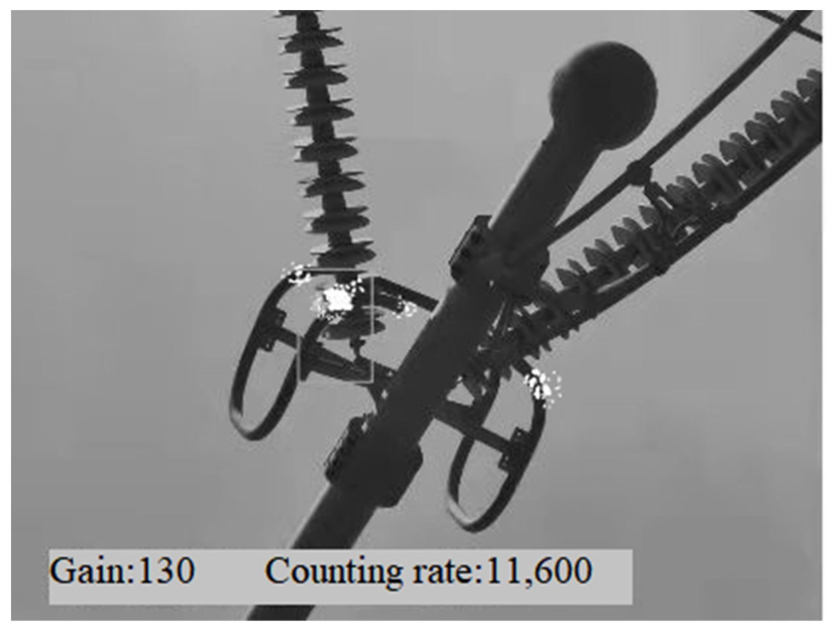
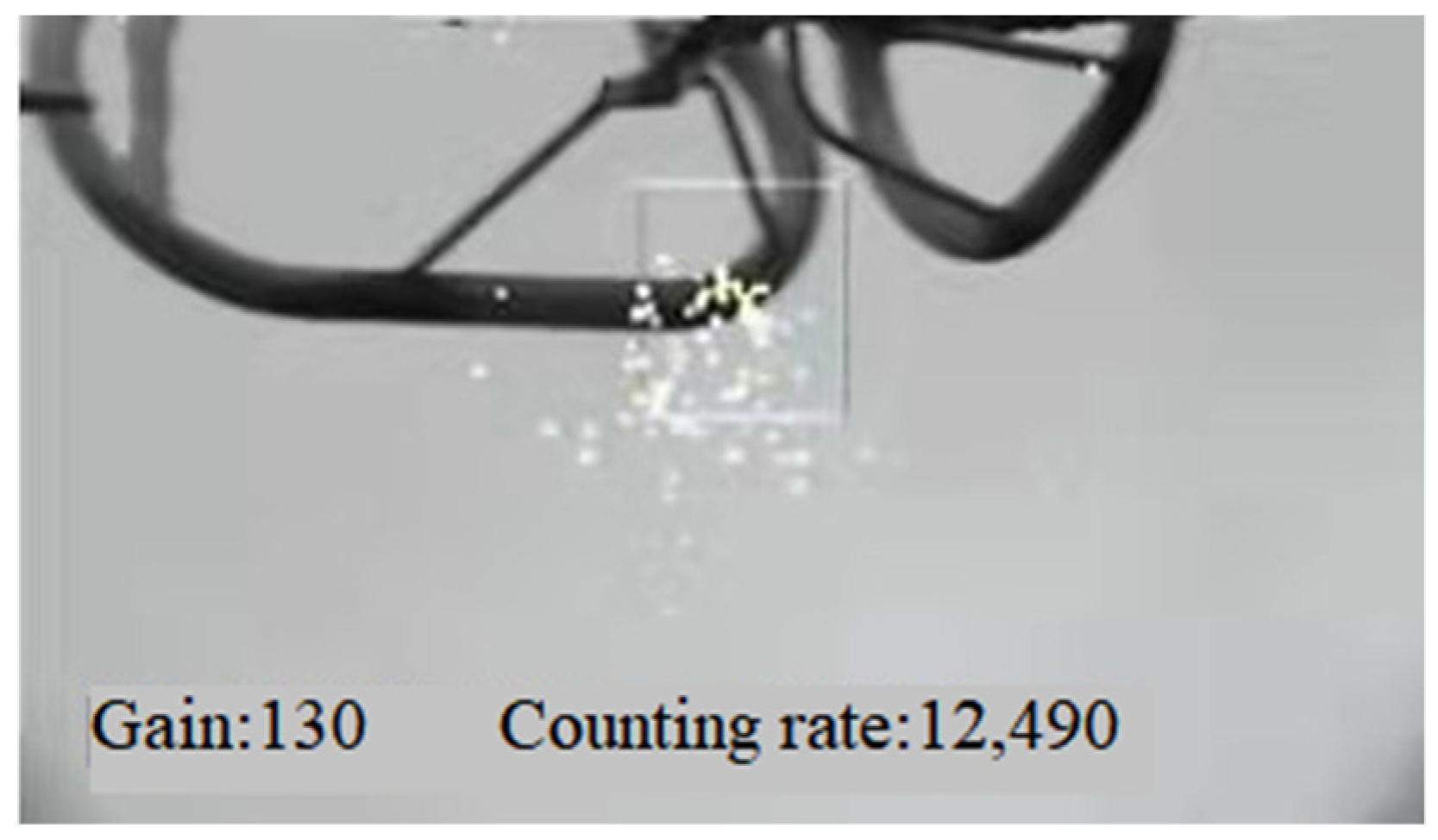
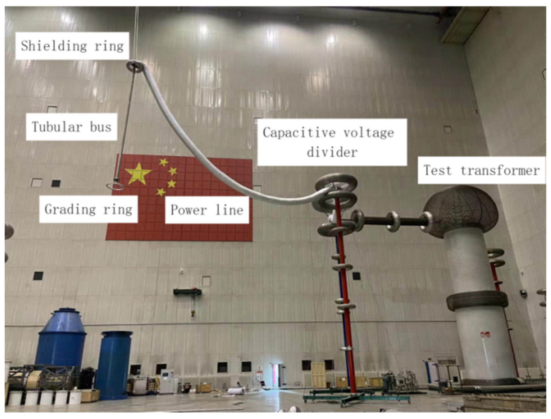
3. The COI Tests of Grading Rings

3.1. The COI Test Results

The COI tests of grading rings are carried out in the test hall of Changping UHV AC/DC test base of China Electric Power Research Institute at an altitude of 100 m. The test sample is hung on a movable overhead crane at the top of the hall. The movable overhead crane at the top of the hall is a good insulator, and it has been safely and reliably grounded in the process of design and installation. In addition, the air gap distance between the test object and the movable overhead crane at the top of the hall is greater than 15 m, which can ensure that it will not affect the test results. The length and the diameter of the tubular bus for hanging the grading ring are 6.8 m and 130 mm respectively; in addition, the distance between other equipment in the hall and the test sample is more than 15 m. Height of the grading ring from the ground is 10 m. The test layout is shown in Figure 9.
The test was conducted according to GB/T 2317.2-2008 [19]. The surface of the grading ring of the test object shall be polished before the test voltage is increased to avoid the tip on the grading ring surface, which will affect the electric field intensity near it. During the test, AC voltage shall be applied to the grading ring, and the voltage shall be increased from 200 kV. The method of step-by-step voltage increase shall be adopted. At the beginning of voltage increase, the voltage shall be increased by 50 kV each time. According to the test experience, when the loading voltage is close to the COV of the test object grading ring, apply 10 kV each time, and observe with the ultraviolet imager at the same time to judge whether the test object grading ring has corona discharge. In order to eliminate the error caused by test dispersion, each group of tests shall be repeated at least 3~5 times during the test. After eliminating the data with obvious problems, take the average value to obtain the COV of each test grading ring.
The magnitude of the COV can be obtained directly from the COI tests of grading rings; however, in order to obtain the COI of grading rings, it is necessary to establish a 3-D finite element electrostatic field simulation model based on the COI test model of grading rings. Because there is a linear relationship between the numerical value of electric field intensity and applied voltage in the calculation of the electrostatic field [20], the COI can be obtained through multiplying the MEI of a grading ring at a unit voltage obtained in the calculation of electric field distribution by the COV obtained in the test.
Figure 10 shows calculation results of electric field distribution of the COI test model under a unit voltage by taking a circular grading ring with a pipe diameter of 40 mm and a ring diameter of 800 mm as an example. Among them, 1 V voltage is applied to the grading ring, the shielding rings at the ends, suspension tubular bus and the power line, and zero potential is applied for the outer air boundary. According to the COV measured by the test and the MEI on the grading ring surface under a unit voltage obtained by finite element simulation, the calculated COI of grading rings with different sizes and structures is shown in Table 1, Table 2 and Table 3.

3.2. The COI Test and Calculation Results Analysis

When the pipe diameter and ring diameter are the same, the COV and the COI of the elliptical grading rings with different lengths remain basically unchanged (see Table 3). By comparing the numerical values of the COI of the circular grading rings with the same pipe diameter and ring diameter in Table 1 and Table 2, it can be shown the COI of the grading ring is mainly affected by pipe diameter and ring diameter.
At present, a unified and relatively accurate formula for calculating the COI of a grading ring has not yet been formed, so most scholars mainly use the Peek formula to solve it. In 1911, Peek, a American engineer, carried out a series of tests and studies on coaxial cylindrical electrodes [8]. He summed up a semi-empirical formula for calculating the COI of coaxial cylindrical electrodes (namely the famous Peek formula) by considering the roughness of the electrode surface and the influence of environmental factors such as atmospheric pressure and temperature [8]:
E o n s e t = E 0 m δ ( 1 + k δ r 0 )
where: E o n s e t is the COI on the electrode surface (kV/cm); m is the roughness coefficient of the electrode surface, it is generally between 0 and 1; δ is the relative air density, which is a function of atmospheric pressure and temperature; r 0 is the radius of coaxial cylindrical electrodes (cm); E 0 and k are constants, which are related to the type and polarity of applied voltage. For the grading ring with a smooth surface under AC voltage, E 0 = 21.92   kV cm , k = 0.308 and m = 1 .
The comparison between the calculated results and test results of the COI of grading rings with different pipe diameters is shown in Figure 11. The COI of a grading ring calculated based on the Peek formula is smaller than the test value, and the error between them is relatively large. On the one hand, the Peek formula is obtained by studying thin conductors with a curvature radius of less than 50 mm. There is a large error when using it to predict the COI of electrodes with a large curvature radius. On the other hand, the COI of a grading ring is not only related to pipe diameter, but also related to ring diameter (see Table 1 and Table 2), so the curvature radius in the Peek formula cannot be defined simply by the pipe diameter.

4. Prediction Method of the COI of an AC Grading Ring

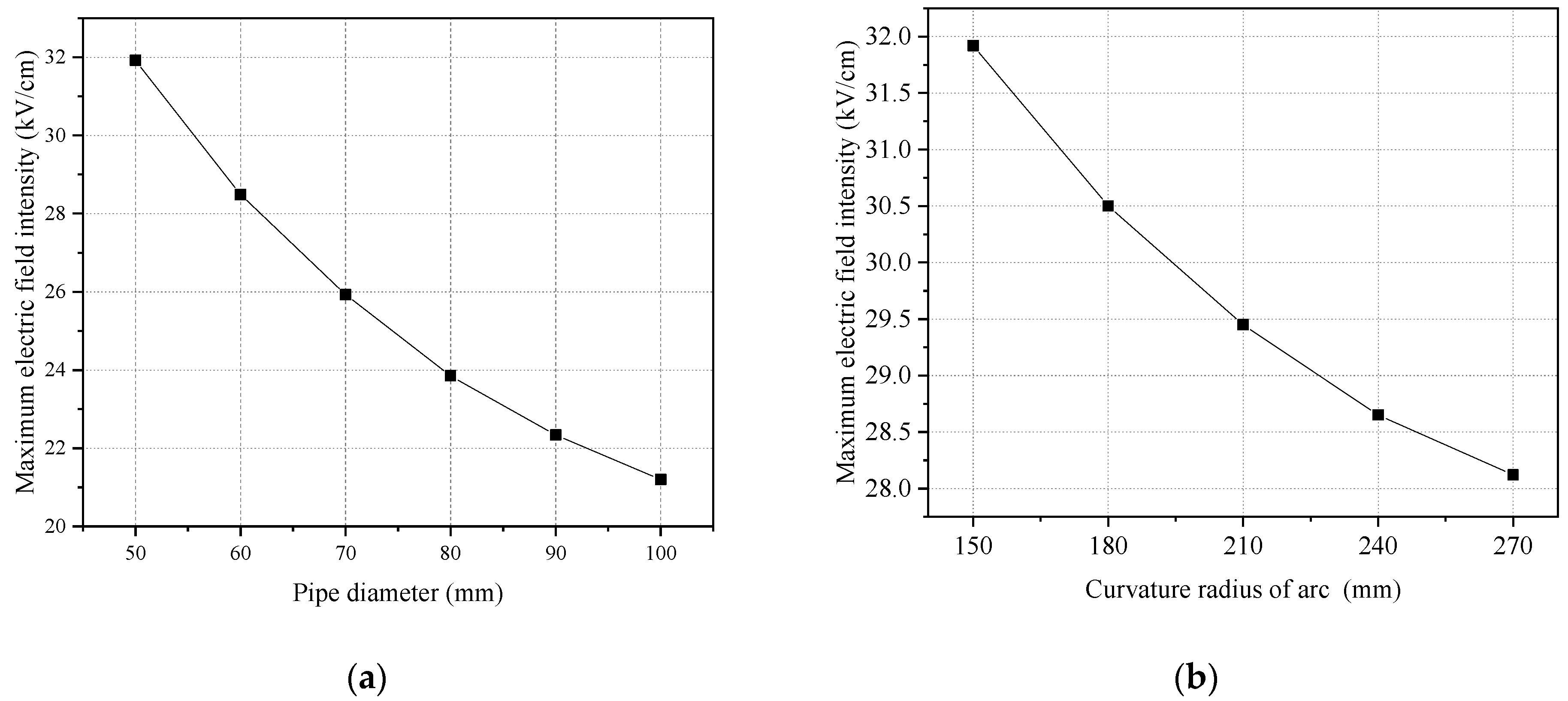
4.1. Influence of Pipe Diameter on the COI of a Grading Ring

Curve fitting is carried out for the COI of a grading ring with a pipe diameter between 40 mm and 120 mm by using Formula (2) and the parameters a 1 , b 1 , c 1 are solved by using the least square method. See Figure 12 for comparison between the test results of the COI and the fitting curve.
E o n s e t = a 1 × r b 1 + c 1
In the fitting curve, a 1 = 37.95 , b 1 = 0.296 , c 1 = 18.22 , the correlation coefficient is 0.9995, the standard deviation is 0.03075, with good fitting effect. With the increase of the pipe diameter of the grading ring, the COI decreases nonlinearly, and the magnitude of the decrease is different for grading rings with different pipe diameters (See Figure 12). For example, for grading rings with pipe diameters between 40 mm and 90 mm, the COI decreases rapidly with the increase of the pipe diameter, with a relatively large decrease magnitude. For grading rings with pipe diameters between 90 mm and 120 mm, the COI decreases slowly with the increase of pipe diameter, with a certain saturation trend.

4.2. Influence of Ring Diameter on the COI of a Grading Ring

Curve fitting is carried out for the COI of the grading ring with ring diameters between 620 mm and 860 mm by using Formula (3) and the parameters a 2 and b 2 are solved by using the least square method. See Figure 13 for comparison between the test results of the COI and the fitting curve.
E o n s e t = a 2 × R b 2
In the fitting curve, a 2 = 70.61 and b 2 = 0.131 , the correlation coefficient is 0.9946, the standard deviation is 0.03444, with good fitting effect. With the increase of the ring diameter of the grading ring, the COI decreases nonlinearly (see Figure 13). By comparing the numerical values of b 1 and b 2 , it can be seen that compared with pipe diameter, which has a more significant distortion effect on the COI of the grading ring, the ring diameter has less distortion effect on the COI of the grading ring, but it still shows the COI decreases slowly with increase of the ring diameter and has a certain saturation trend.

4.3. Prediction Formula of the COI

Based on the analysis in Section 4.1 and Section 4.2, the robust items in a fitting formula of the COI with pipe diameter and ring diameter is retained, and constant C is brought for overall correction. According to the Peek formula, the COI is proportional to relative air density δ and the square root of the relative air density, so the prediction formula of the COI of AC grading rings is proposed as follows:
E o n s e t = A δ ( 1 + B 1 δ 0.5 r 0.293 R 0.131 ) + C
Multivariate nonlinear curve fitting is carried out on all the test data of the COI, and the prediction formula of the COI is shown in Formula (5): the correlation coefficient of fitting curve is 0.9886, with a good fitting effect.
E o n s e t = 3.91 δ ( 1 + 24.44 1 δ 0.5 r 0.293 R 0.131 ) + 13.59
where, 40   mm r 120   mm , 620   mm R 860   mm . This formula is applicable to plain areas with an altitude of 100 m.
See Figure 14 for comparison between the test results of the COI and fitting curve. The fitting curve of the COI obtained by using Formula (5) has good consistency with the test results.

4.4. Verification of Prediction Formula

To verify the applicability of the prediction formula of the COI of the grading ring, the test data of the COI of grading rings with different pipe diameters and different ring diameters given in references [17,21] are used. The test data of the COI in references [17,21] and the COI calculated by fitting formula and Peek formula are shown in Table 4.
Table 5 shows the relative errors between the test data and the COI calculated by the fitting formula and Peek formula. The relative error between the test data and the COI calculated by the fitting formula is far less than that between the test data and the COI calculated by Peek formula. The relative error between the test data and the COI calculated by the fitting formula is within 5%, which shows the accuracy of the prediction formula of the COI proposed in this paper.

5. Conclusions

This paper mainly studies the influencing factors of the MEI on the grading ring surface and the prediction formula of the COI of an AC grading ring.
(1)
The calculation results of the MEI on the surface of saddle type and elliptical (circular) grading rings show that pipe diameter is the main factor affecting the MEI of grading rings with different structures. With continuous increase in pipe diameter, the MEI of the grading ring is gradually saturated.
(2)
The COI tests of grading rings are carried out in the UHV AC test base, and test results are compared with calculation results obtained based on the Peek formula, which shows that the Peek formula has a large error in predicting the COI of an AC grading ring.
(3)
Based on test results of the COI, a formula for predicting the COI of an AC grading ring in a plain area with an altitude of 100 m is proposed by considering the effect of both the pipe diameter and the ring diameter.
(4)
The COI of circular and elliptical grading rings with the same pipe diameter and ring diameter remains basically unchanged. Compared with pipe diameter, which has a more significant distortion effect on the COI of the grading ring, the ring diameter has less distortion effect on the COI of the grading ring.

Author Contributions

Conceptualization, J.L. and Z.Z.; methodology, J.L. and B.J.; software, X.Y. and P.W.; validation, P.W., J.G. and X.Y.; formal analysis, J.L.; investigation, B.J.; resources, J.G.; data curation, X.Y.; writing—original draft preparation, X.Y.; writing—review and editing, P.W.; visualization, J.L.; supervision, Z.Z.; project administration, B.J.; funding acquisition, J.L. All authors have read and agreed to the published version of the manuscript.

Funding

This work is supported by Subsidiary technology project of State Grid Hebei Electric Power Co., Ltd. (kj2020-042).

Institutional Review Board Statement

Not applicable.

Informed Consent Statement

Not applicable.

Data Availability Statement

Not applicable.

Conflicts of Interest

The authors declare no conflict of interest.

References

  1. Zhou, H.; Yu, Y.H. Discussion on some important issues in the development of UHV transmission in China. Power Grid Technol. 2005, 29, 1–9. [Google Scholar]
  2. Zhang, G.Z.; Cheng, L.G.; Wan, B.Q. Electromagnetic environment and corona control measures of UHV Substation. High Volt. Technol. 2010, 36, 109–115. [Google Scholar]
  3. Wan, B.Q.; Xie, H.C.; Fan, L. Study on electromagnetic environment of AC UHV test section. High Volt. Technol. 2008, 34, 438–441. [Google Scholar]
  4. Liu, Z.Y. UHV Power Grid, 2nd ed.; China Economic Publishing House: Beijing, China, 2005; pp. 10–52. [Google Scholar]
  5. Shu, Y.B. Research and application of 1000kV UHV AC transmission technology. Power Grid Technol. 2005, 29, 1–6. [Google Scholar]
  6. Deng, T.; Su, Z.Y.; Fan, J.B. Optimal design of grading ring of composite insulator for ±800 kV UHV DC line. Power Grid Technol. 2010, 34, 31–35. [Google Scholar]
  7. Chen, Y.; Xie, X.J.; Xie, L. Optimization of voltage equalizing ring for 750 kV double circuit compact line on the same tower. High Volt. Technol. 2008, 34, 2390–2394. [Google Scholar]
  8. Peek, F.W. Dielectric Phenomena in High Voltage Engineering, 1st ed.; McGraw-Hill: New York, NY, USA, 1929; pp. 1–328. [Google Scholar]
  9. Whitehead, J.B. High-Voltage Corona, 1st ed.; McGraw-Hill: New York, NY, USA, 1929; pp. 107–108. [Google Scholar]
  10. Lowke, J.J.; D’Alessandro, F. Onset corona fields and electrical breakdown criteria. J. Phys. D Appl. Phys. 2003, 36, 2673–2682. [Google Scholar] [CrossRef]
  11. Robinson, M. The corona threshold for coaxial cylinders in air at high pressures. IEEE Trans. Power Appl. Syst. 1967, PAS-86, 185–189. [Google Scholar] [CrossRef]
  12. Waters, R.T.; Stark, B. Characteristics of stabilized glow discharge in air. J. Phys. D Appl. Phys. 1975, 8, 416–426. [Google Scholar] [CrossRef]
  13. Huang, S.L.; Liu, Y.P.; Chen, S.S. Corona onset voltage gradient of bundle conductors for EHV/UHV AC power lines in corona cages considering altitude correction. CSEE J. Power Energy Syst. 2020, 6, 693–703. [Google Scholar] [CrossRef]
  14. Chang, J.L.; Xu, G.H.; Xu, J.T. Calculation of electric field on the surface of ±1100 kV UHV valve hall fittings and corona check. High Volt. Appar. 2018, 54, 87–92, 100. [Google Scholar]
  15. Hu, R.; Jin, S. Calculation and analysis of electric field of fittings for four valve hall of ±500 kV converter station. High Volt. Appar. 2014, 50, 49–55. [Google Scholar]
  16. Wang, H.Y.; Xia, J.X.; Huang, D.C. Corona characteristics of insulator string grading ring in ultra-high altitude 500 kV substation. High Volt. Eng. 2013, 39, 661–667. [Google Scholar]
  17. Zhou, T.T.; Ruan, J.J.; Du, Z.Y. Corona characteristics of HVDC shielding fittings at high altitude. High Volt. Technol. 2017, 43, 3036–3041. [Google Scholar]
  18. Wan, B.Q.; Xie, H.C.; Fan, L. Electromagnetic environment and corona control measures of UHV Substation. High Volt. Eng. 2010, 36, 109–115. [Google Scholar]
  19. GB/T2317.2-2008; Test Methods for Power Fittings Part 2: Corona and Radio Interference Test. China Standards Press: Beijing, China, 2009.
  20. Jin, X.; Du, Z.Y.; Qiu, Z.B. Corona characteristics and corona onset voltage prediction of large diameter shielding ball. High Volt. Eng. 2019, 45, 4079–4087. [Google Scholar]
  21. Li, M.; Liu, L.; Yu, Z.Q. Prediction and correction method of corona field intensity of DC line fittings at an altitude of 2 km. South. Power Syst. Technol. 2016, 10, 55–60. [Google Scholar] [CrossRef] [Green Version]
Figure 1. The corona discharge condition of V-shaped suspension insulator string grading ring of No.1 bus of a 500 kV substation.
Energies 15 02041 g001
Figure 2. The 3-D simulation calculation model of electrostatic field in the grading ring area of V-shaped suspension insulator string.
Energies 15 02041 g002
Figure 3. The electric field distribution on the surface of a V-shaped suspension insulator string grading ring.
Energies 15 02041 g003
Figure 4. MEI on the saddle type grading ring surface with different pipe diameters and curvature radiuses of arc. (a) The MEI on the grading ring surface with different pipe diameters; (b) The MEI on the grading ring surface with different curvature radiuses of arc.
Energies 15 02041 g004
Figure 5. The coronal discharge condition of a tension insulator string grading ring and shielding ring at the outgoing side of phases A, B and C of the main transformer.
Energies 15 02041 g005
Figure 6. The 3-D simulation calculation model of the electrostatic field in the grading ring and shielding ring areas of tension insulator strings.
Energies 15 02041 g006
Figure 7. The electric field distribution of a tension insulator string grading ring and shielding rings.
Energies 15 02041 g007
Figure 8. MEI of elliptic and circular grading rings (shielding rings) with different pipe diameters and ring diameters. (a) MEI on the grading ring surface with different pipe diameters; (b) MEI on the grading ring surface with different ring diameters.
Energies 15 02041 g008
Figure 9. Layout of COI tests of grading rings.
Energies 15 02041 g009
Figure 10. Calculation results of electric field distribution of the COI test model.
Energies 15 02041 g010
Figure 11. Test and calculation results of the COI of grading rings with different pipe diameters.
Energies 15 02041 g011
Figure 12. Comparison of test and fitting results of the COI varying with pipe diameter.
Energies 15 02041 g012
Figure 13. Comparison of test and fitting results of the COI varying with ring diameter.
Energies 15 02041 g013
Figure 14. The COI calculated by the prediction formula in this paper is compared with the test results (a) Comparison of test result and fitting results on the variation of the COI changing with pipe diameter; (b) Comparison of test result and fitting results on the variation of the COI changing with ring diameter.
Energies 15 02041 g014
Table 1. COI test results of circular grading rings with ring diameter of 800 mm and different pipe diameters.
Pipe Diameter (mm)COV (kV)COI (kV/cm)Environmental Parameters
Atmospheric Pressure (kPa)Temperature (°C)Humidity (%)
4034730.939101.513.232
5038530.196100.913.132
6042329.458102.113.032
7045329.002102.512.932
8048528.605101.912.732
9051528.255102.013.032
10054127.901101.712.732
11056827.653101.812.532
12058927.455102.012.5.32
Table 2. COI test results of circular grading rings with pipe diameter of 60 mm and different ring diameters.
Ring Diameter (mm)COV (kV)COI (kV/cm)Environmental Parameters
Atmospheric Pressure (kPa)Temperature (°C)Humidity (%)
62039130.502101.312.532
65039830.303101.012.032
68040430.108101.312.532
71041029.914100.912.532
74041529.726101.912.032
77042029.593101.512.732
80042329.458102.113.032
83042829.345102.012.532
86043129.250102.012.132
Table 3. COI test results of elliptical grading rings with pipe diameter of 60 mm and ring diameter of 800 mm.
Length (mm)COV (kV)COI (kV/cm)Environmental Parameters
Atmospheric Pressure (kPa)Temperature (°C)Humidity (%)
125042529.441101.312.532
145042729.409101.012.532
Table 4. The test data of the COI in references [17,21] and the COI calculated by fitting formula and Peek formula.
Size of Grading RingCOI (kV/cm)
Pipe Diameter (mm)Ring Diameter (mm)Test DataFitting FormulaPeek Formula
8068028.8228.4725.30
8082028.4728.2125.30
5080030.2329.8526.19
7080028.8728.6825.53
9080028.1927.8725.10
Table 5. The relative errors between the test data and the COI calculated by the fitting formula and Peek formula.
Size of Grading RingRelative Error (%)
Pipe Diameter (mm)Ring Diameter (mm)Test Data and Fitting FormulaTest Data and Peek Formula
806801.2112.21
808200.9111.13
508001.2613.36
708000.6611.57
908001.1410.96
Publisher’s Note: MDPI stays neutral with regard to jurisdictional claims in published maps and institutional affiliations.

