Article

Control Strategy of Interlinking Converter in Hybrid Microgrid Based on Line Impedance Estimation

1
School of Mechanical Engineering and Automation, Harbin Institute of Technology (Shenzhen), Shenzhen 518055, China
2
Department of DC Transmission and Power Electronics, China South Grid Electric Power Research Institute, Guangzhou 510080, China
*
Author to whom correspondence should be addressed.
Energies 2022, 15(5), 1664; https://doi.org/10.3390/en15051664
Submission received: 6 December 2021 / Revised: 29 January 2022 / Accepted: 9 February 2022 / Published: 23 February 2022
(This article belongs to the Special Issue Advanced Technologies in Grid-Connected Inverters and Converters)

Abstract

:
Due to the voltage drop of the line impedance, power-transfer deviation occurs in the interlinking converter (IC) of hybrid microgrids. In this paper, an IC control strategy in hybrid microgrids is proposed, which can estimate the line resistance precisely. Moreover, the proposed method can easily realize accurate power transmission between sub-grids and maintain the power balance of hybrid microgrid. Firstly, one specified small signal is injected into the IC at the AC bus of the distributed generation so as to estimate the line impedance. The frequency of the injected small signal is highly relevant to the AC bus voltage. As a result, the IC can accurately detect its line impedance by extracting the injected small signal frequency with a filter and phase-lock-loop (PLL) without communication. Secondly, with the line impedance estimation, the voltage drop on the line can be compensated with local information of the IC, and consequently, accurate power transfer can be realized. Finally, the validity of the proposed method is verified by simulation and experiment results.

1. Introduction

Environmental issues caused by fossil fuels have been attracting more and more attention from both researchers and industries. Due to the better flexibility and eco-friendly feature, distributed generation (DG) raises the intriguing possibility that the DG involvement in the power grid could be an effective solution. Generally, the DG mainly involves the wind turbine (WT), photovoltaic (PV), and energy-storage system (ESs) and they are connected with the power system as a microgrid (MG) in order to avoid intermittent and uncertain output power of a single DG [1,2]. Currently, microgrid can be categorized into three types: the AC microgrid, DC microgrid, and hybrid AC/DC microgrid. The hybrid microgrid was believed to be the most promising type compared to the other two, because it features the strengths of both the AC microgrid and the DC microgrid [3,4,5,6,7].
The hybrid AC/DC MG is comprised of an AC sub-grid, a DC sub-grid and an interlinking converter (IC) between the two sub-grids. As the bridge connecting AC and DC sides of an MG, the IC is playing an important role for the power balance of the whole MG. To realize the autonomous power-transfer operation between AC and DC sub-grids of the hybrid MG, a normalized droop control for the IC is introduced in [8,9]. This method normalizes the AC frequency and DC voltage and uses the difference of their normalized value to get the reference of the IC power. In [10], the capacitor at the DC side is replaced by ESs. By the control of charging and discharging state of ESs, the bus voltage can be maintained at a constant value. For MG with multiple ICs, Ref. [11] proposes a unified control strategy for ICs to realize seamless power transfer and sharing between ICs. These papers all employ P/f and Q/V droop in the AC sub-grid, however, most of the MGs are introduced for the low-voltage application, where the line impedance is with resistive characteristic. In this case, P/V and Q/f droop control—such as the one proposed in [12]—is more suitable for the low-voltage scenarios. Therefore, referring to the normalized droop control introduced in [8,9], ref [13] proposes a method to transmit power bidirectionally between sub-grids by normalizing AC and DC voltage and keeping their normalized value equal with an appropriate controller. In case of multiple ICs running in parallel, Ref. [14,15] proposes a method for suppressing circulating current and improves the accuracy of power sharing among ICs. However, unlike frequency in the traditional P/f droop control, the voltage in P/V droop control is not a global variable. When the line impedance cannot be neglected, the voltage drop will cause the power-transfer deviation in the IC. To realize the accurate power transmission, the line impedance must be estimated in order to compensate its voltage drop.
Several methods have been studied to estimate the line impedance. References [16,17] inject harmonic current and extract its response voltage to obtain grid-line impedance. To respectively get resistance and reactance, two harmonic signals with different frequencies are injected at the same time. References [18,19] propose the method of exciting the resonance of LCL filter by changing parameters of PI controller, and the grid-line impedance can be calculated according to the resonance frequency. However, this method ignores the resistance of grid impedance and the quality of output power will be deteriorated during the resonance. To reduce the negative impact of the resonance, Ref. [20] detects grid impedance once it changes greatly, which can be observed by the current measurement. However, this method is still unable to obtain the grid resistance. A method based on PQ variation is proposed in [21,22]. Two different operation states are established by adjusting the PQ command of the controller, and then the resistance and reactance of the grid can be obtained respectively. However, this method can only be applied to converters adopting PQ control. Reference [23] detects grid impedance by using the inherent harmonic of inverters without injecting extra harmonic signal into the system, while the inherent harmonic signal of inverters is usually suppressed to a low level by optimizing parameters of filters, and hence, this method has its own limitation. The impedance estimation results of these methods mainly contain three parts: the line impedance, the transformer impedance and the grid impedance, and usually they are applied to analyze the stability of grid-connected inverters, which are not suitable for the IC to detect its line impedance. Therefore, the method that can be applied for the IC of MG to estimate its line impedance and compensate for it needs to be further investigated.
In this paper, the hybrid AC/DC MG (in islanded mode) has been taken as an example, in order to accurately estimate the IC line impedance and effectively achieve the voltage drop compensation, a control strategy based on the small signal injection is proposed. The specified small signal is injected into the IC at the converter of one of the distributed generations connected to the AC bus. The relationship between the AC bus voltage and the injected small signal frequency is constructed. The frequency of harmonic signal is obtained in IC side. According to the frequency of the small signal extracted at the IC using a bandpass filter and phase-lock-loop (PLL), and combing the IC local information, the line impedance can be estimated without any communications. According to the line impedance estimation, the voltage drop caused by the line impedance can be compensated and accurate power-transfer can be realized.

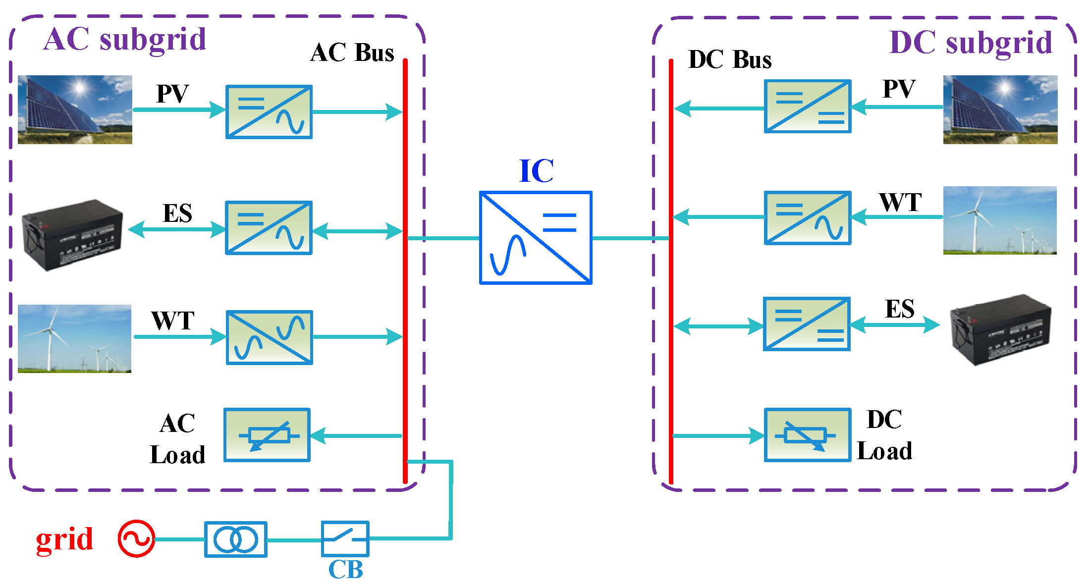
2. Structure and Control Strategy of Hybrid Microgrid

2.1. Structure of Hybrid Microgrid

The typical structure of hybrid AC/DC MG is shown in Figure 1. It can be seen clearly that the hybrid MG can operate in either grid-connected mode or islanded mode according to the state of the circuit breaker (CB). In grid-connected mode, the main grid provides strong support for the hybrid MG so that it can run stably. However, for the islanded mode, hybrid MG loses electrical connection with the main grid, and it must keep its inner power balance via the IC and maintain the entire system running stably on its own. Therefore, in islanded mode, the control strategy of hybrid MG is extremely crucial and will face more challenges. This paper is focusing on the control strategy of the IC in islanded mode.

2.2. Traditional Normalized Droop Control of IC

In conventional power system, the line reactance is much greater than the resistance, and the synchronous generator presents the external characteristics of P/f and Q/V droop. However, the MG is usually applied in low-voltage occasions, and the line impedance presents a resistive characteristic, which means that the traditional droop control cannot be adopted directly to realize power sharing between DGs running in parallel. In order to solve this problem, Ref. [24,25] add a virtual impedance to reshape the characteristic of output impedance of converters, but the large virtual inductance will inevitably lead to the output voltage drop of converters. Considering the fact that the line impedance is resistive in low-voltage situations, Ref. [12] points out that active power fluctuation of the low-voltage power system is mainly reflected in voltage change, and then the P/V and Q/f droop control is proposed, which is suitable for low-voltage MGs. Thus, this paper adopted P/V and Q/f droop in the AC sub-grid of the MG. Meanwhile, P/V droop is utilized in the DC sub-grid.
In order to realize autonomous operation of the hybrid AC/DC MG, the normalized droop control of the IC proposed in [9] is employed in this paper. To get the power reference of the IC, the AC bus voltage Vac and the DC bus voltage Vdc, representing the characteristic of the active power in the AC and DC sub-grid, are normalized according to (1) and (2) as
V a c p u = V a c 0.5 ( V a c max + V a c min ) 0.5 ( V a c max V a c min )
V d c p u = V d c 0.5 ( V d c max + V d c min ) 0.5 ( V d c max V d c min )
where Vac and Vdc are the voltage (volt, V) of the AC and DC bus, respectively. Subscripts max and min are the upper and lower limit of the corresponding variable. Vacpu and Vdcpu are the normalized value of Vac and Vdc (dimensionless) respectively.
After normalization, variables Vacpu and Vdcpu can indicate the output power condition of the sub-grids. Thus, keeping these two variables equal by means of PI controller can realize the power balance of hybrid AC/DC MG. However, unlike the frequency in traditional P/f droop control, the AC voltage Vac in P/V droop is not a global variable and the line impedance will make the output voltage of the IC inconsistent with the AC bus voltage. When the communication is unavailable, the line impedance will make the IC transmitted power deviate from its required value. Consequently, the IC would fail to realize accurate power transmission between sub-grids.

3. Line Resistance Estimation Method

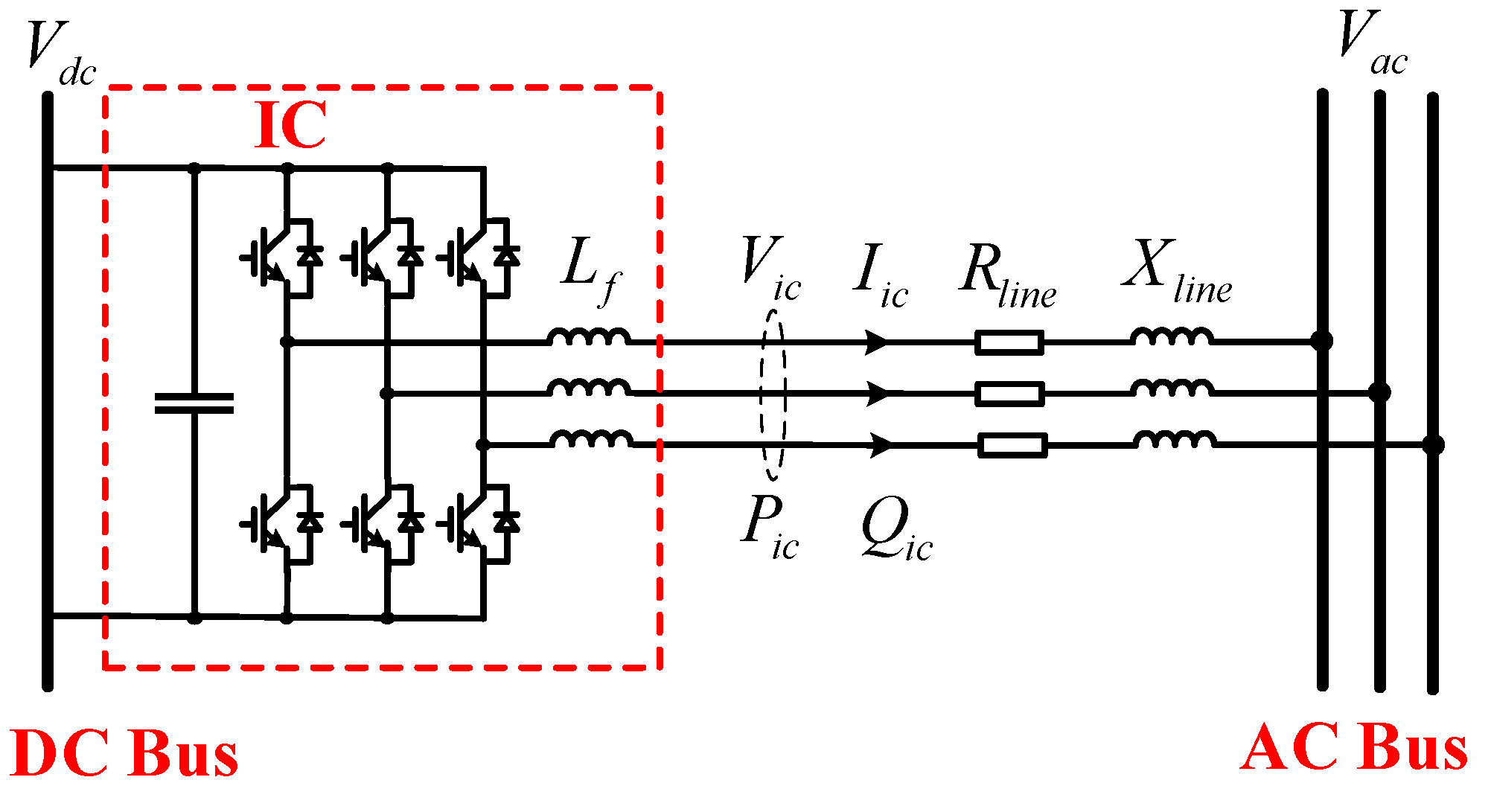
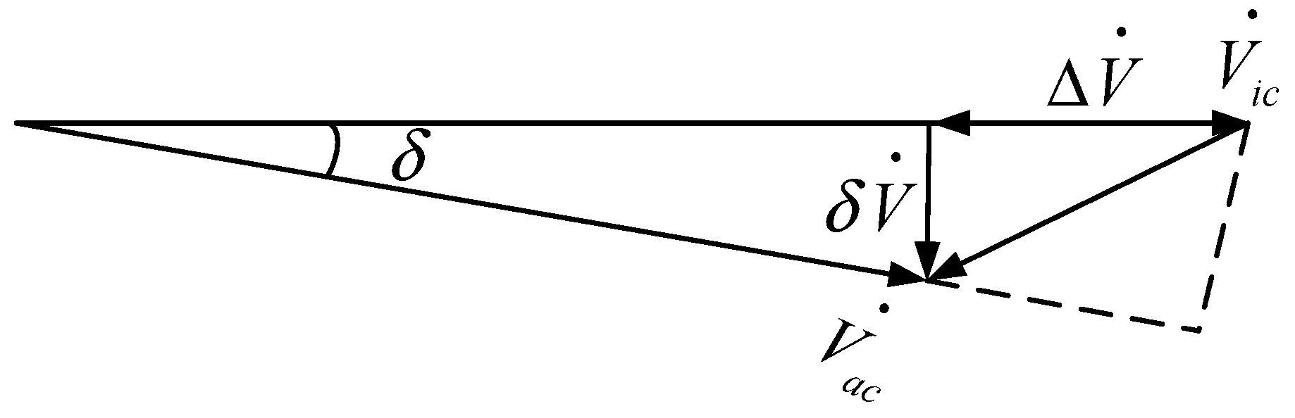
3.1. Relationship between IC Transmitted Power and Line Impedance

To accurately transmit power between sub-grids, the AC bus voltage Vac, which represents the output power of AC sub-grid, needs to be applied in the control of the IC. However, from the circuit shown in Figure 2, it can be seen that due to the existence of line impedance, the IC local voltage Vic and the AC bus voltage Vac are not the same. Since the establishment of communication system will increase the cost and reduce the reliability of hybrid AC/DC MG, it is crucial to obtain Vac based on the local information of the IC without using communication devices.
According to the schematic diagram of the IC shown in Figure 2, the following equation can be obtained:
V a c · = V i c · Z l i n e I i c ·
where Zline = Rline + jXline (Ohm, Ω).
In Equation (3), Vic and Iic are the local voltage (volt, V) and current (Ampere, A) of the IC. Once the line impedance is obtained, the IC can compensate the line voltage drop and obtain the AC bus voltage according to (3). Then, accurate power transmission of the IC will be achieved. Therefore, when the line impedance is not negligible, the line impedance estimation will be the key to realize accurate power transmission between the sub-grids. The following content will focus on the method to estimate the line impedance Zline.
For the IC shown in Figure 2, the relationship between the line impedance and the IC transmitted power can be deduced as follows.
P i c = V i c 2 Z l i n e cos φ V i c · V a c Z l i n e cos ( δ + φ )
Q i c = V i c 2 Z l i n e sin φ V i c · V a c Z l i n e sin ( δ + φ )
where φ is the impedance angle (degree, °) of Zline, δ is the phase angle difference between Vic and Vac.
Since the parameters of transmission line in different voltage level systems are not the same, it needs to be discussed at first. The following table lists the parameters of transmission line in different voltage level systems.
From Table 1, it can be seen that the line impedance ratio (R/X) of the line in low-voltage systems is much greater than that of the line in high-voltage systems. Considering the hybrid AC/DC MG is usually applied in low-voltage situation, where the line impedance is mainly resistive as shown in Table 1, this paper ignores the impact of the reactance component of the line impedance and makes the assumption that the impedance angle is zero (φ ≈ 0°). On the basis of that, Equations (4) and (5) can be rewritten as
P i c = V i c ( V i c V a c cos δ ) R l i n e
Q i c = V i c · V a c R l i n e sin δ
When the line impedance is assumed as pure resistor, it can be deduced that the voltage phase angle difference δ is zero, then (6) can be rewritten as
P i c = V i c ( V i c V a c ) R l i n e
From Equation (8), it can be seen that if Vac is given, the line resistance Rline can be obtained by using the local information of IC. Since the line resistance can be perceived as a constant, the IC can compensate voltage drop in real time according to (3). Then, accurate power transmission between sub-grids can be consequently realized without communication.

3.2. Estimation of Line Impedance by Means of Harmonic Signal Injection

According to the aforementioned analysis, Vac needs to be known by the IC and then Rline can be obtained. To get AC bus voltage Vac, the procedure of the traditional P/f droop control method can be applied and the relationship between fh and Vac will be constructed, where fh is the frequency of the injected small harmonic signal. This small harmonic signal should be injected into the IC from the AC bus connected converter of the DG. Since fh is a global variable and will not be affected by the line impedance, the injected signal can be extracted by filter and PLL at the IC side and Vac can be acquired according to the frequency of injected small signal. Then, consequently, the line resistance will be obtained.
This paper establishes the functional relationship between fh (dimensionless value) and Vacd (dimensionless value of Vac) as
f h = 0.5 ( V a c d V a c d N ) + 125
where Vacd is the magnitude value of Vac and VacdN is the rated magnitude value of Vac. Vacd and VacdN are both dimensionless values, and Equation (9) is constructed according to the the conventional P-f droop to show the functional relationship of Vac-fh.
In (9), 0.5 is the frequency and voltage value conversion coefficient. Large conversion coefficient means that the variation of fh is sensitive to the change of Vac, so that the injected signal can represent AC bus voltage precisely. However, when the conversion coefficient is too large, it will lead to a huge variation of fh when Vac slightly deviates from the rated value, which increases the difficulty of the extraction of injected small signal. On the contrary, small conversion coefficient can avoid this problem. However, if the coefficient is too small, there is only slight change of fh when Vac deviates from its rated value, which will put higher requirements of the PLL to have better identification accuracy. Thus, taking the tradeoff into consideration, this paper chooses 0.5 as the conversion coefficient.
As to the frequency of injected small signal, this paper mainly considers the following two aspects: (1) the harmonic signal should be easily injected, which means it needs no extra devices. (2) the harmonic signal should be extracted easily by filter and PLL. Considering these two aspects, 125 Hz is selected as the injected small signal frequency. The reason for that is, on one hand, the fundamental frequency of a typical AC system is 50 Hz, so that the injected signal will not be easily removed by LC filters of the AC system. On the other hand, 125 Hz is a non-characteristic harmonic for the 50 Hz AC system. Therefore, the extraction of this signal can avoid the interference of the typical harmonics (such as the odd-order harmonics of 50, 150, and 250 Hz) in the system.
At the IC side, it needs to extract the small signal to obtain the AC bus voltage Vac. In order to extract the injected small signal, the IC local information Vic will be measured and sent to the filter and PLL. Considering the AC bus voltage often slightly deviates from rated value and the conversion coefficient in (9) narrows the range of its variation, this paper applies a fifth-order band-pass filter (with cut-off frequency 115 Hz and 135 Hz) to extract the injected signal. After that, the PLL will obtain the frequency of the injected signal.
For the ease of description, (8) is rewritten as
R l i n e = V i c ( V i c V a c ) P i c
Once fh is detected by PLL at the IC side, the line resistance Rline can be obtained according to (9) and (10). It needs to be noted that: (1) the harmonic signal is small (its magnitude can be set as less than 1% of the fundamental waveform), compared with the fundamental waveform it is negligible and will not affect the AC bus volage; (2) although the injected small signal and fundamental waveform will produce harmonic power at 75 Hz and 175 Hz, the produced average power is zero. Therefore, without the impact of harmonic power, the measured variables Vic and Pic can be averaged first and then calculated with Equation (10) to obtain Rline.

3.3. Influence of Line Reactance

In the previous sections, the theoretical analysis is based on the assumption that the line impedance is purely resistive and the reactance component is zero. Although parameters shown in Table 1 prove that line resistance is much greater than the reactance in low-voltage application, which makes this assumption reasonable, the reactance component still exists. This section will analyze the impact of the line reactance.
For the IC in Figure 2, there is
S i c = P i c + j Q i c
where S i c ˜ is the complex power.
Based on (11) and the circuit in Figure 2, and setting V i c . as the reference phasor. Equation (3) can be rewritten as
V a c · = V i c · ( S i c V i c · ) ·   Z l i n e
Substitute (11) into (12), and the following expression can be obtained.
V a c · = V i c · P i c j Q i c V i c · ( R l i n e + j X l i n e ) = ( V i c P i c R l i n e + Q i c X l i n e V i c ) j ( P i c X l i n e Q i c R l i n e V i c )
Setting that
Δ V = P i c R l i n e + Q i c X l i n e V i c
δ V = P i c X l i n e Q i c R l i n e V i c
According to the above analysis, the following phasor diagram can be obtained.
Substitute (14) and (15) into (13), and with Figure 3, it can be concluded that
V a c = ( V i c Δ V ) 2 + ( δ V ) 2
Compared to the rated voltage, the line voltage drop is much small, and it can be assumed that Vic − ΔVδV. The generalized binomial theorem can be applied to (16) and the first two terms are retained as
V a c ( V i c Δ V ) + ( δ V ) 2 2 ( V i c Δ V )
Considering the latter term of (17) is much smaller than the former term, it can be ignored and (17) can be rewritten as
V a c ( V i c Δ V ) = V i c P i c R l i n e + Q i c X l i n e V i c
It can be seen from (18) that when Qic ≠ 0, voltage drop of line impedance is not only produced by line resistance, but also by line reactance, and this will affect the line impedance estimation result.
The principle of the method proposed in this paper is based on (8), but when line reactance is taken into consideration, the voltage equation is shown in (18). In order to compare the difference between (8) and (18), they are rewritten as
R l i n e = V i c ( V i c V a c ) P i c
R l i n e = V i c ( V i c V a c ) Q i c X l i n e P i c
Comparing the above two equations, it can be seen that when the line reactance is considered, reactive power will produce voltage drop on line reactance. In this case, the proposed method in this paper will be with calculation error. However, in general, the IC of MGs is used to transmit active power, with Qic = 0 (usually reactive power is locally generated or consumed). In this situation, (19) and (20) have the same expression and the proposed estimation method is effective.

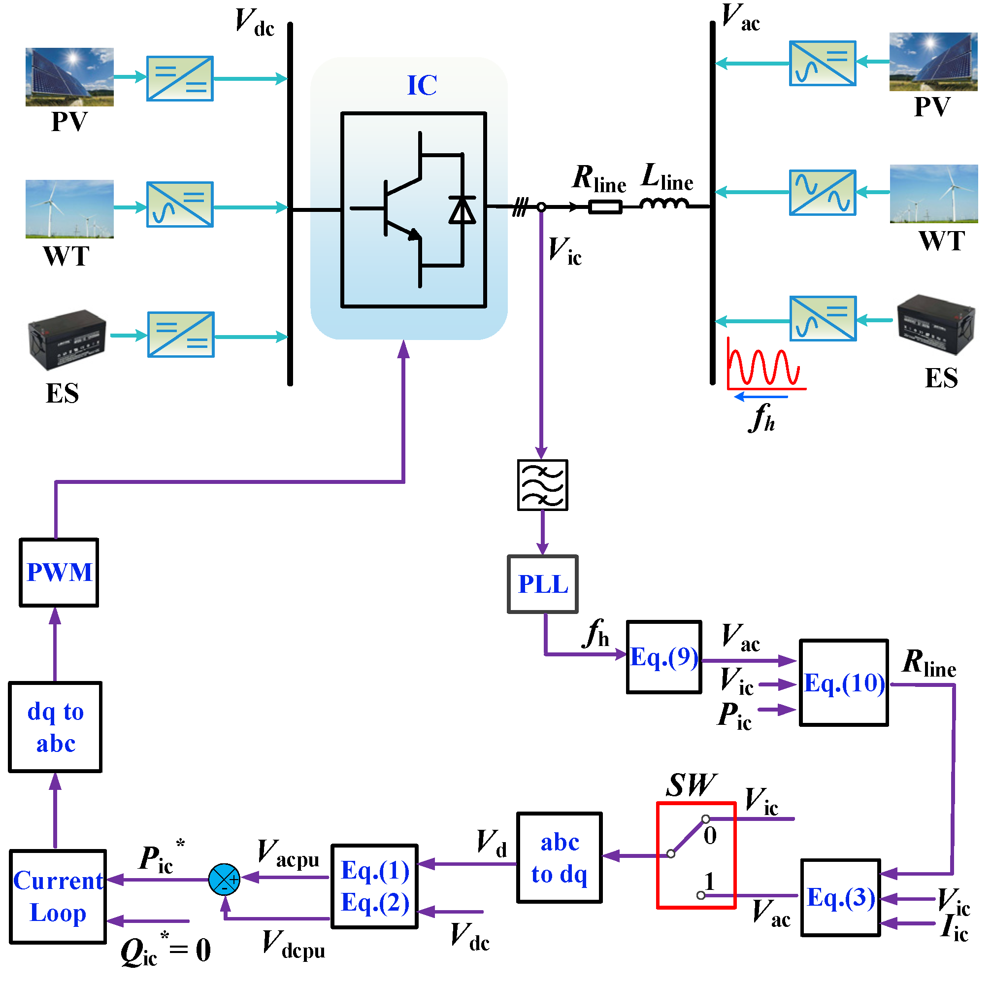
4. Control Strategy of IC Based on Line Impedance Compensation

The proposed control strategy of IC based on line impedance compensation is presented in Figure 4. When the line impedance is negligible, the switch (SW) in Figure 4 can be set to 0 and the system is using Vic as the AC bus voltage. Otherwise, the SW should be set to 1, which means the proposed control strategy is activated.
In order to reliably inject the harmonic signal, the proposed control method utilizes the converter of the energy storage system to inject the small harmonic. After extracting the injected signal by band-pass filter and PLL at the IC side, the AC bus voltage information can be transferred to IC without communication. According to Equation (10), the line resistance can be obtained combining the measured local IC information Vic and Pic. Then, with Equation (3), the line voltage drop can be effectively compensated. The IC is capable of accurately transmitting power between sub-grids according to its reference. Meanwhile, with the proposed control strategy, Vac can be used to monitor the power condition of the AC sub-grid.

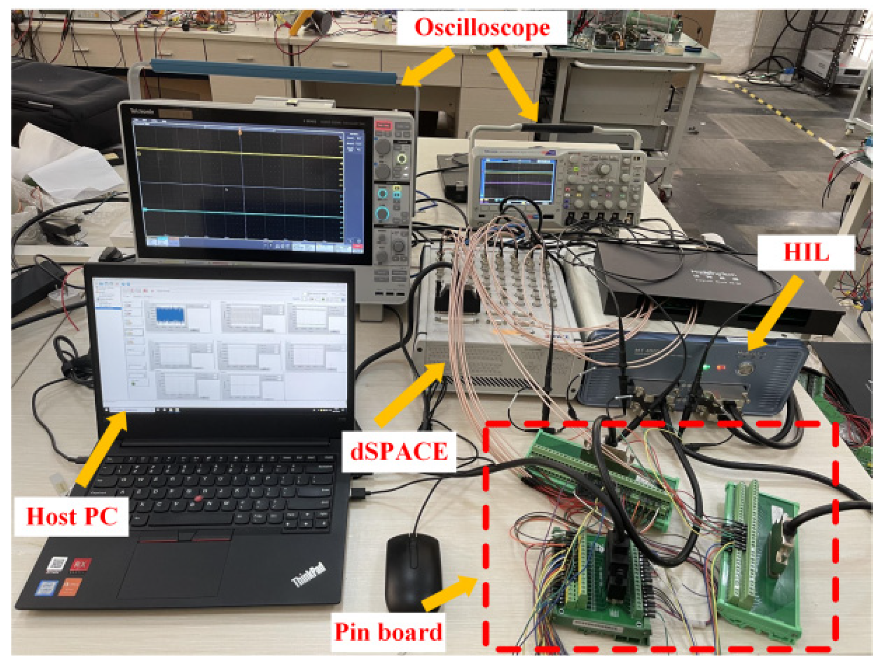
5. Hardware-in-the-Loop (HIL) Verification

5.1. Details of the HIL Platform

To verify the proposed control strategy, real-time simulation platform Starsim is utilized to conduct experiments, and dSPACE is chosen to be the controller. The hybrid AC/DC MG simulation model is established in the Strasim platform. The structure of the simulation model is shown in Figure 4. The entire experimental platform is shown in Figure 5. System parameters are listed in Table 2.
This paper focuses on the active power transmission of the IC of MG, and the following experiments are conducted with the assumption that the reactive power is sufficient in the AC sub-grid, which means that the IC of MG does not need to transmit reactive power. Meanwhile, this paper takes a unified operating condition, that is, the DC sub-grid operates with 5 kW surplus active power and the AC sub-grid deficits the same amount of active power. In order to maintain power balance, the IC should transmit 5 kW from DC side to AC side.

5.2. Case Study

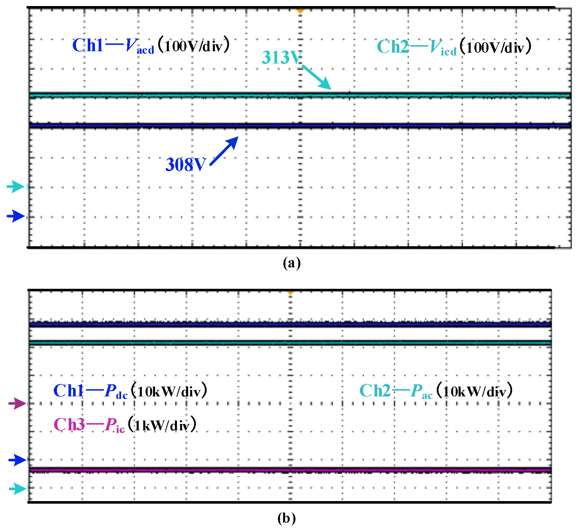
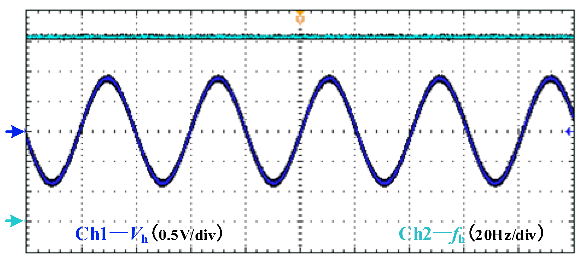
5.2.1. Impact on the Power Quality When Injecting Harmonics

In order to reduce the impact on the power quality of hybrid MG, the magnitude of injected small signal is set to be 0.8 V, which is shown in Figure 6. Fast Fourier Transform (FFT) is used to show the total harmonic distortion (THD) of the AC voltage Vac with or without the injection of the harmonic signal. FFT results are listed in Table 3. Since the injected signal is small, it can be seen that the quality of the AC voltage Vac is barely affected after the injection. The THD increases from 0.05% to 0.56%, which still meets the power quality requirements.

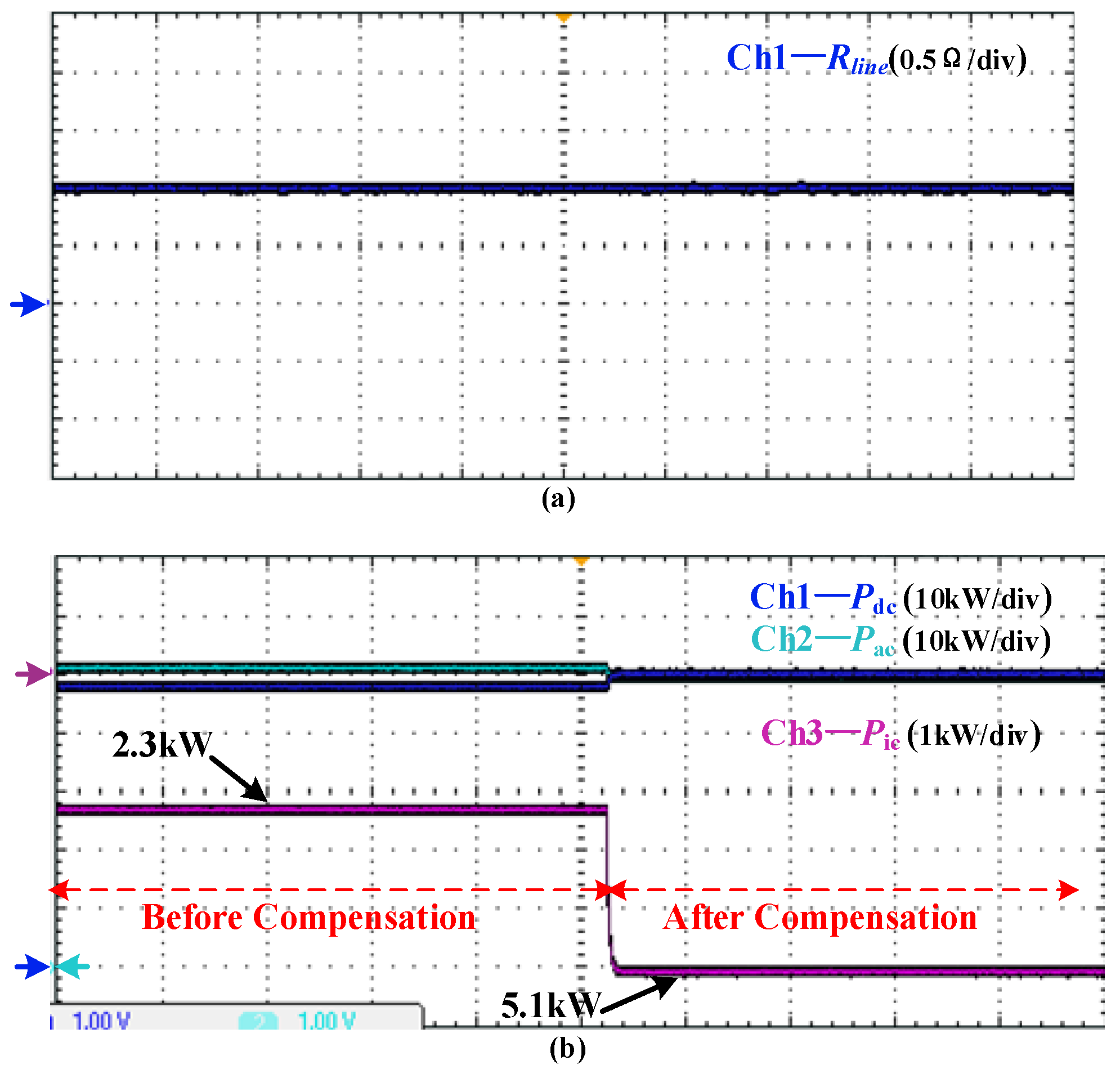
5.2.2. Case 1 (Rline = 1 Ω, Xline = 0 Ω)

When the line impedance is not negligible and the actual Rline is purely resistive (Rline = 1 Ω), as can be seen in Figure 7. It can be seen that with only the local voltage information Vic to control the IC, the transmitted power deviates from its expected value (the IC just transmits 2.3 kW active power from DC sub-grid to AC sub-grid). Figure 7 also shows that large difference exists between the IC local voltage Vic and the AC bus voltage Vac.
In order to solve this problem, a harmonic signal with amplitude voltage 0.8 V is injected to the IC, and the frequency of the injected signal is 123.44 Hz according to Equation (9). With a fifth-order band-pass filter and PLL, the injected signal can be extracted at the IC side, which is shown in Figure 8.
The result of the line resistance estimation and the performance of the compensation strategy are shown in Figure 9. It can be seen that in Figure 9a, the estimated line resistance is in good agreement with its actual value. In Figure 9b, without the compensation method, the IC only transmits 2.3 kW active power, and the AC and DC sub-grids work in overloaded and underloaded state respectively. However, after compensating the voltage drop of the line impedance, Vac can be obtained by the IC and then the IC transmits power 5.1 kW active power from DC sub-grid to AC sub-grid. It should be noted that the extra 0.1 kW is the power loss on the line impedance. After the IC transmits power accurately, both AC and DC sub-grids recover to the rated operation state, which is shown in Figure 9b.

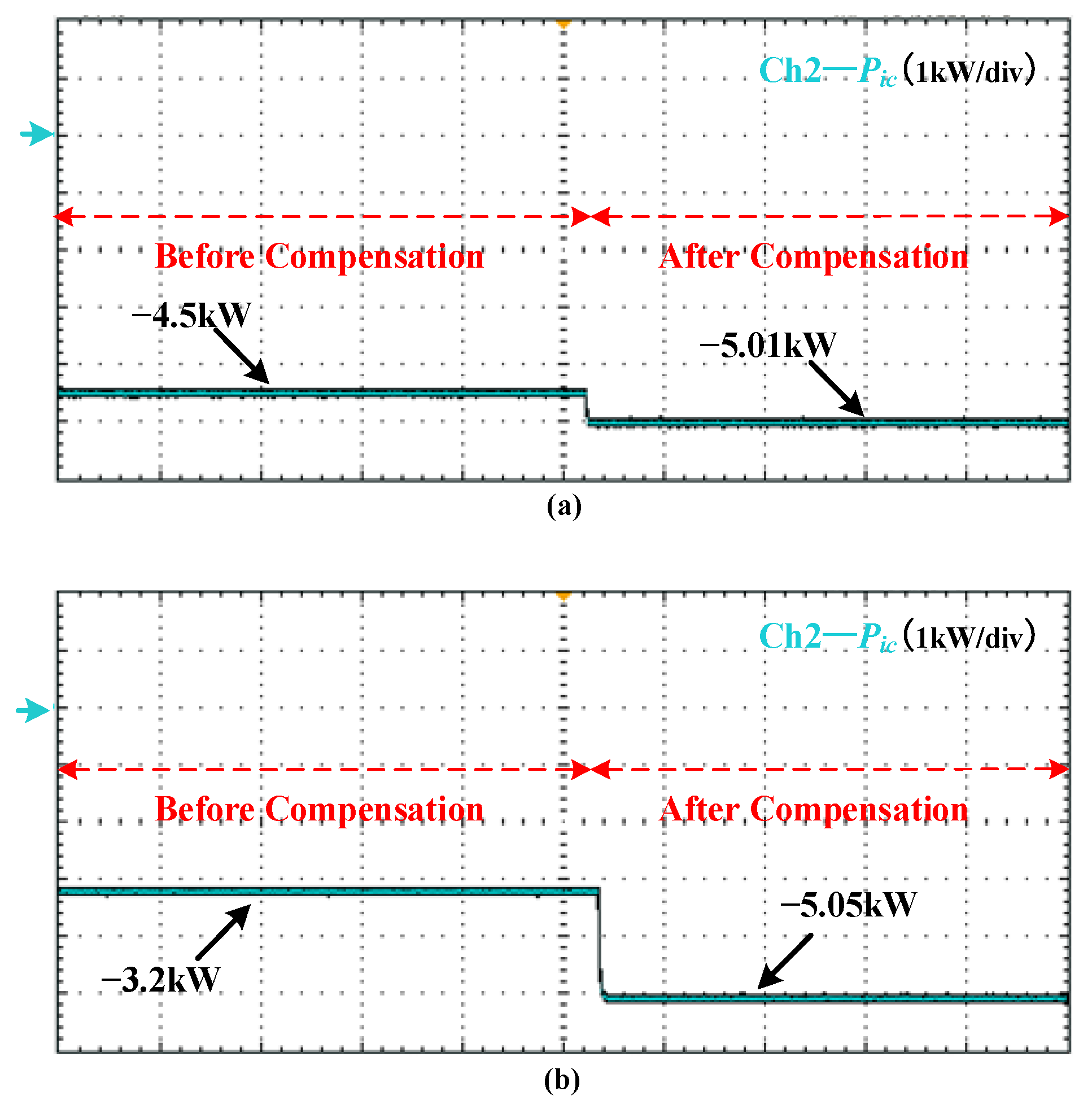
5.2.3. Case 2 (Rline = 1 Ω, Xline = 0.125 Ω)

When the line is a typical one used for low-voltage application as shown in Table 1, taken Rline = 1 Ω and Xline = 0.125 Ω (namely R/X is 8) for an example, the estimation is still accurate. The experimental result is shown in Figure 10.
It can be seen from Figure 10 that since the reactance of low-voltage line is small, there is no obvious influence on the detection of actual impedance and the accurate power transmission between AC and DC sub-grids can be realized with the proposed compensation method.
Compared to the experimental result shown in Figure 9, it is easy to arrive at the conclusion that when the line reactance is considered in low-voltage MG, the compensation method proposed in this paper is still effective.

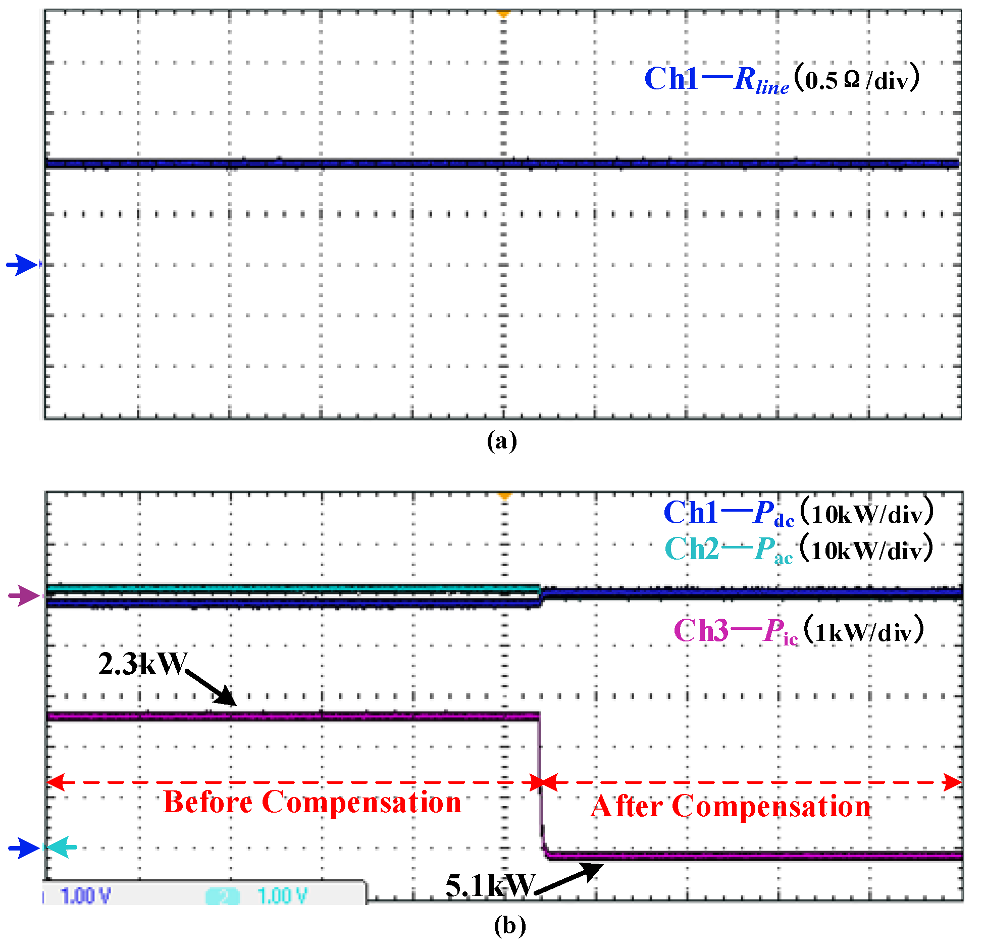
5.2.4. Case 3 (Different Line Resistances)

To further verify the method proposed in this paper, a set of estimation is conducted with actual resistance Rline of 0.1 Ω, 0.5 Ω, 2 Ω, and 5 Ω. The experimental results are shown as followed in Figure 11.
It can be seen from Figure 11 that for different line resistances, the small signal injection method proposed in this paper can accurately obtain its actual value.
Figure 12 shows the IC transmitted power with different line resistances, and the expected power is 5 kW for all cases. It can be seen that without the line voltage compensation method, the larger line resistance is, the greater deviation of the IC transmitted power will be. While with the line voltage compensation method proposed in this paper, the IC with different line resistances can eliminate the power deviation and realize accurate power transmission between AC and DC sub-grids. It needs to be noticed that since the line resistance will inevitably lead to the power loss, the actual power transmission of the IC is slightly greater than its expected value. With the increase of the line resistance, the power loss will rise.

5.3. Discussions about the Results

From the experiment results shown in Section 5.2, it can be concluded that with the assumption that only active power transmission exists in the IC, the small signal injection method can estimate the line resistance precisely. Results show that different transmission line impedance characteristics (resistive or inductive) will not impair the accuracy of the estimated results. Based on the accurate line impedance estimation method, the line voltage compensation strategy proposed in this paper can easily realize accurate power transmission between sub-grids and maintain the power balance of hybrid AC/DC microgrid. However, if the system requires the IC to generate or consume reactive power, the proposed line resistance estimation method will be inevitably with error. Further research is needed to improve the estimation method.

6. Conclusions

Based on line impedance compensation, a control strategy of an interlinking converter in a hybrid microgrid is proposed. With a specified injected small signal, the IC of low-voltage microgrids is able to estimate the line impedance effectively and accurately only using the local information of the IC without the requirements of using communication devices. With accurately calculated AC bus voltage, the line voltage drop can be successfully compensated to achieve the accurate power transmission between AC and DC sub-grids. Simulation and experimental results validate the effectiveness of the proposed compensation method.
The proposed method is effective and accurate with the assumption that reactive power is locally generated or consumed by the local converter of the AC subgrid (in other words, the IC only transmits active power). While when the system needs IC to transfer reactive power, the proposed method will be with calculation error. Further study is required to cope with the ‘IC reactive power issue’ in the future research. Moreover, when the hybrid microgrid needs to apply with multiple ICs running in parallel, further study is also needed to investigate the power sharing ability.

Author Contributions

Conceptualization, C.W. and C.D.; Methodology, C.W.; Software, C.D.; Validation, C.D. and G.L.; Formal analysis, C.D.; Investigation, C.D.; Writing—original draft preparation, C.D.; Writing—review and editing, C.W.; Visualization, G.L.; Supervision, C.W.; Project administration, C.W.; Funding acquisition, C.W. All authors have read and agreed to the published version of the manuscript.

Funding

This research was funded by Shenzhen Science and Technology Innovation Commission Project, grant number JCYJ20210324120404013, GXWD20201230155427003-20200824090345001. The APC was funded by GXWD20201230155427003-20200824090345001.

Institutional Review Board Statement

Not applicable.

Informed Consent Statement

Not applicable.

Data Availability Statement

All data included in this study are available upon request by contact with the corresponding author.

Conflicts of Interest

The authors declare no conflict of interest.

References

  1. Nikkhajoei, H.; Lasseter, R.H. Distributed generation interface to the CERTS microgrid. IEEE Trans. Power Delivery 2009, 24, 1598–1608. [Google Scholar] [CrossRef]
  2. Lasseter, R.H.; Paigi, P. Microgrid: A conceptual solution. In Proceedings of the 2004 IEEE 35th Annual Power Electronics Specialists Conference (IEEE Cat. No.04CH37551), Aachen, Germany, 20–25 June 2004; pp. 4285–4290. [Google Scholar]
  3. Xia, Y.; Wei, W.; Yu, M.; Peng, Y.; Tang, J. Decentralized multi-time scale power control for a hybrid AC/DC microgrid with multiple subgrids. IEEE Trans. Power Electron. 2018, 33, 4061–4072. [Google Scholar] [CrossRef]
  4. Liu, X.; Wang, P.; Loh, P.C. A hybrid AC/DC microgrid and its coordination control. IEEE Trans. Smart Grid 2011, 2, 278–286. [Google Scholar]
  5. Lu, X.; Guerrero, J.M.; Sun, K.; Vasquez, J.C.; Teodorescu, R.; Huang, L. Hierarchical Control of Parallel AC-DC Converter Interfaces for Hybrid Microgrids. IEEE Trans. Smart Grid 2014, 5, 683–692. [Google Scholar] [CrossRef] [Green Version]
  6. Peyghami, S.; Mokhtari, H.; Blaabjerg, F. Autonomous Operation of a Hybrid AC/DC Microgrid with Multiple Interlinking Converters. IEEE Trans. Smart Grid 2018, 9, 6480–6488. [Google Scholar] [CrossRef] [Green Version]
  7. Zhang, B.; Li, D.; Wang, Y.; Yan, X. Self-adaptable reactive power-voltage controller for virtual synchronous generators. J. Eng. 2019, 9, 2969–2973. [Google Scholar] [CrossRef]
  8. Jin, C.; Loh, P.C.; Wang, P.; Mi, Y.; Blaabjerg, F. Autonomous operation of hybrid ac–dc microgrids. In Proceedings of the 2010 IEEE International Conference on Sustainable Energy Technologies (ICSET), Kandy, Sri Lanka, 6–9 December 2010; pp. 1–7. [Google Scholar]
  9. Loh, P.C.; Li, D.; Chai, Y.K.; Blaabjerg, F. Autonomous Operation of Hybrid Microgrid with AC and DC Subgrids. IEEE Trans. Power Electron. 2013, 28, 2214–2223. [Google Scholar] [CrossRef]
  10. Loh, P.C.; Li, D.; Chai, Y.K.; Blaabjerg, F. Autonomous control of interlinking converter with energy storage in hybrid AC–DC microgrid. IEEE Trans. Ind. Appl. 2013, 49, 1374–1382. [Google Scholar] [CrossRef]
  11. Li, X.; Guo, L.; Li, Y.; Guo, Z.; Hong, C.; Zhang, Y.; Wang, C. A Unified Control for the DC-AC Interlinking Converters in Hybrid AC/DC Microgrids. IEEE Trans. Smart Grid 2018, 9, 6540–6553. [Google Scholar] [CrossRef]
  12. Guerrero, J.M.; Berbel, N.; Matas, J.; de Vicuna, L.G.; Miret, J. Decentralized control for parallel operation of distributed generation inverters using resistive output impedance. IEEE Trans. Ind. Electron. 2017, 54, 994–1004. [Google Scholar] [CrossRef]
  13. Zhang, B.; Cao, G.; Ren, C.; Wang, J.; Han, X. Autonomous control strategy of bidirectional AC/DC converter in low voltage hybrid microgrid. In Proceedings of the 12th IEEE Conference on Industrial Electronics and Applications (ICIEA), Siem Reap, Cambodia, 18–20 June 2017; pp. 1564–1569. [Google Scholar]
  14. Xiao, H.; Luo, A.; Shuai, Z.; Jin, G.; Huang, Y. An improved control method for multiple bidirectional power converters in hybrid AC/DC microgrid. IEEE Trans. Smart Grid 2016, 7, 340–347. [Google Scholar] [CrossRef]
  15. Lin, P.; Wang, P.; Jin, C.; Xiao, J.; Li, X.; Guo, F.; Zhang, C. A Distributed Power Management Strategy for Multi-Paralleled Bidirectional Interlinking Converters in Hybrid AC/DC Microgrids. IEEE Trans. Smart Grid 2019, 10, 5696–5711. [Google Scholar] [CrossRef]
  16. Asiminoaei, L.; Teodorescu, R.; Blaabjerg, F.; Borup, U. A digital controlled PV-inverter with grid impedance estimation for ENS detection. IEEE Trans. Power Electron. 2005, 20, 1480–1490. [Google Scholar] [CrossRef]
  17. Asiminoaei, L.; Teodorescu, R.; Blaabjerg, F.; Borup, U. Implementation and test of an online embedded grid impedance estimation technique for PV inverters. IEEE Trans Ind. Electron. 2005, 52, 1136–1144. [Google Scholar] [CrossRef]
  18. Liserre, M.; Blaagjerg, F.; Teodorescu, R. Grid impedance detection via excitation of LCL-filter resonance. In Proceedings of the Fourtieth IAS Annual Meeting. Conference Record of the 2005 Industry Applications Conference, Hong Kong, China, 2–6 October 2005; pp. 910–916. [Google Scholar]
  19. Liserre, M.; Blaabjerg, F.; Teodorescu, R. Grid Impedance Estimation via Excitation of LCL-Filter Resonance. IEEE Trans. Ind. Appl. 2007, 43, 1401–1407. [Google Scholar] [CrossRef]
  20. Ghorbal, M.J.; Ghzaiel, W.; Slama-Belkhodja, I.; Guerrero, J.M. Online detection and estimation of grid impedance variation for Distributed Power Generation. In Proceedings of the 2012 16th IEEE Mediterranean Electrotechnical Conference, Yasmine Hammamet, Tunisia, 25–28 March 2012; pp. 555–560. [Google Scholar]
  21. Ciobotaru, M.; Teodorescu, R.; Rodriguez, P.; Timbus, A.; Blaabjerg, F. Online grid impedance estimation for single-phase grid-connected systems using PQ variations. In Proceedings of the 2007 IEEE Power Electronics Specialists Conference, Orlando, FL, USA, 17–21 June 2007; pp. 2306–2312. [Google Scholar]
  22. Timbus, A.V.; Rodriguez, P.; Teodorescu, R.; Ciobotaru, M. Line Impedance Estimation Using Active and Reactive Power Variations. In Proceedings of the 2007 IEEE Power Electronics Specialists Conference, Orlando, FL, USA, 17–21 June 2007; pp. 1273–1279. [Google Scholar]
  23. Gu, H.; Guo, X.; Wang, D.; Wu, W. Real-time grid impedance estimation technique for grid-connected power converters. In Proceedings of the 2012 IEEE International Symposium on Industrial Electronics, Hangzhou, China, 28–31 May 2012; pp. 1621–1626. [Google Scholar]
  24. Guerrero, J.M.; de Vicuna, L.G.; Matas, J.; Castilla, M.; Miret, J. Output impedance design of parallel-connected UPS inverters with wireless load-sharing control. IEEE Trans. Ind. Electron. 2005, 52, 1126–1135. [Google Scholar] [CrossRef]
  25. He, J.; Li, Y.W.; Guerrero, J.M.; Blaabjerg, F.; Vasquez, J.C. An Islanding Microgrid Power Sharing Approach Using Enhanced Virtual Impedance Control Scheme. IEEE Trans. Power Electron. 2013, 28, 5272–5282. [Google Scholar] [CrossRef]
  26. Engler, A.; Soultanis, N. Droop control in LV-grids. In Proceedings of the 2005 International Conference on Future Power Systems, Amsterdam, The Netherlands, 18 November 2005; pp. 1–6. [Google Scholar]
Figure 1. Typical structure of hybrid AC/DC microgrid.
Energies 15 01664 g001
Figure 2. Schematic diagram of IC.
Energies 15 01664 g002
Figure 3. Voltage phasor diagram.
Energies 15 01664 g003
Figure 4. Control strategy of the IC based on line impendence compensation.
Energies 15 01664 g004
Figure 5. Experimental platform.
Energies 15 01664 g005
Figure 6. Injected signal.
Energies 15 01664 g006
Figure 7. System operation condition without the line impedance estimation (x-axis: time, 1 s/div; y-axis: magnitude of the measured signal): (a) magnitude value of Vac and Vic; (b) output power of sub-grid and IC.
Energies 15 01664 g007
Figure 8. Injected harmonic signal (x-axis: time, 0.004 s/div; y-axis: magnitude of the measured signal).
Energies 15 01664 g008
Figure 9. Experimental results when Rline = 1 Ω (x-axis: time, 1 s/div; y-axis: magnitude of the measured signal): (a) estimated resistance; (b) output power of sub-grids and IC.
Energies 15 01664 g009
Figure 10. Experimental results when Rline = 1, Xline = 0.125 Ω (x-axis: time, 1 s/div; y-axis: magnitude of the measured signal): (a) estimated impedance; (b) output power of sub-grids and IC.
Energies 15 01664 g010
Figure 11. Estimation results of different resistances (x-axis: time, 1 s/div; y-axis: magnitude of the measured signal): (a) Rline = 0.1 Ω; (b) Rline = 0.5 Ω; (c) Rline = 2 Ω; (d) Rline = 5 Ω.
Energies 15 01664 g011aEnergies 15 01664 g011b
Figure 12. Voltage compensation results of different resistances (x-axis: time, 1 s/div; y-axis: magnitude of the measured signal): (a) Rline = 0.1 Ω; (b) Rline = 0.5 Ω; (c) Rline = 2 Ω; (d) Rline = 5 Ω.
Energies 15 01664 g012aEnergies 15 01664 g012b
Table 1. Typical line parameters of different voltage [26].
Type of LineR (Ω/km)X (Ω/km)R/X
Line for the low-voltage0.6420.0837.7
Line for the medium-voltage0.1610.1900.85
Line for the high-voltage0.060.1910.31
Table 2. Main parameters of system.
SubsystemParameterValue
AC sub-gridRated power PacN50 kW
RMS rated voltage (phase to ground)220 V
Droop coefficient mac0.002 V/W
Filter capacitance220 μF
Filter inductance5 mH
ICCapacitor on DC side4700 μF
Filter inductance3 mH
DC sub-gridRated power PdcN50 kW
Rated voltage700 V
Droop coefficient mdc0.002 V/W
Table 3. FFT analysis of the impact of the injection.
THD (%)Vacd (V)
Before injection0.05308
After injection0.56308
Publisher’s Note: MDPI stays neutral with regard to jurisdictional claims in published maps and institutional affiliations.

