1. Introduction
Distributed generation is an emerging trend in a generation whereby electricity is produced close to the load to meet the local power requirement, and the generator is connected to the transmission or distribution line to export excess power.
One of the important differences between distributed, conventional, and stand-alone generations resides in the way generating units are controlled. In both conventional and stand-alone generations, generating units are controlled to maintain the system frequency and the bus voltage within prescribed limits [
1,
2]. This control method is not applied in distributed generation in order to avoid steady state and transient stability issues and to make islanding detection possible. In a distributed generation, generating units are operated to maintain the output active and reactive powers constant irrespective of network frequency or voltage changes. Power factor control is often used. The governor controls the input steam flow of a turbine generator so that it supplies constant optimal active power while the automatic voltage regulator (AVR) controls the reactive power to maintain the power factor constant. Hence, distributed generation does not participate in frequency or voltage control in network-connected mode. These functions are only activated in islanding mode when the generator operates like a stand-alone generation.
Connecting distributed generation to an existing network may pose several problems. Islanding is the most serious problem posed by distributed generation [
3]. Currently, distributed generation interconnection standards preclude unintentional islanding operation that includes utility loads. They recommend that when islanding occurs, the distributed generation installation must be disconnected from the utility network at the point of common coupling (PCC) [
4]. This leaves the local load on the island but removes the utility loads.
Distributed generation improves the supply reliability of the host installation by reducing the number and the duration of interruptions if the distributed generator is allowed to island on the local load and operate as a backup supply during islanding [
5]. However, transient torques generated at the moments of islanding and removing the utility load from the island will inflict shaft fatigue life loss when they exceed the shaft endurance limit and lead to early fatigue damage [
6]. Therefore, it is important to protect the shafts of a distributed turbine generator against early fatigue damage to ensure a safe and reliable islanding operation.
Current research on distributed generation mainly focuses on other issues of islanding while shaft protection is not addressed, and therefore, it constitutes the gap in this field. This paper proposes a two-step shaft protection approach for distributed generation turbine generators. The first step is an operating practice to mitigate the torsional vibrations induced by the transient torques and avoid shaft fatigue life loss during islanding. The second step is a backup to the first step. It is based on detecting the risk of shaft fatigue damage, which occurs when the actual shaft torque exceeds a critical value following the removal of the utility load from the island. The turbine generator is shut down to prevent islanding on the local load in this situation. Conversely, islanding on the local load is allowed when the actual shaft torque is smaller than the critical torque.
This paper also investigates the possibility of using a typical online monitoring and protection system (OMPS) [
7], also referred to as a torsional stress analyzer (TSA) by Joyce et al. [
8], to protect the shafts. OMPSs are commonly used to protect the shafts of central power station turbine generators against cumulative fatigue damage. An OMPS is normally designed to operate as a backup to torsional vibrations mitigation to shut down the turbine generator when the accumulated fatigue life loss reaches a dangerous level. The ability of OMPSs to protect the shafts against cumulative fatigue damage due to moderate transient torques was established in the work of [
8,
9,
10], but their ability to protect the shafts against abrupt fatigue damage due to huge torque impulses has never been established. Indeed, a huge torque impulse may cause shaft damage in less than a full cycle of the torque waveform, almost instantly, before even the OMPS can estimate the fatigue life loss incurred by the shaft since OMPSs evaluate shaft fatigue life loss based on complete cycles of the torque waveform, according to the rain-flow cycle counting technique [
8]. According to Liu et al. [
11], the inability of OMPSs to capture torque impulses timely is mainly due to the long response time of the signal processing methods or filters. These researchers also stated that OMPSs have the following drawbacks: They do not evaluate shaft fatigue life loss accurately because of the lack of a cause-to-effect relationship between the turbine generator operating quantities and shaft fatigue life loss. They can disconnect the turbine generator incorrectly due to the stringent setting of trip points to avoid shaft fatigue damage.
A question arises then of whether an OMPS can be used to protect the shafts of a distributed generation turbine generator against fatigue damage due to islanding, considering that a huge impulse torque may be generated during islanding, particularly at the moment of removing the utility load from the island.
Computer simulation is used in the study because practical estimation of turbine generator shaft fatigue life loss is always based on computer simulation [
9,
10]. The process requires first obtaining the shaft torque waveform. It entails the use of a shaft assembly model, fatigue model, cycle counting technique, and linear accumulation theory.
The proposed protection method is implemented and simulated in PSCAD version 4.5. Results show that the proposed protection method ensures islanding operation without endangering the shafts. A comparative study of shaft fatigue life loss shows that the proposed protection method only yields 0.011% shaft fatigue life loss under the most adverse islanding condition against 100% obtained when no protection or when a typical OMPS is used. These results show that it is unsafe to operate a distributed generation turbine generator without shaft protection and that an OMPS is not suitable for islanding protection.
Section 1 introduced the concepts of islanding of distributed generation and fatigue damage of turbine generator shafts due to transient torques.
Section 2 presents a critical review of published literature on the calculation of turbine generator shaft torque.
Section 3 presents the methods and materials used in this study.
Section 4 discusses an operating practice to mitigate shaft torsional vibrations caused by the islanding of a turbine generator. Shaft transient torque during islanding is modeled in
Section 5, and the protection method is developed in
Section 6.
Section 7 discusses the protection process. This is implemented and simulated in
Section 8 using PSCAD version 4.5. Recommendations for the safe operation of distributed generation turbine generators are presented in
Section 9, and conclusions are drawn in
Section 10.
2. Related Work
Accurate calculation of shaft torque is an important aspect of shaft fatigue life loss evaluation. The challenge in this regard emanates from the difficulty in quantifying the cause of torsional vibration and the complexity of the related differential equations. These equations are nonlinear and coupled. The solution to these equations was approached in different ways:
Liu et al. [
12] expressed the electromagnetic torque as a time function, applied this function to the shaft assembly model, and then used numerical methods to solve the resulting differential equations for shaft torque. This method does not represent the two-way interaction between the electromagnetic torque and the shaft assembly and is suitable for offline calculations. Tsai et al. [
13], Liu et al. [
14], Chyn et al. [
15], and Volkanovski et al. [
16] modeled the network comprising the transmission lines, transformers, generators, turbines, etc. then used simulation to evaluate shaft torque. Liu et al. [
14] coupled torsional vibrations of the shaft assembly back to the electromagnetic torque to represent the two-way interaction between the two. Ramey et al. [
17], Agrawal et al. [
18], and Yang et al. [
19] applied the steam torque and the electromagnetic torque to the spring-mass model of the shaft assembly, then solved the system of differential equations obtained for shaft torque. This method does not represent the two-way interaction between the electromagnetic torque and the shaft assembly, and damping is difficult to represent. Chen and al. [
9] obtained the electromagnetic torque from the measured current and voltage, applied this to the spring-mass model of the shaft assembly then used real-time simulation to determine shaft torque. The shaft torsional angle was then coupled back to the electromagnetic torque. This method represents electrical and mechanical damping and the two-way interaction between the electromagnetic torque and the shaft assembly.
Aspragathos et al. [
20] and Jackson et al. [
21] investigated the effect of modeling the interaction between the generator’s electromagnetic torque and the shaft assembly on the accuracy of the shaft response and found that for the analysis of transient torques, the one-way modeling (i.e., the electromagnetic torque excites the shaft assembly but the effects of the shaft assembly torsional vibrations on the electromagnetic torque are not modeled) yielded satisfactory results. According to this study, two-way modeling is only important for the analysis of subsynchronous resonance.
Luo et al. [
22] used a two-degrees-of-freedom model of the shaft assembly to study the effect of short circuit clearing time on shaft torque amplification in a series-compensated network, while Park et al. [
23] used this model to study the effect of circuit breaker reclosing on shaft transient torque. Moreover, Yang et al. [
19] showed that reduced models could provide suitable accuracy for low-order torsional modes.
While these approaches simplify the calculation of shaft torque, they all do not relate the network operating parameters to shaft fatigue life loss. According to Liu et al. [
11], this is a problem because the protection system will not be able to evaluate shaft fatigue life loss accurately.
A two-degrees-of-freedom model of the shaft assembly is used in this paper to simplify the solution of differential equations. The one-way modeling of the interaction between the electromagnetic torque and the shaft assembly is used since subsynchronous resonance is not involved in the study. The novelty of the approach followed in this paper is that a relationship between network operating parameters, shaft torque, and the onset of shaft fatigue life loss is established. In this way, the protection system can monitor the shaft torque to predict the risk of shaft fatigue damage. The limitation of the approach is that damping cannot be modeled accurately.
Table 1 summarizes the different approaches to simplify the calculation of shaft torque.
3. Methodology
A case study (case study 1) is first used to develop the protection method. Case study 1 uses a turbine generator connected to a network model and operates as a distributed generator. The protection method is then implemented and simulated in four case studies (case studies 2 to 5) in order to evaluate its effectiveness.
Section 3.1 describes the network model. The methodology to estimate shaft fatigue life loss is set out in the work of [
24].
Section 3.2 presents the methodology to model shaft transient torque during islanding, while
Section 3.3 describes the simulation process.
3.1. Description of the Network Model
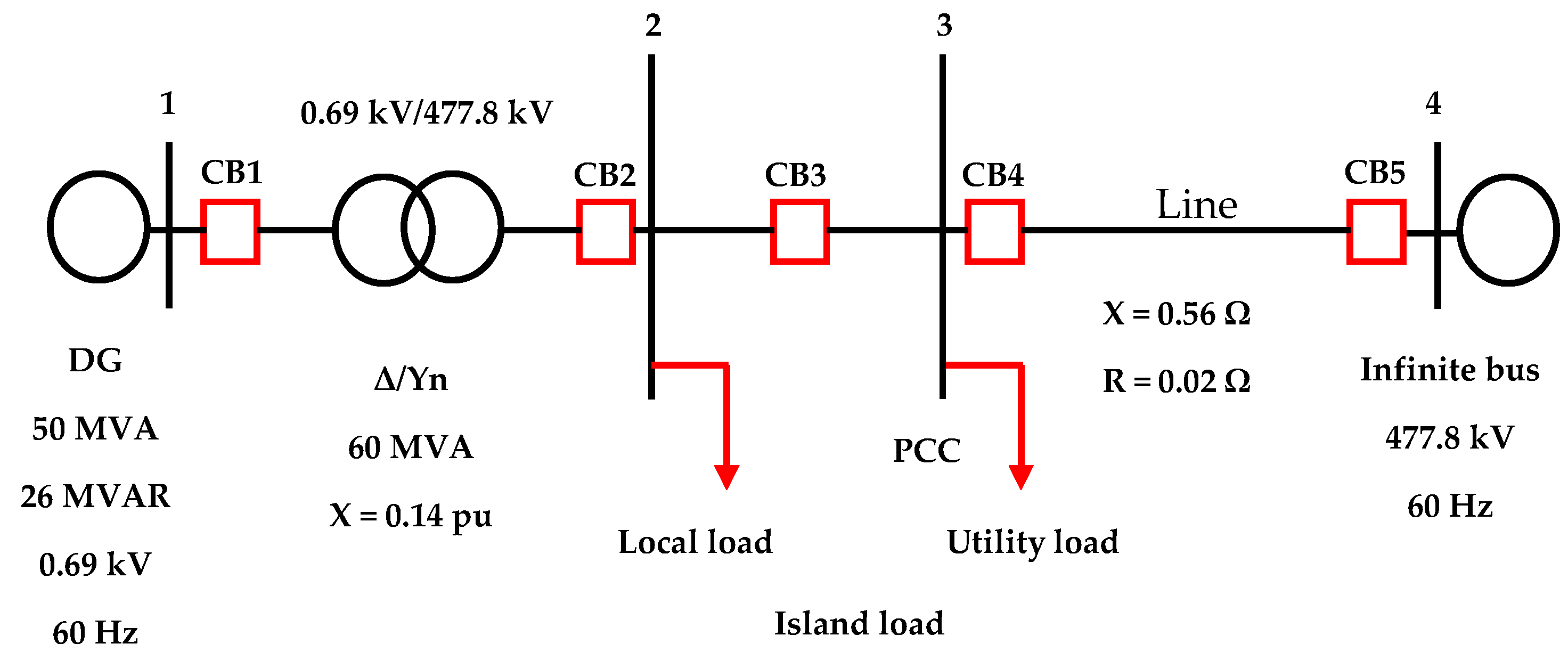
Case study 1 network model is shown in
Figure 1. The island load is made up of the local load and a portion of the utility load. The normal frequency operating range of the network is 59–61 Hz, and the normal voltage operating range is 0.9–1.1 pu [
4]. Islanding is simulated by opening circuit breaker CB4. An islanding detection relay that is connected at the PCC opens circuit breaker CB3 when it detects the islanding. This removes the utility load from the island and causes the turbine generator to island on the local load and operate as a backup supply. The turbine generator operates with power factor control in network-connected mode and switches to frequency and voltage control in islanded mode. Both the automatic voltage regulator (AVR) and the governor are capable of these control methods.
The turbine generator shaft assembly is represented with the spring-mass model of
Figure 2 [
24].
It consists of the following: high-pressure turbine (HP), intermediate-pressure turbine (IP), low-pressure turbine A (LPA), low-pressure turbine B (LPB), generator (GEN), exciter (EXC), spring constant (K), and damping constant (D). The steady-state torque is shared among turbine cylinders in this manner. HP: 30%, IP: 26%, LPA: 22%, LPB: 22%. The data for the spring-mass model are given in
Table 2.
The dynamics of the shaft assembly are defined by (1):
where
J is the matrix of rotor moments of inertia (kgm
2),
, the matrix of damping constants (joule-s/rad or watt-s
2/rad),
, the matrix of spring constants (joule/rad or watt-s/rad),
, the vector of input torques (Nm),
, and
, respectively the vectors of angular displacements (rad), angular speeds (rad/s), and angular accelerations (rad/s
2). The synchronous generator data are given in
Table 3.
3.2. Determining the Critical Torque
The critical torque is defined as the shaft torque above which torsional vibrations during islanding become undamped. It is lower than the shaft endurance limit and is considered as the threshold to shut down the turbine generator to avoid the risk of shaft fatigue damage due to undamped torsional vibrations.
An important step in determining the critical torque is to mathematically formulate the shaft torque at the moment of removing the utility load from the island. The following approach is adopted in this paper to simplify the solution of equations (1). First, the transient electromagnetic torque is modeled. This is considered as the forcing function, which is applied to a two-degrees-of-freedom model of the shaft assembly considering only the generator and the low-pressure-B rotors (i.e., considering only the LPB-GEN shaft), as shown in
Figure 3. The effect of the shaft assembly torsional vibration on the transient electromagnetic torque is not represented.
Modal analysis is applied to determine rotor angles θ1 and θ2. The critical torque is obtained by substituting the critical load value in the mathematical expression of shaft transient torque. The critical load is the value of the local load that is required to damp the transient torque below damaging levels. It is determined during the fatigue study.
3.3. Implementation and Simulation of Shaft Protection
The protection method is implemented in PSCAD Version 4.5 in order to evaluate its effectiveness. The fundamental question is whether the turbine generator does not incur shaft fatigue life loss during islanding. First, four case studies (case studies 2 to 5) are defined. The transient torque exceeds the critical torque in case studies 2 to 4 and poses a risk of shaft fatigue damage during islanding. Torsional vibration mitigation is insufficient for these cases. The local load is zero in case study 3. This is a case of absence of torsional vibrations mitigation, and the risk of abrupt shaft damage is the highest. There is no risk of shaft fatigue damage in case study 5. Torsional vibrations mitigation is sufficient for this case. Secondly, islanding is simulated for the four cases. The purpose of the simulations is to generate shaft torque waveforms to be used to estimate shaft fatigue life loss. Islanding is detected within 0.5 s by a communication-based relay and the utility load is removed from the island immediately. The performance of the proposed protection method is compared with that of a typical OMPS and no protection in the four cases. The turbine generator is shut down when the accumulated shaft fatigue life loss reaches 10% to simulate the OMPS. The operation of the turbine generator is unrestricted in the case of no protection.
The data of the systems used are given below. The electrical network model is the same as that of
Figure 1.
The spring-mass model data for case studies 2 and 4 are given in
Table 4.
The steady-state torque is shared among turbine cylinders in this way: HP: 31%, LPA: 34.5%, LPB: 34.5%.
The spring-mass model data for case studies 3 and 5 are given in
Table 5.
The steady-state torque is shared among turbine cylinders in this way: HP: 27.8%, IP: 35.8%, LPA: 18.2%, LPB: 18.2%.
4. Torsional Vibration Mitigation
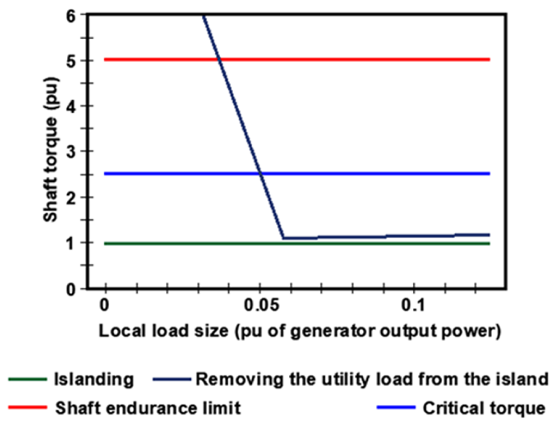
Figure 4 shows the torques of the LPB-GEN shaft of case study 1 at the moments of islanding and removing the utility load from the island. The turbine generator supplies 0.82 pu power. The total island load is 0.67 pu, and it is constant, but the local load portion of it increases (while the utility load portion decreases). It is seen that the torque induced at the moment the utility load is removed from the island can be much higher than the shaft endurance limit when the local load is zero and decrease as the local load increases. There is a value of the local load where this torque falls below the shaft endurance limit. As the local load continues to increase, a value is reached (0.05 pu in
Figure 4) where the torque waveform becomes damped. Let this value of the local load be called the critical load, and the corresponding peak shaft torque be called the critical torque. When the local load is bigger than the critical value, shaft torques are damped below the critical torque and hence may not inflict fatigue life loss, but when the local load is smaller than the critical value, shaft torques are undamped and will inflict fatigue life loss when they exceed the shaft endurance limit. In particular, when the local load is zero, the transient torque will damage the shaft instantly after the utility load is removed from the island. This case shows that the local load can be used to damp torsional vibrations during islanding and avoid shaft fatigue life loss.
5. Modeling Shaft Torque
5.1. Modeling the Forcing Function
The following must be considered when modeling the forcing function. First, the mechanical input torque to the generator rotor (T
m) is strictly constant since the turbine generator operates with constant power factor control. Secondly, when islanding occurs and when the utility load is removed from the island, the generator electromagnetic torque (T
e) changes suddenly to match the load. Hence, the forcing function may be expressed with the torque relation of (2).
The torque relation may be transformed into a power relation by multiplying and dividing both sides by ωs, the synchronous angular speed. This simplification neglects speed and induced voltage changes since the utility load is removed from the island within a narrow range of frequency or voltage change. Further simplification is made by neglecting generator losses. Therefore, the forcing function may be expressed as a step change in the generator electromagnetic torque or output power.
At the moment of islanding:
At the moment of removing the utility load from the island:
All powers in (3) and (4) are defined prior to islanding and are expressed in MW. Pgen is the generator output power, Pl is the local load size, and Pu is the utility load size.
5.2. Modeling Shaft Transient Torque
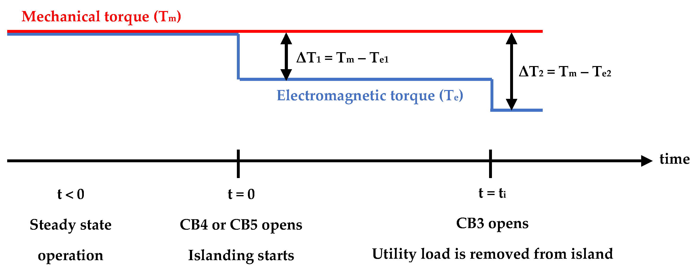
The timeline of events is shown in
Figure 5. Before islanding, the system operates in steady state. It steps into a transient state when islanding occurs and continues to operate in this state until after the utility load is removed from the island when a new steady state is reached. The shaft torque developed in this paper is only valid in close vicinity of this point.
The generator rotor and the LPB rotor in
Figure 3 rotate in phase while maintaining a constant angle with respect to the infinite bus voltage phasor during steady state (t < 0). Hence the equations
Equation (7) defines shaft dynamics at the moment of islanding (t = 0).
The natural vibration frequency is given by (8).
Equation (9) defines shaft dynamics at the instant the utility load is removed from the island (t = t
i).
Shaft torque at the moment of removing the utility load from the island is now obtained per unit of the base torque, T
b.
where T
m is the per-unit steady-state mechanical torque.
6. Proposed Protection Method
The proposed protection method is implemented in two steps. The first step is an operating practice to mitigate torsional vibrations and avoid shaft fatigue life loss during islanding. The second step is a backup to the first step. It consists in predicting the risk of shaft fatigue damage by comparing the LPB-GEN shaft torque with the critical torque in the period after the utility load is removed from the island and declaring a risk of shaft fatigue damage when the LPB-GEN shaft torque exceeds the critical torque. If the LPB-GEN shaft torque is bigger than the critical torque, the turbine generator risks shaft fatigue damage and should be shut down (steam flow closed) immediately. This prevents islanding on the local load. Conversely, the turbine generator should be allowed to island on the local load if the LPB-GEN shaft torque is smaller than the critical torque because this situation implies that the islanding operation is safe since shafts will not incur fatigue life loss.
It was shown in the work of [
24] that shaft fatigue life loss during islanding is avoided when the size of the local load is at least 5% of the generator output power when ΔP
1 > 0, or at least 10% when ΔP
1 < 0. The size of the local load required to avoid shaft fatigue life loss during islanding was called the critical load value and the corresponding torque, the critical torque. Equation (11) expresses the load condition to avoid shaft fatigue life loss during islanding.
where k is the safety factor. Its value is determined by the critical load value and must be in the following ranges to avoid shaft fatigue life loss during islanding: 0.05 ≤ k ≤ 2.7 when ΔP
1 > 0 or 0.1 ≤ k ≤ 1.8 when ΔP
1 < 0. Equation (11) is the operating practice to mitigate torsional vibrations during islanding.
Substituting (11) in (10) yields the critical torque, which is the maximum value of the time function between the accolades. The positive sign in front of the third term corresponds to the case where P
l > P
gen and the negative sign to the case where P
l < P
gen. For given values of ΔP
1, t
i, P
gen, k, and T
m, the critical torque is constant and can be denoted T
cr.
Shaft protection is accomplished by a protection logic that sends a trigger signal to the control modules of the turbine generator steam valves according to (13), where trigger (t) = 1 means close the steam valves and trigger (t) = 0 means refrain.
Closing the steam valves when trigger (t) = 1 shuts down the turbine generator to disallow islanding on the local load while leaving them open when trigger (t) = 0 allows islanding on the local load to proceed.
The second condition of (13) can only be realized when torsional vibrations mitigation is insufficient or inexistent, and thus, it is a backup to torsional vibrations mitigation.
Although the forcing function could be modeled more accurately as a sawtooth, this approach would make it difficult to define a safe trip point. Modeling it as a step function maintains a suitable accuracy and allows the critical torque to be represented as a line of constant torque in time, located below the line of shaft endurance limit, which the LPB-GEN shaft torque should not exceed. The height of the critical torque line is adjustable. It is affected by the operating conditions in (12) but mostly by the steady-state torque. This means that the protection system always adapts to operating conditions to determine the correct trip point. Parameter Tm in (12) can also be seen as an independent input that can be used to adjust the trip point.
7. Flowchart of the Protection Process
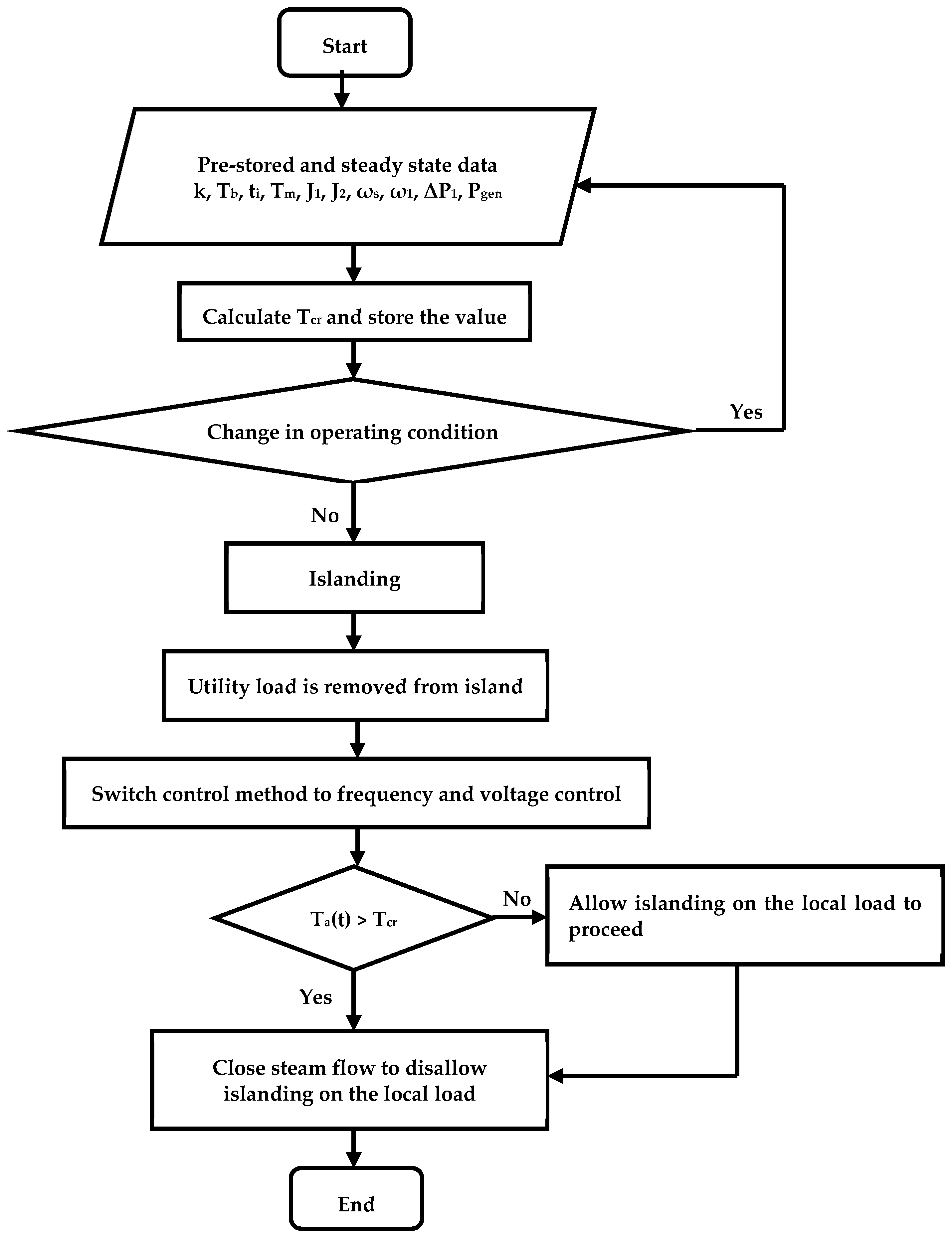
Figure 6 shows the main steps of the protection process.
The values of the following parameters are pre-stored in the protection system. Base torque (Tb), moments of inertia (J1 and J2), synchronous angular frequency (ωs), and natural vibration frequency (ω1). Safety factor (k) is a manual entry into the protection system. The generator output power (Pgen) and the steady-state torque (Tm) are measured from the turbine generator. Other parameter values are calculated during steady-state operation and saved in the system. The time to remove the utility load from the island (ti) is determined based on the islanding detection method used. The sudden power change (ΔP1) is calculated from the power supplied by the turbine generator and the network and the power absorbed by the loads. The critical torque (Tcr) is then determined from (12). This value is updated whenever there is a change in operating conditions. The LPB-GEN shaft torque (Ta (t)) is compared with the determined critical torque after the utility load is removed from the island. If it is bigger than the critical torque, the turbine generator is shut down, and islanding on the local load is disallowed; else, islanding on the local load is allowed to proceed. The control method is switched from power factor control to frequency and voltage control immediately after the utility load is removed from the island. The size of the local load is also curtailed to the rated turbine generator output power at this moment.
8. Implementation and Simulation
8.1. Description of the Simulation Setups
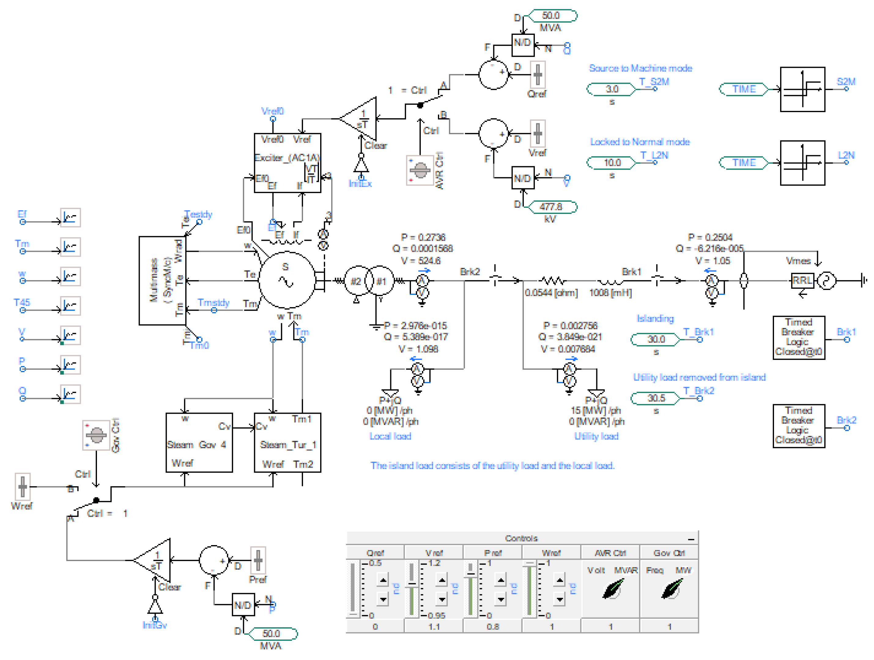
The protection method was implemented and simulated in PSCAD version 4.5. There are two simulation setups, one for the electrical network and the other for the protection system. The electrical network setup is shown in
Figure 7.
The main features are the transmission network represented by a voltage source, the sub-transmission line, the loads, the synchronous generator, the transformer, the circuit breakers, and a multimass block to represent the turbine generator shaft assembly. The synchronous generator exciter (Exciter_AC1A) incorporates an AVR. The turbine (Steam_Tur_1) is equipped with a thermal governor (Steam Gov 4). The load is split into two to represent the local load and the utility load. Islanding is initiated when a timed breaker logic opens circuit breaker Brk1. The utility load is removed from the island when another timed breaker logic opens circuit breaker Brk2. The turbine generator operates in power factor control in network-connected mode and switches to frequency and voltage control in islanded mode. The switching is executed by switches Gov Ctrl and AVR Ctrl after the utility load is removed from the island. Closing the steam valves is simulated by setting the speed reference (wref) on the turbine and governor to zero.
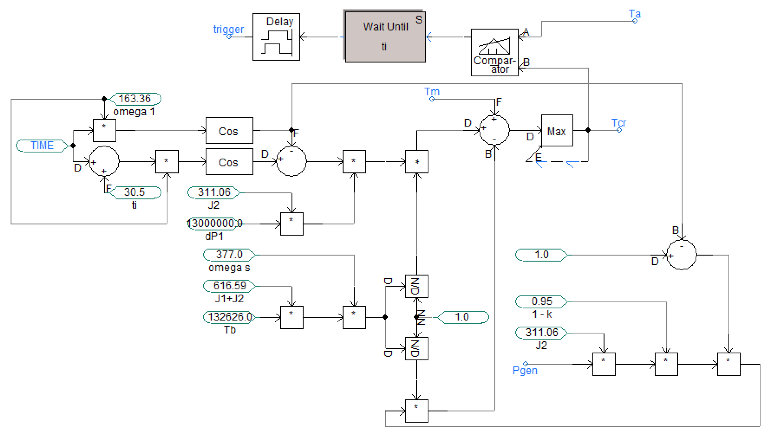
The setup for the protection system is shown in
Figure 8. This stage of the protection system receives the following data as inputs: the safety factor (k), the base torque (Tb), the time to remove the utility load from the island (ti), the steady-state mechanical torque (Tm), the generator rotor and low-pressure-B rotor inertia constants (J1 and J2), the synchronous angular speed (omega s), the natural vibration frequency (omega 1), the sudden power change at islanding (dP1), and the steady-state turbine generator output power (Pgen). It uses these data to calculate the critical torque (Tcr), which it then inputs into the protection logic. This logic also receives the LPB-GEN shaft torque (Ta) as an input. It compares the two inputs and outputs a trigger signal according to (13).
8.2. Results and Discussion
Results of simulation and estimation of shaft fatigue life loss are presented in
Table 6.
The first four columns on the left define the conditions prevailing in each case study. The fatigue life losses presented in this table are those incurred by the most stressed shaft. Islanding on the local load is not allowed when there is a risk of shaft fatigue damage (case studies 2 to 4), but it is allowed when there is no risk of shaft fatigue damage (case study 5). The proposed protection method yields 0.011% shaft fatigue life loss in the most adverse condition (case study 3). This is a much smaller value compared to the 100% shaft fatigue life loss obtained when the OMPS or no protection is used. The proposed protection method yields no shaft life loss in case study 4, but the OMPS yields 2.8% shaft fatigue life loss.
Figure 9 shows the torques obtained during the simulation of case study 3 in the absence of shaft protection. Islanding starts at 30 s, and the utility load is removed from the island at 30.5 s. The LPB-GEN shaft torque impulse reaches a value of 2.5 times the shaft endurance limit in less than a full cycle of the torque waveform and poses a high risk of abrupt fatigue damage. The OMPS is unable to protect the shafts for this case, but the proposed protection method performs well. This is because it does not wait for the transient torque to exceed the shaft endurance limit or the accumulated fatigue life loss to reach a dangerous level.
Figure 10 shows the torques obtained during the simulation of case study 5 in the absence of shaft protection. Islanding starts at 30 sec, and the utility load is removed from the island at 30.5 s. It can be seen that the LPB-GEN shaft torque does not exceed the critical torque after the utility load is removed from the island and torsional vibrations damp. This is why islanding on the local load is allowed for this case.
9. Recommendations
A distributed generation turbine generator may not be operated with power factor control in islanded mode because this will lead to undamped torsional vibrations, which could damage the shafts in the event of a disturbance. Instead, the control method should be switched to frequency and voltage control.
A distributed generation turbine generator shall not be disconnected from the network at its terminals or at the attached transformer’s terminals because this will cause severe torsional vibrations, which may damage the shafts. Instead, a distributed generation turbine generator shall be disconnected from the network in such a way that a load equal to at least 10% of the turbine generator output power, as determined during network-connected mode, stays attached to it until it comes to a standstill.
A distributed generation turbine generator may not be operated without shaft protection. The proposed protection method offers a solution in that regard. Its implementation in existing and future installations should be considered. However, a typical OMPS is not recommended.
Suspected cases of shaft fatigue life loss due to a failed protection following islanding should always be investigated. The following data will be required besides torsional and fatigue data from the manufacturer:
- (1)
The islanding commencement time and the time when the utility load was removed from the island;
- (2)
The turbine generator output power prior to islanding;
- (3)
The size of the local load prior to islanding;
- (4)
The power supplied or absorbed by the distributed generation installation prior to islanding.
To ensure speedy shaft protection during islanding, a distributed generation turbine generator shall be equipped with intercept valves.
10. Conclusions
Successful islanding operation of a distributed generation turbine generator requires a protection system to protect the shafts against the transient torques generated at the moments of islanding and removing the utility load from the island. A typical OMPS may not fulfill this function satisfactorily due to its inability to capture torque impulses timely. The key features of an appropriate protection system are the ability to protect the shafts against abrupt fatigue damage due to huge torque impulses and the ability to avoid the accumulation of shaft fatigue life loss due to moderate shaft transient torques because islanding may happen several times during the service life of the turbine generator.


