Abstract
Gas turbine intake air cooling (TIAC) by exhaust gas heat recovery chillers is a general trend to improve turbine fuel efficiency at increased ambient temperatures. The high efficiency absorption lithium–bromide chillers of a simple cycle are the most widely used, but they are unable to cool inlet air lower than 15 °C. A two-stage hybrid absorption–ejector chillers were developed with absorption chiller as a high temperature stage and ejector chiller as a low temperature stage to subcool air from 15 °C to 10 °C and lower. A novel trend in TIAC by two-stage air cooling in hybrid chillers has been substantiated to provide about 50% higher annual fuel saving in temperate climate as compared with absorption cooling. A new approach to reduce practically twice design cooling capacity of absorption chiller due to its rational distribution with accumulating excessive refrigeration energy at decreased thermal loads to cover the picked demands and advanced design methodology based on it was proposed. The method behind this is issued from comparing a behavior of the characteristic curves of refrigeration energy required for TIAC with its available values according to various design cooling capacities to cover daily fluctuation of thermal loads at reduced by 15 to 20% design cooling capacity and practically maximum annual fuel reduction.
1. Introduction
A thermodynamic efficiency of all the combustion engines falls with increasing inlet air temperature: electric power drops and specific fuel consumption grows [1,2]. The combustion gas turbines (GT) are especially sensible to ambient air temperature at the inlet [3,4]. Therefore, it is quite reasonable to convert the heat of exhaust gas to refrigeration for intake air cooling [5,6]. The general trend in enhancing the fuel efficiency of GT at increased ambient air temperatures is turbine intake air cooling (TIAC) by exhaust heat recovery chillers [7,8]. The exhaust heat is mostly converted to refrigeration by absorption lithium–bromide chillers [9,10] or aqua–ammonia chillers [11,12]. Absorption lithium–bromide chillers (ACh) are the most efficient heat transformers [13,14]. The coefficients of performance (COP) of a simple cycle ACh are about 0.7 to 0.8 [15,16], but they are unable to cool inlet air lower than 15 °C, as the temperature of the chilled water is about 15 °C [17,18]. On using a refrigerant as a coolant, it is possible to cool air to 10 °C and lower [19,20]. The ejector chillers can be applied as the simplest in design and cheapest chillers [21,22]. However, their efficiency is not so high as ACh. The COP of ECh is about 0.3 [23,24], and they are very sensible to variation of thermal load. Therefore, they can be used within the range of comparably stable thermal loads as a low temperature stage of air subcooling after ambient air precooling in ACh [25,26].
The engine cyclic air cooling including TIAC can be quite reasonably considered as subtechnology for combined cooling, heating, and power (CCHP) [27,28] or trigeneration [29,30]. Many studies are focused to enhance their performance efficiency by the intensification of the heat and mass transfer processes of cooling [31,32] and deep exhaust heat utilization [33,34] through the application, for instance, of low-temperature condensation [35,36].
The hydraulic resistance of air (gas) coolers can be minimized by applying the effect of instant evaporation of dispersed liquid injected into air (gas) stream accelerated to closed to sound velocities [35,36] to perform so-called aerothermopressor effect with increasing the initial pressure technologies [37,38] providing deep utilization.
The technical innovations in waste heat recovery and ecologically efficient exhaust [39,40] that raise the heat potential to be converted into refrigeration might be successfully applied in TIAC. In addition to enhancing the fuel efficiency, this enables to prolong a duration of engine efficient operation at lowered intake air temperatures [41,42].
A lot of approaches and methods [43,44] of thermal load strategies were developed to match actual duties [45,46]. Some statistical methods of changeable ambient air parameters treatment to calculate actual thermal loads on transport [47,48] and building [49,50] air conditioning systems might be successfully used for TIAC.
The application of the basic approaches and criteria developed earlier [51,52] are currently in actual use. They are put into optimum energy management methodologies for sizing trigeneration plants and engine cyclic air-cooling systems as their main components. In reality, in most of the TIAC systems designing methods, a degree-hour number [53,54] is used as a primary criterion for the calculation of the effect gained due to ambient air cooling (fuel saving, power output, thermal efficiency enhancement, and others). In order to simplify the calculation procedure, the modified degree-hour calculation method and sinusoidal curve for daily thermal load fluctuations [55,56] was proposed to match current cooling demands.
Practically all the typical design methods [57,58] are based on the assumption that a design cooling capacity is to cover the maximum cooling demands over the full range of yearly engine intake ambient air conditions. This inevitably leads to significant cooling system oversizing and requires to define a correct design cooling load excluding overestimation [59,60].
A reduction of the chiller sizes, meanwhile, with maximum annual fuel saving is possible due to rational design cooling capacity matching actual thermal loading and excluding overestimating with further its distribution to cover current demands. In order to realize this, the overall current thermal load band should be divided into two ranges: the first unstable load range, matching the fluctuations of current thermal loads (thermal “turbulences”), and the second range of comparably stable thermal load, “laminarized” due to ambient air precooling. The cooling capacity of the chillers has to be designed to cover the thermal “turbulences” by ACh as the chillers with a high COP not strictly effected by load fluctuations. The further air subcooling takes place within the comparably stable “laminarized” thermal load range) and can be covered by ECh as the simplest in design and the cheapest, but it is strongly affected by load changes. The application of such hybrid absorption–ejector chiller (AECh) makes it possible to cover actual loading in two-stage air coolers with a boosted high temperature stage fed by chilled water from Ach and a low temperature stage with boiling refrigerant as a coolant from ECh.
The purpose of the study is to develop the innovative hybrid TIAC system, and the improved methodology of its rational designing with the distribution of the overall design cooling capacity between an unstable thermal load range for ambient air precooling in the boost high temperature air cooler by ACh and a stable load range for further air subcooling to the target temperature in the low-temperature air cooler by ECh. This would provide practically twice the reduction of a design boost thermal load and about a 50% higher annual fuel saving gained in temperate climatic conditions due to the applications of TIAC systems with a hybrid AECh as compared with an ACh.
2. Materials and Methods
2.1. General Assumptions and Hypothesis
The following assumptions for the analysis of the operation efficiency of the TIAC systems and their rational design are accepted and approved.
So far, as proposed absorption–ejector TIAC systems are the advanced versions of typical basic absorption TIAC systems, the economic comparison with the last might be conducted taking into account only the cost of extra heat exchangers of ECh (refrigerant evaporator air cooler, refrigerant condenser, and ejector) with unchanged maintenance cost, personal, etc. Thus, the considered method of design focuses on providing just initial basic data as rational technical characteristics for further complicated detailed economic analysis.
The hypotheses accepted to prove novel approaches to the principals of proposed innovative TIAC system operation in account of the actual climatic conditions are the following.
In temperate climatic conditions, when cooling load on ACh falls, the effect in reduced specific fuel consumption of GT might be still considerably enlarged due to deeper cooling ambient air at the intake of GT to the temperatures 10 °C and lower, compared with its traditional cooling to 15 °C in the Ach of a simple cycle. According to this hypothesis, a deep GT intake air cooling is considered as a perspective trend of enhancing turbine efficiency [60].
In temperate climatic conditions, the fluctuations of current thermal loads on TIAC systems caused by variable actual ambient air parameters take place within the range of thermal load for cooling ambient air beyond 15 °C, i.e., within the range of the thermal load on ACh. The further subcooling air down to 10 °C and lower is conducted within a comparatively stable range of loading and can be covered by less-efficient ECh (COP is 0.2 to 0.3).
The absorption–ejector TIAC system provides two-stage cooling air consequently to 15 °C by chilled water from ACh and further subcooling to 10 °C and lower by boiling refrigerant from ECh [60].
The further reserves to enhance the efficiency of TIAC systems are within the range of fluctuated current thermal loads and can be realized by utilizing the excessive cooling capacity accumulated at lowered thermal load on ACh to cover picked loads. Such ambient air precooling would enable a nearly twofold reduction of the design cooling capacity of ACh.
The approach used in the present advanced designing method consists of considering the changeable excess (deficit) of the available design cooling capacity over current needs by the character of the curve of excessive refrigeration energy summarized over a certain period (monthly or yearly). With this, a continuously arising or stabilized character of the curve of the summarized available refrigeration energy excess (according to its design value) over its current needs indicates that daily accumulated excess of refrigeration energy covers daily needs and the thermal accumulator capacity is enough to cover daily thermal load fluctuation. A current drop in the summarized excess of available refrigeration energy indicates the need to increase a thermal accumulator’s capacity or design the cooling capacity accordingly.
The annual fuel reduction ∑B is used as a primary criterion.
The fluctuations of the current changeable effect gained due to cooling (fuel reduction, power output increase, etc.) at varying thermal loading of TIAC systems [58] are considered through summarizing the current values of the effect and is evaluated by different rate of its annual value increment in response to the design of TIAC system cooling capacities [60]. Such an approach makes it possible to exclude the errors of 15 to 20%, caused by the approximation of the fluctuated current thermal loads in TIAC systems in typical designing methods [59] and to avoid design cooling capacity overestimation of about 20% and simplify the calculation considerably.
2.2. The Computation Algorithm
The proposed methodology for the TIAC system design includes a determination of the chiller cooling capacity rational value to provide close to the maximum annual fuel saving as the first step and further distribution of the available cooling capacity in response to the current thermal demands as the second step.
The gas turbine annual fuel saving ΣBe due to the intake air cooling is assumed as a primary criterion to define a TIAC system rational design cooling capacity Q0.
The current fuel reduction Be is summarized over the year:
where: Δta = tamb − ta2—current turbine intake air temperature drop, K or °C; tamb and ta2—ambient air and cooled air temperatures, K or °C; Pe—turbine power output, kW; τ—time interval, h; bet—specific fuel reduction for 1 K (1 °C) air temperature drop, assumed as 0.7 g/(kWh·K) for UGT10000 [61,62].
ΣBe = Σ(Δta·τ)·bet·Pe·10−3, t,
The real input data of the on-site actual ambient air temperature tamb and relative humidity φamb are used by applying the program “meteomanz” (http://www.meteomanz.com, accessed on 5 December 2021).
It is reasonable to analyze the fuel reduction’s dependence on the specific cooling capacity q0 as its absolute total value Q0 refers to the unit air mass flow rate Ga = 1 kg/s:
where: ξ—specific heat ratio of the total latent and sensible heat extracted from the air being cooled to sensible heat extracted; cma—moist air specific heat, kJ/kg·K.
q0 = Q0/Ga or q0 = ξ·cma·Δta, kW/(kg/s) or kJ/kg,
The variations in the current turbine fuel reduction Be are considered by the rate of their annual increment ΣBe, calculated as relative annual fuel saving increment ΣBe/Q0, referring to the cooling capacity required. Such a methodological approach enables increasing the accuracy of the results due to excluding the approximation of the current changeable values of Be and corresponding thermal loads with deviations about 10 to 15% [59]. This is a principally methodological novelty versus a generally accepted approach to cover the maximum current cooling demands to reach the maximum annual fuel saving ΣBe that leads to inevitable chillers design cooling capacity overestimation.
There are two methods developed: the first—by using the annual fuel saving ΣBe dependence on the chillers design cooling capacity to determine its rational value Q0.rat, that provides closed to maximum annual fuel saving ΣBe, and the second—according to the maximum rate of annual fuel saving increment ΣBe/Q0 to determine the optimum design cooling capacity Q0.opt, that provides minimum sizes of the chillers and TIAC system (Figure 1a).
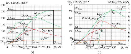
Figure 1.
Annual fuel reduction ΣBe and its relative values ΣBe/Q0 referred to design cooling capacity Q0 over the whole range of ΣBe (a) and values Σ(Be − Be.opt)/Q0 beyond the optimum values of ΣBe.opt and Q0.opt (b) for cooling ambient air to ta2 = 10, 15, and 20 °C.
The rational value of design cooling capacity Q0.rat that provides a close to maximum annual fuel saving ΣBe is associated with the second maximum rate of the annual fuel saving increment ΣBe/Q0 within its range beyond the first maximum rate: Q0 > Q0.opt and ΣBe > ΣBe.opt, respectively. With this, a relative parameter Σ(Be − Be.opt)/Q0 is used as indicator to determine a rational value Q0.rat (Figure 1b).
The optimum Q0.opt and rational Q0.rat values of the cooling capacities for ta2 = 10, 15, and 20 °C were calculated for temperate climatic conditions of Voznesensk, Mykolayiv region (southern Ukraine), 2017 year (Figure 1).
A maximum rate of annual fuel reduction ΣBe increment ΣBe/Q0 for ta2 = 10 °C takes place at the optimum design cooling capacity Q0.opt of about 900 kW (Figure 1a). A maximum rate of annual fuel reduction increment Σ(Be − Be.opt)/Q0 within the range beyond the value ΣBe.opt = 190 t corresponding to Q0.opt = 900 kW takes place at the rational design cooling capacity Q0.rat = 1450 kW and provides annual fuel reduction ΣBe.rat = 250 t that is very close to its maximum value 260 t but at a reduced design cooling capacity Q0.rat = 1450 kW less than Q0.max = 1700 kW by 15%.
The rational distribution of a design cooling capacity in response to the current thermal loads, as the second step of the methodology, requires comparing the available cooling capacity of the chillers with current cooling loads to determine the excessive available cooling capacity to cover the peaked current thermal loads.
Because of the great uncertainty of magnitude of the unstable boost (“turbulent”) load range, its design value q0.b should be determined by a remaining principle as the difference between the overall design cooling capacity q0.10rat for cooling the ambient air to the target temperature ta2 = 10 °C and its basic stable (“laminar”) load range q0.10-15 for subcooling the air from a threshold air temperature of about 15 °C after ACh to ta2 = 10 °C: q0.b10-15rat = q0.10rat − q0.10-15, where q0.10-15 = q0.10 − q0.15.
The flow chart of the calculation procedure is presented in Appendix A.
3. Results
The further development of the methodology of the TIAC system designing consists of the distribution of the overall design cooling capacity between the unstable (“turbulent”) thermal load range for ambient air precooling as a boost range covered by ACh and a stable (“laminarized”) load range as a basic one for further air subcooling to the target temperature by ECh (Figure 2).
Figure 2.
Current values of specific cooling capacities q0.15 needed for cooling ambient air to ta2 = 15 °C; rational design cooling capacities q0.10rat, q0.15rat, and q0.20rat for ta2 = 10, 15, and 20 °C, respectively; current cooling capacities q0.10-15 for cooling air from ta2 = 15 to 10 °C and current residual boost part q0.b10-15 available for cooling air ta2 = 15 °C (a) and boost part q0.b10-20 available for cooling air to ta2 = 20 °C (b).
The values of the current specific cooling capacities q0.15 required for cooling ambient air to 15 °C; rational design cooling capacities q0.10rat, q0.15rat, and q0.20rat for cooling ambient air to 10, 15, and 20 °C, respectively; the basic current cooling capacity q0.10-15 required for cooling air from 15 °C to 10 °C; and the available current residual boost cooling capacities q0.b10-15 and q0.b10-20 are calculated for climatic conditions in Voznesensk, Mykolayiv region (southern Ukraine) in July 2017 (Figure 2).
The current values of capacities for subcooling air q0.10-15 and q0.10-20 are calculated as q0.10-15 = q0.10 − q0.15 and q0.10-20 = q0.10 − q0.20, where q0.10, q0.15, and q0.20 are determined according to Equation (2) for ta2 = 10, 15, and 20 °C.
The values of available residual boost part of rational design cooling capacity are calculated as q0.b10-15 = q0.10rat − q0.10-15 and q0.b10-20 = q0.10rat − q0.10-20 for cooling air to ta2 = 15 and 20 °C, respectively.
The rational design values of cooling capacities q0.10rat, q0.15rat, and q0.20rat for cooling air to 10, 15, and 20 °C are determined by developed method (Figure 1).
As Figure 2 shows, with cooling ambient air to 15 °C the fluctuations of the current thermal loads q0.15 are gradual, that points to inevitable considerable excess of design cooling capacity in the temperate daily hours. At the same time, when air is subcooled from 15 °C to 10 °C, the fluctuations in the thermal load q0.10-15 are comparably small. Thus, the temperature of cooled air ta2 = 15 °C can be reasonably assumed as the threshold value for shearing the overall design’s thermal load on the TIAC system q0.10rat into a comparably stable (“laminarized”) load range q0.10-15 and the boost unstable (“turbulent”) range of ambient air precooling. So, the stable load value q0.10-15 is chosen as a basic stable part q0.10-15 of the design cooling capacity q0.10rat = 35 kJ/kg (Figure 2a). Accordingly, the remaining part of q0.10rat is used for precooling the ambient air to the threshold temperature ta2 = 15 °C and determined as the boost cooling capacity q0.b10-15rat (Figure 2b). The unstable q0.15 thermal load range can be covered by the ACh, as well as the stable q0.10-15 thermal load range by ECh (Figure 3).
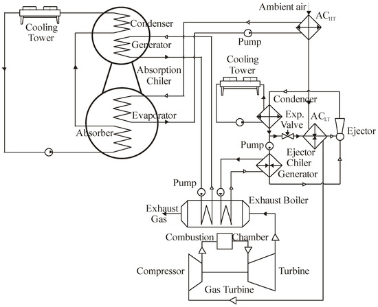
Figure 3.
A circuit of hybrid two-stage TIAC system in AECh with ACh as high temperature and ECh as low temperature stages: ACHT and ACLT—high and low temperature stages of air cooler; Exp. Valve—expansion valve.
According to the proposed circuit of the hybrid two-stage TIAC system, the ACh provides ambient air cooling to 15 °C in a high-temperature air cooler ACHT by chilled water with temperature of about 7 °C, and ECh provides further cooling air to 10 °C and lower in a low-temperature air cooler ACLT by refrigerant boiling at the temperatures of about 5 °C to 2 °C. The thermal load of the ECh is stabilized due to ambient air cooling to threshold temperature of about 15 °C. A steam generated in the exhaust gas boiler is used for feeding to generators of ACh and ECh. The heat of the condensation is extracted from the ACh and ECh condensers through cooling towers.
As Figure 2a shows, the available boost cooling capacity q0.b10-15rat generally covers current thermal loads q0.15 for precooling the ambient air to ta2 = 15 °C. Furthermore, even less available boost cooling capacity q0.b10-20rat also covers the current loads q0.15 except for quite short periods of daylight hours (Figure 2b).
It is quite evident that the further reserves to enhance the efficiency of TIAC systems are within the unstable boost load range of q0.b10-15rat for precooling ambient air to the temperature of 15 °C in ACh and can be realized by utilizing the excessive cooling capacity accumulated at a lowered thermal load on ACh to cover picked loads, which enables reducing the design cooling capacity of ACh.
Therefore, the next step in further enhancing the efficiency of the TIAC systems and development of their design methodology is issued from the behavior of daily available boost the thermal load q0.b10-20 and the current thermal load q0.15 fluctuations (Figure 4).
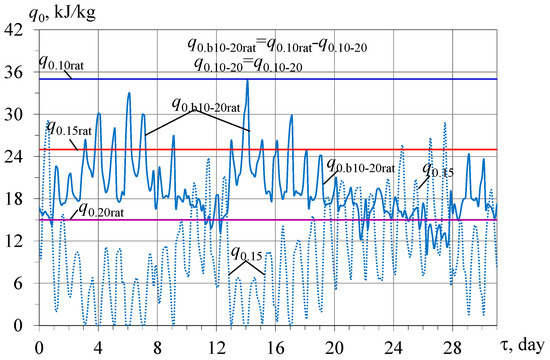
Figure 4.
Current values of specific thermal load q0.15 for cooling ambient air to ta2 = 15 °C, available design specific boost cooling capacity q0.b10-20rat for cooling ambient air to ta2 = 20 °C: q0.b10-20rat = q0.10rat − q0.10-20, q0.10-20 = q0.10 − q0.20.
As Figure 4 shows, the available boost cooling capacities q0.b10-20rat for cooling ambient air to ta2 = 20 °C generally cover the current thermal loads q0.15 for precooling ambient air to ta2 = 15 °C. It is approved by comparing the excesses of available design boost cooling capacities q0.b10-20rat − q0.15 over required q0.15 for ta2 = 15 °C and deficit of design boost cooling capacity q0.15 − q0.b10-20rat (Figure 5).
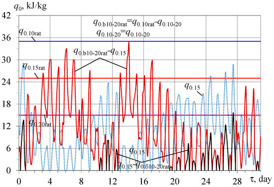
Figure 5.
Current values of specific thermal load q0.15 for cooling ambient air to ta2 = 15 °C, excesses of available rational design boost cooling capacities q0.b10-20rat − q0.15 over required q0.15 for ta2 = 15 °C, deficit of design boost cooling capacity q0.15 − q0.b10-20rat: q0.10-20 = q0.10 − q0.20, q0.b10-20rat = q0.10rat − q0.10-20.
Because of the large fluctuations in the available design boost cooling capacity q0.b10-20rat for cooling ambient air to 20 °C, the corresponding excess available boost cooling capacity q0.b10-20rat − q0.15 over required q0.15 for cooling air 15 °C, and the deficit of the boost cooling capacity q0.15 − q0.b10-20rat, it is problematic to estimate the daily accumulated excess of the design cooling capacity over its required value q0.15 for cooling air to 15 °C during the month (Figure 5).
Proceeding from this, a new approach to share the thermal loads within the unstable boost range q0.b10-15rat in two parts, q0.b10-20rat and q0.15-20, and analyze daily accumulated excess q0.b10-20rat − q0.15 of available boost cooling capacity q0.20rat over cooling needs q0.15 for cooling air to 15 °C is proposed. The accumulated excess of available boost cooling capacity q0.b10-20rat − q0.15 can be used to cover daily deficit q0.15 − q0.b10-20rat at peaked loads. On comparing current values of excess q0.b10-20rat − q0.15 and deficit q0.15 − q0.b10-20rat as resulting refrigeration energy accumulated Σ(q0.b10-20rat − q0.15)τ, the hypothesis to use a reduced value q0.20rat designed for cooling air to 15 °C to cover the current cooling needs q0.15 has been approved (Figure 5 and Figure 6). This results in reduction of design boost thermal load range of q0.b10-15rat and q0.15rat, accordingly.
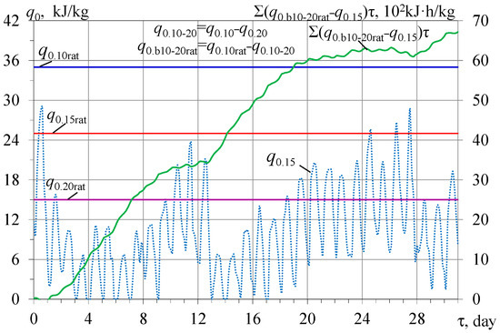
Figure 6.
Current values of specific thermal load q0.15 for cooling ambient air to ta2 = 15 °C and summarized excesses of available accumulated boost refrigeration energy Σ(q0.b10-20rat − q0.15)τ over required cooling capacities q0.15:q0.b10-20rat = q0.10rat − q0.10-20; q0.10-20 = q0.10 − q0.20.
There following correlations are applied:
Current excesses of available rational design boost cooling capacity q0.b10-20rat − q0.15;
Current deficit of design boost cooling capacity q0.15 − q0.b10-20rat;
Summarized excess of available accumulated boost refrigeration energy Σ(q0.b10-20rat − q0.15)τ.
As Figure 5 testifies, the available boost cooling capacity q0.b10-20rat designed for precooling ambient air to ta2 = 20 °C is generally enough to cover the current cooling needs q0.15 for cooling air to ta2 = 15 °C. The current deficit of design boost cooling capacity q0.15 − q0.b10-20rat can be covered by using the daily accumulated excessive refrigeration energy.
This statement is approved by the continuously arising curve of the summarized excess of available accumulated boost refrigeration energy over its current needs Σ(q0.b10-20rat − q0.15)τ (Figure 6).
A practically continuously arising character of the curve of the summarized excesses of the available boost refrigeration energy over its current needs Σ(q0.b10-20rat − q0.15)τ indicates the addition reserve to reduce a design boost cooling capacity for instance through using the optimum design boost cooling capacity q0.b10-20opt instead of its rational value q0.b10-20rat (Figure 7).
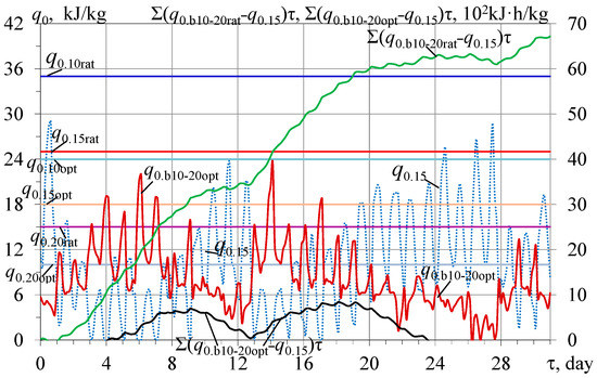
Figure 7.
Current specific thermal loads q0.15 for cooling ambient air to ta2 = 15 °C, available optimum boost cooling capacities q0.b10-20opt for precooling air to ta2 = 20 °C and summarized excess of available accumulated refrigeration energy according to optimum Σ(q0.b10-20opt − q0.15)τ and rational Σ(q0.b10-20rat − q0.15)τ designing: q0.b10-20opt = q0.10opt − q0.10-20; q0.10-20 = q0.10 − q0.20.
As it is seen, the values of the available optimum design boost cooling capacity q0.b10-20opt for ambient air precooling to ta2 = 20 °C are less than the current values of the thermal load q0.15 needed for cooling ambient air to ta2 = 15 °C in the beginning of the month (from 9 to 13 July) and after 18 July. This leads to dropping the curve of the summarized excessive values over the current needs Σ(q0.b10-20opt − q0.15)τ as compared to the curve Σ(q0.b10-20rat − q0.15)τ of the summarized excessive available accumulated refrigeration energy according to rational design (Figure 7). A sharp falling character of the summarized excessive accumulated refrigeration energy curve Σ(q0.b10-20opt − q0.15)τ indicates the lack of daily accumulated refrigeration energy to cover current increased thermal loads q0.15.
The reason for this is a considerable reduced value of optimum design cooling capacity q0.10opt = 24 kJ/kg preliminary accepted as compared with rational value q0.10rat = 35 kJ/kg. Therefore, the next step of analysis focuses the choice of reduced design cooling capacity of TIAC system to minimize the duration of falling part of the summarized excessive available accumulated refrigeration energy curve Σ(q0.b10-20opt − q0.15)τ.
4. Discussion
From the above-presented results, it is quite reasonable to reduce a design cooling capacity q0.10rat. Therefore, a middle value q0.10m = (q0.10rat + q0.10opt)/2 is accepted as the first approximation (Figure 8).
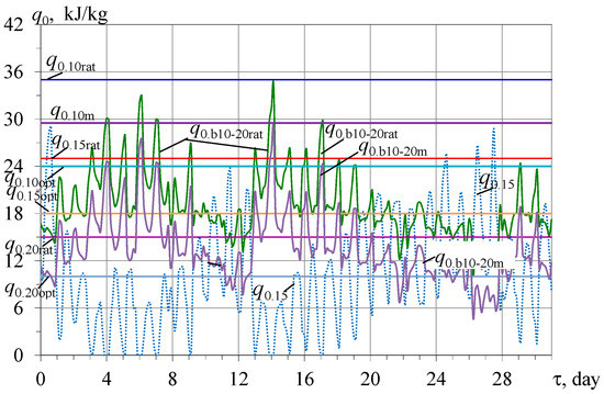
Figure 8.
Current available specific boost cooling capacities q0.b10-20rat and q0.b10-20m for cooling ambient air to ta2 = 20 °C: q0.b10-20rat = q0.10rat − q0.10-20; q0.b10-20m = q0.10m − q0.10-20; q0.10m = (q0.10rat + q0.10opt)/2; q0.10-20 = q0.10 − q0.20.
As Figure 8 shows, the current values of the excess of the available boost cooling capacity q0.b10-20m, based on the middle value q0.10m = (q0.10rat + q0.10opt)/2, in the most days in July are higher than the current thermal loads q0.15. However, from 11 to 13 and 21 to 28 July, the values q0.b10-20m are lower than q0.15 and corresponding current excess of the available boost cooling capacity q0.b10-20m − q0.15 is less than the value of its deficit q0.15 − q0.b10-20m (Figure 9). Due to increased middle boost cooling capacity q0.10m as compared with its optimum value q0.10opt, a drop in the curve of the summarized excess of the available accumulated refrigeration energy Σ(q0.b10-20m − q0.15)τ for the middle value q0.10m is not so sharp as compared with the value of Σ(q0.b10-20opt − q0.15)τ for the rational value q0.10rat (Figure 9).
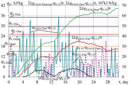
Figure 9.
Current values of excess of available middle design cooling capacity q0.b10-20m − q0.15, deficit of middle design cooling capacity q0.15 − q0.b10-20m, and summarized excess of available accumulated refrigeration energy according to optimum Σ(q0.b10-20opt − q0.15)τ and rational Σ(q0.b10-20rat − q0.15)τ designing and middle values Σ(q0.b10-20m − q0.15)τ.
The analysis of the summarized values of the excessive available accumulated refrigeration energy Σ(q0.b10-20 − q0.15)τ for different design cooling capacities q0.10 makes it possible to determine their reasonably reduced design value to minimize the lack of daily accumulated refrigeration energy to cover current increased thermal loads q0.15 (Figure 10).
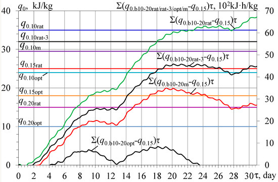
Figure 10.
Summarized values of the excessive available accumulated refrigeration energy over needed values for cooling ambient air to ta2 = 15 °C based on the rational Σ(q0.b10-20rat − q0.15)τ, optimum Σ(q0.b10-20opt − q0.15)τ, their middle Σ(q0.b10-20m − q0.15)τ values, and the rational value Σ(q0.b10-20rat-3 − q0.15)τ decreased by 3 kJ/kg: q0.b10-20rat = q0.10rat − q0.10-20; q0.b10-20opt = q0.10opt − q0.10-20; q0.b10-20m = q0.10m − q0.10-20; q0.b10-20rat-3 = q0.10rat-3 − q0.10-20; q0.10m = (q0.10rat + q0.10opt)/2; q0.10rat-3 = q0.10rat − 3 kJ/kg; q0.10-20 = q0.10 − q0.20.
As Figure 10 shows, changing the design cooling capacities from q0.10rat to q0.10opt, the middle q0.10m and rational value decreased by 3 kJ/kg as q0.10rat-3 enables the regulation of the character of the curves of the summarized available accumulated refrigeration energy excesses Σ(q0.b10-20rat − q0.15)τ, Σ(q0.b10-20opt − q0.15)τ, and Σ(q0.b10-20m − q0.15)τ and decreased the rational value Σ(q0.b10-20rat-3 − q0.15)τ accordingly.
The proposed method of the thermal load analysis based on the character of the summarized excessive available accumulated makes it possible to reduce a design cooling capacity due to its rational distribution and simultaneously to cover the peaked current thermal loads by the excessive refrigeration energy accumulated daily.
The calculation results of reducing the installed cooling capacities of the chillers due to their rational distribution in response to actual current thermal loads according to proposed designing methodology are presented in Figure 11. As it was mentioned, the annual fuel reduction ΣBe is assumed as a primary criterion.
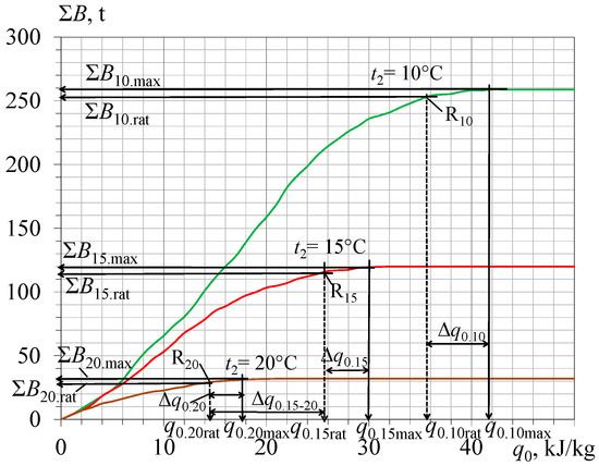
Figure 11.
Annual fuel reduction ΣBe versus specific design cooling capacity q0 for cooling ambient air to ta2 = 10, 15, and 20 °C: ΣB10;15;20—for ta2 = 10, 15, 20 °C; Δq0.10,15,20 = q0.10,15,20max − q0.10,15,20rat; points R10,15,20—rational values of q0.10,15,20rat and ΣB10,15,20rat.
The following correlations are used:
Reduction of the design cooling capacity of AECh Δq0.10 = q0.10max − q0.10rat and of ACh Δq0.15 = q0.15max − q0.15rat for cooling to ta2 = 15 °C and Δq0.20 = q0.20max − q0.20rat for ta2 = 15 °C due to the rational design cooling capacities compared with traditional maximum values;
Reduction of design cooling capacity of ACh boost stage Δq0.15-20 = q0.15rat − q0.20rat due to its rational distribution.
As Figure 11 shows, the rational designing of the TIAC systems provides a reduction of the installed cooling capacities of the chillers by the values of Δq0.10,15,20, i.e., by 15 to 20% compared with their maximum magnitudes q0.10,15,20max, calculated issuing from the conventional practice of designing. In addition, the rational distribution of the installed cooling capacity of ACh makes it possible to reduce a design boost thermal load by the value Δq0.15-20 = q0.15rat − q0.20rat, i.e., practically twice as high compared with the initial value q0.15rat.
As well as the proposed absorption–ejector TIAC systems are the advanced versions of typical basic absorption TIAC system, the economic comparison might be conducted taking into account only the cost of extra heat exchangers of ECh (refrigerant evaporator-air cooler, refrigerant condenser, and ejector) with unchanged maintenance cost, personal costs, etc.
As a basic version, a TIAC system for the gas turbine of the power output of 10 MW and air mass flow rate Ga = 40 kg/s is accepted for easy application of the calculation results for turbines with other characteristics. According to Figure 11, the rational specific cooling capacities q0.10rat = 35 kW/(kg/s) for the TIAC system with AECh and q0.15rat = 24 kW/(kg/s) for conventional ACh or their total values Q0.10rat = 1400 kW and Q0.15rat = 960 kW are assumed. The annual specific fuel reduction Σb10rat = 47 kg/kW and Σb15rat = 26 kg/kW or corresponding gas turbine annual total fuel reduction ΣB10rat = 470 t and ΣB15rat = 260 t are gained due to the intake of air cooling to 10 °C and 15 °C, accordingly. With this, a deeper air subcooling from 15 °C to 10 °C in ECh of the total cooling capacity Q0.10-15rat = Q0.10rat − Q0.15rat, i.e., 440 kW, provides additional annual fuel reduction ΣB10-15rat = ΣB10rat − ΣB15rat about 210 t as compared with conventional TIAC system with ACh.
Thus, the following additional heat exchanges of ECh are needed: refrigerant evaporator-air cooler with cooling capacity of Q0.10-15rat = 440 kW and refrigerant condenser with thermal load of Qcondenser = Q0.10-15rat (1 + COP), i.e., about 1760 kW, where COP of ECh can be accepted as 0.3. Taking into account the cost of additional heat exchangers of about USD 150,000 according to [63], increased by 10% for the mounting of ejector and heat exchangers, the cost of the additional equipment is about USD 180,000. At the same time, the cost of gas fuel annually saved is about USD 300,000. Proceeding from the price of gas of USD 1000 per 1000 m3, the payback period is about a year.
Because of the fluctuations in the price of gas fuel and the cost of heat exchangers from various manufacturers the economic analysis has to be conducted for a quite definite case. The considered method of designing focuses to provide the rational technical characteristics as initial basic data for further complicated detailed economic analysis.
5. Conclusions
A novel trend in TIAC by two-stage air cooling in combined AECh with ACh as a high-temperature stage for ambient air cooling to cover the range of fluctuated thermal load and ECh as a low-temperature stage for further air subcooling at practically stable thermal load is proposed to provide about 50% higher annual fuel saving in temperate climatic conditions.
The reserve of further enhancing the efficiency of the TIAC system by the rational distribution of design cooling capacity within the range of fluctuated thermal load is revealed. It can be realized by using the excess of ACh design cooling capacity accumulated at lowered current thermal loads to cover the peaked loads that enables an almost twofold reduction in the installed cooling capacity of ACh.
An advanced methodology is developed to determine a rational design cooling capacity of TIAC systems that provide close to the maximum annual fuel savings at decreased installed cooling capacity by 15 to 20% as compared with conventional TIAC designing practice.
Issuing from the daily fluctuations of the excess and deficits of cooling capacities, a new methodological approach is proposed to define a design cooling capacity of ACh reduced practically twofold due to its rational distribution through accumulating excessive refrigeration energy at lowered current thermal loads to cover their picked values by boost air precooling.
Author Contributions
Conceptualization, M.R., A.R. and R.R.; methodology, Z.Y., M.R., A.R., D.M. and R.R.; software, M.R., A.R. and R.R.; validation, M.R., A.R. and R.R.; formal analysis, Z.Y., M.R., A.R., D.M. and R.R.; investigation, Z.Y., M.R., A.R., D.M. and R.R.; resources, A.R. and R.R.; data curation, M.R., A.R. and R.R.; writing—original draft preparation, M.R., A.R. and R.R.; writing—review and editing, Z.Y., M.R., A.R., D.M. and R.R.; visualization, M.R., A.R. and R.R.; supervision, M.R.; project administration, M.R.; funding acquisition, Z.Y. All authors have read and agreed to the published version of the manuscript.
Funding
This research received no external funding.
Institutional Review Board Statement
Not applicable.
Informed Consent Statement
Not applicable.
Data Availability Statement
Not applicable.
Conflicts of Interest
The authors declare no conflict of interest.
Nomenclature
| AC | air cooler | |
| ACHT | high-temperature air cooler | |
| ACLT | low-temperature air cooler | |
| ACh | absorption lithium-bromide chiller | |
| AECh | absorption–ejector chiller | |
| COP | coefficient of performance | |
| ECh | ejector chiller | |
| EIAC | engine intake air cooling | |
| HExch | heat exchangers | |
| O | optimal point for maximum rate of annual fuel reduction increment | |
| R | rational point for closed to maximum annual fuel reduction | |
| TIAC | turbine intake air cooling | |
| Symbols and units | ||
| B | total mass fuel consumption decrease, B = CDH·(Δbe/Δt)·Pe. | g, kg, t |
| be | specific fuel consumption | g/kWh |
| ca | specific heat of humid air | kJ/(kg·K) |
| CDH | CDH = Δt·τ | K·h |
| damb | ambient air absolute humidity | g/kg |
| Ga | air mass flow rate | kg/s |
| Pe | power output | kW |
| Q0 | total cooling capacity, heat flow rate | kW |
| q0 | specific cooling capacity—per unit air mass flow rate | kW/(kg/s) or kJ/kg |
| t | temperature | °C |
| tamb | ambient air temperature | °C |
| ta2 | outlet air temperature | °C |
| t0 | refrigerant boiling temperature | °C |
| ξ | specific heat ratio of the total heat (latent and sensible) rejected from air to its sensible heat | |
| τ | time interval | h |
| φamb | ambient air relative humidity | % |
| Δbe | specific fuel consumption decrease | g/kWh |
| Δt | air temperature decrease | K, °C |
| ∑B10,15,20 | annual total fuel reduction due to cooling engine intake air to 10, 15, 20 °C | t |
| ∑b10,15,20 | annual specific fuel reduction (per 1 kW engine power output) due to cooling engine intake air to 10, 15, 20 °C | g, kg, t |
| Subscripts | ||
| a | air | |
| amb | ambient | |
| b | boost | |
| def | deficit | |
| exc | excess | |
| max | maximum | |
| m | mean | |
| opt | optimum | |
| rat | rational | |
Appendix A
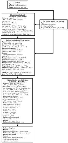
Figure A1.
Flow chart of calculation procedure.
References
- Farouk, N.; Sheng, L.; Hayat, Q. Effect of Ambient Temperature on the Performance of Gas Turbines Power Plant. Int. J. Comput. Sci. 2013, 10, 439–442. [Google Scholar]
- Erdem, H.H.; Sevilgen, S.H. Case study: Effect of ambient temperature on the electricity production and fuel consumption of a simple cycle gas turbine in Turkey. Appl. Therm. Eng. 2006, 26, 320–326. [Google Scholar] [CrossRef]
- Hashmi, M.B.; Lemma, T.A.; Karim, Z.A. Investigation of the Combined Effect of Variable Inlet Guide Vane Drift, Fouling, and Inlet Air Cooling on Gas Turbine Performance. Entropy 2019, 21, 1186. [Google Scholar] [CrossRef] [Green Version]
- De Sa, A.; Al Zubaidy, S. Gas turbine performance at varying ambient temperature. Appl. Therm. Eng. 2011, 31, 2735–2739. [Google Scholar] [CrossRef]
- Dawoud, B.; Zurigat, Y.H.; Bortmany, J. Thermodynamic assessment of power requirements and impact of different gas-turbine inlet air cooling techniques at two different locations in Oman. Appl. Therm. Eng. 2005, 25, 1579–1598. [Google Scholar] [CrossRef]
- Popli, S.; Rodgers, P.; Eveloy, V. Gas turbine efficiency enhancement using waste heat powered absorption chillers in the oil and gas industry. Appl. Therm. Eng. 2013, 50, 918–931. [Google Scholar] [CrossRef]
- Popli, S.; Rodgers, P.; Eveloy, V. Trigeneration scheme for energy efficiency enhancement in a natural gas processing plant through turbine exhaust gas waste heat utilization. Appl. Energy 2012, 93, 623–636. [Google Scholar] [CrossRef]
- Radchenko, A.; Stachel, A.; Forduy, S.; Portnoi, B.; Rizun, O. Analysis of the efficiency of engine inlet air chilling unit with cooling towers. In Lecture Notes in Mechanical Engineering, Advances in Design, Simulation and Manufacturing III, Proceedings of the 3rd International Conference on Design, Simulation, Manufacturing: The Innovation Exchange, DSMIE-2020, Kharkiv, Ukraine, 9–12 June 2020; Ivanov, V., Pavlenko, I., Liaposhchenko, O., Machado, J., Edl, M., Eds.; Springer: Cham, Switzerland, 2020; pp. 322–331. [Google Scholar] [CrossRef]
- Komuro, T.; Ito, E.; Sonoda, T.; Tomita, Y.; Hidaka, K.; Shibutani, S. Power output augmentation of gas turbine combined cycle by inlet-air cooling system of chiller type under high ambient air temperature. Mitsubishi Heavy Ind. Tech. Rev. 2010, 47, 33–39. [Google Scholar]
- Kwon, H.M.; Kim, T.S.; Sohn, J.L. Performance improvement of gas turbine combined cycle power plant by dual cooling of the inlet air and turbine coolant using an absorption chiller. Energy 2018, 163, 1050–1061. [Google Scholar] [CrossRef]
- Al-Tahaineh, H.A. Cooling of compressor air inlet of a gas turbine power plant using ammonia-water vapor absorption system. Int. J. Energy Eng. 2013, 3, 267–271. [Google Scholar]
- Bortmany, J.N. Assesstment of aqua-ammonia refrigeration for pre-cooling gas turbine inlet air. In Proceedings of the ASME TURBO EXPO 2002, Amsterdam, The Netherlands, 3–6 June 2002. Paper GT-2002-30657; 12p. [Google Scholar]
- Wan, X.; Chua, H. Absorption Cooling: A review of Lithium Bromide-Water chiller technologies. Recent Pat. Mech. Eng. 2009, 2, 193–213. [Google Scholar]
- Mahmoudi, S.M.; Zare, V.; Ranjbar, F.; Farshi, L.J. Energy and exergy analysis of simple and regenerative gas turbines inlet air cooling using absorption refrigeration. Appl. Sci. 2009, 9, 2399–2407. [Google Scholar] [CrossRef]
- Ibrahim, T.K.; Rahman, M.M.; Abdalla, A.N. Improvement of gas turbine performance based on inlet air cooling systems: A technical review. Int. J. Phys. Sci. 2011, 6, 620–627. [Google Scholar]
- Ghaebi, H.; Karimkashi, S.; Saidi, M.H. Integration of an absorption chiller in a total CHP site for utilizing its cooling production potential based on R-curve concept. Int. J. Refrig. 2012, 35, 1384–1392. [Google Scholar] [CrossRef]
- Al-Ibrahim, A.M.; Varnham, A. A review of inlet air-cooling technologies for enhancing the performance of combustion turbines in Saudi Arabia. Appl. Therm. Eng. 2010, 30, 1879–1888. [Google Scholar] [CrossRef]
- Elberry, M.F.; Elsayed, A.; Teamah, M.; Abdel-Rahman, A.; Elsafty, A. Performance improvement of power plants using absorption cooling system. Alex. Eng. J. 2018, 57, 2679–2686. [Google Scholar] [CrossRef]
- Barreto, D.; Fajardo, J.; Caballero, G.C.; Escorcia, Y.C. Advanced exergy and exergoeconomic analysis of a gas power system with steam injection and air cooling with a compression refrigeration machine. Energy Technol. 2021, 9, 2000993. [Google Scholar] [CrossRef]
- Trushliakov, E.; Radchenko, A.; Radchenko, M.; Kantor, S.; Zielikov, O. The efficiency of refrigeration capacity regulation in the ambient air conditioning systems. In Lecture Notes in Mechanical Engineering, Advances in Design, Simulation and Manufacturing III, Proceedings of the 3rd International Conference on Design, Simulation, Manufacturing: The Innovation Exchange, DSMIE-2020, Kharkiv, Ukraine, 9–12 June 2020; Ivanov, V., Pavlenko, I., Liaposhchenko, O., Machado, J., Edl, M., Eds.; Springer: Cham, Switzerland, 2020; pp. 343–353. [Google Scholar] [CrossRef]
- Radchenko, A.; Trushliakov, E.; Tkachenko, V.; Portnoi, B.; Prjadko, O. Improvement of the refrigeration capacity utilizing for the ambient air conditioning system. In Lecture Notes in Mechanical Engineering, Advanced Manufacturing Processes II, Selected Proceedings of the 2nd Grabchenko’s International Conference on Advanced Manufacturing Processes (InterPartner-2020), Odessa, Ukraine, 8–11 September 2020; Tonkonogyi, V., Ivanov, V., Trojanowska, J., Oborskyi, G., Grabchenko, A., Pavlenko, I., Edl, M., Kuric, I., Dasic, P., Eds.; Springer: Cham, Switzerland, 2021; pp. 714–723. [Google Scholar]
- Butrymowicz, D.; Gagan, J.; Śmierciew, K.; Łukaszuk, M.; Dudar, A.; Pawluczuk, A.; Łapiński, A.; Kuryłowic, A. Investigations of prototype ejection refrigeration system driven by low grade heat. In Proceedings of the HTRSE-2018, E3S Web of Conferences 2018, Międzyzdroje, Poland, 2–5 September 2018; Volume 70. 7p. [Google Scholar]
- Shukla, A.K.; Sharma, A.; Sharma, M.; Mishra, S. Performance improvement of simple gas turbine cycle with vapor compression inlet air cooling. Mater. Today Proc. 2018, 5, 19172–19180. [Google Scholar] [CrossRef]
- Tiwari, A.K.; Hasan, M.M.; Islam, M. Effect of ambient temperature on the performance of a combined cycle power plant. Trans. Can. Soc. Mech. Eng. 2013, 37, 1177–1188. [Google Scholar] [CrossRef] [Green Version]
- Radchenko, A.; Trushliakov, E.; Kosowski, K.; Mikielewicz, D.; Radchenko, M. Innovative turbine intake air cooling systems and their rational designing. Energies 2020, 13, 6201. [Google Scholar] [CrossRef]
- Radchenko, M.; Radchenko, A.; Radchenko, R.; Kantor, S.; Konovalov, D.; Kornienko, V. Rational loads of turbine inlet air absorption-ejector cooling systems. Proc. Inst. Mech. Eng. Part A J. Power Energy 2021. [Google Scholar] [CrossRef]
- Chacartegui, R.; Jiménez-Espadafor, F.; Sánchez, D.; Sánchez, T. Analysis of combustion turbine inlet air cooling systems applied to an operating cogeneration power plant. Energy Convers. Manag. 2008, 49, 2130–2141. [Google Scholar] [CrossRef]
- Abusaa, G.; Issa, K. Performance Improvements of Power Generation Using Waste Heat Hybrid Cooling Plant. Kingdom TRIGENERATION Summit 29th September, 2013, 24p. Available online: https://www.sciencedirect.com/topics/engineering/power-generation-efficiency (accessed on 22 June 2021).
- Morini, M.; Venturini, M. An innovative inlet air cooling system for igcc power augmentation part I: Analysis of igcc plant components. In Proceedings of the ASME Turbo Expo 2012, Copenhagen, Denmark, 11–15 June 2012. Paper No. 2012-68346. [Google Scholar]
- Morini, M.; Pinelli, M.; Spina, P.R. An innovative inlet air cooling system for igcc power augmentation part II: Thermodynamic analysis. In Proceedings of the ASME Turbo Expo 2012, Copenhagen, Denmark, 11–15 June 2012. Paper No. 2012-68352. [Google Scholar]
- Dizaji, H.S.; Hu, E.J.; Chen, L.; Pourhedayat, S. Using novel integrated Maisotsenko cooler and absorption chiller for cooling of gas turbine inlet air. Energy Convers. Manag. 2019, 195, 1067–1078. [Google Scholar] [CrossRef]
- Zhu, G.; Chow, T.-T.; Lee, C.-K. Performance analysis of biogas-fueled Maisotsenko combustion turbine cycle. Appl. Therm. Eng. 2021, 195, 117247. [Google Scholar] [CrossRef]
- Kornienko, V.; Radchenko, M.; Radchenko, R.; Konovalov, D.; Andreev, A.; Pyrysunko, M. Improving the efficiency of heat recovery circuits of cogeneration plants with combustion of water-fuel emulsions. Therm. Sci. 2021, 25, 791–800. [Google Scholar] [CrossRef] [Green Version]
- Kondratenko, Y.; Korobko, V.; Korobko, O.; Kondratenko, G.; Kozlov, O. Green-IT Approach to Design and Optimization of Thermoacoustic Waste Heat Utilization Plant Based on Soft Computing. Green IT Engineering: Components, Networks and Systems Implementation. Studies in Systems, Decision and Control; Springer: Cham, Switzerland, 2017; Volume 105, pp. 287–311. [Google Scholar] [CrossRef]
- Radchenko, R.; Pyrysunko, M.; Kornienko, V.; Scurtu, I.-C.; Patyk, R. Improving the ecological and energy efficiency of internal combustion engines by ejector chiller using recirculation gas heat. In Lecture Notes in Networks and Systems, Proceedings of the Advances in Intelligent Systems and Computing, International Scientific and Technical Conference on Integrated Computer Technologies in Mechanical Engineering—Synergetic Engineering, ICTM 2020, Kharkiv, Ukraine, 29–30 October 2020; Nechyporuk, M., Pavlikov, V., Kritskiy, D., Eds.; Springer: Cham, Switzerland, 2021; Volume 188, pp. 531–541. [Google Scholar] [CrossRef]
- Kornienko, V.; Radchenko, R.; Bohdal, Ł.; Kukiełka, L.; Legutko, S. Investigation of condensing heating surfaces with reduced corrosion of boilers with water-fuel emulsion combustion. In Lecture Notes in Networks and Systems, Proceedings of the Advances in Intelligent Systems and Computing, International Scientific and Technical Conference on Integrated Computer Technologies in Mechanical Engineering-Synergetic Engineering, ICTM 2020, Kharkiv, Ukraine, 29–30 October 2020; Nechyporuk, M., Pavlikov, V., Kritskiy, D., Eds.; Springer: Cham, Switzerland, 2021; Volume 188, pp. 300–309. [Google Scholar] [CrossRef]
- Konovalov, D.; Kobalava, H.; Radchenko, M.; Sviridov, V.; Scurtu, I.C. Optimal sizing of the evaporation chamber in the low-flow aerothermopressor for a combustion engine. In Lecture Notes in Mechanical Engineering, Advanced Manufacturing Processes II, Selected Papers from the 2nd Grabchenko’s International Conference on Advanced Manufacturing Processes (InterPartner-2020), Odessa, Ukraine, 8–11 September 2020; Tonkonogyi, V., Ivanov, V., Trojanowska, J., Oborskyi, G., Grabchenko, A., Pavlenko, I., Edl, M., Kuric, I., Dasic, P., Eds.; Springer: Cham, Switzerland, 2021; pp. 654–663. [Google Scholar] [CrossRef]
- Konovalov, D.; Kobalava, H.; Radchenko, M.; Scurtu, I.C.; Radchenko, R. Determination of hydraulic resistance of the aerothermopressor for gas turbine cyclic air cooling. In Proceedings of the E3S Web. Conference, 9th International Conference on Thermal Equipments, Renewable Energy and Rural Development (TE-RE-RD 2020), Constanta, Romania, 26–27 June 2020; EDP Sciences. Volume 180, p. 01012. [Google Scholar] [CrossRef]
- Shukla, A.K.; Singh, O. Impact of Inlet Fogging on the Performance of Steam Injected Cooled Gas Turbine Based Combined Cycle Power Plant; Paper No: GTINDIA2017-4557; V001T03A004; American Society of Mechanical Engineers: New York, NY, USA, 2017; 10p. [Google Scholar] [CrossRef]
- Radchenko, M.; Kobalava, H.; Radchenko, A.; Radchenko, R.; Kornienko, V.; Maksymov, V. Research of characteristics of the flow part of an aerothermopressor for gas turbine intercooling air. Proc. Inst. Mech. Eng. Part A J. Power Energy 2021. [Google Scholar] [CrossRef]
- Wang, K.; Zhao, C.; Cai, Y. Effect of intake air humidification and EGR on combustion and emission characteristics of marine diesel engine at advanced injection timing. J. Therm. Sci. 2021, 30, 1174–1186. [Google Scholar] [CrossRef]
- Zhang, T.; Liu, Z.; Hao, H.; Chang, L.J. Application research of intake-air cooling technologies in gas-steam combined cycle power plants in China. Power Energy Eng. 2014, 2, 304–311. Available online: https://www.scirp.org/journal/paperinformation.aspx?paperid=44921 (accessed on 5 December 2021). [CrossRef]
- Jamaluddin, K.; Wan Alwi, S.R.; Abdul Manan, Z.; Hamzah, K.; Klemeš, J.J. Development of numerical trigeneration system cascade analysis with transmission and storage energy losses consideration. IOP Conf. Ser. Mater. Sci. Eng. 2020, 884, 012019. [Google Scholar] [CrossRef]
- Fumo, N.; Mago, P.J.; Smith, A.D. Analysis of combined cooling, heating, and power systems operating following the electric load and following the thermal load strategies with no electricity export. Proc. Inst. Mech. Eng. Part A J. Power Energy 2011, 225, 1016–1025. [Google Scholar] [CrossRef]
- Yang, C.; Yang, Z.; Cai, R. Analytical method for evaluation of gas turbine inlet air cooling in combined cycle power plant. Appl. Energy 2009, 86, 848–856. [Google Scholar] [CrossRef]
- Chen, Y.; Zhao, D.; Xu, J.; Xu, J.; Wang, J.; Lund, P.D. Performance analysis and exergo-economic optimization of a solar-driven adjustable trigeneration system. Energy Convers. Manag. 2021, 233, 113873. [Google Scholar] [CrossRef]
- Şen, G.; Nil, M.; Mamur, H.; Doğan, H.; Karamolla, M.; Karaçor, M.; Kuyucuoğlu, F.; Yörükeren, N.; Bhuiyan, M.R.A. The effect of ambient temperature on electric power generation in natural gas combined cycle power plant-A case study. Energy Rep. 2018, 4, 682–690. [Google Scholar] [CrossRef]
- Radchenko, M.; Mikielewicz, D.; Tkachenko, V.; Klugmann, M.; Andreev, A. Enhancement of the operation efficiency of the transport air conditioning system. In Lecture Notes in Mechanical Engineering, Advances in Design, Simulation and Manufacturing III, Proceedings of the 3rd International Conference on Design, Simulation, Manufacturing: The Innovation Exchange, DSMIE-2020, Kharkiv, Ukraine, 9–12 June 2020; Ivanov, V., Pavlenko, I., Liaposhchenko, O., Machado, J., Edl, M., Eds.; Springer: Cham, Switzerland, 2020; pp. 332–342. Available online: https://www.springerprofessional.de/en/enhancement-of-the-operation-efficiency-of-the-transport-air-con/18051244 (accessed on 5 December 2021).
- Radchenko, M.; Radchenko, R.; Tkachenko, V.; Kantor, S.; Smolyanoy, E. Increasing the operation efficiency of railway air conditioning system on the base of its simulation along the route line. In Advances in Intelligent Systems and Computing, Proceedings of the International Scientific and Technical Conference on Integrated Computer Technologies in Mechanical Engineering—Synergetic Engineering, ICTM 2019, Kharkiv, 28–30 November 2019; Nechyporuk, M., Pavlikov, V., Kritskiy, D., Eds.; Springer: Cham, Switzerland, 2020; Volume 1113, pp. 461–467. [Google Scholar] [CrossRef]
- Rodriguez-Aumente, P.A.; Rodriguez-Hidalgo, M.C.; Nogueira, J.I.; Lecuona, A.; Venegas, M.C. District heating and cooling for business buildings in Madrid. Appl. Therm. Eng. 2013, 50, 1496–1503. [Google Scholar] [CrossRef]
- Ortiga, J.; Bruno, J.C.; Coronas, A. Operational optimization of a complex trigeneration system connected to a district heating and cooling network. Appl. Therm. Eng. 2013, 50, 1536–1542. [Google Scholar] [CrossRef]
- Cardona, E.; Piacentino, A. A methodology for sizing a trigeneration plant in mediterranean areas. Appl. Therm. Eng. 2003, 23, 15. [Google Scholar] [CrossRef]
- Canova, A.; Cavallero, C.; Freschi, F.; Giaccone, L.; Repetto, M.; Tartaglia, M. Optimal energy management. IEEE Ind. Appl. Mag. 2009, 15, 62–65. [Google Scholar] [CrossRef]
- Chaker, M.; Meher-Homji, C.B.; Mee, T.; Nicolson, A. Inlet fogging of gas turbine engines-detailed climatic analysis of gas turbine evaporative cooling potential. In Proceedings of the ASME International Gas Turbine and Aeroengine Conference, New Orleans, LA, USA, 4–7 June 2001. ASME Paper 2001-GT-526. [Google Scholar]
- Oktay, Z.; Coskun, C.; Dincer, I. A new approach for predicting cooling degree-hours and energy requirements in buildings. Energy 2011, 36, 4855–4863. [Google Scholar] [CrossRef]
- Coskun, C.; Demiral, D.; Ertürk, M.; Oktay, Z. Modified Degree-Hour Calculation Method. Solar Power 2012, Prof. Radu Rugescu (Ed.), InTech. Available online: http://www.intechopen.com/books/solar-power/modified-degree-hour-calculation-method (accessed on 22 June 2021).
- Coskun, C. A novel approach to degree-hour calculation: Indoor and outdoor reference temperature based degree-hour calculation. Energy 2010, 35, 2455–2460. [Google Scholar] [CrossRef]
- Forsyth, J.L. Gas turbine inlet air chilling for LNG. In Proceedings of the IGT International Liquefied Natural Gas Conference, Oran, Algeria, 18–21 April 2010; Volume 3, pp. 1763–1778. [Google Scholar]
- Kalhori, S.B.; Rabiei, H.; Mansoori, Z. Mashad trigeneration potential—An opportunity for CO2 abatement in Iran. Energy Convers. Manag. 2012, 60, 106–114. [Google Scholar] [CrossRef]
- Khaliq, A.; Dincer, I.; Sharma, P.B. Development and analysis of industrial waste heat based trigeneration for combined production of power heat and cold. J. Energy Inst. 2010, 83, 79–85. [Google Scholar] [CrossRef]
- Radchenko, M.; Radchenko, A.; Mikielewicz, D.; Kosowski, K.; Kantor, S.; Kalinichenko, I. Gas turbine intake air hybrid cooling systems and their rational designing. In Proceedings of the V International Scientific and Technical Conference Modern Power Systems and Units (MPSU 2021), E3S Web of Conferences, Krakow, Poland, 19–21 May 2021; Volume 323, p. 00030. [Google Scholar] [CrossRef]
- Valentini, A. Gas Turbine Electrical Stations. Nikolaev, “Zorya-Mashproject”; Zorya-Mashproekt: Nikolaev, Ukraine, 2007; 16p. [Google Scholar]
- Guentner. Available online: https://www.guentner.eu/know-how/product-calculator-gpc/gpc-software/ (accessed on 22 June 2019).
Publisher’s Note: MDPI stays neutral with regard to jurisdictional claims in published maps and institutional affiliations. |
© 2022 by the authors. Licensee MDPI, Basel, Switzerland. This article is an open access article distributed under the terms and conditions of the Creative Commons Attribution (CC BY) license (https://creativecommons.org/licenses/by/4.0/).