Article

The Application of Open Capillary Modules for Sweeping Gas Membrane Distillation

Faculty of Chemical Technology and Engineering, West Pomeranian University of Technology in Szczecin, ul. Pułaskiego 10, 70-322 Szczecin, Poland
Energies 2022, 15(4), 1454; https://doi.org/10.3390/en15041454
Submission received: 14 January 2022 / Revised: 8 February 2022 / Accepted: 15 February 2022 / Published: 16 February 2022
(This article belongs to the Special Issue Thermal Performance of Membrane Distillation)

Abstract

:
The paper presents the sweeping gas membrane distillation realised by using the capillary module (length 1.1 m and area 0.1 m2) without housing (module shell). During the tests, the feed was flowing inside the hydrophobic polypropylene membranes. The studies were performed for two variants of process: with pre-heating (313–330 K) and without heating of the feed (brines). Under low gas flow (0.005 m/s) the evaporation performance varied in the range of 0.15–0.25 L/m2h, depending on the relative humidity (42–63%) and the air temperature (293–300 K). The application of feed pre-heating to 330 K led to an increase in the evaporation performance to 2.4 L/m2h. The permeate flux increased by 60% when the air flow velocities between the capillaries increased to 1.8–2.5 m/s. Increasing the feed flow rate from 0.1 to 0.59 m/s led to increase the permeate flux about 20% for feed temperature 293–310 K, and over 55% for feed temperature higher than 323 K.

1. Introduction

Membrane distillation (MD) is performed by phase change; therefore, this process is energy-consuming and over 2500 kJ/kg of permeate obtained is required [1]. The water released from the feed in the form of vapour flows to the other side of the membrane where it is condensed, e.g., in the cold distillate stream. Such a case is called direct contact MD (DCMD) [2,3]. In the MD process, porous membranes made of hydrophobic polymers with a low thermal conductivity coefficient are used [4,5,6]. However, due to the small thickness of the membranes (e.g., 100 µm), it does not eliminate the heat conduction from the feed to the permeate side and, as a result, heat losses in the DCMD process may exceed 50% [2,7]. This inconvenience was limited by separating the membrane from the cold distillate with a gas layer (Air Gap MD) [8]. In another variant of the MD process, a gas stream flows on the permeate side [1,5]. A flowing gas is used to sweep the vapour out of the membrane permeate side, and this variant is called sweeping gas MD (SGMD) [1,3,4,5,6]. The gaseous layer increases the resistance to heat transfer which decreases the heat loss by conduction. For this reason, the application of the SGMD variant allowed to reduce heat losses to the level of 20% [9]. However, it must be recognised that in order to obtain freshwater from salt water in the SGMD variant, an external vapour condenser should be additionally used [1,10].
Water can also be desalinated by evaporating it from a wet surface of hydrophilic membranes. However, such evaporation caused a rapid crystallization of salts on the membrane surface [11], hence, the hydrophilic membranes can be only used for the separation of feed without solutes. When the hydrophobic membranes are applied, as in the SGMD process, the evaporation of water proceeds at the feed/membrane interface and a cross-flow of non-saturated feed prevents the precipitation of solutes, even for a high concentrated brine [12].
The driving force for mass transport in the MD process is the difference in vapour pressure [2,9]. In the case of SGMD, it results from the vapour pressure at the evaporation surface in the pores of the membrane and the water vapour content in the gas [1,5]. Mass and heat transfer causes both the concentration and temperature in the membrane adjacent layers to differ from those in the bulk (polarization effects), which reduces the driving force [2,5,9]. It has been reported that increasing the turbulence flow of the stream usually allows to limit the influence of polarization phenomena [10,13,14]. The polarization is particularly high on the side of the gas, which quickly becomes saturated with water vapour [
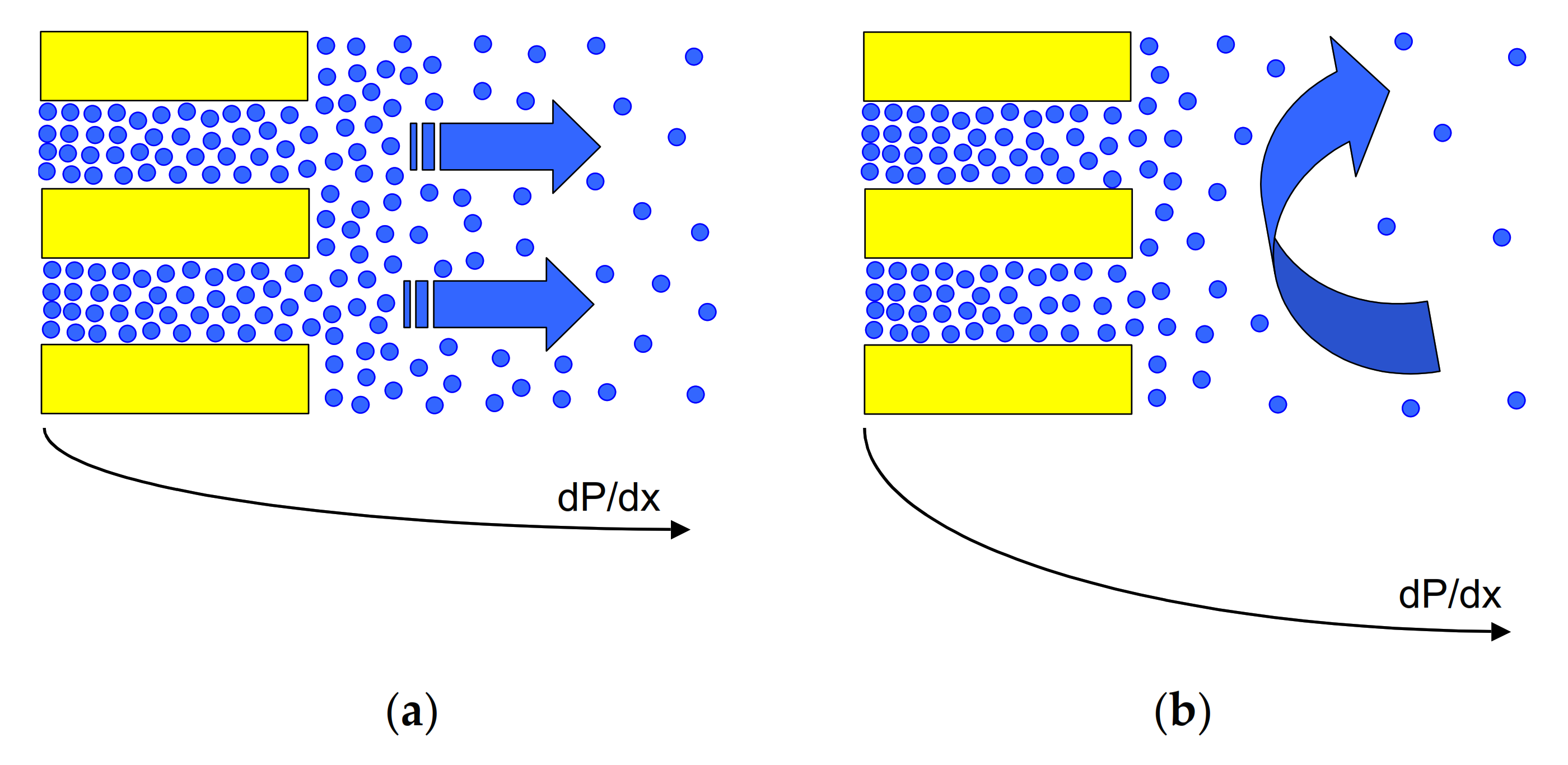
15]. However, in classic modules with high membrane packing density, increasing the gas flow velocity is limited due to a significant increase in flow resistance [4]. To solve this problem, in the present work, an idea of open capillary modules was applied. In the modules, the water evaporation takes place from the surface of capillary membranes, whose bundles are loosely distributed inside large chambers. In such a system, the use of even high gas flow velocities do not cause a significant pressure drop. Apart from the flow velocity, the efficiency of the SGMD process is also influenced by the temperature of the feed and gas [1,
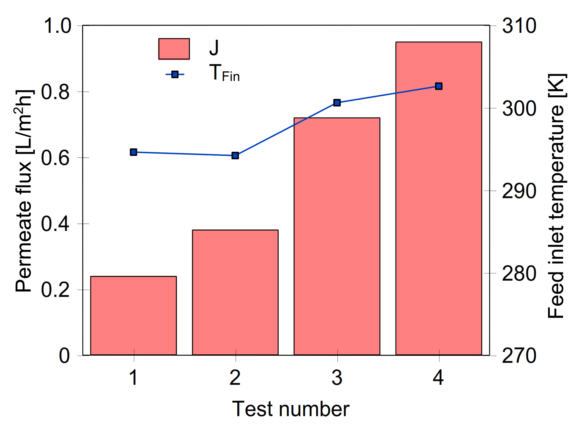
4]. Increasing the feed temperature causes an exponential increase in the saturated vapour pressure, which leads to a significant increase in the driving force of mass transport [15,16]. As a result, the efficiency of the MD process increases, regardless of its variant [17,18,19].
It must be stressed that, in the published articles, the presented assessment of the influence of the process parameters on the SGMD course differs many times. Indeed, increasing the feed flow velocity most often significantly increased the permeate flux [10,15,17,20]; however, in other studies, a slight influence of this parameter was shown [14,18]. The gas temperature at the inlet to the module usually has little effect on the process performance [4,15,21], although its importance was shown in [4]. The discrepancies in the presented results are generally due to the design of the membrane modules used and their size. For example, when the membranes surface is small, the evaporation of water does not cause a significant change in the temperature of the gas transported in large amounts, hence, the influence of the gas temperature on the SGMD efficiency can be observed [21,22]. In the case of using modules with a large membrane surface (e.g., 1–2 m2), due to the mass and heat transport, the gas temperature quickly becomes close to the temperature of the feed and, as a result, this temperature affects the efficiency of the SGMD process [4,22].
The use of small SGMD modules for testing allows for very favourable yields, often above 20 L/m2h [15,16,18,20]. Unfortunately, similarly to large DCMD modules, increasing the process scale causes a multiple decrease in the permeate flux [4,5,6,13,
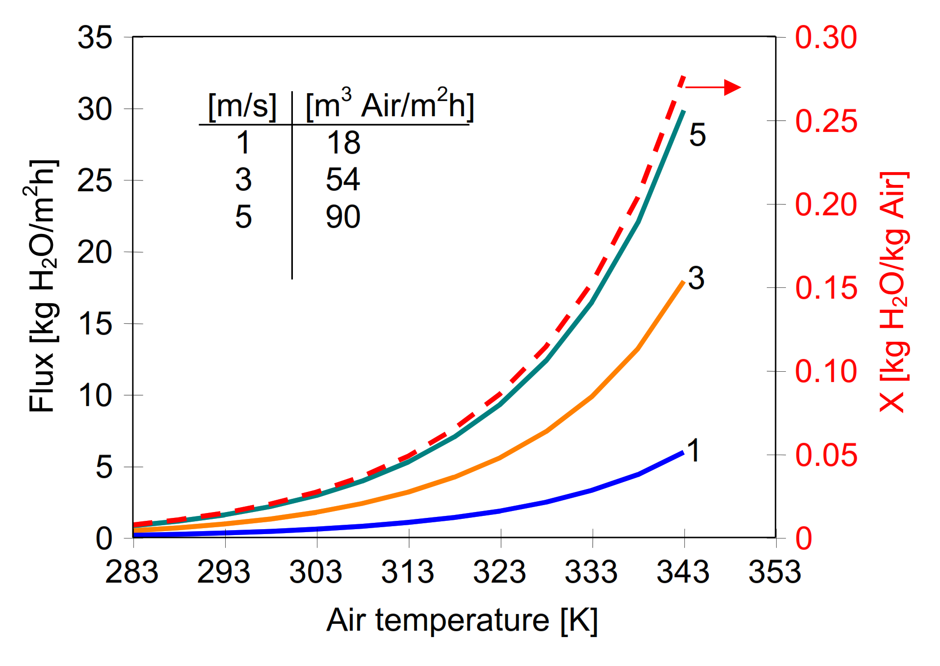
23]. The amount of water vapour that the gas can absorb is small and increases with temperature, e.g., for air from 12.5 to 40.8 g/m3 with a temperature change from 293 to 313 K. This means that for a temperature of 313 K, the evaporation of 10 kg/h of water requires the supply of air to the module in the amount over 245 m3 (0.068 m3/s). In the tested industrial modules, due to high flow resistance, the gas flows used were much smaller and, as a result, the gas quickly reached the saturation state, which significantly reduces the SGMD efficiency. For instance, in [4], for the Celgard Liqui-Cel® Extra-Flow module with an area of 1.4 m2, the permeate flux of 0.5 L/m2h was obtained. The efficiency at a level of 0.1 L/m2h was obtained for a similar large module in work [23]. In this case, this was due to the fact that the permeate flux was only calculated by measuring the difference in gas humidity at the inlet and outlet of the module. Meanwhile, during tests in the SGMD installation with a vapour condenser, it was repeatedly found that the amount of water sweep by the gas from the module was greater than that resulting from the change in gas humidity [5,17,22]. This was explained in [22,23], where it was shown that after the gas is saturated, water vapour condenses and is removed from the module in the form of a mist. These observations were also confirmed in tests with the use of the industrial module [4,6].
A large evaporation surface can be obtained by using capillary modules [1,4,23]. However, in this case it is difficult to maintain a uniform gas flow between the capillaries, especially for higher packing density of the membranes [10,24]. The conclusions from these works are similar to those obtained during tests of DCMD capillary modules, the efficiency of which increased significantly when the arrangement of capillaries ensured static mixing [25]. The best conditions for mass transport in the MD module can be obtained by using cross-flow of the feed and permeate streams [14], which was successfully applied in the construction of a small SGMD installation proposed for freshwater production in remote area [1]. However, it can be expected that in large modules, e.g., with a capillary length of 1 m, the cross-flow of gas stream will cause the “sail effect”. This effect for higher gas flow velocities (e.g., 5 m/s) may, due to increased stresses, cause the capillaries to break at the point of their attachment to module head. For this reason, the design of SGMD modules should ensure low gas flow resistance for its high flow velocities [4]. Such a possibility is given by the proposed open SGMD module design, where, additionally, flexible mounting of the capillary bundles can be used, which should limit the influence of the “sail effect”.
In the modules with shell, both the temperature of the streams and the feed concentration change along the module, which causes a decrease in the efficiency of the MD process [15]. Uniformity of parameters along the entire surface of the capillary membranes was obtained in the MD process using submerged DCMD modules [7]. Worthy of note, similar conditions can be achieved in the case of SGMD by using modules with membranes loosely placed inside large chambers with natural convection or forced air flow generated by fans. Due to the significant polarization on the gas side, the use of fans increasing the gas flow velocity should significantly increase the efficiency of the process [15]. In the SGMD process, the use of the feed flow between capillaries is also possible. Indeed, it was carried out in the tests of 30 cm long module [16]. However, in the case of longer modules, the pressure of the gas flowing inside capillaries will increase significantly, which may increase the costs of gas pumping [4] and its bubbling through the pores of the membrane to the feed [21]. Therefore, in the SGMD process, the feed flow is generally used inside the capillaries [1,4,10,23].
MD module efficiency is strongly affected by the capillaries distribution configurations and membrane packing density [10,24,25]. In the proposed open capillary modules, the packing density of the membranes can be reduced, e.g., for membranes with a diameter of 2.6 mm spaced every 1 cm it would be 52 m2/m3. This value is several times lower than the value of 293 m2/m3 in Celgard Liqui-Cel® Extra-Flow module, which did not allow to obtain good conditions for the SGMD process [4]. The advantage of reducing the packing density is facilitated gas flow. Moreover, in a hot, sunny remote area, a large chamber with membranes could also function as a heat exchanger for air heating, which would significantly simplify the construction of the installation. In the presented work, the effectiveness of the SGMD process implemented in a capillary module without an external shell was tested. The aim of the research was to determine the influence of the process parameters on the level of real efficiencies of SGMD; hence, a module with a length similar to industrial modules was applied. Additionally, it was assessed whether, instead of feed pre-heating inside an external heat exchanger, it is possible to evaporate the water using only energy taken from the air flowing in the module.

Theory

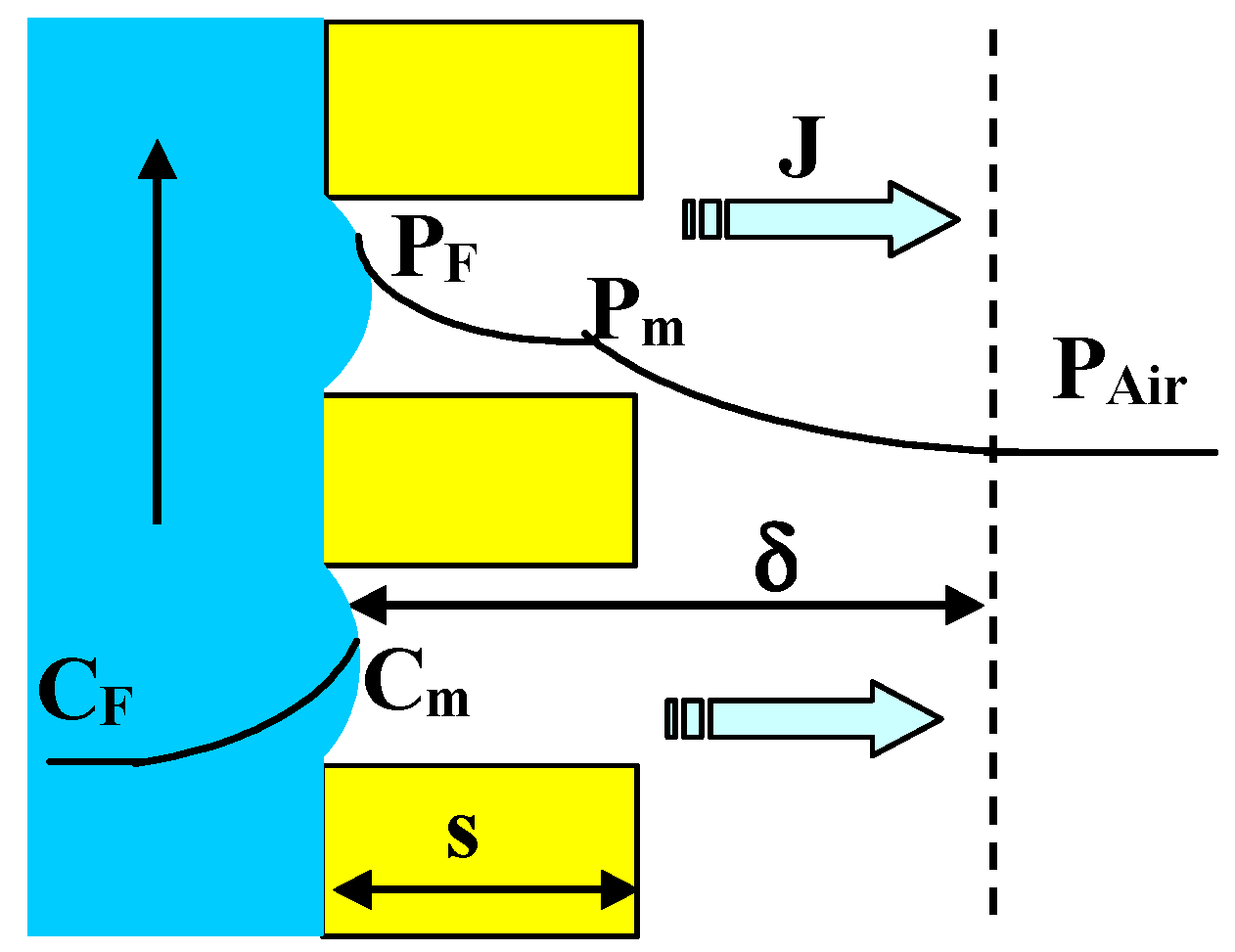
The pores of the hydrophobic membranes applied in the SGMD process are non-wetted, and the feed evaporates from the feed/gas interface created inside the pores. The driving force for the water evaporation is created by a difference between the partial pressure of water vapour (in equilibrium with liquid feed), and its value in the air surrounding the membranes (Figure 1). The obtained permeate flux is proportional to the driving force, which is usually expressed by the application of mass transfer coefficient (Km) [17,22]:
J = K m ( P F P Air ) = K m Δ P
where PF and PAir correspond to the saturated vapour pressure above the evaporation surface and the vapour pressure in the gas (air) stream, respectively.
The partial pressure of water vapour is strongly affected by the liquid temperature, and its value increases exponentially with increasing feed temperature, which can be expressed by the following equation [26]:
P F T = exp 8.07131 1730.63 233.42 + T
where the units of T and PF are °C and mmHg, respectively.
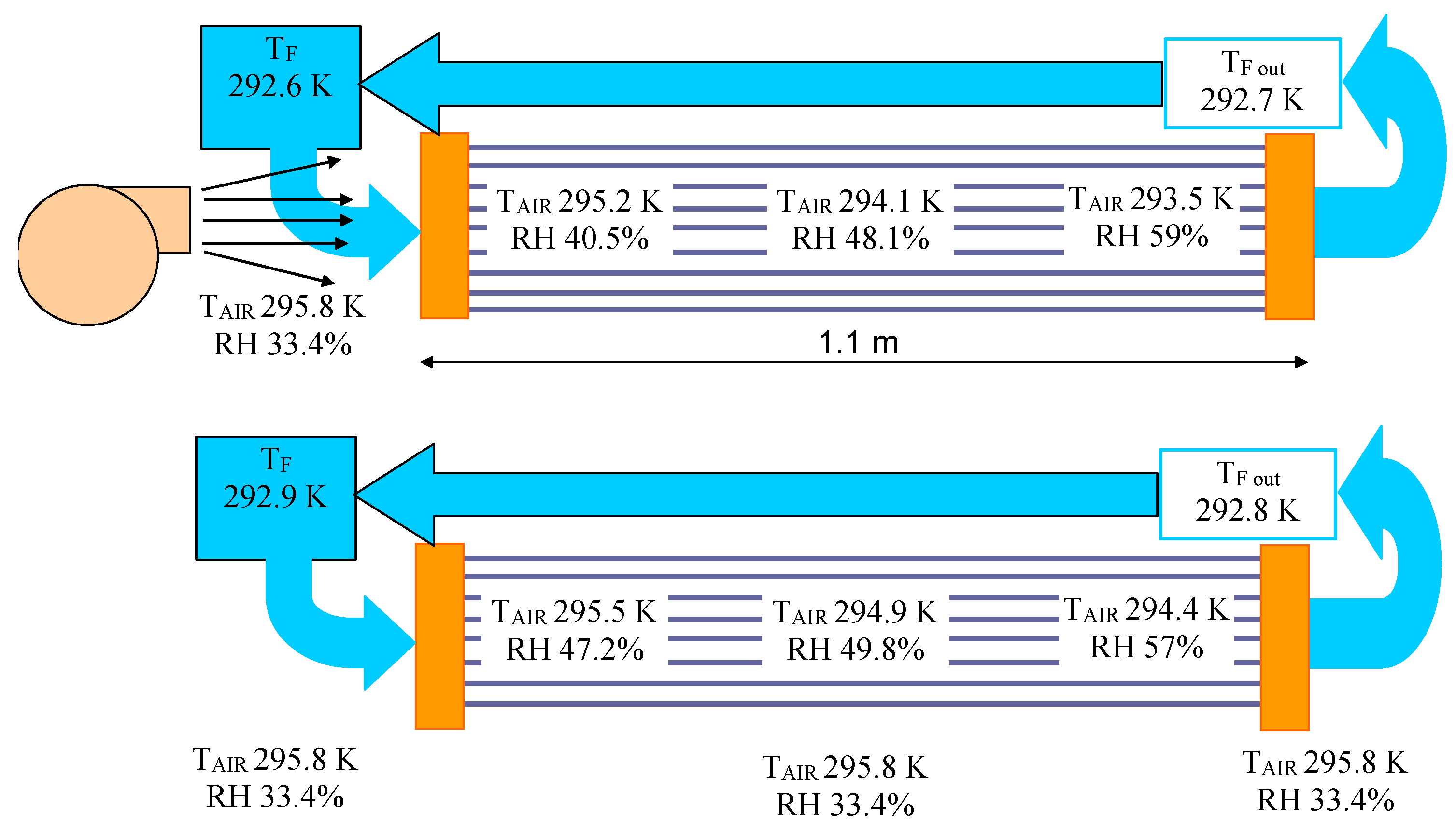
During the streams flowing inside the SGMD module, the value of driving force may change [6,15]. The water evaporation increases the solutes concentration in the feed (Figure 1—Cm) which, in turn, decreases the PF value. Moreover, the gas temperature and humidity fast increases, which strongly affects the SGMD module performance [4,26].
The vapour diffusion across the membrane pores creates the resistance for mas transfer [27]. The Knudsen or molecular diffusion mechanism influences, in a different degree, on this resistance due to a pore size distribution and the process conditions (e.g., temperature level). Taking these parameters into account, the Km coefficient is expressed in the form [17,18,22]:
K m = ε χ s M RT m D WA
with the following parameters: porosity (ε), thickness (s), tortuosity (χ), molecular mass of water (M), gas constant (R), membrane temperature (Tm), and effective diffusion coefficient (DWA). In the case of membrane with the pores below 0.1 μm the effective diffusion is dominated by the Knudsen diffusion [6,22].
In the case when the water is evaporated into the ambient air, a viscous boundary layer is formed above the evaporation surface through which the diffusion of water vapour takes places [10]. The rate of liquid volume change evaporated from the wet surface under the isothermal conditions can be determined using Fick’s law [11]:
dV dt = D   A   M δ   ρ   R   T P F P Air
where D is the diffusion coefficient of liquid particles in the air, A is the liquid surface area available for evaporation, δ is the thickness of viscous boundary layer, ρ is a density of liquid.
An important point which should be noted is that the thickness of the viscous boundary layer formed above the membrane surface can be reduced by increasing turbulence in the gas flow [15]. However, this method cannot change the value of membrane thickness (s), which contributes to the value of δ (Figure 1); hence, the thickness of the membrane has a significant effect on the SGMD process efficiency [14]. Moreover, the value of PAir is associated with air humidity, expressed e.g., by relative humidity (RH), thus, water evaporation increasing a value of the humidity also decreases the evaporation rate. For this reason, the process efficiency is limited in the modules with shell, because a value of the relative humidity of the air in the SGMD module rapidly increases even for high flow rates of air [22,27].
The maximal content of water vapour in air at given temperature is expressed by following equation [10,22]:
X = 0.622 P S P atm P S
where PS is water vapour pressure in saturated air and Patm is atmospheric pressure.
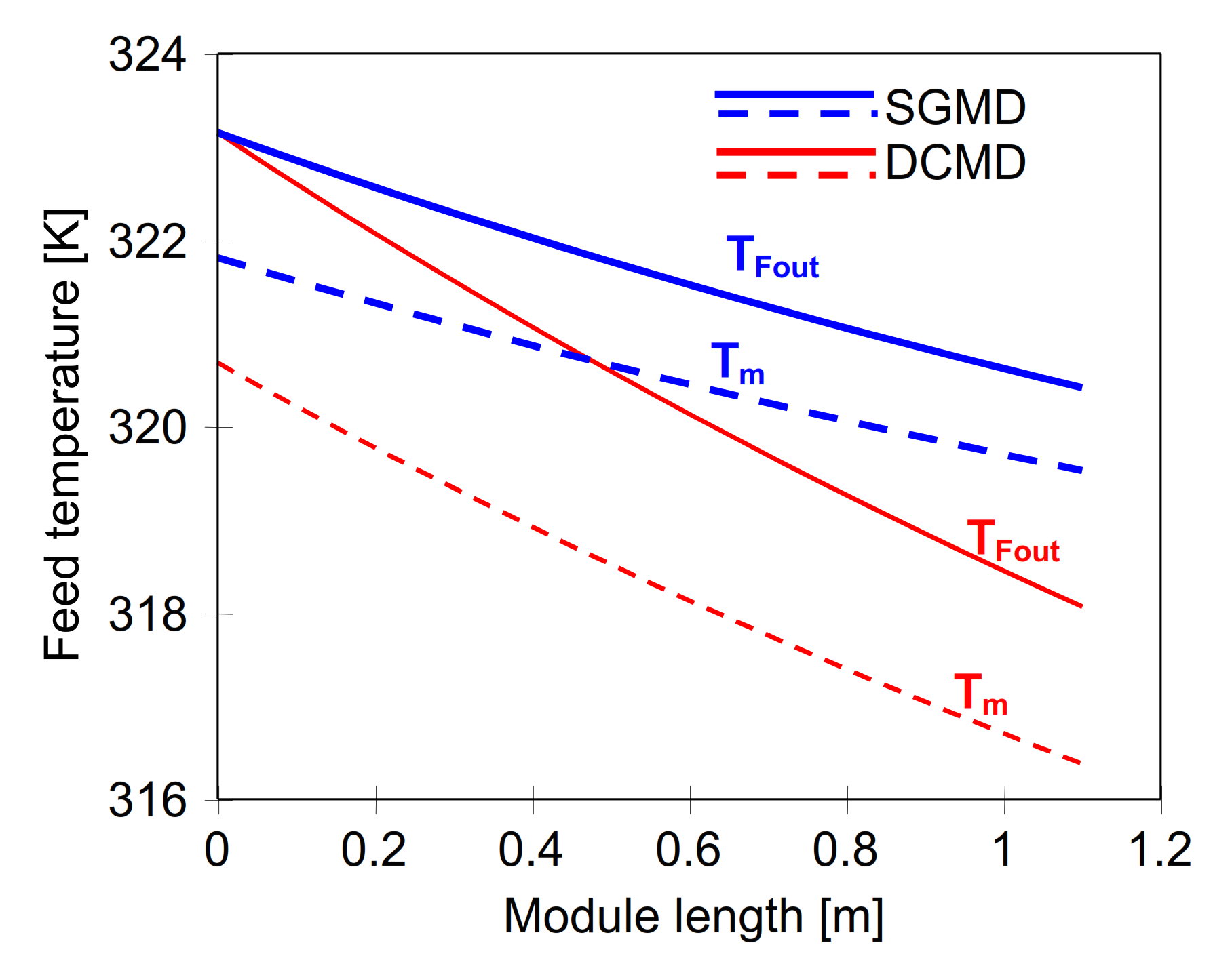
Evaporation is an energy intensive process, therefore, the transport of heat to the interface is the rate-limiting step for the evaporation of liquids into an inert gas. Depending on the membrane installation design and process conditions, the temperature in the gas phase near the liquid–gas interface can be higher or lower than that of the liquid (Figure 2). The application of feed temperature higher than the air temperature allows to increase the driving force of process, hence, pre-heating of feed (Figure 2b) is usually realised in SGMD process [4,14,15,18]. In this case, the limitation is a small amount of water vapour that caused the saturation of the air, which can lead to unfavourable condensation of vapour inside the membrane module [22,26]. The vapour condensation on the membrane surface can be avoided when the modules without an external shell will be used, which also allows to curry out the evaporation without heating of the feed (natural evaporation). In this case, the bulk temperature of the air is higher than the temperature of the evaporating feed [4,15].
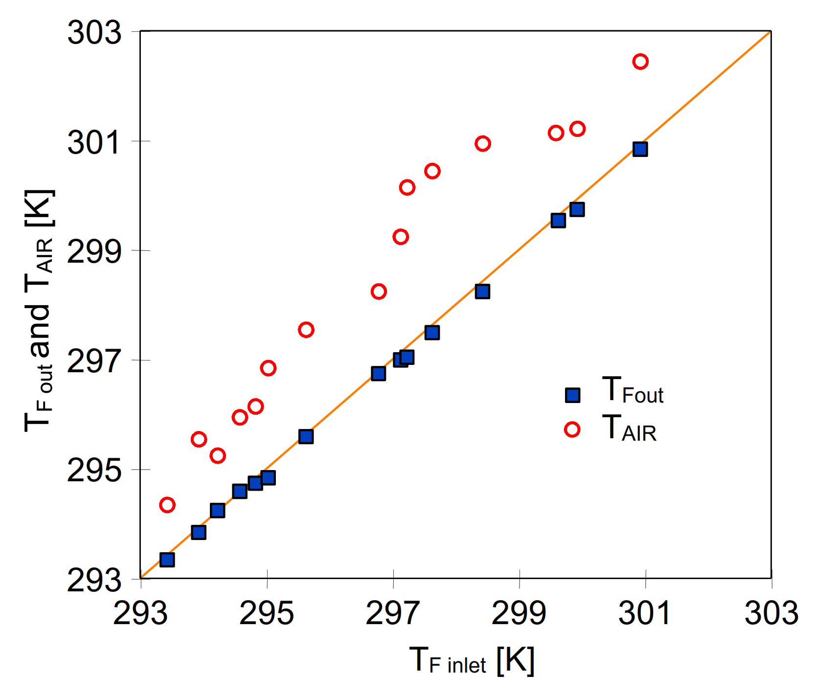
A temperature profile without feed heating is presented in Figure 2a. The energy for evaporation (QV) can only be taken from the gas phase (QA); therefore, the water temperature is quickly aligned to the constant value due to a larger thermal conductivity and the temperature gradient in liquid is negligible. The heat transfer is described by the following equations [9,28]:
QV = J ∆HV
QV = QA = h (TAir − Tm)
where ∆HV is the latent heat of water vapour evaporation and h is the convective heat transfer coefficient (on the air side). When the feed is heated, a part of the feed energy is lost by conductivity (Figure 2b, QC) into the air [26]:
QC = H (TF − TAir)
where H is the overall heat transfer coefficient.
The thermal efficiency (E) of MD process can be determined from the following relationship [9]:
E = QV/(QV + QC)
The value of convective heat transfer coefficient can be calculated from the Nusselt number estimated from following correlation [28]:
Nu = h   d h λ = 4.36 + 0.036 Pe d h L 1 + 0.0011 Pe d h L 0.8
where Nu is Nusselt number, Pe is the Peclet number, L—length of channel (e.g., membrane capillary), dh—hydraulic diameter, λ—heat conductivity coefficient. The remaining model equations applied for calculation of submerged MD modules were presented in work [7].

2. Materials and Methods

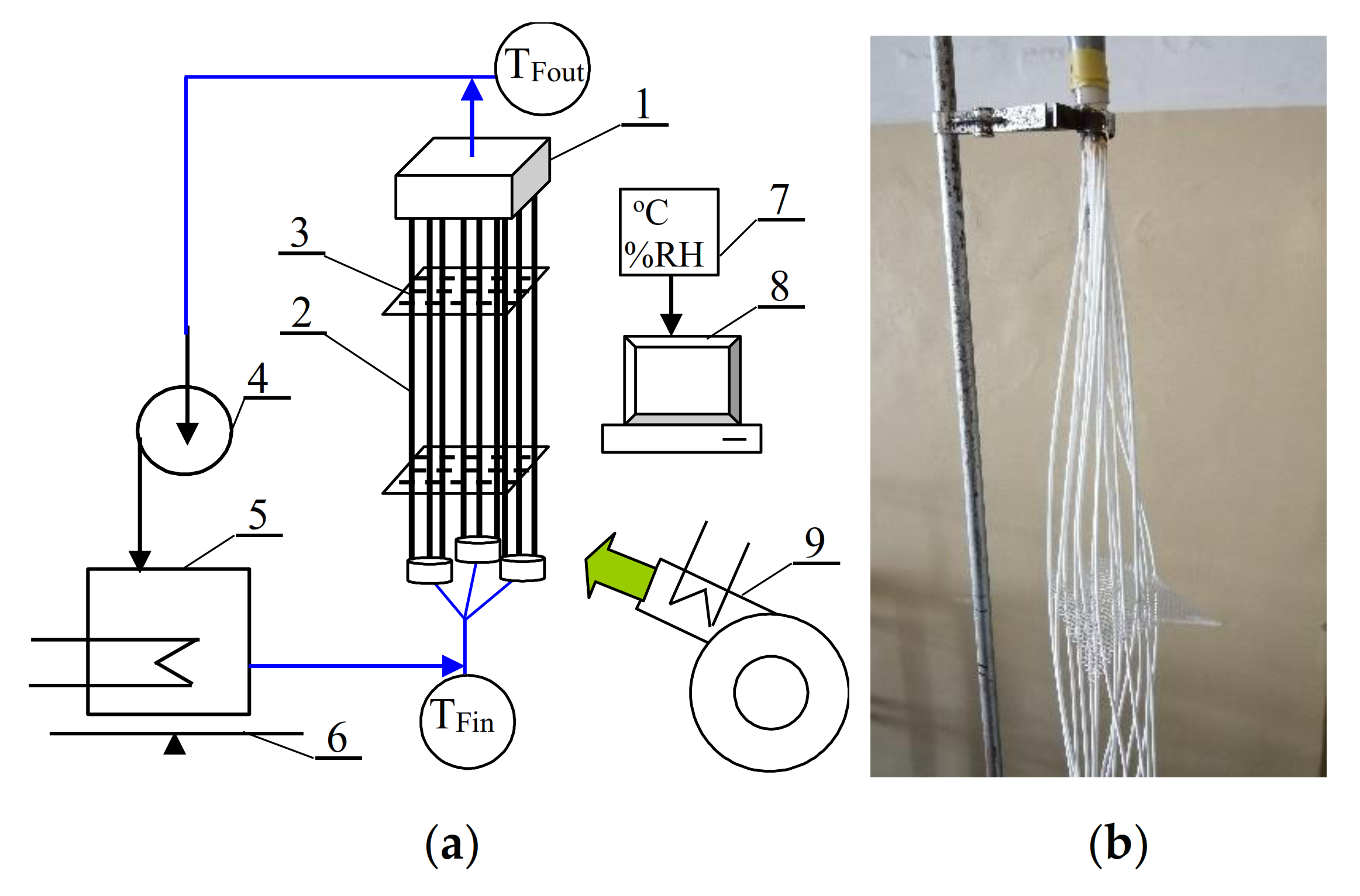
The studies of open capillary modules applied for SGMD were carried out using an installation presented in Figure 3. During experiments with feed pre-heating the feed tank was immersed inside a water thermostat, which allowed to control the feed temperature.
The commercial hydrophobic K1800 polypropylene capillary membranes, manufactured for microfiltration (Euro-Sep, Warszawa, Poland), were used for the studies of membrane evaporation. A module was equipped with 16 capillary membranes, which were glued on both ends inside the PCV tube (1/2″ diameter). The capillary membranes have the internal diameter of 1.8 mm and outer diameter of 2.6 mm, and the effective length of 1.1 m. The total membranes area calculated for the lumen side amounted to 0.1 m2. The membranes were positioned rectangular in every third mesh of two polypropylene nets. A distance between each capillary membrane was about 1 cm. The obtained module packing fractions was 0.05 and membrane packing density 52 m2/m3.
In [1], a horizontal arrangement of capillary membranes was proposed, which is possible in the case of short capillaries. Filling long horizontal capillaries with water would cause their significant deflection and stress in the places of their attachment, which would increase the risk of capillary breakage. For this reason, in the modules used, the capillaries were mounted vertically, with flexible mounting of the lower head of the module, as schematically shown in Figure 3. This solution enables a capillary bundle wave, which allows eliminating the negative influence of the “sail effect”, which may be important for higher gas flow velocities through the chamber.
In this work, most of the tests were carried out in a room with air circulation caused by the ventilation system, which, for the required multiple air changes per hour, assured the air flow in the range of 0.002–0.005 m/s. Tests were also carried out with air forced by the fan from the bottom to the top of the capillaries. In this case, the gas flow velocity in the lower part of the module was 2.3–2.5 m/s and along the module it decreased to 1.8 m/s in the upper part. The fan did not have rotor speed control, hence, the obtained air flows resulted from the factory efficiency of the fan. Whereas the fan was equipped with an electrical heat element, which made it possible to additionally carry out tests with hot air (313 K). The air flow velocity was measured using electronic anemometer MT-881 (MeasureMe, China).
The feed flowed inside the capillaries (lumen side) during the evaporation experiments. A peristaltic pump was used, and the feed flow rate was equal to 0.1 m/s. The influence of flow velocity (0.1–0.59 m/s) on the evaporation efficiency was additionally investigated.
The total dissolved solids (TDS) of solutions were measured with a 6P Ultrameter (Myron L Company, Carlsbad, CA, USA). This meter was calibrated for measurements as NaCl using TDS/conductivity standard solution (Myron L Company). The air temperature and relative humidity were measured by electronic hygrometer AZ8829 (AZ-Instruments, Kraków, Poland) connected with computer software TRLOG v. 3.4. The feed temperature was measured using electronic thermometers PT-401 with measurement accuracy 0.1 K (Elmetron, Zabrze, Poland).
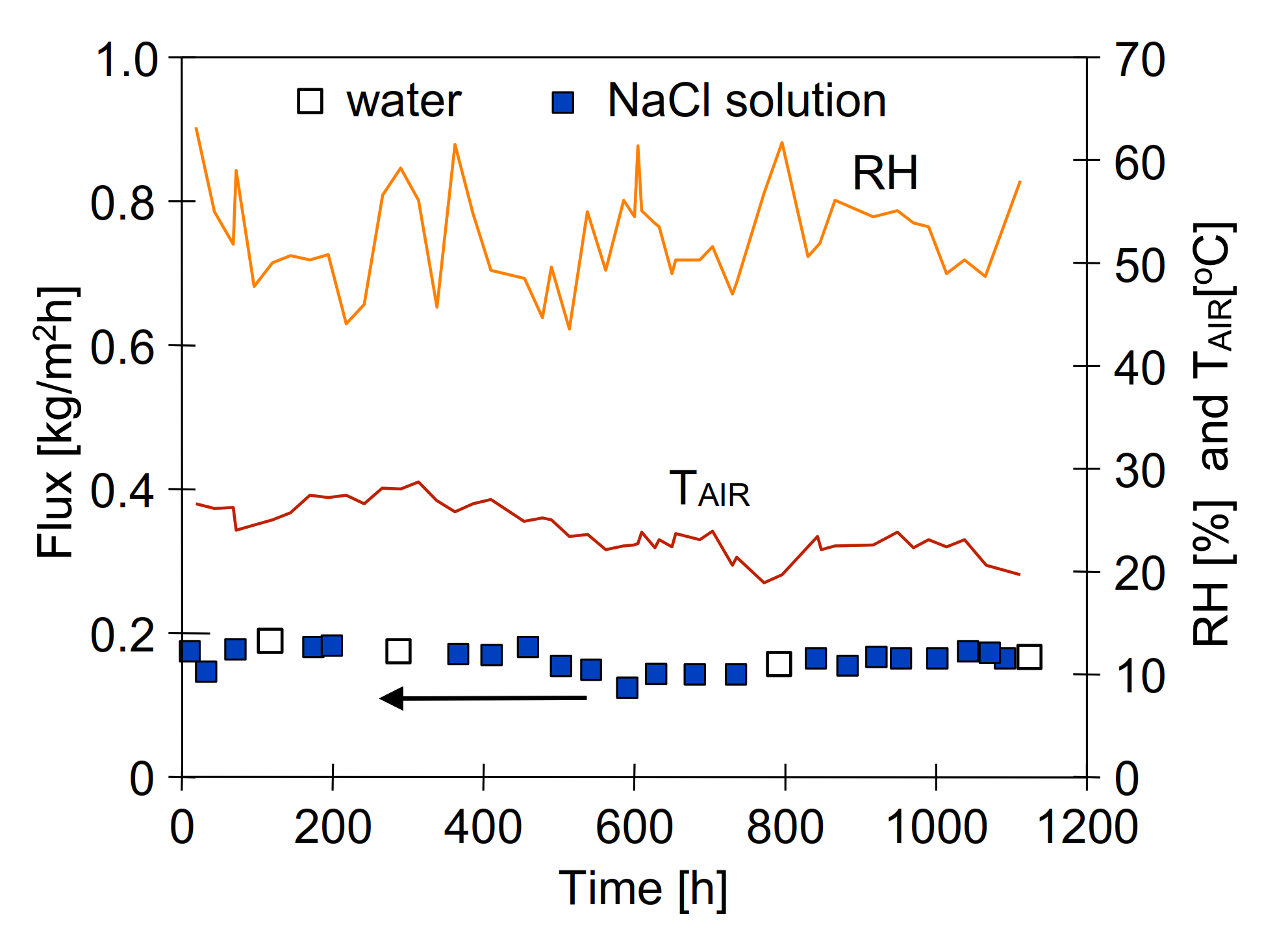
The membrane evaporation tests were carried out using distilled water or NaCl solutions (pure NaCl, Chempur, Piekary Śląskie, Poland) as a feed. The studies was conducted continuously for several months. Indeed, the experiments started in June (summer) and ended in October (autumn). The changes of module efficiency (maximum permeate flux) were measured periodically at established periods using distilled water as a feed. The MD installation was working continuously. The permeate flux was calculated every 20–24 h, based on the decrease of the feed volume.

3. Results

3.1. Influence of Process Parameters on the Permeate Flux

The presented work considers the possibility of implementing the SGMD process in open modules, which are created by bundles of capillaries distributed symmetrically in gas-filled chambers. Open SGMD module can operate in conditions similar to natural evaporation or in chambers with forced gas flow. In the first stage of studies, the operation of the open SGMD module under very low air flow conditions was tested.
The feed temperature is one of the most important parameters in the MD process. The performed tests confirmed that also in the case of open modules, the feed temperature has a significant impact on the SGMD process performance. The results presented in Figure 4 show that increasing the inlet feed temperature from 293 to 323 K resulted in a three–four-fold increase in the permeate flux, which, for 323 K, was equal to 2.4 L/m2h (vF = 0.59 m/s). It is essential to mention that similarly high increases in the process performance were obtained by increasing the feed temperature in traditional SGMD modules [5,17,20].
Water evaporation from the feed causes a significant increase in the concentration of solutes in the boundary layer (Figure 1—Cm). The results obtained during the separation of the solution containing 100–120 g NaCl/L are additionally presented in Figure 4. The noted permeate fluxes were only slightly lower than those obtained for distilled water. Therefore, it can be concluded that such a significant increase of concentration caused only a small decline of the performance, which is a known advantage of the MD process [7,12]. As a result, the MD process can be used not only for the preparation of freshwater from concentrated brines, but also for the concentration of solutions [14,18,29].
In the MD process, solutions can be concentrated up to the saturation state [12]. According to Raoult’s law the vapour pressure decreases with increasing of feed water salinity as follows [30]:
PF = (1 − x) PF0
where PF0 is the vapour pressure of pure water and x is the molar fraction of salt in the water. For example, for almost saturated NaCl solution (5.5 mole/L) with a water concentration of 55.5 mole/L, we have x = 5.5/(55.5 + 5.5) = 0.09, which gives about a 10% decrease in driving force. The decrease in permeate flux obtained with saturated solutions was greater than 20%, which, in addition to reducing water activity, was also influenced by an increase in feed viscosity [31]. It is important to note that, during the MD of concentrated solutions, the feed flow conditions should be ensured to prevent salt crystallization on the membrane surface [12].
In addition, the obtained results (Figure 4) showed a significant influence of the feed flow velocity on the permeate flux. An important point which should be noted is that this effect increased with increasing feed temperature. Indeed, for instance, for TF = 323 K, increasing vF from 0.28 to 0.59 m/s resulted in an increase of the permeate flux by 55% (from 1.55 to 2.4 L/m2h). During the feed flow through the module, due to mass and heat transfer, the feed temperature decreases, which can be reduced by increasing its flow velocity [7,20]. Conducting the SGMD process in small modules and at relatively high flows does not cause significant changes in the feed temperature [26]. Hence, in some studies a slight influence of the feed flow velocity was shown [26,32], which, however, changes when modules with a much larger membrane area are tested [10,17,20].
As stated before, in the presented work, the active length of the membranes in the capillary module was 1.1 m, which allowed to obtain a significant difference in the feed temperature between the inlet and outlet from the module (Figure 5). Similar changes in the feed temperature was presented in [20].
The obtained TFinlet-TFoutlet values increased exponentially with the increase of the TFinlet temperature as the amount of evaporated water also similarly increased (Figure 4). Increasing the feed velocity limited its temperature decline, e.g., from 12 to 4 K when the flow velocity has increased from 0.28 to 0.59 m/s (Figure 5). It should be noted that this stabilizing effect of the feed temperature results not only from the feed velocity but also from the channel cross-sectional area, which determines the ratio of the volumetric feed velocity (L/s) to the membrane area [m2]. In the case of the tested capillary module, it was equal to 0.11 L/s m2 (vF = 0.28 m/s) and 0.24 L/s m2 for the flow velocity of 0.59 m/s. For an example of a plate module with a size of 10 × 10 cm and a channel height of 0.2 cm, at feed velocity of 0.59 m/s, the value of this ratio is equal to 11.8 L/s m2. Such a high value explains the slight changes in the feed temperature when testing such small modules. However, if the length of this plate module will be increased to 1 m, the obtained value will be equal to 0.118 L/s m2. It will result in a significant decline in the feed temperature, which reduces the SGMD efficiency several times, e.g., to the level of 0.3 kg/m2h [15].
It is necessary to mention that the feed flow velocity also has a significant impact on the value of the convective heat transfer coefficient (h), which determines the value of the temperature Tm (Figure 2). The temperature of the evaporation surface determines the vapour pressure at the interface phases (PFFigure 1, and Equation (2)). For the capillary membranes used, the value of the h coefficient can be calculated from the correlation expressed by Equation (10). For TF = 323 K, the obtained h value was 2380 W/m2K (vF = 0.28 m/s) and 2465 W/m2K for vF = 0.59 m/s. The temperature distribution along the module calculated for the vF = 0.59 m/s is presented in Figure 6. The difference in temperature TFout and Tm did not exceed 1 K, which corresponds to the values of the feed temperature profile presented in work [15].
The results of numerical calculations performed for a submerged DCMD module (similar to SGMD module) immersed in the distillate are additionally shown in Figure 6. All parameters from the SGMD module calculations were adopted, however, the air was replaced with distilled water at 293 K. It has been found that the value of the temperature polarization on the feed side is twice as large, which is due to the fact that in the DCMD variant, the membrane is in contact with the cold distillate, and this significantly increases the value of the conducted heat (Figure 2b, QC). As a result, the calculated thermal efficiency of the tested SGMD module, amounting to 68%, decreased to 43% in the case of its operation in the DCMD variant. Similar values of thermal efficiency for DCMD submerged modules were obtained in work [7].
Since the feed temperature decreases as it flows along the module, the module size has the significant impact on the MD process run. Indeed, for small modules, the TF change is insignificant, hence the conversion fluxes (L/m2h) are overestimated and many times greater than those obtained in modules whose area is actually 1 m2 or more [13].

Effect of Gas Flow Rate

The thermal equilibrium between the air and the feed depends not only on the air temperature but also on the evaporation rate which is influenced by the boundary layer conditions (Equation (4)). For this reason, increasing the flow velocity, reducing the thickness of the layer δ [15], has a significant impact on the course of the SGMD process [23]. The reduction of the water vapor concentration at the membrane surface caused by the gas flow increases the value of the vapor pressure difference (dP/dx), which is schematically presented in Figure 7.
Forced convection of gas increases the rate of evaporation [4], which was confirmed by the results presented in Figure 8 (Tests 1 and 2—without feed pre-heating), showing that the permeate flux increased from 0.240 to 0.385 L/m2h (60%) when the fan was started and air was flowing between the capillaries at a velocity of 1.8–2.5 m/s. A similarly large effect of increasing the gas flow velocity was demonstrated in SGMD modules with a shell [20,32]. However, the process efficiencies obtained for such classical modules are presented in a wide range of 0.1–50 L/m2h [4,16,22]. Such different efficiencies result from the fact that the vapour condensation (mist) in the sweep gas significantly increases the efficiency of the tested modules [22,26]. In the studied case (Figure 8), there was no vapour condensation, hence, the use of an open structure made it possible to keep the vapour content in the air below its saturation value (Figure 9). Moreover, the performed measurements showed that the use of the fan reduced the air humidity between the capillaries. The air temperature inside the module also slightly decreased, which confirms that the energy used for the increased evaporation came from the air surrounding the membranes. The higher the air temperature, the more energy is transferred to the evaporation surface, which allowed to significantly increase the efficiency (Figure 8, Tests 3 and 4). The possibility of feed heating by the air surrounding the membranes is presented in the next Section.
In the SGMD process assumption, the air flowing out of the module should not be saturated, which prevents vapour condensation in the module channels [5]. Notwithstanding, in the SGMD module, conditions are often created for supersaturation of the gas, which causes the formation of water droplets on the permeate side [22]. In this case, a significant part of the water evaporated from the feed is discharged from the module in the form of a mist, which significantly increases the calculated permeate flux [5,17,22,26]. The maximum amount of water vapour that the air can contain at a given temperature was calculated using Equations (2) and (9) and is shown in Figure 10. The amount above 0.1 kg H2O/kg air increases rapidly, similar as does the water vapour pressure, for temperatures above 323 K. The obtained values were converted into the maximum flux that would result in air saturation at a given temperature. The results of the calculations performed show that, e.g., for a permeate flux of 30 L/m2h, the air supply (343 K) should be 90 m3/h per 1 m2 of membranes. For the example flat channel dimension, 1 m wide and 5 mm high; this would correspond to a flow velocity of 5 m/s. Reducing the flow velocity to 1 m/s would allow about 5 kg/h of evaporating water to be removed from 1 m2 of membranes. It follows that obtaining higher efficiencies in the SGMD process requires the use of high gas flow velocities, which is difficult to obtain in large modules due to the arising significant air flow resistance [4]. The proposed open modules, due to the use of a lower packing factor of the membranes, would facilitate the use of higher air flow velocities. For the tested module with air flow along the capillaries (cross-section 5 × 5 cm) with a speed of 2 m/s, an air flow of 18 m3/h was obtained, with no visible effects of waving membranes.
The results shown in Figure 8 demonstrated that besides the gas flow velocity, the feed temperature also has a great influence on the SGMD performance. Increasing its value from 294 to 302 K resulted in an increase in the permeate flux from 0.38 to 0.95 L/m2h. If temperature TF < TAir, the gas will be the energy source for water evaporation.

3.2. Feed Heating by Sweeping Gas

The heat of water vaporization is high (2500 kJ/kg), while the specific heat of air is low (1.005 kJ/kg), hence, its use as a heating medium requires forcing large volumes of gas through the module. In classic modules with a shell, which are characterised by a high degree of membrane packing density, it is not possible to obtain large gas flows due to a significant increase in flow resistance [4]. Open capillary modules allow for the implementation of SGMD in conditions of a significant excess of flowing gas in relation to the surface of the membranes, which makes it possible to use air to heat the feed. This variant is schematically shown in Figure 2a. The results presented in Figure 8 and Figure 9 show that energy transfer from air to the membrane can be accomplished for both natural and forced convection.
In the MD process, the permeate volume obtained in relation to the feed is small, therefore, in MD installations multiple feed recirculation is used [33]. In the case when the external heat exchanger (feed pre-heating) is not used, the water evaporation in the module cool-down feed, but simultaneously the air surrounding the installation heats the feed. As a result of multiple recirculation, an equilibrium temperature is achieved, and the TFinlet was closed to the TFout temperature (Figure 11). A variant of operation without feed pre-heating was used during summer studies, e.g., obtaining the feed temperature over 300 K on hot days (TAir = 302 K), whereas the feed temperature along the module did not undergo changes. The tests were carried out without a fan working and the permeate flux was in the range of 0.2–0.3 L/m2h. This noteworthy result indicates that the process performance depends not only on the temperature but also on the humidity of the air surrounding the installation, which changed during test in the range 49–57%.
The permeate flux obtained for almost a constant feed temperature allows to determine the value of Km coefficient from Equations (1) and (3). This part of studies was carried out using distilled water as a feed, and the value of Km = (1.3 +/− 0.15) × 10−4 L/m2h Pa was obtained. The air parameters changes in the range: TAir = 299–300.8 K and RH = 45–53% during this study. More than 10 times lower values (1 ÷ 8 × 10⁻⁵ L/m2h Pa) were obtained for industrial modules in [5]. This value increased with the increase of the gas flow velocity, which confirms the conclusion from Figure 10 that the gas is saturated quickly in large modules with shell [4,23]. As a result, the main component of the mass transport resistance is on the gas side, in contrast to the tested open module, where the parameters of the membranes determine the evaporation rate.
The results presented in Figure 8 indicated that the increase in SGMD performance can be obtained by increasing the gas flow velocity between the capillary membranes. Additionally, for the variant with forced gas flow, it is possible to heat the feed with the hot gas, which allows to increase the feed temperature and increase the performance of the process several times. In the tested case, the temperature of the air flowing along the membranes varied from 313 K (module bottom) to 299 K (the top of the module). As a result, the permeate flux was equal to 0.72 L/m2h when the feed temperature increased to 300.6 K and 0.95 L/m2h for TF = 302.6 K (Figure 8). For comparison, the temperature distribution along the module for the case without air heating was also shown in Figure 9. In this case, the feed temperature will be lower than the air temperature, it tends to the wet bulb temperature, which lowers the vapour pressure in the pores of the membrane and, as a result, the evaporation efficiency is lower. In the case of small laboratory installations, it should be taken into account that not only the air parameters (TAir, RH) but also the installation parameters (e.g., feed volume, tank, and tubing wall surface) affect the test result. The influence of the ratio of the feed volume to the membrane area on the stabilization of the installation operation is shown in Figure 12. It is worth noting that, in the case of starting large industrial modules, the SGMD stabilization period was about 2 h [23].
Heating the feed with the hot gas is a method that provides an to increase energy efficiency—as, once equilibrated, all heat is used for evaporation (Figure 2a). In contrast, when the module is fed with hot water, only part of the energy from the feed goes to evaporation (Figure 2b). In the case of the tested K1800 capillary membranes, a module with an area of 1 m2 for vF = 1.22 m/s supplies 0.5 kg/s of the feed, i.e., for TF = 333 K, the feed energy is equal to 126 kW. Assuming that the permeate flux is 10 kg/m2h [7], only 6.9 kW is used for evaporation (∆H = 2500 kJ/kg). The temperature at the outlet from the module for these conditions is about 10 K lower, which ensures a decrease in energy by 21 kW, i.e., a thermal efficiency of 33%.
In SGMD modules, the separation of the membrane by a gas layer limited heat loss and the thermal efficiency increased to 50–75% [4]. This value depends mainly on the temperature of the feed. Considering only the drop in temperature of the feed flowing through the Celgard Liqui-Cel module (1.4 m2) [4], the energy consumption for water evaporation were calculated and presented in Figure 13. As the temperature of the feed increases, the efficiency increases, but also the energy consumption approaches the minimum value of 694 kWh/m3 (calculated for ∆H = 2500 kJ/kg).
In the SGMD variant with the feed pre-heating (Figure 13), most of the energy consumed resulted from the drop in the temperature of the feed in the module. In the proposed open-module solution, energy for water evaporation is taken from the environment around the installation. The air heated by the sun flows between the capillaries and transfers its energy to the surface of the membranes. In this case, the energy consumption in the process will be mainly due to the operation of the fans. However, even large fans with a capacity of several thousand m3/h consume much less energy compared to the heat of water vaporization [34].
The motor power of the fan used in addition to capacity is also influenced by the flow resistance of air inside the chamber. Importantly, the determination of their values for the air flow in the open module requires further research. However, considering that the flow resistance through the ventilation grille is in the order of 20–40 Pa, it can be assumed that the flow resistance through a chamber with a cross section of 0.5 × 1 m in which 5 rows of capillaries are arranged, each of which is located 1–2 cm from the other, should not exceed 500 Pa. Sample fan GMT-R-60 series equipped with a 340 W motor and capacity decreasing from 540 to 400 m3/h with increasing flow resistance from 230 to 1000 Pa [34] should be appropriate for the open module in which 250 capillaries with a length of 1 m were installed (area of 1.4 m2). This installation allows for the evaporation of a similar amount of water (Figure 8) as obtained in the Celgard Liqui-Cel module [4], which, however, consumed many times more energy (Figure 13).

3.3. Long-Term Studies

The MD process is most often proposed for water desalination, but other applications such as concentration of solutions are also contemplated. One of the examples is the use of SGMD to concentrate solutions of glycerol [29], sugar [32], or fruit juices [18]. In the case of solution concentration, there is no need to use a vapour condenser, which significantly simplifies the installation and allows the use of the open SGMD variant of the modules without the need to achieve a state of supersaturation of the vapour in the sweeping gas (inside condenser). The effectiveness of water evaporation in open capillary modules without the use of feed pre-heating has been proven in long-term studies.
The studies of SGMD were carried out for 4 months corresponding to over 1100 h of module work using distilled water with 5 g/L of NaCl as a feed. After such period of operation, the module performance was changed only slightly (Figure 14). Fluctuations of maximum permeate flux with time presented in this figure mainly resulted from the changes of ambient air temperature and relative humidity. The data presented in Figure 14 were calculated as the averages for each day. In order to achieve the operation conditions close to the natural ones (outdoor), the installation was left in a room with a slightly open window, which caused the changes of parameters of installation operation depending on weather conditions and time of day. The studies were started on summer (average air temperature 299 K) and were ended on autumn, when the average air temperature dropped to 295 K. The increase in humidity results not only from rainfalls, but also from increasing mean air temperature, which intensifies the water evaporation from soil and plants. It is worth noting that despite significant changes in air parameters, the obtained average daily performance was at a similar level. It also shows that the capillary membranes used were not wetted despite their long service life. It is well known that the membrane wetting is a major operational issue in the MD process. This problem also applies to the SGMD variant, as a result of which, the permeate flux decreased by 40% already after 140 h of the process run [16].
To simplify the installation, the long-term tests were carried out without air flow forced by fan. However, the results presented in Figure 8 indicate that the use of fans would allow the permeate flux to be increased to a level of 0.3 L/m2h. For the membrane packing density 52 m2/m3 used in the work, for an exemplary chamber 2 m wide and 5 m long, an installation with an area of over 500 m2 would be obtained, which would allow for the evaporation of 150 L/h of water. The analysis of the impact of the packing degree on the gas velocity distribution presented in [24] shows that a two–three-fold increase in the packing density should not significantly affect the operation of the installation and the capacity of 500 L/h should be available for an example installation without feed pre-heating.

4. Conclusions

The performance obtained in the conducted research was similar to the SGMD results presented in the literature obtained for industrial membrane contactors, which indicates that the proposed open capillary modules are an interesting alternative to classic modules with shell.
The conducted tests confirmed that, in the case of industrial SGMD installations, a permeate flux at a level of a few L/m2h should be expected. For this performance, in order to prevent vapour condensation in the module the air stream in the range of 10–20 m3/h per 1 m2 of membranes will be required. Providing such a large gas flow in classic modules with a shell would significantly increase the flow resistance, which can be limited using open capillary modules with lower membrane packing density.
An important point that should be noted is that the application of the capillary modules without an external shell allows to realise this process without feed pre-heating (natural evaporation) with the permeate flux at a level of 0.15–0.3 L/m2h. In the case when hot air (313 K) heating the membrane surface the water evaporation increased to 0.95 L/m2h for feed temperature equal to 302.6 K.
An increase of the feed temperature from 295 K to 330 K allowed to increase the evaporation performance from 0.3 to 2.4 L/m2h for very low gas flow. The evaporation efficiency increased about 60% when gas flow increased to 1.8–2.5 m/s.

Funding

This research was funded by National Science Centre, Poland, grant number 2018/29/B/ST8/00942.

Institutional Review Board Statement

Not applicable.

Informed Consent Statement

Not applicable.

Data Availability Statement

The data presented in this study are available upon request from the corresponding author. The data are not publicly available due to the institutional repository being under construction.

Conflicts of Interest

The author declares no conflict of interest. The funders had no role in the design of the study; in the collection, analyses, or interpretation of data; in the writing of the manuscript, or in the decision to publish the results.

References

  1. Li, G.; Lu, L. Modeling and performance analysis of a fully solar-powered stand-alone sweeping gas membrane distillation desalination system for island and coastal households. Energy Convers. Manag. 2019, 205, 112375. [Google Scholar] [CrossRef]
  2. Janajreh, I.; Suwwan, D.; Hashaikeh, R. Assessment of direct contact membrane distillation under different configurations, velocities and membrane properties. Appl. Energy 2017, 185, 2058–2073. [Google Scholar] [CrossRef]
  3. Siyal, M.I.; Lee, C.-K.; Park, C.; Khan, A.A.; Kim, J.-O. A review of membrane development in membrane distillation for emulsified industrial or shale gas wastewater treatments with feed containing hybrid impurities. J. Environ. Manag. 2019, 243, 45–66. [Google Scholar] [CrossRef] [PubMed]
  4. Evans, L.; Miller, J. Sweeping Gas Membrane Desalination Using Commercial Hydrophobic Hollow Fiber Membranes; Sandia National Laboratories: Albuquerque, NM, USA, 2002.
  5. Boukhriss, M.; Ben Hmida, M.B.; Maatoug, M.A.; Zarzoum, K.; Marzouki, R.; Ben Bacha, H. The design of a unit sweeping gas membrane distillation: Experimental study on a membrane and operating parameters. Appl. Water Sci. 2020, 10, 1–14. [Google Scholar] [CrossRef] [Green Version]
  6. Karanikola, V.; Corral, A.F.; Jiang, H.; Sáez, A.E.; Ela, W.P.; Arnold, R.G. Sweeping gas membrane distillation: Numerical simulation of mass and heat transfer in a hollow fiber membrane module. J. Membr. Sci. 2015, 483, 15–24. [Google Scholar] [CrossRef]
  7. Gryta, M. The Application of Submerged Modules for Membrane Distillation. Membranes 2020, 10, 25. [Google Scholar] [CrossRef] [PubMed] [Green Version]
  8. Duong, H.; Cooper, P.; Nelemans, B.; Cath, T.Y.; Nghiem, L.D. Evaluating energy consumption of air gap membrane distillation for seawater desalination at pilot scale level. Sep. Purif. Technol. 2016, 166, 55–62. [Google Scholar] [CrossRef] [Green Version]
  9. Rivier, C.; García-Payo, M.; Marison, I.; von Stockar, U. Separation of binary mixtures by thermostatic sweeping gas membrane distillation I. Theory and simulations. J. Membr. Sci. 2002, 201, 1–16. [Google Scholar] [CrossRef]
  10. Li, G.-P.; Zhang, L.-Z. Laminar flow and conjugate heat and mass transfer in a hollow fiber membrane bundle used for seawater desalination. Int. J. Heat Mass Transf. 2017, 111, 123–137. [Google Scholar] [CrossRef]
  11. Shokri-Kuehni, S.M.S.; Rad, M.N.; Webb, C.; Shokri, N. Impact of type of salt and ambient conditions on saline water evaporation from porous media. Adv. Water Resour. 2017, 105, 154–161. [Google Scholar] [CrossRef] [Green Version]
  12. Edwie, F.; Chung, T.-S. Development of simultaneous membrane distillation–crystallization (SMDC) technology for treatment of saturated brine. Chem. Eng. Sci. 2013, 98, 160–172. [Google Scholar] [CrossRef]
  13. Elsheniti, M.B.; Elbessomy, M.O.; Wagdy, K.; Elsamni, O.A.; Elewa, M.M. Augmenting the distillate water flux of sweeping gas membrane distillation using turbulators: A numerical investigation. Case Stud. Therm. Eng. 2021, 26, 101180. [Google Scholar] [CrossRef]
  14. Shirazi, M.M.A.; Kargari, A.; Bastani, D.; Soleimani, M.; Fatehi, L. Study on Commercial Membranes and Sweeping Gas Membrane Distillation for Concentrating of Glucose Syrup. J. MSR 2020, 6, 47–57. [Google Scholar] [CrossRef]
  15. Perfilov, V.; Fila, V.; Marcano, J.S. A general predictive model for sweeping gas membrane distillation. Desalination 2018, 443, 285–306. [Google Scholar] [CrossRef]
  16. Mousavi, S.A.; Aboosadi, Z.A.; Mansourizadeh, A.; Honarvar, B. Surface modified porous polyetherimide hollow fiber membrane for sweeping gas membrane distillation of dyeing wastewater. Colloids Surf. A Physicochem. Eng. Asp. 2020, 610, 125439. [Google Scholar] [CrossRef]
  17. Gao, L.; Zhang, J.; Gray, S.; Li, J.-D. Experimental study of hollow fiber permeate gap membrane distillation and its performance comparison with DCMD and SGMD. Sep. Purif. Technol. 2017, 188, 11–23. [Google Scholar] [CrossRef]
  18. Bagger-Jørgensen, R.; Meyer, A.S.; Pinelo, M.; Varming, C.; Jonsson, G. Recovery of volatile fruit juice aroma compounds by membrane technology: Sweeping gas versus vacuum membrane distillation. Innov. Food Sci. Emerg. Technol. 2011, 12, 388–397. [Google Scholar] [CrossRef]
  19. Criscuoli, A. Thermal Performance of Integrated Direct Contact and Vacuum Membrane Distillation Units. Energies 2021, 14, 7405. [Google Scholar] [CrossRef]
  20. Safi, N.N.; Ibrahim, S.S.; Zouli, N.; Majdi, H.S.; Alsalhy, Q.F.; Drioli, E.; Figoli, A. A Systematic Framework for Optimizing a Sweeping Gas Membrane Distillation (SGMD). Membranes 2020, 10, 254. [Google Scholar] [CrossRef]
  21. Khayet, M.; Cojocaru, C.; Baroudi, A. Modeling and optimization of sweeping gas membrane distillation. Desalination 2012, 287, 159–166. [Google Scholar] [CrossRef]
  22. Zhao, S.; Feron, P.H.; Xie, Z.; Zhang, J.; Hoang, M. Condensation studies in membrane evaporation and sweeping gas membrane distillation. J. Membr. Sci. 2014, 462, 9–16. [Google Scholar] [CrossRef] [Green Version]
  23. Abejón, R.; Saidani, H.; Deratani, A.; Richard, C.; Sánchez-Marcano, J. Concentration of 1,3-dimethyl-2-imidazolidinone in Aqueous Solutions by Sweeping Gas Membrane Distillation: From Bench to Industrial Scale. Membranes 2019, 9, 158. [Google Scholar] [CrossRef] [Green Version]
  24. Huang, S.-M.; Chen, Y.-H.; Yuan, W.-Z.; Zhao, S.; Hong, Y.; Ye, W.-B.; Yang, M. Heat and mass transfer in a hollow fiber membrane contactor for sweeping gas membrane distillation. Sep. Purif. Technol. 2019, 220, 334–344. [Google Scholar] [CrossRef]
  25. Gryta, M.; Tomaszewska, M.; Morawski, A.W. A Capillary Module for Membrane Distillation Process. Chem. Pap. 2000, 54, 370–374. [Google Scholar]
  26. Zhao, S.; Wardhaugh, L.; Zhang, J.; Feron, P. Condensation, re-evaporation and associated heat transfer in membrane evaporation and sweeping gas membrane distillation. J. Membr. Sci. 2015, 475, 445–454. [Google Scholar] [CrossRef]
  27. Safi, M.A.; Prasianakis, N.; Mantzaras, J.; Lamibrac, A.; Büchi, F.N. Experimental and pore-level numerical investigation of water evaporation in gas diffusion layers of polymer electrolyte fuel cells. Int. J. Heat Mass Transf. 2017, 115, 238–249. [Google Scholar] [CrossRef]
  28. Gryta, M. Fouling in direct contact membrane distillation process. J. Membr. Sci. 2008, 325, 383–394. [Google Scholar] [CrossRef]
  29. Shirazi, M.M.A.; Kargari, A.; Tabatabaei, M.; Ismail, A.F.; Matsuura, T. Concentration of glycerol from dilute glycerol wastewater using sweeping gas membrane distillation. Chem. Eng. Process. Process. Intensif. 2014, 78, 58–66. [Google Scholar] [CrossRef]
  30. Nakoa, K.; Rahaoui, K.; Date, A.; Akbarzadeh, A. Sustainable zero liquid discharge desalination (SZLDD). Sol. Energy 2016, 135, 337–347. [Google Scholar] [CrossRef]
  31. Guan, Y.; Li, J.; Cheng, F.; Zhao, J.; Wang, X. Influence of salt concentration on DCMD performance for treatment of highly concentrated NaCl, KCl, MgCl2 and MgSO4 solutions. Desalination 2015, 355, 110–117. [Google Scholar] [CrossRef]
  32. Shirazi, M.M.A.; Kargari, A. Concentrating of Sugar Syrup in Bioethanol Production Using Sweeping Gas Membrane Distillation. Membranes 2019, 9, 59. [Google Scholar] [CrossRef] [PubMed] [Green Version]
  33. Duong, H.; Cooper, P.; Nelemans, B.; Cath, T.Y.; Nghiem, L.D. Optimising thermal efficiency of direct contact membrane distillation by brine recycling for small-scale seawater desalination. Desalination 2015, 374, 1–9. [Google Scholar] [CrossRef] [Green Version]
  34. Venture Industries. Available online: https://Ventur.Eu (accessed on 1 February 2022).
Figure 1. Water evaporation through non-wetted (hydrophobic) membranes. δ—thickness of the viscous boundary layer, s—membrane thickness, CF—feed concentration, J—permeate flux.
Energies 15 01454 g001
Figure 2. Temperature profile at feed–air interface. Membrane evaporation of water: (a) without feed heating; (b) with feed pre-heating. Q—heat.
Energies 15 01454 g002
Figure 3. Experimental set-up. (a) Diagram: 1—SGMD membrane module, 2—capillary membrane, 3—polypropylene net, 4—peristaltic pump, 5—feed tank (thermostatic), 6—balance, 7—hygrometer, 8—computer, 9—fan with heat element, TFin, TFout—thermometers. (b) Photo of the open module.
Energies 15 01454 g003
Figure 4. The influence of feed temperature and velocity on the permeate flux. Feed: distilled water and NaCl solutions (100–120 g/dm3).
Energies 15 01454 g004
Figure 5. The influence of feed velocity and feed inlet temperature on the feed temperature decline.
Energies 15 01454 g005
Figure 6. The distribution of feed temperatures profile (outlet and at the evaporation surface) calculated for SGMD and DCMD capillary modules.
Energies 15 01454 g006
Figure 7. The changes of water vapour concentration in the boundary layer. (a) natural convection, (b) forced convection.
Energies 15 01454 g007
Figure 8. The comparison of SGMD performance obtained for natural convection (Test 1) and forced convection with air flow 1.8–2.5 m/s (Tests 2–4). Conditions: (1) RH = 40% for TAir = 295 K, (2) RH = 47% for TAir = 294.8 K, (3) RH = 39.3% for TAir = 293.8 K, air heating: inlet 313 K and outlet 305 K, (4) RH = 44.9% for TAir = 294.5 K, air heating: inlet 313 K and outlet 307 K.
Energies 15 01454 g008
Figure 9. The changes of air temperature and humidity inside the capillary bundle during SGMD carried out with and without fan working. Parameters of air surrounding the module: TAIR = 295.8 K and relative humidity 33.4%.
Energies 15 01454 g009
Figure 10. The influence of air temperature on the water vapour capacity (X) and maximum permeate flux possible for exemplary volume flow air velocity (m3/m2h) without vapour condensation inside SGMD module. Assumed air density 1.2 kg/m3. Flow velocity [m/s] recalculated for channel cross section dimension 1 m × 0.5 cm.
Energies 15 01454 g010
Figure 11. The influence of air and feed inlet temperature on the value of feed temperature at the module outlet (TFout). Feed velocity 0.1 m/s.
Energies 15 01454 g011
Figure 12. The changes of TF inlet during feed recirculation for different ratio of initial feed volume to membrane area. SGMD conditions correspond to test number from Figure 8: 80.4—1, 75—2, 71—3 and 20—4, respectively.
Energies 15 01454 g012
Figure 13. The influence of feed temperature on the permeate flux and energy amount consumed for water evaporation. Data for calculations taken from [4].
Energies 15 01454 g013
Figure 14. Changes the maximal permeate flux and average changes (daily) temperature and relative humidity of air surrounding the membrane module during studying of NaCl (5 g/L) solution evaporation.
Energies 15 01454 g014
Publisher’s Note: MDPI stays neutral with regard to jurisdictional claims in published maps and institutional affiliations.

