Article

Internal Combustion Engine Starting and Torque Boosting Control System Design with Vibration Active Damping Features for a P0 Mild Hybrid Vehicle Configuration

Faculty of Mechanical Engineering and Naval Architecture, University of Zagreb, Ivana Lučića 5, 10000 Zagreb, Croatia
*
Author to whom correspondence should be addressed.
Energies 2022, 15(4), 1311; https://doi.org/10.3390/en15041311
Submission received: 30 November 2021 / Revised: 2 February 2022 / Accepted: 9 February 2022 / Published: 12 February 2022
(This article belongs to the Special Issue Performance Analysis and Simulation of Electric Vehicles)

Abstract

:
In order to meet the increasingly stricter emissions’ regulations, road vehicles require additional technologies aimed at the reduction of emissions from the internal combustion engine (ICE). A favorable solution from the standpoint of costs and simplicity of integration is a 48-V electrical architecture utilizing a low-voltage/high-power induction machine, which operates as the so-called engine belt starter generator (BSG) coupled via a timing belt with the ICE crankshaft within a P0 mild hybrid power train and used for starting up and boosting of the ICE power output, as well as for recuperating kinetic energy during vehicle deceleration. The aim of this work was to design a vibration damping system for the belt transmission within the so-called front end accessory drive (FEAD), which couples the BSG with the ICE crankshaft and to test the control system by means of simulations for realistic operating regimes of the P0 mild hybrid power train in order to show the functionality of the proposed approach in terms of mild hybrid vehicle performance improvement. Simulation results have pointed out effective attenuation of belt compliance-related vibrations using the proposed active damping control, with vibration magnitude reduced between three and five times compared to the default case during engine start-up phase. They have indicated the realistic belt slippage effects during engine start-up phase and have illustrated the effectiveness of the FEAD torque boosting capability with 30% gain in acceleration during vehicle launch.

1. Introduction

Road transport sector is one of the key contributors to the emissions of greenhouse gases (GHGs), with CO2 being of particular importance [1], and related effects that these emissions have on the global climate. Hence, humanity’s aim should be to minimize the net greenhouse gases’ production in order to reverse these alarming trends in pollutant gases’ emissions [2]. Moreover, road transportation is the main cause of air pollution in cities, thus mandating a gradual shift towards hybridized and fully electric vehicle power trains [1]. With the global shift to a low-carbon economy and transport emissions’ reduction, it is necessary to make an irreversible shift towards low-emission mobility, which will benefit society in general by improving the quality of air, reducing acoustic noise levels, reducing traffic congestion, and generally improving traffic safety [3]. In order to comply with this strategy, the European Commission has outlined three priority action areas [4]: (1) increasing the transport system’s energy efficiency, (2) accelerating the deployment of low-GHG emission technologies and alternative energy sources in the transport sector, and (3) gradually moving towards zero-emission vehicles, i.e., those with fully electrified power trains, such as battery-based electric vehicles [5], and hydrogen fuel cell electric vehicles [6].
Due to transport electrification not only being an endeavor in terms of new technology development, but also having an impact on the overall economy and infrastructure, intermediate solutions have been implemented in order to ease the transition from the conventional internal combustion engine (ICE)-powered vehicles to those featuring fully electrified power trains [7]. This intermediation phase introduced hybrid power train architectures characterized by at least two power sources used for vehicle propulsion, wherein the internal combustion engine is augmented by an electrical machine acting as both the auxiliary motor and the generator, which can supply the on-board battery energy storage system with electrical energy [8]. The power train of such a hybrid electric vehicle (HEV) is quite complex because it needs to contain all the components of the conventional (ICE-based) vehicle while also adding a number of specialized electrical propulsion system components, depending on the level of power train hybridization [9,10].
Apart from the aforementioned advantages of hybrid electric and fully electric vehicles in terms of reduced greenhouse gases’ (GHG) emissions and quieter operation, which are especially valued in urban operation, there are also other advantages of a partial or a fully electrified road vehicle power train [11]. Namely, due to HEVs being equipped with one or more controlled electrical machines [12], the electrified power train can feature driveline torsional vibration damping control [13], as well as torque boosting and torque filling functionalities [14,15]. These features can then be used to reduce vehicle jerking during starting/launching [16] and to generally improve the drivability of passenger vehicles, such as buses [17]. However, the very same coupling of ICE and a motor/generator electrical machine within the hybrid electric vehicle requires a different mechanical transmission system configuration compared to the one found in a conventional (ICE-based) road vehicle [18]. To this end, mild hybrid electric vehicles offer certain advantages in terms of straightforward coupling of the front end accessory drive (FEAD) using a high-power/low-voltage (typically 48-V DC) electrical machine via a belt drive, the so-called belt starter generator (BSG) equipped with its own electronic power converter unit [19], thus serving both as the engine starter/torque booster and a generator unit [20], with some applications also including a planetary gear system to facilitate a wide range of BSG drive operations [21]. Utilization of BSG may even simplify the power train design; the more traditional torque boosting solution in the form of a turbo-charger unit [22] may be omitted from the automotive engine because BSG is capable of near instantaneous torque assistance [23]. Among other benefits, this type of hybrid drive offers distinct improvements in fuel economy with relatively moderate installation costs [24], with up to a 16% reduction of CO2 emissions [25]. This, however, introduces considerable compliance in the power/torque transmission path of the electrical servomachine within the FEAD, which needs to be accounted for in the overall system design. One way of dealing with the compliance-induced vibrations is to equip the mechanical part of the system with a passive vibration absorber [26], which is typically done with vehicle suspensions [27], bridges [28], and other large mechanical systems [29]. In vehicular power train applications though, this would result in an unacceptable increase of the overall power train mass and dimensions; so control system solutions are sought especially if the power train is equipped with a servo-controlled BSG electrical machine [30].
However, belt drive vibration active damping measures in mild hybrid vehicles have not been extensively investigated in the available literature, which primarily investigates the possibilities for improvement of mild hybrid drive torque boosting performance [24] and energy efficiency [15]. Typically, the torque transmitted by the electric machine within the hybrid power train is assumed to be instantaneous [18], and the dedicated electrical machine speed controller is tuned without regard to possible inducing of transmission vibrations [18]. This is justified in the case of a full hybrid power train using a high-power electrical machine supplied from the high-voltage DC bus and a suitably chosen battery, whose planetary transmission provides a very stiff coupling between the electrical machine (motor/generator) and the ICE [18]. However, this is not the case with mild hybrid power trains whose belt drive coupling between the electrical machine and ICE is not stiff enough to provide a virtually vibration-free operation [10]. An active vibration damping control strategy for a BSG drive requires the development of a suitable control-oriented model, which needs to account for the dominant effects of the belt compliance and moments of inertia of the individual rotational elements. Reference [31] proposes an analytical geometry-based modeling method, which results in a high-order state-space model of the belt drive system dynamics. Typically, this type of model is simplified to a more convenient two-mass elastic model [10] characterized by a single resonant mode, which can be conditioned using a suitable linear controller in order to achieve virtually vibration-free closed loop dynamics. This may then be used as a basis for the development of the more advanced engine control strategies. These may include the model-predictive control-based idle speed control system [32], characterized by superior engine speed control performance, or a self-organizing fuzzy control system coupled with the equivalent consumption minimization strategy based on BSG utilization, which has shown about 15% fuel consumption reduction compared to the conventional automotive power train [33].
Therefore, this paper investigates the possibility of designing a vibration active damping control system suitable for mild hybrid vehicles equipped with the low-voltage direct-current (DC) bus [14] supplying the suitable integrated starter-alternator-booster (also known as the belt starter generator or BSG [21]) within the so-called P0 mild hybrid power train architecture. The active damping control system design is based on the suitable dynamic model of the FEAD, used for ICE starting and torque boosting, and the practical optima design methodology based on the so-called damping optimum criterion [34]. The FEAD control system is arranged in the so-called cascade control system structure [35], with the superimposed active damping proportional-integral (PI) controller (see [36]), commanding the inner (subordinate) current/torque control system embedded within the FEAD electrical machine power converter. The effectiveness of the proposed control system design was verified by means of simulations, initially by using MATLAB/SimulinkTM [37], followed by the more realistic simulation environment AVL EXCITETM and AVL CRUISETM M software suites [38].
The paper is organized as follows. Section 2 outlines the methodology presented in this work, including the P0 mild hybrid vehicle architecture, the main reasons for its use, and the structure of the front end accessory drive (FEAD) used for starting/torque boosting of the internal combustion engine (ICE). This is followed by the derivation of the FEAD electrical drive model incorporating an electronic power converter and an induction machine suitable for starting/torque boosting purposes, which are used in the control system design based on the damping optimum criterion. Comprehensive simulation results for the considered control system and realistic vehicle operating modes are given in Section 3. Concluding remarks are given in Section 4.

2. Materials and Methods

This section presents the derivation of the BSG drive active damping control system design, based on the BSG drive control-oriented process model.

2.1. P0 Mild Hybrid Architecture

This sub-section outlines the P0 mild hybrid vehicle architecture and its key functionalities including the low-voltage DC bus topology and the front end accessory drive (FEAD) configuration.

2.1.1. Inherent Benefits of Mild Hybrid System Utilization

With the emerging 95 g of carbon dioxide per kilometer (gCO2/km) fleet emissions’ target coming into force in 2021, many vehicle manufacturers are turning to the 48-V mild hybrid electric vehicle (MHEV) technology to help them comply with the new regulations [10,39]. There are certain advantages of a 48-V mild hybrid configuration compared to other vehicle power train electrification schemes [10,25].
  • The particular system is relatively simple and cost effective to re-engineer or even retrofit to existing platforms, especially if the belt starter generator (BSG) is fitted into the P0 hybrid vehicle configuration.
  • Cost versus benefit ratio is rather good, while still achieving between 12% and 20% emissions’ reduction.
  • The technology can be integrated using all MHEV configurations (from P0 to P4).
Furthermore, using the 48-V DC system maximizes the system voltage without the significant cost burden associated with increased safety regulations [10], while simultaneously enabling utilization of electrical machines with output power ranging up to 20 kW [40], with recent emergence of 48-V electrical machines with powers up to 30 kW being reported in [41]. Note that these types of electric systems are also found in special purpose all-terrain vehicles, such as medium-duty tactical trucks, whose fuel economy may also be improved by means of hybridization using the DC voltage bus operating above the traditional 12-V voltage level [42]. In that way, significant energy recuperation improvements can be realized compared to the traditional 12-V DC system-based electrical machines typically found in micro-hybrid vehicles [8], primarily due to increased electrical machine power ratings in the case of a 48-V power system. Obviously, specific automotive power train hybridization solutions need to account for realistic loading profiles and ecological impacts [43], which may be dealt with by using suitable optimization tools [44].
In the case of a mild hybrid power train, there are several functionalities that improve the fuel efficiency and drivability of such vehicles. The start/stop function that switches the ICE on/off when the vehicle is stationary without the need for additional driver‘s command through the ignition key or ignition button reduces the fuel consumption and GHG emissions in urban driving conditions [8]. The function of a hybrid vehicle with the greatest impact on drivability is the torque assistance to the ICE engine provided by the electrical machine. There are two types of torque assistance: torque filling and torque boosting [10,15]. Torque filling is aimed at reducing the inherent and pronounced delay of the ICE torque production, which is perceptible when the driver presses the accelerator pedal requesting more torque from the power train in order to accelerate the vehicle. Torque boosting is an operation mode of an electrical machine used when the ICE engine has reached its maximum torque output defined by the engine speed. By adding the torque of the electrical motor to the ICE torque, the maximum overall torque of the power train is increased in turn [8]. Since the availability of torque boosting is strongly dependent on the state of charge of the battery energy storage system, this intervention is only possible during relatively short periods to prevent battery charge depletion. Electric torque assistance can be provided by mild hybrid electric vehicles (MHEV), full hybrid electric vehicles (FHEV), and plug-in hybrid electric vehicles (PHEV). Figure 1 illustrates the shifting of an ICE engine operating point during torque filling and offsetting during torque boosting [10].
Within a hybrid electric vehicle, kinetic energy can always be recuperated during braking irrespective of the level of hybridization through the regenerative braking regime of the electric motor/generator coupled to the main driveshaft, which enters the generator braking mode; so, the resulting kinetic energy is subsequently stored within the on-board battery energy storage system. The amount of electrical energy generated and stored within the battery during braking is predominantly determined by the rated power of the electrical machine [8], but also by the battery charge capacity [15]. Figure 2 shows the power flow in a hybrid vehicle when in energy recuperation mode [10].

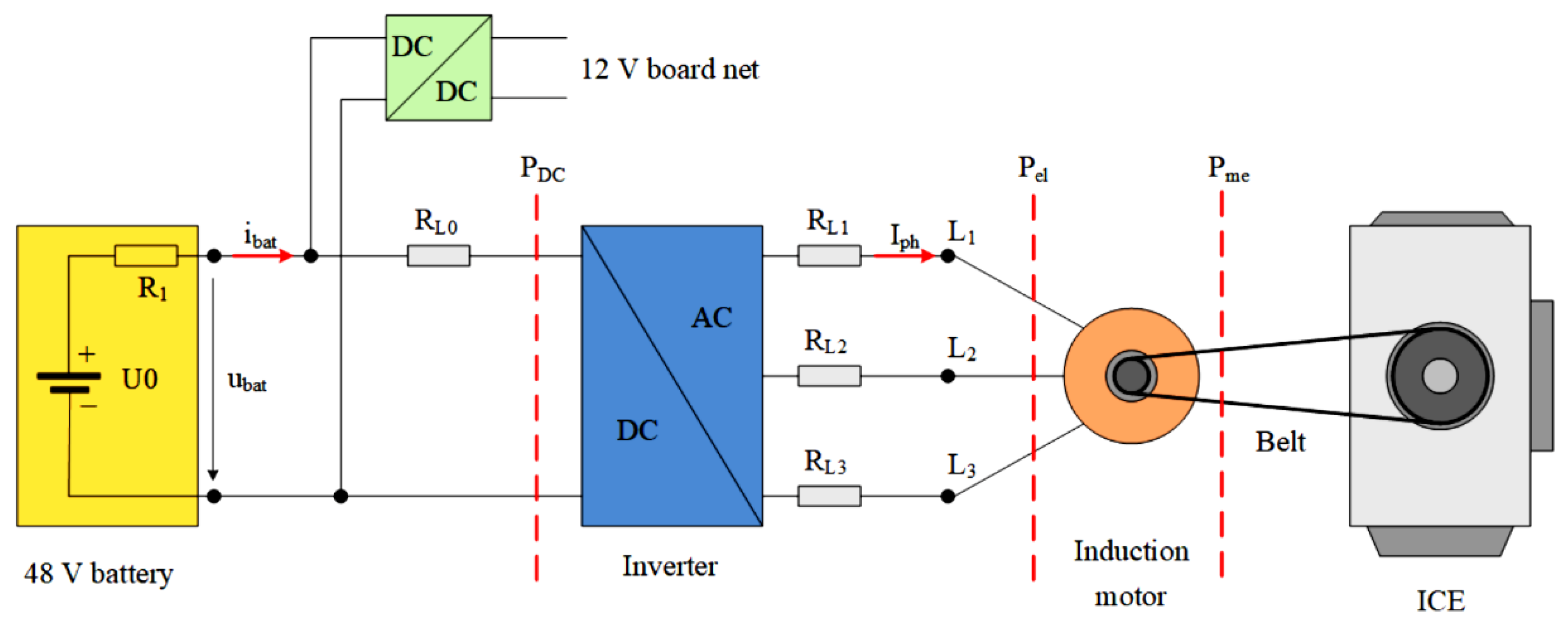
2.1.2. Electrical System Architecture of a 48-V DC Mild Hybrid

Figure 3 shows the principal electrical schematic of the 48-V system considered in this work, utilizing an induction motor connected via belt to the crankshaft pulley in a P0 mild hybrid configuration [10]. The key benefit of a 48-V hybrid system is that it consists of only a few core components: an alternating current (AC) electrical machine of induction (asynchronous) type, an inverter, an energy storage system with high dynamic capability, and a DC/DC converter [45].
The main functions of the induction motor are (1) to convert the kinetic to electrical energy during deceleration phases (energy recuperation), (2) to support the ICE with additional torque (torque boosting or torque filling functionality, Figure 1), and (3) to run the ICE crankshaft up to the speed at which combustion starts during the stop/start operating regimes. Since an induction motor used for a BSG purpose requires a three-phase alternating current power supply, an DC to AC power converter (inverter) is used for that purpose. In order to supply the 12-V electrical consumers with energy from the 48-V DC bus, a unidirectional DC/DC power converter is used to safely transfer energy from the 48-V to the 12-V level. For more details about AC/DC and DC/DC electronic power converter operation, the reader is kindly referred to [46].
Additional components needed to make the system operational are the timing belt and the so-called belt tensioner. The belt has to be designed to meet very high torque requirements and must be kept evenly tensioned by the tensioner, regardless of the power train operating regime or rotation direction [10].

2.1.3. Front End Accessory Drive (FEAD)

The front end accessory drive (FEAD) is an electromechanical system of timing belt-connected pulleys that transfers the power from the crankshaft of the ICE or the rotor of the BSG to auxiliary consumers, such as the air conditioning system and the cooling water pump [10]. Depending upon whether the starter generator is operated for power generation (energy recuperation) or as a motor providing the additional torque to the belt drive, the tight and slack spans alternate and the tensioner function is needed in different sections of the belt [14].
The simplest way to satisfy this requirement is to implement two separate tensioning elements, one positioned before and the other after the pulley of the BSG, as illustrated in Figure 4. This enables the pre-tensioning force to be optimal for the respective timing belt drive operating point [47]. However, by using the timing belt and pulley system, additional compliance (elasticity) is introduced into the FEAD electrical drive system, which may, in turn, produce notable belt longitudinal vibrations under certain operating conditions (i.e., start/stop operation and torque boosting). This may become an issue in the FEAD electrical drive control system design and is addressed in the following sections.

2.2. FEAD Model

This section presents the mathematical model of the FEAD electrical drive, including the induction machine suitable for field-oriented (vector) control and the model of the belt drive used as the mechanical transmission system between the FEAD and the ICE.

2.2.1. Control-Oriented Model of the Servo-Controlled BSG Electrical Machine

It is assumed that the induction machine used in the belt starter/generator electrical servo drive is current/torque controlled by means of an embedded power converter (inverter) equipped with phase current sensors and a field-oriented (vector) control system [48]. Moreover, it is assumed that the embedded current/torque controller is tuned for a well-damped and fast reference step response [49]. In that case, the developed BSG servomachine torque vs. torque reference dynamics can be approximated by a first-order lag term, characterized by unit gain and a small (parasitic) time constant, Tm, which is represented by the following Laplace domain transfer function model:
G m ( s ) = m B S G ( s ) m R ( s ) = 1 T m s + 1 .
For more detailed insight into the alternating current machine control system design and power converter control, the reader is kindly referred to references [35,47,48,49].

2.2.2. Belt Drive Dynamic Model

The relatively complex belt-driven mechanism of the front end accessory drive is modeled as a two-mass spring-damper system. In this approach, the BSG and ICE crankshaft in Figure 4 represent the rotational inertia elements, coupled by a parallel, connected spring-damper system corresponding to the compliance and damping properties of the belt transmission system, as shown in Figure 5. The model is characterized by the ICE and BSG inertias, JICE and JBSG, and their respective radii, rICE and rBSG, whereas the belt transmission is characterized by its longitudinal stiffness, kL, and longitudinal damping, dL.
Equations describing the rotational dynamics of the accessory drive modeled as a two-mass elastic system and belt tension force in Figure 5 are obtained using the D’Alembert principle (cf. [50]), and read as follows:
J B S G d ω B S G d t = m B S G F b e l t r B S G ,
F b e l t = k L ( x B S G x I C E ) + d L ( v B S G v I C E ) ,
J I C E d ω I C E d t = F b e l t r I C E m I C E ,
where ωBSG and ωICE are timing belt angular velocities at BSG and ICE crankshafts and vBSG and vICE are timing belt tangential velocities at BSG and ICE crankshafts, measured relatively to the center of their rotation, while xBSG and xICE are the corresponding belt tangential displacements at BSG and ICE sides, respectively. The tangential displacements (belt elongation xBSGxICE) and tangential speed difference vBSGvICE define the belt tension force, Fbelt, which transfers the torque between the BSG pulley and ICE pulley element.
However, the active damping control system design described in [36,51], which is well suited for electrical drive speed control, considers the torsional form of compliant coupling between the two inertias (in this case, JICE and JBSG); so, the longitudinal model of the belt dynamics needs to be transformed into its rotational equivalent, as shown in Figure 6.
The equivalent rotational dynamics of the belt drive are given by the following set of dynamic equations:
J B S G d ω B S G d t = m B S G m ,
m = k T ( α B S G α I C E ) + d T ( ω B S G ω I C E ) = k T Δ α + d T Δ ω ,
J I C E d ω I C E d t = m m I C E ,
where αBSG and αICE are the angular positions of the BSG and ICE crankshafts, ibelt = rICE/rBSG is the belt drive transmission ratio, Δα and Δω are the angular displacement and speed differences, and m is the equivalent torque of the belt drive rotational model, while the equivalent torsional stiffness and damping factors, kT and dT, are defined as (see, e.g., [51]):
k T k L r I C E 2 ,
d T d L r I C E 2 .
The overall dynamic model may also include friction at the motor side, which can be described by the so-called Stribeck friction characteristic [52]:
m f ( ω B S G ) = [ M C + ( M S M C ) e | ω B S G / ω s | δ ]   sgn ( ω B S G ) ,
where MC is the Coulomb or dry friction torque, MS is the maximum static friction torque (breakaway torque), ωs is the Stribeck speed, and δ is the Stribeck coefficient (δ ∈ [0.5,2]).

2.3. Control System Design

This section presents the results of the FEAD control system design, which is based on the cascade control system structure comprising the inner fast current/torque control system and the superimposed induction machine speed control system. The cascade control system design has been carried out based on the damping optimum criterion.

2.3.1. Damping Optimum Criterion

The feedback controller tuning in this work is based on the damping optimum criterion [34], which is a pole-placement-like method of designing linear continuous-time control systems with a full or reduced-order controller using the following formulation of the closed-loop system characteristic polynomial:
A c ( s ) = D 2 n 1 D 3 n 2 D n T e n s n + + D 2 T e 2 s 2 + T e s + 1 ,
where Te is the closed-loop system equivalent time constant and D2, D3, …, Dn are the so-called characteristic ratios. In the optimal case of Di = 0.5 (i = 2 … n), the closed-loop system of any order n has a quasi-aperiodic step response characterized by an overshoot of approximately 6% (resembling a second-order system with damping ratio ζ = 0.71) and the approximate rise time between 1.8·Te and 2.1·Te.
For larger Te value choices, the dominant closed-loop modes are characterized by a slower response, which generally improves the control system robustness and decreases the noise sensitivity. The response damping can be adjusted through varying the characteristic ratios D2, D3, …, Dn. In particular, the damping of dominant closed-loop modes is determined by the most dominant characteristic ratio D2, with their damping being increased through reducing of the characteristic ratio D2 below the optimal value 0.5, and vice versa.

2.3.2. BSG Electrical Machine Speed Control System

Figure 7 shows the BSG electrical servomachine control system structure in a so-called cascade control system arrangement [35]. In this control setup, the superimposed speed controller commands the torque reference to the current/torque-controlled BSG induction machine, which, in turn, drives the timing belt drive connecting the belt starter generator and the internal combustion engine. As explained above, the BSG servo-drive is characterized by two inertias (i.e., BSG and ICE inertias) connected through the compliant (elastic) belt transmission system, which results in the following characteristic (resonant) frequencies of the electrical servo-drive:
Ω 01 = k T J B S G i b e l t 2 , Ω 02 = k T J I C E , Ω 0 = Ω 01 2 + Ω 02 2 ,
with Ω01 corresponding to the case of “locked” ICE inertia, Ω02 corresponding to stiff BSG-side speed control, and Ω0 being the resonant frequency of the freely oscillating belt drive [29,50].

2.3.3. Active Damping PI Speed Controller Tuning

If the belt transmission compliance is neglected (i.e., stiff transmission assumption), the PI speed controller can be tuned according to the so-called symmetrical optimum [35,50]. This approach results in the following expressions for PI speed controller integral time constant T and the proportional gain K with respect to the BSG and ICE inertias (JBSG and JICE), timing belt drive transmission ratio ibelt, and the equivalent torque lag TΣ (which also includes the speed measurement lag and effects of sampling in the case of a discrete-time controller):
T c ω = 4 T Σ ,
K c ω = J B S G + J I C E / i b e l t 2 2 T Σ .
However, this kind of tuning typically results in pronounced electrical drive vibrations, i.e., oscillations of the load-side (ICE side) speed and transmission torque in the case of compliant transmission, which mandates that an active damping PI controller tuning should be sought instead [50].
In order to tune the PI speed controller with vibrations’ active damping capability using the damping optimum methodology, some realistic assumptions can be made related to the speed control system in Figure 7. Namely, if BSG servomachine friction torque variations are negligible during the drive motion (Δmf = 0, linear drive operating regime) while the equivalent torque lag TΣ is rather small (TΣ << 1/Ω02) [50] and the belt drive equivalent damping coefficient can be regarded as negligible (dT = 0), the following fourth-order transfer function model is obtained between the speed reference ωR and ICE speed referred to the BSG side (Figure 7, see also analysis in [50]):
G c ( s ) = i b e l t ω I C E ( s ) ω R ( s ) = 1 a c 4 s 4 + a c 3 s 3 + a c 2 s 2 + a c 1 s + 1 ,
with the individual transfer function coefficients ac1ac4 defined as:
a c 4 = ( J B S G + J I C E / i 2 ) T c ω K c ω 1 Ω 0 2 ,
a c 3 = T c ω Ω 02 2 ,
a c 2 = ( J B S G + J I C E / i 2 ) T c ω K c ω 1 + Ω 02 2 ,
a c 1 = T c ω .
By equating the above coefficients ac1, ac2, ac3, and ac4 with the coefficients of the fourth-order damping optimum characteristic polynomial according to (11), the following expressions for active damping PI controller tuning are obtained:
T c ω = T e ω = 1 D 2 ω D 3 ω Ω 02 ,
K c ω = T c ω ( J B S G + J I C E / i b e l t 2 ) Ω 02 2 D 2 ω T c ω 2 Ω 02 2 1 .
The above expressions indicate that the PI speed controller is tuned with respect to the resonance frequency Ω02 and the closed-loop system dominant dynamics should be well-damped for the optimal characteristic ratio values (D2ω = D3ω = 0.5). It should be noted, however, that the PI controller having only two tuning parameters (proportional gain K and integral time constant T) is unable to freely tune the damping of high-frequency modes related to the highest-order coefficient ac4 of the closed-loop transfer function denominator. Even though this means that some high-frequency vibration modes may still be observed in the speed control system transient response with the active damping PI controller, the dominant closed-loop control system behavior should still be rather well damped [50].

3. Simulation Results

The BSG drive active damping speed control system was verified by means of comparative simulations, conducted in MATLAB/SimulinkTM software environment, followed by a more through simulation within AVL EXCITETM and AVL CRUISETM M simulation software suites [10].

3.1. MATLAB/Simulink Environment

The MATLAB/Simulink-based simulation represents the first step in the verification of the proposed active damping control of the BSG electrical drive, due to its flexibility and ready connectivity with the more sophisticated AVL EXCITE/CRUISE M simulation software environments. Table 1 lists the parameters of a BSG electrical drive with embedded current torque/control, while the parameters of PI controllers for the case of stiff transmission assumption (symmetrical optimum tuning) and for the case of active damping control of the compliant timing belt drive are listed in Table 2.
Simulation results for the two characteristic cases of PI speed controller tuning in Table 2 are presented in Figure 8. The simulation scenario consists of two characteristic phases encountered during the ICE start-up: (1) the initial engine start-up phase under BSG drive speed control (interval 0 s–0.4 s in Figure 8) and (2) ICE idling at approximately constant throttle and speed with BSG drive speed controller disabled (interval 0.4 s–0.8 s in Figure 8). Figure 8a shows the simulations’ results for the case when the “stiff” PI controller (i.e., one tuned for fast response according to Equations (13) and (14)) is used for BSG drive speed control. The results showed that such controller tuning results in unavoidable excitation of timing belt drive resonant modes, characterized by the resonant frequency of a freely oscillating BSG drive (Ω0 = 133.7 rad/s) during the initial BSG operation at its torque limit and after the start-up is completed, whereas resonant mode characteristic for a freely oscillating load due to stiff BSG speed control (Ω02 = 47.4 rad/s) is present when the BSG torque is not limited (saturated) during the second part of the start-up phase. After the ICE start-up is completed, and ICE starts idling with constant throttle (torque) and timing belt drive oscillations with relatively high magnitudes persist due to relatively low damping of the timing belt (Table 1). The results in Figure 8b show that timing belt vibrations can be effectively suppressed during the initial ICE start-up phase by using the active damping PI controller. After the speed control is turned off following the end of start-up phase, the relatively small-magnitude speed and belt force vibrations do occur, which are much less emphasized compared to the case when the “stiff” PI controller was used in Figure 8a. Namely, the active damping PI controller does not excite these vibration modes in the first place, so their effect is much less emphasized once the BSG speed-controlled start-up is finished, thus resulting in three to five times smaller magnitudes of residual belt drive oscillations after the engine start-up phase (cf. BSG torque traces in Figure 8a,b).

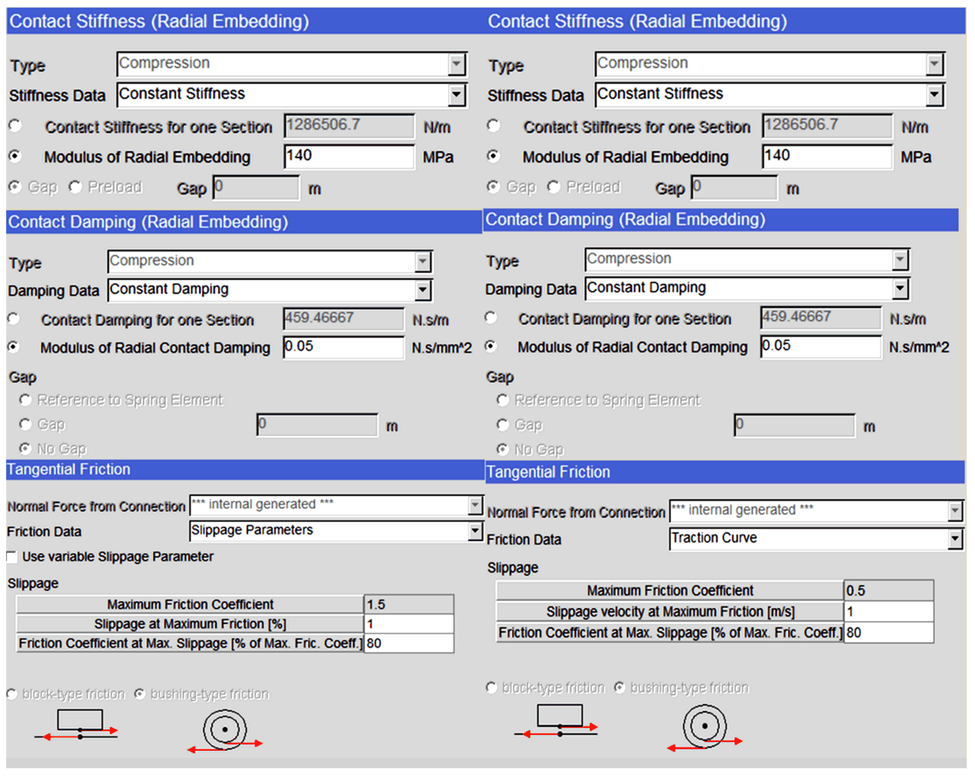
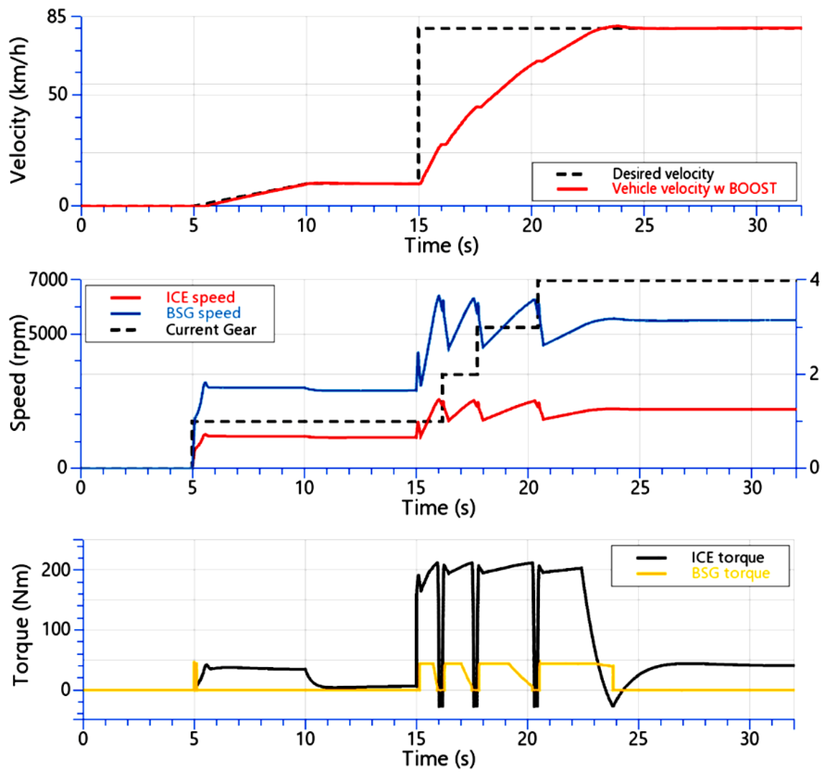
3.2. AVL EXCITE/CRUISE M Environment

AVL EXCITETM (version 2020) developed by AVL List GmbH (Graz, Austria) is a multi-body dynamics software for power-train analysis, which reduces the need for prototyping, which is characterized by high computational efficiency. Timing Drive module within AVL EXCITETM is used to model the FEAD and to couple it with the speed-controlled BSG drive model from MATLAB/SimulinkTM release R2019b (with the latter developed by MathWorks, Natick, MA, USA) in order to perform a co-simulation for the purpose of obtaining more realistic results compared to the simplified simulation model in Figure 7. The connection between the MATLAB/SimulinkTM and EXCITE TM software environments is made by using a so-called S-function block within Simulink, serving as an interface between these two software environments, wherein EXCITE TM controls the time step size and the convergence of the simulation. Figure 9 shows the principal schematic of MATLAB/SimulinkTM co-simulation with EXCITETM, along with the FEAD multi-body model [10].
FEAD model is implemented and coupled to the MATLAB/Simulink BSG model by using The Timing Drive module, which is a dedicated module specialized for the analysis of belt-driven systems within EXCITE capable of capturing many more physical phenomena compared to the dynamics of the two-mass elastic FEAD approximation, such as the belt vs. pulley slippage. The accessory drive is modeled using the Non Toothed Belt macro element within EXCITE, corresponding to the particular FEAD configuration shown in Figure 9. FEAD model parameters and configuration settings within the EXCITE model are given in Figure 10, with the compliance (stiffness) and damping properties of the elastic belt multi-segment model shown in Figure 11. For the particular simulation study, the elastic belt is modeled by 150 discrete elastic segments [10].
AVL CRUISETM M (version 2020 also developed by AVL List GmbH, Graz, Austria) is a multi-disciplinary vehicle system simulation tool that can be used for power train concept analysis, sub-system design, and virtual component integration, as well as control function development on the HIL (Hardware-in-the-Loop) and test-bed environments. AVL CRUISETM M system simulation environment was used herein to integrate the speed-controlled BSG drive model from Simulink, compiled as the so-called Functional Mock-up Unit (FMU), into a model of a P0 hybrid vehicle power train, as shown in Figure 12a [10]. This power train sub-model was a part of the larger overall model of the road vehicle, illustrated in Figure 12b, which was also equipped with an appropriate vehicle driver model (see, e.g., [53]) and mechanical transmission gear shifting logic.
A suitable engine starting scenario followed by a vehicle launch was generated within AVL CRUISE M for the purpose of testing the start/stop and torque boosting functions of the considered P0 hybrid vehicle. These vehicle operating regimes were represented by the desired vehicle velocity profile, which serves as the speed reference (target value) for the driver model. The particular driving regime was designed to emphasize the response of the BSG in the boosting mode of operation by using an abrupt change of the vehicle velocity target, which will provoke the control system to request the maximum torque output from the BSG in order to accelerate the vehicle [10]. The stop/start and torque boost control logic flowchart corresponding to the aforementioned vehicle driving regime is shown in Figure 13, wherein it determines the statuses (logic states) for key power train variables defining the power train start-up and vehicle launch operating regimes [10].
Figure 14 shows the BSG and ICE speed responses, and the BSG torque generated by MATLAB/Simulink model and exchanged via the S-function interface with the EXCITE FEAD model [10], as well as the torque transferred to the ICE crankshaft. It is apparent that there existed a notable difference between ICE crankshaft speed profiles of the simplified MATLAB/Simulink model (Figure 8b) and the more comprehensive result obtained by using the ECXITE FEAD model co-simulation with the MATLAB/Simulink-based PI speed control system (Figure 9, Figure 10 and Figure 11). The main reason for the discrepancy between these results was the timing belt tangential slippage, which lowered the torque transferred from the BSG side to the ICE crankshaft according to Equation (6). This consequently resulted in lower acceleration of the ICE crankshaft according to Equation (7). In actual implementation, the EXCITE-based FEAD simulation model used the timing belt mass-spring-damper model comprising 150 finite elements, whose contact with BSG and ICE pulleys is characterized by belt vs. pulley friction modeled within the EXCITE programming suite such that realistic simulation of belt slippage observed in an actual engine can be reproduced [10].
Figure 15 shows the tangential slippage profiles of five equidistant belt mass elements (numbered 30, 60, 90, 120, and 150) as they come into contact with the ICE crankshaft pulley. The results showed that the slippage tended to be larger at the beginning of the co-simulation, which was when the BSG drive started accelerating (slippage higher than 35% is observed in that case), which was due to the tensioner not being able to keep the belt tightened when such high-speed changes of the BSG pulling torque and BSG acceleration were applied. As the co-simulation progressed, and the applied BSG torque and angular speed entered a quasi-steady state, the slippage tended to decrease, as would be expected in the realistic BSG electrical drive.
The above results of the MATLAB/Simulink co-simulation with the EXCITE-based FEAD model showed that the active damping tuning or the BSG electrical drive PI speed controller also resulted in favorable behavior of the overall FEAD system characterized by the realistic timing belt slippage effects, i.e., it did not excite timing belt vibrations due to belt compliance effects. This means that the active damping controller can be used for the more comprehensive simulation study of the overall vehicle driveline system and testing of the FEAD torque boosting capability within the CRUISETM M software environment.
For the purpose of testing the start/stop and torque boosting functions of the P0 hybrid vehicle within the CRUISETM M software environment, a step change of the desired vehicle velocity (a vehicle launch scenario) was used to provoke the control system to request the maximum torque output from the BSG after the engine start-up in order to help accelerate the vehicle. Simulations results for this driving scenario are shown in Figure 16 and Figure 17.
Figure 16 shows the vehicle velocity, BSG and ICE angular speed, and torque responses within the time frame during which the engine start-up occurred, which was immediately followed by the vehicle launch sequence characterized by successive gears shifting from idle (gear = 0) to fourth gear (gear = 4). Responses in Figure 16 show that the stop/start functionality of the BSG was working properly since the ICE started developing its torque after it was run up to an angular speed of 750 rpm. This corresponded to the ICE switch-on point (middle plot in Figure 16), wherein the transmission was engaged in the first gear and the vehicle slowly accelerated to 10 km/h (time interval from 5 s to 15 s). The boosting operating mode of the BSG depended on the request from the driver, which, in this case, consisted of fully engaged gas pedal intervals, interspersed with low acceleration demands (idle gas pedal) during transmission shifting from the first to the fourth gear (cf. traces in the middle and bottom plot in Figure 16). This sequence of commands was due to the action of the vehicle driver model aimed at achieving zero velocity tracking error, as discussed in [5], which, in turn, tried to reach the fixed vehicle velocity target of 80 km/h in the minimum time by commanding the maximum driveline torque (see top plot in Figure 16). In order to fulfill this task, the BSG drive performed torque boosting with the maximum available torque (characterized by its torque limit value of 75 Nm) throughout the vehicle acceleration process, i.e., from 10 km/h to 80 km/h, finally reaching the desired vehicle velocity within 8 s (time frame between 15 s and 23 s).
Figure 17 shows that the vehicle accelerated faster when the boosting function was enabled, that is, when both the BSG and ICE provided the power train torque (red traces in Figure 17), as opposed to the case when the ICE was accelerating the vehicle by itself (green traces in Figure 17). The comparison was made with the gear shifting point being set at 2500 rpm, which was a suboptimal gear shifting point for the ICE but was chosen as a practical trade-off related to the rated speed of the BSG electrical machine. Nevertheless, for this particular gear shifting regime, about 30% acceleration gain was obtained during the vehicle launch phase. In order to obtain a more faithful comparison, the ICE was also operated alone with the gear shifting point set to 4425 rpm (blue traces in Figure 17), which represented the ICE maximum torque operating point in the model. This case was characterized by a slightly better acceleration performance, i.e., about 10% greater acceleration was obtained compared to the case of torque boosting with gear shifting at 2500 rpm. However, in this case, the beneficial effect of the BSG-based torque boosting and the related fuel savings due to the battery-based power boost could not be utilized due to BSG speed constraints [54].

4. Conclusions

The paper presented the design of a speed control system with active damping of timing belt vibrations for an induction machine-based belt starter generator (BSG) drive of a mild hybrid vehicle in a P0 configuration using a common 48-V DC bus. The control system design was based on the damping optimum criterion, yielding analytical relationships between the process model and controller parameters for the desired closed-loop system damping.
The performance of the presented BSG drive control system as a part of the frontend accessory drive (FEAD) was initially tested within the MATLAB/SimulinkTM environment using a simplified two-mass elastic model representation of the FEAD system. This was followed by a more thorough verification using a comprehensive multi-body model of the FEAD system within AVL EXCITE TM and finally using a macro level simulation of the overall vehicle dynamics in AVL CRUISETM M featuring the proposed BSG control system as an integral part of the P0 mild hybrid power train of the road vehicle.
Simulation results showed that the proposed BSG drive speed control system with an active damping PI controller tuned according to damping optimum and implemented within the MATLAB/SimulinkTM is indeed capable of mitigating the timing belt drive vibrations. In particular, the vibration magnitude during engine start-up was reduced between three and five times compared to the case of default PI speed controller tuning. Moreover, the more comprehensive multi-body model of the FEAD in AVL EXCITETM is capable of reproducing the timing belt slippage effects, while also showing the effectiveness of the active damping PI controller in terms of belt vibrations’ mitigation.
Finally, the proposed BSG drive speed control system was successfully integrated within the AVL CRUISETM M simulation environment and was used to simulate the ICE start/stop functionality and torque boosting performance for the particular launching (acceleration) scenario of the vehicle equipped with the P0 mild hybrid power train. The results of such more-comprehensive simulations confirmed that the proposed active damping BSG speed controller can be integrated within the control system of a mild hybrid power train and facilitates a favorable torque boosting performance during vehicle launch, resulting in 30% gain in acceleration compared to the case without torque boosting when gear shifting was performed at ICE speed of 2500 rpm. This was only slightly less effective (10% slower) compared to the “optimal” vehicle acceleration result achieved with gear shifting at 4425 rpm engine speed, which, in turn, cannot fully utilize the benefits of the FEAD-based torque boosting.
Future work on P0 hybrid power train speed/torque control may be directed towards (1) implementation of the proposed active damping control system on the embedded microcontroller hardware, (2) control system testing on a virtual test bed, and (3) hardware-in-the-loop (HIL) simulation tests.

Author Contributions

Conceptualization, F.P., D.P. and M.C.; methodology, F.P., D.P., M.K., M.C. and J.K.; software, F.P. and M.C.; validation, D.P. and M.K.; formal analysis, D.P. and F.P.; investigation, F.P., D.P., M.C. and M.K.; resources, M.C.; writing—original draft preparation, D.P. and F.P.; writing—review and editing, M.K., D.P., J.K. and M.C.; visualization, D.P. and M.C.; supervision, D.P.; project administration, M.C.; funding acquisition, M.C. All authors have read and agreed to the published version of the manuscript.

Funding

It is gratefully acknowledged that this research was funded by the EU European Regional Development Fund under the Grant number KK.01.1.1.04.0010 (HiSkid: Development of Hybrid Skidder).

Institutional Review Board Statement

Not applicable.

Informed Consent Statement

Not applicable.

Data Availability Statement

Data sharing not applicable.

Acknowledgments

This research was supported by AVL AST Zagreb, Croatia, and the European Regional Development Fund through grant Nos. KK.01.1.1.01.0009 (DATACROSS: Advanced Methods and Technologies in Data Science and Cooperative Systems) and KK.01.1.1.04.0010 (HiSkid: Development of Hybrid Skidder).

Conflicts of Interest

The authors declare no conflict of interest. The funding body had no role in the design of the study; in the collection, analyses, or interpretation of data; in the writing of the manuscript; or in the decision to publish the results.

Nomenclature

Abbreviations
ACAlternating current
AVLAnstalt für Verbrenneungskraftmachinen List (company name)
BSGBelt starter generator
CO2Carbon dioxide
DCDirect current
FEADFront end accessory drive
FMUFunctional Mock-up Unit (model within AVL CRUISETM M software)
GHGGreenhouse gases
HILHardware-in-the-Loop
ICEInternal combustion engine
HEVHybrid electric vehicle
FHEVFull hybrid electric vehicle
MHEVMild hybrid electric vehicle
PHEVPlug-in hybrid electric vehicle
PIProportional-integral (controller)
Variables
FbeltTiming belt transmitted force [N]
mEquivalent torque of the belt-drive rotational model [N⋅m]
mBSG, mRBSG servomachine developed torque and reference value [N⋅m]e
mfFriction torque [N⋅m]
vBSG, vICETiming belt tangential velocities at BSG and ICE crankshafts [m/s]
xBSG, xICETiming belt tangential displacements at BSG and ICE crankshafts [m]
αBSG, αICETiming belt angular displacement at BSG and ICE crankshafts [rad]
ΔαTwo-mass elastic model angular displacement [rad]
ΔωTwo-mass elastic model angular velocity (speed) difference [rad/s]
ωR, ωBSGBSG reference speed and actual angular velocity [rad/s]
ωICEICE angular velocity [rad/s]
Parameters
D2, …, DnDamping optimum characteristic ratios (dimensionless)
D2ω, D3ωActive damping controller design characteristic ratios (dimensionless)
ibeltBelt drive transmission ratio (dimensionless)
JBSG, JICEBSG and ICE moments of inertia [kg⋅m2]
kLTiming belt equivalent longitudinal stiffness [N/m]
kTBelt drive equivalent torsional stiffness [N⋅m/rad]
dLTiming belt equivalent longitudinal damping factor [N⋅s/m]
dTBelt drive equivalent torsional damping factor [N⋅m⋅s/rad]
KPI controller proportional gain (dimensionless)
TPI controller integral time constant [s]
MmaxServomachine torque limit value [N⋅m]
MC, MSCoulomb and static friction torque [N⋅m]
rBSG, rICETiming belt drive crankshaft radii at BSG and ICE side [m]
Te, TEquivalent time constant: general case and speed control loop [s]
TmCurrent/torque closed-loop system equivalent time constant [s]
TΣEquivalent overall torque lag in speed control system design [s]
δStribeck coefficient (dimensionless)
ωsStribeck speed [rad/s]
Ω0, Ω01, Ω02Timing belt drive resonant frequencies [rad/s]

References

  1. Saber, A.Y.; Venayagamoorthy, G.K. Plug-in Vehicles and Renewable Energy Sources for Cost and Emission Reductions. IEEE Trans. Ind. Electron. 2011, 58, 1229–1238. [Google Scholar] [CrossRef]
  2. Hansen, J.; Sato, M.; Kharecha, P.; Beerling, D.; Berner, R.; Masson-Delmotte, V.; Pagani, M.; Raymo, M.; Royer, D.L.; Zachos, J. Target atmospheric CO2: Where should humanity aim? Open Atmos. Sci. J. 2008, 2, 217–231. [Google Scholar] [CrossRef] [Green Version]
  3. Deur, J.; Škugor, B.; Cipek, M. Integration of Electric Vehicles into Energy and Transport Systems. Automatika 2015, 56, 395–410. [Google Scholar] [CrossRef] [Green Version]
  4. European Commission. Reducing CO2 Emissions from Passenger Cars—Before 2020. Available online: https://ec.europa.eu/clima/policies/transport/vehicles/cars_en (accessed on 15 January 2021).
  5. Pavković, D.; Cipek, M.; Kljaić, Z.; Mlinarić, T.J.; Hrgetić, M.; Zorc, D. Damping Optimum-Based Design of Control Strategy Suitable for Battery/Ultracapacitor Electric Vehicles. Energies 2018, 11, 2854. [Google Scholar] [CrossRef] [Green Version]
  6. Bethoux, O. Hydrogen Fuel Cell Road Vehicles: State of the Art and Perspectives. Energies 2020, 13, 5843. [Google Scholar] [CrossRef]
  7. US Department of Energy. Hybrid and Plug-In Electric Vehicles; DOE/GO-102014-4350. Available online: https://cleancities.energy.gov (accessed on 15 January 2021).
  8. Xue, Q.; Zhang, X.; Teng, T.; Zhang, J.; Feng, Z.; Lv, Q. A Comprehensive Review on Classification, Energy Management Strategy, and Control Algorithm for Hybrid Electric Vehicles. Energies 2020, 13, 5355. [Google Scholar] [CrossRef]
  9. Tran, D.D.; Vafaeipour, M.; El Baghdadi, M.; Barrero, R.; Van Mierlo, J.; Hegazy, O. Thorough state-of-the-art analysis of electric and hybrid vehicle powertrains: Topologies and integrated energy management strategies. Renew. Sustain. Energy Rev. 2020, 119, 109596. [Google Scholar] [CrossRef]
  10. Plavac, F. Modelling and Control of Hybrid Propulsion Systems for Multirotor Unmanned Aerial Vehicles. Master’s Thesis, Faculty of Mechanical Engineering and Naval Architecture, University of Zagreb, Zagreb, Croatia, 2020; 135p. [Google Scholar]
  11. Yong, J.Y.; Ramachandramurty, V.K.; Tan, K.M.; Mithulananthan, N. A review of the state-of-the-art technologies of electric vehicle, its impacts and prospects. Renew. Sustain. Energy Rev. 2015, 49, 365–385. [Google Scholar] [CrossRef]
  12. Ito, Y.; Tomura, S.; Moriya, K. Vibration-Reducing Motor Control for Hybrid Vehicles; R&D Review of Toyota CRDL; Toyota Central R&D Labs: Nagakute, Japan, 2005; Volume 40, pp. 37–43. [Google Scholar]
  13. Hwang, H.-Y.; Lan, T.-S.; Chen, J.-S. Control Strategy Development of Driveline Vibration Reduction for Power-Split Hybrid Vehicles. Appl. Sci. 2020, 10, 1712. [Google Scholar] [CrossRef] [Green Version]
  14. Cardoso, D.S.; Fael, P.O.; Espírito-Santo, A. A review of micro and mild hybrid systems. Energy Rep. 2020, 6, 385–390. [Google Scholar] [CrossRef]
  15. Nazari, S.; Siegel, J.; Middleton, R.; Stefanopoulou, A. Power Split Supercharging: A Mild Hybrid Approach to Boost Fuel Economy. Energies 2020, 13, 6580. [Google Scholar] [CrossRef]
  16. Scamarcio, A.; Gruber, P.; De Pinto, S.; Sorniotti, A. Anti-jerk controllers for automotive applications: A review. Annu. Rev. Control 2020, 50, 174–189. [Google Scholar] [CrossRef]
  17. Chen, J.-S. Vibration reduction in electric bus during acceleration and gear shifting. Adv. Mech. Eng. 2015, 7, 1–16. [Google Scholar] [CrossRef] [Green Version]
  18. Cipek, M.; Pavković, D.; Petrić, J. A control-oriented simulation model of a power-split hybrid electric vehicle. Appl. Energy 2013, 101, 121–133. [Google Scholar] [CrossRef]
  19. Bu, F.; Liu, H.; Huang, W.; Hu, Y.; Degano, M.; Gerada, C.; Rajashekara, K. Induction-Machine–Based Starter/Generator Systems: Techniques, Developments, and Advances. IEEE Ind. Electron. Mag. 2020, 14, 4–19. [Google Scholar] [CrossRef]
  20. Jurca, F.-N.; Ruba, M. Performance Analysis of an Integrated Starter-Alternator-Booster for Hybrid Electric Vehicles—Chapter 5. In Hybrid Electric Vehicles; IntechOpen: London, UK, 2017; pp. 105–124. [Google Scholar] [CrossRef] [Green Version]
  21. Jeon, S.; Lee, G.S.; Kang, D.-W.; Kim, W.-H.; Bae, S. Belt-Driven Integrated Starter and Generator Using Planetary Gears for Micro Hybrid Electric Vehicles. IEEE Access 2021, 9, 56201–56213. [Google Scholar] [CrossRef]
  22. Ossareh, H.R.; Wisotzki, S.; Buckland Seeds, J.; Jankovic, M. An Internal Model Control-Based Approach for Characterization and Controller Tuning of Turbocharged Gasoline Engines. IEEE Trans. Control Syst. Technol. 2021, 29, 866–875. [Google Scholar] [CrossRef]
  23. Atzler, F.; Wegerer, M.; Mehne, F.; Rohrer, S.; Rathgeber, C.; Fischer, S. Fuel Consumption and Emissions Effects in Passenger Car Diesel Engines through the Use of a Belt Starter Generator; SAE Technical Paper 2015-01-1162; SAE International: Warrendale, PA, USA, 2015. [Google Scholar] [CrossRef]
  24. Lee, H.; Lee, K. Comparative Evaluation of the Effect of Vehicle Parameters on Fuel Consumption under NEDC and WLTP. Energies 2020, 13, 4245. [Google Scholar] [CrossRef]
  25. Millo, F.; Accurso, F.; Zanelli, A.; Rolando, L. Numerical Investigation of 48 V Electrification Potential in Terms of Fuel Economy and Vehicle Performance for a Lambda-1 Gasoline Passenger Car. Energies 2019, 12, 2998. [Google Scholar] [CrossRef] [Green Version]
  26. Dwars, S. Recent Advances in Soft Torque Rotary Systems. In Proceedings of the 3rd International Colloquium on Nonlinear Dynamics and Control of Deep Drilling Systems, Minneapolis, MN, USA, 29–30 May 2014; pp. 29–44. [Google Scholar]
  27. Fossati, G.G.; Fadel Miguel, L.F.; Paucar Casas, W.J. Multi-objective optimization of the suspension system parameters of a full vehicle model. Optim. Eng. 2019, 20, 151–177. [Google Scholar] [CrossRef]
  28. Fadel Miguel, L.F.; Fadel Miguel, L.F.; Holdorf Lopez, R. A firefly algorithm for the design of force and placement of friction dampers for control of man-induced vibrations in footbridges. Optim. Eng. 2015, 16, 633–661. [Google Scholar] [CrossRef]
  29. Jansen, J.D.; van den Steen, L. Active Damping of Self-Excited Torsional Vibrations in Oil Well Drill-strings. J. Sound Vib. 1995, 179, 647–668. [Google Scholar] [CrossRef]
  30. Batzies, E.; Katthän, L.; Welker, V.; Zirn, O. Commissioning rules for optimal velocity controller damping of servo axes using elimination methods. Optim. Eng. 2015, 16, 183–201. [Google Scholar] [CrossRef]
  31. Feng, X.; Shangguan, W.-B.; Deng, J.; Jing, X. Modeling and dynamic analysis of accessory drive systems with integrated starter generator for micro-hybrid vehicles. Proc. Inst. Mech. Eng. Part D J. Automob. Eng. 2019, 233, 1162–1177. [Google Scholar] [CrossRef]
  32. Hsieh, F.-C.; Huang, Y.-D.; Peng, Y.-W. Improving the Stability and Fuel Economy for Belt-Starter Generator Mild HEV at Idle Speed Using Model Predict Control. In Proceedings of the 2014 IEEE International Conference on Automation Science and Engineering (CASE), Taipei, Taiwan, 18–22 August 2014; pp. 916–921. [Google Scholar]
  33. Guan, J.-C.; Chen, B.-C.; Huang, Y.-D.; Chiu, Y.-J. Adaptive Power Management Strategy for Hybrid Electric Vehicle with Belt-driven Starter Generator. In Proceedings of the 2015 IEEE 12th International Conference on Networking, Sensing and Control, Taipei, Taiwan, 9–11 April 2015; pp. 503–508. [Google Scholar]
  34. Naslin, P. Essentials of Optimal Control; Illife Books: London, UK, 1968. [Google Scholar]
  35. Schröder, D. Elektrische Antriebe—Regelung von Antriebssystemen; Springer: Berlin/Heidelberg, Germany, 2007; pp. 814–865. [Google Scholar]
  36. Pavković, D.; Šprljan, P.; Cipek, M.; Krznar, M. Cross-axis control system design for borehole drilling based on damping optimum criterion and utilization of proportional-integral controllers. Optim. Eng. 2021, 22, 51–81. [Google Scholar] [CrossRef]
  37. Matlab Software. Available online: https://www.mathworks.com (accessed on 20 April 2021).
  38. AVL Software. Available online: https://www.avl.com (accessed on 20 April 2021).
  39. Els, P. What Electric Vehicle and Electrification Strategies Are Available to Manufacturers. Available online: https://www.automotive-iq.com/electrics-electronics/articles/automotive-iq-guides-electric-vehicles (accessed on 5 March 2020).
  40. Schöffmann, W.; Sorger, H.; Ennemosser, A.; Priestner, C.; Hütter, M.; Klarin, B. The impact of 48V to friction and efficiency optimization of the base engine—Approach for quantification in future driving cycles. In Reibungsminimierung im Antriebsstrang 2016; Springer Vieweg: Wiesbaden, Germany, 2 November 2017. [Google Scholar]
  41. Continental, A.G. Low Voltage, High Performance: Full-Hybrid Vehicle with 48-Volt High-Power Technology. Available online: https://www.continental.com (accessed on 20 April 2021).
  42. Liao, Y.-J.G.; Quail, A.M., Jr. Experiment and Simulation of Medium-Duty Tactical Truck for Fuel Economy Improvement. Energies 2011, 4, 276–293. [Google Scholar] [CrossRef] [Green Version]
  43. Esser, A.; Eichenlaub, T.; Schleiffer, J.-E.; Jardin, P.; Rinderknecht, S. Comparative evaluation of powertrain concepts through an eco-impact optimization framework with real driving data. Optim. Eng. 2021, 22, 1001–1029. [Google Scholar] [CrossRef]
  44. Azad, N.L.; Mozaffari, A.; Vajedi, M.; Masoudi, Y. Chaos oscillator differential search combined with Pontryagin’s minimum principle for simultaneous power management and component sizing of PHEVs. Optim. Eng. 2016, 17, 727–760. [Google Scholar] [CrossRef]
  45. Klein, B.; Maiwald, O. 48 Volt Technology for More Efficiency and Fun to Drive; Die Bibliothek der Technik, SZ Scala GmbH: Berlin, Germany, 2016; Volume 388, p. 74. [Google Scholar]
  46. Williams, B.W. Power Electronics: Devices, Drivers, Applications and Passive Components; McGraw-Hill: New York, NY, USA, 1992. [Google Scholar]
  47. Schröder., C.; Stuffer, A. P0 Mild Hybrid with System Competence to Maximum Efficiency. In Proceedings of the Schaeffler Symposium 2018—Mobility for Tomorrow, Baden-Baden, Germany, 11–13 April 2018. [Google Scholar]
  48. Novotny, D.W.; Lipo, T.A. Vector Control and Dynamics of AC Drives; Oxford University Press: Oxford, UK, 1996. [Google Scholar]
  49. Rodriguez, J.; Cortes, P. Predictive Control of Power Converters and Electrical Drives; John Wiley & Sons: Chichester, UK, 2012. [Google Scholar]
  50. Dresig, H.; Holzweißig, F. Dynamics of Machinery—Theory and Applications; Springer: Berlin/Heidelberg, Germany, 2010; ISBN 9783540899396. [Google Scholar] [CrossRef]
  51. Pavković, D.; Deur, J.; Lisac, A. A torque estimator-based control strategy for oil-well drill-string torsional vibrations active damping including an auto-tuning algorithm. Control Eng. Pract. 2011, 19, 836–850. [Google Scholar] [CrossRef]
  52. Armstrong-Hélouvry, B.; Dupont, P.; Canudas-de-Wit, C. A Survey of Models, Analysis Tools and Compensation Methods for the Control of Machines with Friction. Automatica 1994, 30, 1083–1138. [Google Scholar] [CrossRef]
  53. Kiencke, U.; Nielsen, L. Automotive Control Systems; Springer: Berlin/Heidelberg, Germany, 2000. [Google Scholar]
  54. Si, Y.; Liu, Y.; Liu, C.; Zhang, Z.; Wang, M.; Lei, Q. A High Current High Power Density Motor Drive for a 48-Volt Belt-Driven Starter Generator (BSG) System. IEEE Open J. Ind. Appl. 2021, 2, 235–250. [Google Scholar] [CrossRef]
Figure 1. Illustration of internal combustion engine operating point shifting and offsetting [10].
Energies 15 01311 g001
Figure 2. Hybrid vehicle power flow in recuperation mode [10].
Energies 15 01311 g002
Figure 3. A 48-V DC electrical architecture in P0 configuration [10].
Energies 15 01311 g003
Figure 4. Principal schematic of timing belt operation.
Energies 15 01311 g004
Figure 5. Multi-mass model and two-mass elastic model approximation of FEAD [10].
Energies 15 01311 g005
Figure 6. FEAD model with belt drive longitudinal dynamics and its corresponding rotational equivalent [10].
Energies 15 01311 g006
Figure 7. Block diagram of electrical servomachine speed control system with fast inner current/torque control loop embedded within the frequency converter.
Energies 15 01311 g007
Figure 8. Comparative simulations’ results of ICE start-up via BSG drive followed by ICE idling: PI controller with “stiff” tuning (a) and active damping PI controller (b).
Energies 15 01311 g008
Figure 9. Principal scheme of EXCITETM with MATLAB/SimulinkTM co-simulation model with FEAD multi-body model in EXCITETM [10].
Energies 15 01311 g009
Figure 10. FEAD multi-body model parameters including global data, drive layout, rotational elements’ properties, belt geometry, and its mass and elasticity properties [10].
Energies 15 01311 g010
Figure 11. Stiffness, damping, and tangential friction between the belt and the pulley front and back side contacts [10].
Energies 15 01311 g011
Figure 12. Principal scheme of CRUISETM M integration of BSG drive FMU model within P0 mild hybrid power train model (a), and overall road vehicle model (b) [10].
Energies 15 01311 g012
Figure 13. Stop/start and torque boost control logic flowchart [10].
Energies 15 01311 g013
Figure 14. Results of MATLAB/SimulinkTM co-simulation with the FEAD EXCITETM model [10].
Energies 15 01311 g014
Figure 15. Illustration of belt mass element tangential slippage at ICE crankshaft side [10].
Energies 15 01311 g015
Figure 16. CRUISETM M simulation results for ICE start-up followed by vehicle launch [10].
Energies 15 01311 g016
Figure 17. Comparative CRUISETM M simulation results without BSG-based torque boosting and with BSG-based torque boosting included [10].
Energies 15 01311 g017
Table 1. Servo-controlled timing belt drive model parameters.
Parameter DescriptionValue
BSG moment of inertia JBSG0.003 kg m2
ICE moment of inertia JICE0.12 kg m2
Timing belt drive crankshaft radius at BSG side rBSG0.0316 m
Timing belt drive crankshaft radius at ICE side rICE0.0753 m
Timing belt equivalent longitudinal stiffness kL47,520 N/m
Timing belt equivalent longitudinal damping factor dL10 Ns/m
Belt drive equivalent torsional stiffness kT269.4 Nm/rad
Belt drive equivalent torsional damping factor dL0.057 Nms/rad
Belt drive transmission ratio ibelt2.383
Torque closed-loop system equivalent time constant Tm0.16 ms
Equivalent overall lag in speed control system design T0.2 ms
Coulomb friction torque MC9 Nm
Static friction torque MS12 Nm
Stribeck coefficient δ1.0
Stribeck speed ωs0.01 rad/s
Table 2. BSG speed PI controller parameters for stiff and compliant transmission.
Parameter DescriptionValue
Symmetrical optimum (stiff) tuning of PI controllerPI controller proportional gain K11.92
PI controller integral time constant T4 ms
Active damping tuning of PI controllerPI controller proportional gain K1.07
PI controller integral time constant T60 ms
Publisher’s Note: MDPI stays neutral with regard to jurisdictional claims in published maps and institutional affiliations.

