Article

Application of Gas Dissolved in Fuel in the Aspect of a Hypocycloidal Pump Design

Institute of Combustion Engines and Powertrains, Poznan University of Technology, 61-138 Poznan, Poland
*
Author to whom correspondence should be addressed.
Energies 2022, 15(23), 9163; https://doi.org/10.3390/en15239163
Submission received: 30 October 2022 / Revised: 25 November 2022 / Accepted: 28 November 2022 / Published: 2 December 2022

Abstract

:
The advancement of modern injection systems of diesel engines is related to a constant increase in the injection pressures generated by injection pumps. This translates into an improvement of the engine operation indexes, including the emission-related ones. Such an approach brings a series of problems related to the design, construction and durability of the injection system. Therefore, the authors asked whether the current market trend in injection systems is the only appropriate path to be taken. When searching for the answer, the authors decided to propose an innovative concept consisting of dissolving exhaust gas in diesel fuel with the use of an injection pump. Such a saturated solution, when flowing out of the injection nozzle, begins the process of releasing the gas dissolved in the fuel. This has a positive impact on the atomization process, hence the process of combustion. The aim of this paper stems from the previously performed research. Due to the nature of the phenomenon, it was necessary to propose a new design for the injection pump. For correct selection of the dimensions of the pumping section, it was of key importance to determine the coefficient of solubility and the bulk modulus of the solution of diesel fuel and exhaust gas. Aside from the description of the applied method and the results of the direct measurements, this paper presents the yet undescribed results of the measurements of the coefficient of solubility of different concentrations of exhaust gas in diesel fuel. The authors also investigated the influence of the amount of exhaust gas dissolved in the fuel on the bulk modulus of the solution. The final part of the paper is a description of a proprietary design of a hypocycloidal injection pump. The application of the innovative drive allows a correct dissolution of exhaust gas in the fuel.

1. Introduction

Air pollution is currently a serious problem. Depending on the region of the world, it is assumed that the main sources of pollution are household energy (about 52%), industry (about 17%) and road transport (about 10%) [1]. These problems are visible on a daily basis, especially in the pollution of large cities [2,3]. This has a huge and negative impact on human and animal health. Although internal combustion engines are not the main source of pollution, one of the greatest disadvantages faced by their designers is the excessive emission of harmful compounds in exhaust gases [4,5]. In particular, a significant problem is the emission of particulate matter [6,7,8]. Particulate matter with diameters of less than one micron (ultrafine particles) is believed to be the most dangerous to humans. The source of these particles is combustion processes [9]. Activities aimed at reducing the negative impact of this type of machinery on the environment are dictated by more and more stringent emission standards. This problem is solved in many aspects, e.g., by optimization of the combustion process, by the use of exhaust gas aftertreatment systems or alternative fuels, by significant design modifications, or generally speaking, by developing internal combustion engines, all of which result from the broadly understood progress of knowledge [10,11,12]. For classic piston designs, injection systems are of key importance in the emission of harmful compounds [13]. In the case of compression ignition engines, the development of this type of system is related to the continuous increase in the injection pressure [14,15,16]. A good example to support this trend is the common rail system, where each consecutive generation of this solution is characterized by a higher operating pressure in the fuel rail [17,18]. In such a system, the disintegration of fuel into droplets is triggered by a single physical factor: the fuel flow velocity in the nozzle channels generated by the pressure at the nozzle. The disintegration of the fuel spray initiated in this way is additionally reinforced with a secondary stimulus, the environment in which the injection takes place [19,20]. Given the small compressibility of fuel, it is generally accepted that the decompression process is not of key importance for the process of atomization. The fundamental parameter is thus the injection pressure, which must be very high to meet the environmental standards [21].
Generating high pressures brings many problems, both in the design/construction and operation stages of injection systems [22,23,24]. The basic difficulties are, inter alia, the need to maintain tightness and dimensional stability as well as high-pressure durability of the components of the injection system (pumping sections, injectors etc.).
Based on the research problem presented in this way, the authors asked whether aiming at increasingly higher injection pressures and overcoming the related problems is the only development trend of modern diesel injection systems. When searching for the answer, the authors concluded that the said trend does not have to be the only path in the development of injection systems. An improvement in the fuel atomization can be obtained by introducing another physical factor related to the properties of a solution of liquid and gas—this is an innovative concept consisting of adding a certain amount of gas into the fuel that will subsequently dissolve in it. In the process, at an appropriate injection pressure, a state of equilibrium is sought. When a significant distortion of such a state takes place (lifting of the injection needle), the process of releasing the gas contained in the fuel begins. This process is the effect of gas desorption from the solution with the nucleation of the gas bubbles (desorption effect). The fundamental aim of the proposed concept is the improved atomization in high-pressure injection systems (common rail) while maintaining low values of the injection pressure, which, again, positively influences the load on the system, preventing it from premature wear. This phenomenon can be compared to opening a bottle of sparkling water—the characteristics of such a solution when pressure reduction occurs is that the gas releases from the entire volume of the liquid. This effect is an additional physical stimulus improving the fuel atomization in the combustion chamber. What is more, the gas release rate depends on the rate of the variability of the stimulus. The mechanism of gas desorption with nucleation of the gas bubbles is shown in Figure 1.
In terms of the design, the authors assume the application of pressure accumulators in the high-pressure section of the system that would allow for the necessity of maintaining the pressure on such a level that would prevent the gas from releasing from the solution. These accumulators are generally available on the market. Outside of the pressure accumulator, in the fuel lines and the injectors, the fuel and the gas should constitute a homogenous solution. Feeding a solution of liquid and gas to the injector in a state of equilibrium will result in the sudden release of the gas from the solution at the onset of the injection (following a sudden drop in the thermodynamic potential). The described phenomenon causes the fuel droplets to tear from the inside, which has a positive effect on the fuel spray parameters (penetration, angle, volume). As a result, this translates into reduced exhaust emissions [25,26].
The concept assumes the use of exhaust gas taken directly from the exhaust manifold. This is advantageous, given the availability of the exhaust gas in the engine and its richness in CO2 that dissolves well in liquids [27]. Except carbon dioxide, tests on air (oxygen) and CNG [28,29,30] have been successfully carried out at Poznan University of Technology. Literature data [31] indicate that carbon dioxide dissolves in liquids, hence in diesel fuel, several times better than air. Therefore, the CO2 contained in the fuel appears to be the optimum solution.
The theoretical background and practical use of the phenomenon of gas release from diesel fuel was explored by Władysław Kozak and his team from Poznan University of Technology [29,30,32]. In his works, he proved a positive impact of the effect of desorption on the engine operation. At an assumed injection pressure at the level of 35 MPa, a drop in the pressure increase took place of approx. 20%, along with a reduction in exhaust gas opacity of approx. 50%. The performed tests indicated a reduction in the emission of CO and HC of approx. 100% when combined with an appropriate change in the movement of the charge in the combustion chamber. The reduction in NOx reached approx. 20%.
One of the fundamental problems of the performed experiments was related to the injection pump. The desorption effect is not possible in high-pressure pumps that utilize driving camshafts. Currently, such pumps constitute a majority in the market. This is related to the fact that if gas and fuel were to be fed to the pumping section in the intake stroke and the dissolution carried out in the compression stroke, the high-pressure pump would have to have drastically different proportions compared to the existing ones. Given the above, it was assumed that it is necessary to develop a new type of pump of compact dimensions.
Following the performed tests, the authors confirmed that the optimum pressure of the fuel mixed with gas, at which the desorption effect takes place, is 60 MPa. It was also confirmed that a piston positive displacement pump needs to be used that is similar to conventional pumps in design but has different proportions due to the presence of gas in the fuel.
An important aspect during the design stage of the pump was the selection of the dimensions of the pumping sections, in which the dissolution of exhaust gas in the fuel takes place. To this end, it was necessary to determine the coefficient of solubility and the bulk modulus of the solution of diesel fuel and exhaust gas. This problem is addressed in the first part of the paper (Section 2 and Section 3). The aim of the research resulted from the fact that the literature [33] only provides data related to the values of the coefficients of solubility of chemically pure compounds. Unfortunately, both the fuel acting as the solvent and the air or exhaust gas acting as the dissolved gas are conglomerates of chemical compounds.
The performed investigations and the technical assumptions that the designed pump should meet (dimensions, the need to apply a high-fuel-pumping-rate solution) spurred the authors to develop a new concept of an injection pump. To this end, the authors applied a hypocycloidal solution. This type of proprietary innovative pump is presented in the second part of the paper (Section 4).

2. Methods

2.1. The Coefficient of Solubility and Compressibility of Exhaust Gas in Diesel Fuel
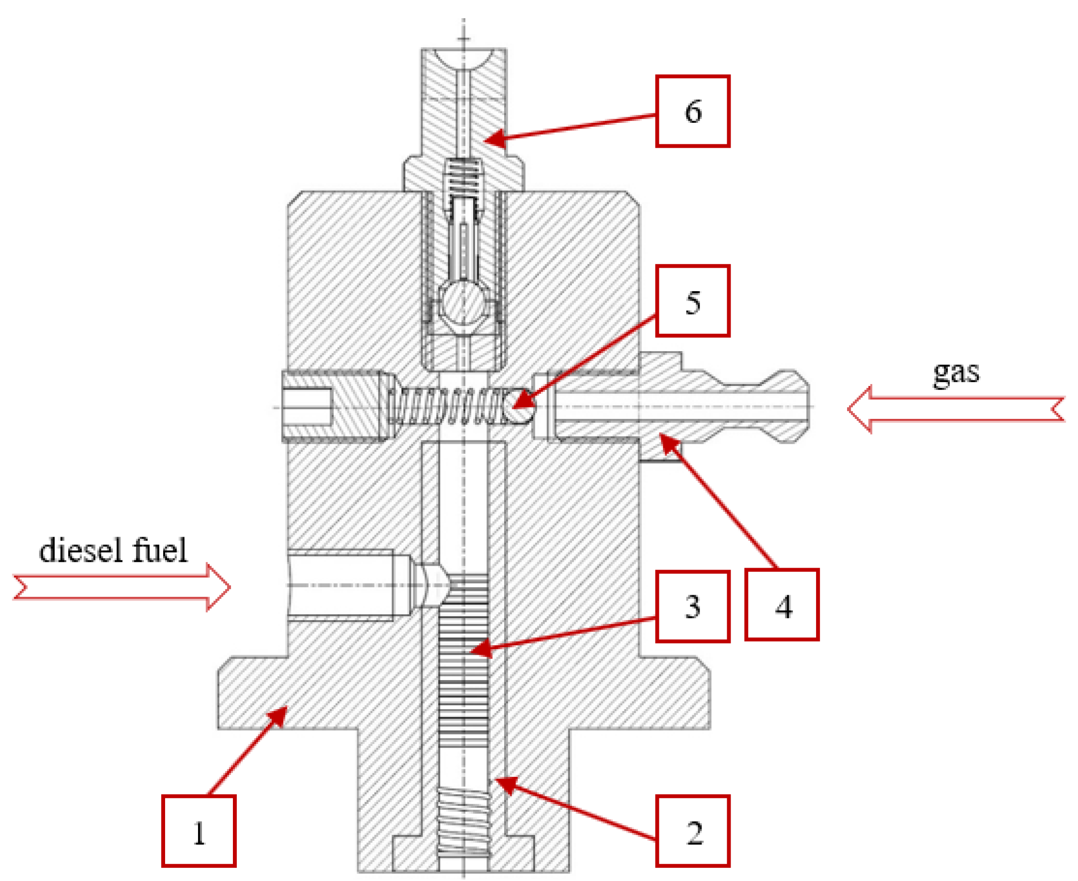
When a small amount of gas is supplied to diesel fuel, the bulk modulus changes drastically compared to conventional fuel. An example is the presence of air in the fuel: if 1% of the volume is occupied by air, the bulk modulus of a typical liquid reduces by approx. 50% [34]. Due to a significantly greater ability of exhaust gas to dissolve in petroleum-derived fuels compared to air, one should expect the value of the bulk modulus to change even more. An additional aspect arises: as the engine load changes, the exhaust gas composition is modified, including the content of CO2. Therefore, in the investigations of the coefficient of solubility and bulk modulus of a solution of fuel and exhaust gas, one needs to allow for the amount of exhaust gas as well as its composition.
In order to determine the amount of gas that can be dissolved in the fuel, a quantity of q was adopted that denotes the number of grams that dissolves in 100 g of pure solvent at a given temperature when the total pressure (partial pressure of saturated steam over liquid) at the temperature of absorption amounts to 760 mm Hg. The coefficient of solubility q is a function of pressure and temperature. The influence of the temperature on the q value is not evident and depends on the combination of the type of gas and the type of solvent. As for the pressure, the direction of the change in the q value is clear. An increase in the pressure improves the ability of solvents to dissolve gases [35]. The method of measurement of the coefficient of solubility is based on the above definition—the measurement was performed in such a way that in the volume V , a known amount of gas of the mass of m g (in this case, V g = V ) was confined and then liquid was introduced to this volume. Filling the entire volume with liquid forced the passage of the gas into the liquid (the process of dissolution). The mass of the liquid in which this occurred, in connection with the mass of gas m g , allows determining the coefficient of solubility.
The process of dissolution is accompanied by an increase in the pressure triggered by the introduction of liquid into a constant volume V and a constant mass m g . Until the entire amount of gas is dissolved, the analyzed volume is divided into two parts. One of these parts contains the gaseous phase and the other contains the liquid phase (a solution of liquid and gas). In the part occupied by the gas, compression takes place and the pressure changes according to a curve resembling an isothermal one. In the part filled with liquid, the change in volume results from the compressibility of the solution, and the accompanied relation of the pressure change is close to a straight line. Hence, the function describing the changes in the pressure during the dissolution of exhaust gas in diesel fuel is monotonic and the curve changes from exponential to a straight line, which is an asymptote. The point of passing of the curve into an asymptote corresponds to the moment when the entire amount of gas passes into the solution.
The bulk modulus B of the liquid determines the proneness of the liquid to deformation caused by the pressure p and is the opposite of compressibility β defined with the formula [34,36]:
β = 1 V d V d p T , S
where V is the volume in which the pressure p is acting. Depending on the conditions under which the compressibility measurement is performed, we can distinguish a notion of isothermal and adiabatic compressibility, which is indicated by the temperature T or the entropy indexes S . The sign ‘−’ denotes the direction of the changes in volume caused by the increase in the pressure. In calculations of hydraulic systems, the change in the measurement conditions is neglected and the bulk modulus of a liquid B is used in the equation [37]:
d V V = d p B
From the above relation, it results that
B = V · d p d V
This equation can be construed as a definition of the bulk modulus. The dimension of the modulus is Pascal.
From the definition of the bulk modulus, it is determined how the measurement should be made: the volume V must be modified and the resulting change in pressure d p must be measured at the same time. In the measurements, infinitely small increases are replaced with finite ones Δ . Given the very high values of B , in order to obtain sufficient accuracy of the measurement, the volume V should be equally high. Assuming the linear function B p , two points suffice.

2.2. Research Stand

In the presence of gas, the value of B from Formula (3) becomes significantly complicated. In the pressure range of interest, from the point of view of the injection process, gas usually dissolves in the diesel fuel entirely and is trapped in the solution, whose solvent is the fuel. Hence, the design of the test stand must allow for the dissolution phase. When building the stand for the measurement of the bulk modulus, the authors decided to utilize a tank of a constant volume V (Figure 2) and carry out the dissolution by changing the mass of the fuel in the tank. The fuel system was composed of a conventional pump (4) driven by a lever (7), a high-pressure line (8), an injector (3) and a fuel tank (6). The changes in the pressure in the hydraulic actuator were recorded with a manometer (9). The fuel pumping was carried out by a manual drive of component (4) in Figure 2.
In the beginning of the measurement, the entire volume V m a x was filled with exhaust gas of known content of CO2, i.e., the exhaust mass m e of the volume V e = V was introduced and was not modified during the measurement. Next, using the high-pressure system, diesel fuel was introduced into this volume. As the diesel fuel was supplied to the volume V f , an increase in the pressure in the fuel tank and the compression of the exhaust gas took place, leading to a reduction in V e occupied by the gaseous phase of the exhaust and the process of dissolution; exhaust gas mass m e did not change. Upon obtaining the counterbalance pressure, adequate for the introduced mass of the exhaust gas, the gaseous phase faded (the entire mass of the exhaust gas in the measured volume passed into the liquid state), and when continuing the fuel delivery to the measured volume, effects triggered by the liquid compressibility were observed.
The relation of the bulk modulus and the amount of dissolved exhaust gas was monitored in such a way that for each measurement, the same amount of exhaust gas V m a x was taken, and then, by changing the position of piston 2, the measured volume V was determined, which was later filled with diesel fuel. In order to ensure the tightness of the measured volume, diesel fuel was supplied under the piston under the counterbalancing pressure p r .
The nature of the pressure changes observed in this process is shown in Figure 3. The equilibrium state for the solution (end of exhaust gas dissolution) occurs at point K. The observed nature of the pressure changes in this area is typical of a liquid compression (in this case, it is a solution). The bulk modulus can be calculated based on the adopted two points on a straight line. These are example points A and B. Point B must be above point K.
The increase in the fuel volume Δ V A B generates a pressure change in the volume V by Δ p A B ; hence, the bulk modulus can be calculated as:
B = V · Δ p A B Δ V A B
The most important component of the measurement system shown in Figure 4 is the hydraulic actuator (Figure 2) composed of a cylinder and a piston. The position of the piston can be changed, thus setting the measured volume V . The filling of the cylinder with gas is realized through an inlet hole during the downward movement of the piston. Upon filling the volume V m a x with gas, the inlet hole is closed.
An important problem to be addressed was the tightness of the hydraulic actuator because during the measurements, the mass of the supplied gas had to be constant. This problem was solved in two ways. The first solution was a specially designed sealing of the piston inside the cylinder. The second solution was the application of the volume under the cylinder to generate a counter pressure (the pressure under the cylinder p r , Figure 2). When pumping the fuel to the space above the piston, the space under the cylinder was filled with diesel fuel, maintaining the pressure close to that above the piston. The maximum difference in the pressures below and above the piston did not exceed 0.5 MPa.
As a result of the measurements, a discrete form of the function p m f u e l V was obtained. Assuming the string of values Δ V , a set of curves was obtained that served to determine the pressure corresponding to the moment of full dissolution of a constant amount of gas in a variable amount of fuel. This is the point at which the curve p m f u e l V becomes a straight line. Based on the determined points A and B (Figure 3), a discrete form of the relation q p g a s for the tested gas was obtained.
In order to determine the coefficient of solubility, measurements were carried out for a predefined position of the piston h : 0, 50, 100, 150, 200, 250, 270 and 290 mm, corresponding to the measured volume Δ V 1508.0, 1256.6, 1005.3, 754.0, 502.7, 251.3, 150.8 and 50.3 cm3, respectively.
The measurement cycle (for all positions of the piston) was carried out taking the exhaust gas to the hydraulic cylinder directly from the exhaust manifold of a turbocharged diesel engine (compare Figure 4) operating near the test stand. The measurements were performed for three predefined concentrations of CO2 in the exhaust gas: 4%, 8% and 10%. The adopted concentrations were obtained by changing the engine load. The concentration of CO2 in the exhaust gas was measured with a TESTO 360 analyzer (the analyzer enables a simultaneous measurement of the values of CO, CO2, NO, NO2, SO2 and O2 in the exhaust gas).
Taking the volume Δ V m a x of the gas and then modifying this volume to the value Δ V under isothermal conditions without the loss of mass of the gas results in a change in pressure according to the equation:
p · Δ V =   m g a s R T = c o n s t .
This equation allows determining the initial value of the pressure in the measured volume. Supplying fuel to the constant volume Δ V reduces the volume V g occupied by the gas and results in an increase in the pressure. This leads to an increase in the coefficient of solubility and a passage of part of the gas from the volume V g to the solution. If the entire process takes place under conditions close to isothermal, in the initial phase of fuel supply, the curve p m f u e l V describing the course of pressure in the measured volume is close to a straight line. The direction coefficient of this straight line is described with the process of gas compression and reduction in the mass of the part of gas that did not pass into the liquid. As the volume occupied by the gas decreases and the pressure grows, the effect of compression takes over the effect of dissolution, and the direction coefficient of the straight line p m f u e l V increases to the boundary value. When the entire mass of gas dissolves in the fuel, in the analyzed volume, we only have a liquid solution of gas and fuel. With a sufficient amount of solution, supplying a small amount of fuel triggers the same effect as the reduction in the volume. Therefore, the boundary coefficient of the straight line inclination results from the coefficient of compressibility of the fuel gas solution. Such nature of the function p m f u e l V (identical to the one described above) has been observed in all measurements.

3. Results of the Measurements and Discussion

3.1. Coefficient of Solubility

When directly measuring the dissolution of exhaust gas in diesel fuel for all the concentrations of CO2, curves of similar course were recorded. In the paper, the authors gave just one example set of results (Figure 5), for the concentration of CO2 = 4%. On all curves, the initial, approximately straight-line nature of the allocation passes into a phase of heavy non-linearity and then asymptotically approximates a straight line—describing the compressibility of the liquid solution.
All results obtained during the measurements were used to determine the points of coordinates p m f u e l V , at which the process of gas dissolution in the fuel was completed. On each dissolution curve, this point is the beginning of the straight-line portion, covering the compression of a pure liquid. For example, for the curve h = 0 (Figure 5), it was marked K. The mass of the drawn exhaust gas was calculated using the equation of state based on the volume Δ V m a x of the hydraulic cylinder and the physical conditions during the filling of the cylinder (measurement T, p).
Determining these points allowed completing the objective of this part of the research, i.e., determine the set of values of the coefficient of solubility q and matching the values of the pressure p . Based on such results, a descriptive form was created of the characteristics of changes in the coefficient of solubility of exhaust gas in diesel fuel as a function of pressure (Figure 6).
The scope of the research was limited to the conditions (type of gas, intervals of the pressure values) under which the operation of a diesel engine is most likely. The measurements were performed under stationary conditions—the measurements did not allow for the dynamic characteristics of the engine fueling system operation.
In order to dissolve 1 g of air in 100 g of diesel fuel under atmospheric conditions, it is necessary to apply a pressure of the order of 16 MPa [35]. This result confirms the generally known fact of poor gas solubility in liquids compared to the solubility of liquids in liquids. In the engine filling balance, the amount of air dissolved in the fuel referring to the amount of air supplied to the engine via the fueling system is negligibly small, because, under stoichiometric conditions, in order to burn 1 kg of fuel, we need approx. 14.4 kg of air.
With the content of CO2 on the level of approx. 10%, the value of the coefficient of solubility of the exhaust gas increases approximately 100 times compared to the coefficient of solubility of air. Such a significant increase in the coefficient is to be mainly attributed to the presence of CO2. There are other gaseous components in exhaust gas, such as CO or NOx, but their amounts are negligible.
For greater values of the coefficient of solubility, i.e., for q greater than approx. 0.5 ggas/100 gfuel, curves q p of the investigated gases assume a straight line.
The value of pressure at which the entire volume of the gas is dissolved in the fuel depends on the amount of gas. It is advantageous that when supplying gas under ambient conditions, its dissolution occurs at a moderate pressure (lower than that of the injection needle opening in conventional fueling systems). This observation allows a supposition that for the entire operation of the engine (except engine start), in the injection system under high pressure, the gas should remain dissolved in the fuel, therefore not disturbing the operation of the injection systems with airlocks.
However, it is not advantageous that with the increase in the engine load (increase in the content of CO2 in the exhaust gas), the counter pressure decreases, assuming values lower than those of the combustion chamber. Under such conditions, the gas will not release from the solution. In order to generate pressures higher than the maximum combustion pressure, it is necessary to increase the value of the coefficient of solubility. This means that for a given dose of fuel injected during a single engine cycle, the concentration of carbon dioxide in the exhaust gas must be increased.

3.2. Coefficient of Compressibility

The value of the bulk modulus of the fuel mixed with the exhaust gas was determined using a high-pressure system and a test stand, presented in Figure 4. The results of the measurements are shown in the form of graphs in Figure 7, Figure 8 and Figure 9.
On these graphs, the position of point K was ascertained first (end of the process of exhaust gas dissolution) and then two points A and B were assumed, between which the increase in the amount of fuel Δ V A B supplied to the measured volume and the corresponding increase in the pressure Δ p A B were recorded.
The recorded allocation of Δ V A B and Δ p A B is the result of the influence of the compressibility of the solution and the deformation of the entire equipment. With such high pressures and the relatively great size of the high-pressure system, the problem of deformation can be neglected. When estimating the rigidity of the components of the said system, the authors concluded that the rigidity of the frame was at least 10 times greater than the rigidity of the outstanding components, which is why the deformation of the frame was omitted. However, the radial deformation of the cylinder along with the longitudinal deformation of the piston/piston pusher position adjustment screw were taken into account. The results of the measurements of the bulk modulus of the solution of diesel fuel and exhaust gas, allowing for the deformation of the measurement system, are shown in Figure 10.
The coefficient of compressibility shows a value of a relative decrease in volume generated by the increase in pressure. Changes in the bulk modulus obtained in the tests vary widely and assume a non-linear form (Figure 10). The compressibility/bulk modulus decreases with the increase in the mass of the exhaust gas drawn into the cylinder. This is caused by the intermolecular interaction; the repulsive forces are significant only when the molecules are very close to one another. Probably, these are close-range interactions; even on the scale determined by the diameter of the molecules, the repulsion becomes significant when the molecules are intermediately close to one another, as is the case under high pressure when a large number of molecules occupy a small volume. Such a situation can be observed when the piston of the hydraulic actuator is in the top position ( h = 0 ) (Figure 10).

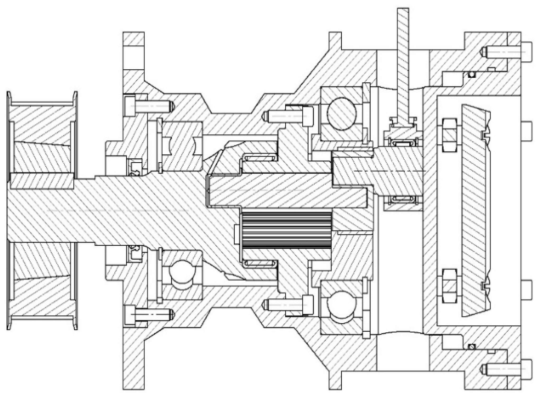
4. A Pump with a Hypocycloidal Drive

In order to obtain a homogenous solution of an equilibrium state to induce the desorption effect, it is necessary to effectively compress the gas to a volume occupied by the liquid fuel. It was assumed that this would take place in the pumping section of the pump of a sufficiently high displacement of the piston. The determined values of the coefficient of solubility and compressibility of the solution of diesel fuel and exhaust gas allowed determining the minimum size of the pumping sections of the high-pressure pump. The performed research has shown that CO2 is a gas of high coefficient of solubility. It is important to supply it in such an amount as to obtain the equilibrium state of the saturated solution at a pressure equal to the pressure in the fuel rail. This means that the pump should have large volumes of the pumping sections. Apart from the size of the pumping section, an important parameter was also the total size of the pump—it was generally assumed that the pump should be of a compact size, similar to other pumps available on the market.
Meeting these requirements forced the application of an entirely new solution. Owing to the above, the authors decided to apply the hypocycloidal drive [38,39,40]. A hypocycloidal drive is composed of two wheels, the larger of which (R) has an inner toothing and the smaller (r) has an outer one. The torque is supplied to the smaller wheel, setting it in motion, while the larger wheel does not move against the axis. The smaller wheel moves on the circumference of the larger wheel, and a selected point on the radius of the smaller wheel draws a curve referred to as the cycloid. In order to create the actuating drive of the pump, a hypocycloidal gearset was applied, of the radius ratio of the toothed wheels R/r = 2. Such a selection of the wheels allows obtaining a resultant rectilinear motion, which results from the Copernicus theorem: ‘a point on the circumference of the small circle traces a straight line segment—a diameter of the large circle’. Figure 11 presents the schematics of operation of the gearset together with the marked straight line, on which the radial element of the mechanism moves.
The analysis of the motion of the driving element indicates that, similarly to the crosshead mechanism, it generates motion whose velocity can be described with a sine function. A parametric equation describing the position of a point as a function of rotation angle can be determined as follows:
x α = R r cos α + r cos R r r α
x α = R r sin α r sin R r r α
Utilizing the above drive concept, the authors developed the design of the pump from scratch. This solution has been patented. In this respect, several variants have been prepared, fitted with one to four pumping sections. The paper presents the simplest one based on a single pumping section.
The novel pump (Figure 12) has a main shaft (1), to which the drive is connected. In the shaft, a countershaft is fixed eccentrically (2) in such a fashion that both these components can move against each other. On the countershaft, a toothed wheel is located, having outer teeth that mate with the toothed wheel (3) fixed to the pump casing. The support (4) is an element that mates with the countershaft from the side of the pumping section. Additionally, inside the countershaft, a mandrel is fixed eccentrically (5) that mates with the mount (6) through a bearing. The casing has a fixed piston or a plunger (7) along with the guiding element fitted in a sliding fashion inside the cylinder of the pumping section. The main shaft, the support and the mandrel have bearings (Figure 13). A detailed description of the design has been presented in [41,42,43].
Given the possibility of utilizing the desorption effect, an important component is the pumping section. This is the location where the gas dissolution in the fuel is to occur; hence, an appropriate design is needed to ensure this process. An example solution of the pumping section is shown in Figure 14. The main components of the section are the body of the delivery (1), the (2) and the piston. As the piston moves downwards in the volume of the pumping section, a vacuum is generated, the result of which is the displacement of the spring and the ball (a one-way gas valve, 5), and the space above the piston is filled with the drawn gas. When the edge of the piston discloses the duct supplying the fuel under pressure that mixes with the gas contained inside the cylinder and initially compresses it, the filling of the section takes place. As a result, the gas valve closes. The upward movement of the piston causes a closure of the duct supplying the fuel and ends the compression of the mixture. During the compression, the gas dissolves in the fuel, making a solution or a mixture. When the initial pressure of the spring of the pumping valve (6) is overcome, the mixture is pumped to the pressure line and then the pressure accumulator.
The presented design of a hypocycloidal pump has a variety of advantages. The authors assume that this design will be more reliable and durable compared to traditional solutions. This results from the application of verified, strong materials (toothed wheels, bearings).
The fundamental advantage of the design allowing the application of the effect of desorption is the high piston displacement. The displacement can be changed depending on the needs by modifying the dividing diameter of the large toothed wheel (the displacement of the piston equals the diameter of the wheel). In the prototype version, for the assumed gearset module equal to 1, the displacement was 40 mm. This allows obtaining a large fuel rate per single cycle, which reduces the forces in the pump mechanism. A larger piston also means a longer pumping section. This, in turn, allows an application of a double labyrinth seal (Figure 14, component 3) additionally fitted with a channel draining the leaking fuel (e.g., to the overflow line of the injectors). This allows minimizing the leak of the diesel fuel to the lubricating medium below. A double labyrinth seal has another significant advantage. The inventors of the pump decided to separate the pumping function from the lubricating function. The pump components are to be lubricated with a transmission fluid. This will allow the pump to operate with alternative fuels.
Within the scope of works on the design of the pump, a series of simulations have been performed [45]. The works have proven that when a hypocycloidal drive is used, lateral forces are eliminated in the piston–cylinder assembly of the pumping section, and thus an advantageous distribution of forces was obtained compared to traditional cam drives. The simulations have also proven an advantageous course of the driving moment on the pump shaft—these parameters had greater values compared to cam-driven pumps. This is an important advantage, particularly in terms of gas dissolution in liquids taking place in the pumping section.
Minimizing the lateral forces is good for the application of ceramic materials on the mating surfaces of the piston and the cylinder. A characteristic feature of ceramic materials is their hardness and the resulting resistance to wear. The modeling of the pump design presented in [46] confirmed the superiority of ceramic materials over conventional steels applied in the pumping sections. Therefore, this is a particularly interesting alternative (owing to the minimization of the lateral forces in the piston–cylinder assembly) that can be applied in the hypocycloidal pump.
The patented prototype of the pump is in the phase of production. In the beginning of 2023, tests are planned that will allow a practical validation of the design.

5. Conclusions and Trends in Future Works

In order to improve diesel engine operating indexes through enhancing the atomization process, the authors proposed the application of the effect of desorption of gas from a solution with a nucleation of the gas bubbles. This concept includes dissolution of exhaust gas in diesel fuel, which, during the process of injection, leads to an abrupt release of the gas from the solution as a result of a sudden drop in the thermodynamic potential. The said mechanism triggers a tearing process of the droplets from the inside. This is an additional factor boosting the atomization mechanism.
The realization of the process requires a new design of the pump that would enable dissolution of the exhaust gas in the fuel with the help of the pumping section. In order to properly design such a pumping section, it was necessary to investigate the properties of the solution of the fuel with the gas. To this end, a test stand was built that allowed determining the coefficient of solubility and compressibility of exhaust gas in diesel fuel. The results of the investigations determined the coefficient of solubility of different concentrations of CO2 in the fuel and the influence of the amount of exhaust gas dissolved in the fuel on the bulk modulus of the solution. The obtained results confirm the adequate solubility of carbon dioxide in the fuel. It is noteworthy that the coefficients of solubility and compressibility of the solution of diesel fuel with exhaust gas were determined based on the assumption that these processes take place under isothermal and quasi-statistical conditions. In general, the bulk modulus and the coefficient of solubility are functions of pressure and temperature, which is why the performed investigations and analyses did not fully exhaust the described problem.
The concept is supplemented with the design of the pump generally described in the second part of the paper. In terms of the possibility of realization of the effect of desorption, the most crucial feature of the pump is the piston displacement in the pumping section. In the prototype version, it reaches 40 mm. According to the preliminary estimations, this is sufficiently high for a full dissolution of exhaust gas in the fuel. This aspect is subject to further research. It is, however, important that the displacement can be modified, as it equals the dividing diameter of the large toothed wheel in a hypocycloidal gearset.

Author Contributions

Conceptualization, M.B. and W.K.; methodology, M.B. and W.K.; software, W.K. and R.S.; validation, M.B., W.K. and R.S.; formal analysis, M.B. and W.K.; investigation, M.B., W.K. and R.S.; resources, M.B., W.K. and R.S.; data curation, W.K. and R.S.; writing—original draft preparation, W.K. and M.B.; writing—review and editing, W.K.; visualization, W.K.; supervision, W.K. and M.B.; project administration, W.K.; funding acquisition, W.K. All authors have read and agreed to the published version of the manuscript.

Funding

Ministry of Education and Science, Research Subsidy, 0415/SBAD/0337.

Institutional Review Board Statement

Not applicable.

Informed Consent Statement

Not applicable.

Data Availability Statement

The data presented in this study are available on request from the corresponding author.

Conflicts of Interest

The authors declare no conflict of interest.

References

  1. Jasiński, R.; Galant-Gołębiewska, M.; Nowak, M.; Kurtyka, K.; Kurzawska, P.; Maciejewska, M.; Ginter, M. Emissions and Concentrations of Particulate Matter in Poznan Compared with Other Polish and European Cities. Atmosphere 2021, 12, 533. [Google Scholar] [CrossRef]
  2. Jasiński, R.; Galant-Gołębiewska, M.; Nowak, M.; Ginter, M.; Kurzawska, P.; Kurtyka, K.; Maciejewska, M. Case Study of Pollution with Particulate Matter in Selected Locations of Polish Cities. Energies 2021, 14, 2529. [Google Scholar] [CrossRef]
  3. Basińska, M.; Ratajczak, K.; Michałkiewicz, M.; Fuć, P.; Siedlecki, M. The Way of Usage and Location in a Big City Agglom-eration as Impact Factors of the Nurseries Indoor Air Quality. Energies 2021, 14, 7534. [Google Scholar] [CrossRef]
  4. Gawron, B.; Białecki, T.; Janicka, A.; Górniak, A.; Zawiślak, M. An innovative method for exhaust gases toxicity evaluation in the miniature turbojet engine. Aircr. Eng. Aerosp. Technol. 2017, 89, 757–763. [Google Scholar] [CrossRef]
  5. Feng, R.; Li, G.; Sun, Z.; Hu, X.; Deng, B.; Fu, J. Potential of emission reduction of a turbo-charged non-road diesel engine without aftertreatment under multiple operating scenarios. Energy 2023, 263, 125832. [Google Scholar] [CrossRef]
  6. Feng, R.; Hu, X.; Li, G.; Sun, Z.; Deng, B. A comparative investigation between particle oxidation catalyst (POC) and diesel particulate filter (DPF) coupling aftertreatment system on emission reduction of a non-road diesel engine. Ecotoxicol. Environ. Saf. 2022, 238, 113576. [Google Scholar] [CrossRef]
  7. Kozak, M.; Lijewski, P.; Waligórski, M. Exhaust Emissions from a Hybrid City Bus Fuelled by Conventional and Oxygenated Fuel. Energies 2022, 15, 1123. [Google Scholar] [CrossRef]
  8. Merkisz, J.; Siedlecki, M. Specific emissions analysis for a combustion engine in dynamometer operation in relation to the thermal state of the exhaust gas aftertreatment systems in a modified NRSC test. MATEC Web Conf. 2017, 118, 27. [Google Scholar] [CrossRef] [Green Version]
  9. Jasiński, R. Number and mass analysis of particles emitted by aircraft engine. MATEC Web Conf. 2017, 118, 23. [Google Scholar] [CrossRef] [Green Version]
  10. Sawczuk, W.; Merkisz-Guranowska, A.; Rilo Cañás, A.-M. Assessment of disc brake vibration in rail vehicle operation on the basis of brake stand. Eksploat. Niezawodn. 2021, 23, 221–230. [Google Scholar] [CrossRef]
  11. Sawczuk, W.; Ulbrich, D.; Kowalczyk, J.; Merkisz-Guranowska, A. Evaluation of Wear of Disc Brake Friction Linings and the Variability of the Friction Coefficient on the Basis of Vibroacoustic Signals. Sensors 2021, 21, 5927. [Google Scholar] [CrossRef] [PubMed]
  12. Kałużny, J.; Waligórski, M.; Szymański, G.M.; Merkisz, J.; Różański, J.; Nowicki, M.; Al Karawi, M.; Kempa, K. Reducing friction and engine vibrations with trace amounts of carbon nanotubes in the lubricating oil. Tribol. Int. 2020, 151, 1–27. [Google Scholar] [CrossRef]
  13. Pielecha, I. The influence of petrol injection parameters on the structure of geometry of fuel spray injected from outward-opening injectors. Fuel 2018, 222, 64–73. [Google Scholar] [CrossRef]
  14. Ye, P.; Sun, C.; Lapuerta, M.; Agudelo, J.; Wal, R.V.; Boehman, A.L.; Toops, T.; Daw, S. Impact of rail pressure and biodiesel fueling on the particulate morphology and soot nanostructures from a common-rail turbocharged direct injection diesel engine. Int. J. Engine Res. 2014, 17, 193–208. [Google Scholar] [CrossRef]
  15. Meek, G.A.; Williams, R.; Thornton, D.; Knapp, P.; Cosser, S. F2E—Ultra High Pressure Distributed Pump Common Rail System. SAE Tech. Pap. 2014, 1–8. [Google Scholar] [CrossRef]
  16. Wloka, J.; Pflaum, S.; Wachtmeister, G. Potential and Challenges of a 3000 Bar Common-Rail Injection System Considering Engine Behavior and Emission Level. SAE Int. J. Engines 2010, 3, 801–813. [Google Scholar] [CrossRef]
  17. Oki, M.; Matsumoto, S.; Toyoshima, Y.; Ishisaka, K.; Tsuzuki, N. 180MPa Piezo Common Rail System. SAE Tech. Pap. 2006, 1–10. [Google Scholar] [CrossRef]
  18. Petkar, R.M.; Kardile, C.A.; Deshpande, P.V.; Isenburg, R.; Soorajith, R. Influence of Increased Diesel Fuel Spray Velocities and Improved Spray Penetration in DI Engines. SAE Tech. Pap. Ser. 2006, 1–8. [Google Scholar] [CrossRef]
  19. Yue, Z.; Reitz, R.D. An equilibrium phase spray model for high-pressure fuel injection and engine combustion simulations. Int. J. Engine Res. 2019, 20, 1–13. [Google Scholar] [CrossRef]
  20. Beck, J.C.; Watkins, A.P. The simulation of fuel sprays using the moments of the drop number size distribution. Int. J. Engine Res. 2004, 5, 1–21. [Google Scholar] [CrossRef]
  21. Kang, J.; Bae, C.; Lee, K.O. Initial development of non-evaporating diesel sprays in common-rail injection systems. Int. J. Engine Res. 2003, 4, 283–298. [Google Scholar] [CrossRef]
  22. Ferrari, A.; Vitali, R. Instantaneous torque, energy saving and flow rate ripple analysis of a common rail pump equipped with different delivery-pressure control systems. Int. J. Engine Res. 2017, 19, 1036–1047. [Google Scholar] [CrossRef]
  23. Magryta, P.; Geca, M. FEM analysis of piston for aircraft two stroke diesel engine. MATEC Web Conf. 2019, 252, 1–6. [Google Scholar] [CrossRef]
  24. Bor, M.; Borowczyk, T.; Karpiuk, W.; Smolec, R. Determination of the response time of new generation electromagnetic injectors as a function of fuel pressure using the internal photoelectric effect. In Proceedings of the 2018 International Interdisciplinary PhD Workshop (IIPhDW), Swinoujscie, Poland, 9–12 May 2018; 2018; pp. 335–339. [Google Scholar] [CrossRef]
  25. Sanda, J.; Wada, Y.; Fujimoto, H. Improvement of combustion and emissions in diesel engines by means of enhanced mixture formation based on flash boiling of mixed fuel. Int. J. Engine Res. 2008, 9, 15–27. [Google Scholar] [CrossRef]
  26. Kwak, K.H.; Jung, D.; Borgnakke, C. Enhanced spray and evaporation model with multi-fuel mixtures for direct injection in-ternal combustion engines. Int. J. Engine Res. 2014, 15, 488–503. [Google Scholar] [CrossRef]
  27. Battino, R.; Clever, H.L. The Solubility of Gases in Liquids. Chem. Rev. 1966, 66, 395–463. [Google Scholar] [CrossRef]
  28. Merkisz, J.; Pielecha, J.; Pielecha, I. Road Test Emissions Using On-board Measuring Method for Light Duty Diesel Vehicles. Jordan J. Mech. Ind. Eng. 2011, 5, 89–96. [Google Scholar]
  29. Merkisz, J.; Bajerlein, M.; Kozak, W. Dissolving Oxygen in Diesel Fuel as a Way to Make Road Transport More Environ-mentally Friendly. WIT Trans. Built Environ. 2008, 101, 325–334. [Google Scholar] [CrossRef] [Green Version]
  30. Merkisz, J.; Bajerlein, M.; Kozak, W.; Markowski, J. The Influence of CNG Dissolved in the Diesel Fuel on the Combustion Process and Concentration of Toxic Compounds in Exhaust Gas. SAE Tech. Pap. 2008, 1–10. [Google Scholar] [CrossRef]
  31. Ma, X.; Abe, Y.; Kaneko, A.; Fujimoto, S.; Murakami, C. Study on Dissolution Process of Liquid CO2 into Water under High Pressure Condition for CCS. Energy Procedia 2017, 114, 5430–5437. [Google Scholar] [CrossRef]
  32. Kozak, W.; Bajerlein, M.; Markowski, J. Verification of the concept of spray mechanism assisted with air dissolved in diesel oil. Combust. Engines 2006, 124, 21–37. [Google Scholar] [CrossRef]
  33. Battino, R.; Rettich, T.R.; Wilhelm, E. Gas Solubilities in Liquid Water Near the Temperature of the Density Maximum, Tmax (H2O) = 277.13 K. Monatsh. Chem. 2018, 149, 219–230. [Google Scholar] [CrossRef]
  34. Bankowski, K.; Gajewska, I. (Edited by) Physicochemical Guide (Original: Poradnik Fizykochemiczny), 2nd ed.; WNT: Warsaw, Poland, 1974; p. 415. [Google Scholar]
  35. Kozak, W. Shaping Injection Parameters for Compression-Ignition Engines (Original: Ksztaltowanie Parametrow Wtrysku do Silnikow o Zapłonie Samoczynnym); No 427; Poznan Univeristy of Technology Publishing House: Poznan, Poland, 2008; pp. 43–67. [Google Scholar]
  36. Guillon, M. Theory and Calculation of Hydraulic Systems; WNT: Warsaw, Poland, 1966; p. 108. (In Polish) [Google Scholar]
  37. Atkins, P.; De Paula, J. Physical Chemistry, 9th ed.; W. H. Freeman and Company: New York, NY, USA, 2010; p. 718. [Google Scholar]
  38. Xu, X.; Xu, H.; Deng, H.; Gu, F.; Talbot, C. An Investigation of a Hypocycloid Mechanism Based Twin-Rotor Piston Engine. J. Mech. Eng. Sci. 2015, 229, 106–115. [Google Scholar] [CrossRef] [Green Version]
  39. Aziz, E.S. Enhanced Hypocycloid Gear Mechanism for Internal Combustion Engine Applications. J. Mech. Des. 2016, 138, 125002. [Google Scholar] [CrossRef]
  40. ElBahloul, M.A.; Aziz, E.S.; Chassapis, C. Mechanical Efficiency Prediction Methodology of the Hypocycloid Gear Mechanism for Internal Combustion Engine Application. Int. J. Interact. Des. Manuf. 2019, 13, 221–233. [Google Scholar] [CrossRef]
  41. Bajerlein, M.; Karpiuk, W.; Smolec, R. Use of Gas Desorption Effect in Injection Systems of Diesel Engines. Energies 2021, 14, 244. [Google Scholar] [CrossRef]
  42. Bajerlein, M.; Bor, M.; Karpiuk, W.; Smolec, R.; Spadło, M. Strength analysis of critical components of high-pressure fuel pump with hypocycloid drive. Bull. Pol. Acad. Sci. Tech. Sci. 2020, 68, 1341–1350. [Google Scholar] [CrossRef]
  43. Bor, M.; Borowczyk, T.; Idzior, M.; Karpiuk, W.; Smolec, R. Analysis of hypocycloid drive application in a high-pressure fuel pump. MATEC Web Conf. 2017, 118, 00020. [Google Scholar] [CrossRef] [Green Version]
  44. Karpiuk, W. Cavitating Fuel Flows in Hypocycloid Pump from the Perspective of Applying the Effect of Gas Desorption from The Solution with Nucleation of Gas Bubbles. Adv. Sci. Technol. Res. J. 2020, 14, 56–66. [Google Scholar] [CrossRef]
  45. Bor, M.; Borowczyk, T.; Karpiuk, W.; Spadło, M.; Smolec, R. Concept of a pump for diesel engines fuel supply using hypocycloid drive. In IOP Conference Series: Materials Science and Engineering; IOP Publishing: Bristol, UK, 2018; Volume 421, p. 042034. [Google Scholar] [CrossRef]
  46. Bor, M.; Karpiuk, W.; Krakowiak, M.; Borowczyk, T.; Smolec, R. Assessment of the Possibility of Applying Ceramic Materials in Common Rail Injection Systems. Adv. Sci. Technol. Res. J. 2018, 12, 312–321. [Google Scholar] [CrossRef]
Figure 1. Concept of assisted atomization based on the desorption effect.
Energies 15 09163 g001
Figure 2. Diagram of the method of measurement of the coefficient of solubility and bulk modulus: 1—cylinder of the hydraulic actuator, 2—piston of the hydraulic actuator, 3—injector, 4—pump, 5—pump supplying the fuel under the piston, 6—fuel tank, 7—pump lever, 8—high pressure line, 9—manometer, 10—manometer measuring the pressure under the piston ( p r ).
Energies 15 09163 g002
Figure 3. Presentation of the method of measurement of the coefficient of solubility and bulk modulus B of the solution of diesel fuel and exhaust gas: A—measurement end point, B—measurement start point, K—end of exhaust gas dissolution, Δ p A B —change in pressure on the AB portion, Δ V A B —change in volume on the AB portion.
Energies 15 09163 g003
Figure 4. Diagram of the diesel fuel/exhaust gas compressibility measurement stand: 1—frame with hydraulic actuator, 2—probe (pumping section of the injection pump), 3—combustion engine, 4—exhaust gas analyzer probe, 5—exhaust gas analyzer, 6—control panel, 7—extraction system, 8—fuel tank, 9—injector, 10—valves (exhaust, supply and bleed valves), 11—manometer, 12—U-pipe, 13—exhaust gas system.
Energies 15 09163 g004
Figure 5. Results of the measurements of the coefficient of solubility of exhaust gas in diesel fuel for the concentration of CO2 in the fuel of 4% (K—end of exhaust gas dissolution).
Energies 15 09163 g005
Figure 6. Results of the measurements of the coefficient of solubility of exhaust gas in diesel fuel under ambient conditions for (tamb = 22 °C, pamb = 1012 hPa).
Energies 15 09163 g006
Figure 7. Change in the pressure in the measured volume at predefined piston positions for the 4% content of CO2 in the exhaust gas.
Energies 15 09163 g007
Figure 8. Change in the pressure in the measured volume at predefined piston positions for the 8% content of CO2 in the exhaust gas.
Energies 15 09163 g008
Figure 9. Change in the pressure in the measured volume at predefined piston positions for the 10% content of CO2 in the exhaust gas.
Energies 15 09163 g009
Figure 10. Effect of the amount of exhaust gas dissolved in diesel fuel on the bulk modulus of the solution.
Energies 15 09163 g010
Figure 11. Principle of operation of a hypocycloidal drive [41].
Energies 15 09163 g011
Figure 12. A simplified model of a hypocycloidal pump showing the most crucial components of the design: 1—main shaft, 2—countershaft, 3—toothed wheel, 4—support, 5—mandrel, 6—mount, 7—plunger.
Energies 15 09163 g012
Figure 13. Diagram of the hypocycloidal pump (no delivery section).
Energies 15 09163 g013
Figure 14. Delivery section of hypocycloid pump: 1—body of the delivery section, 2—cylinder, 3—section labyrinth seal, 4—gas stub pipe, 5—one-way gas valve, 6—one-way outlet valve [44].
Energies 15 09163 g014
Publisher’s Note: MDPI stays neutral with regard to jurisdictional claims in published maps and institutional affiliations.

