Article

Gas Hold-Up in Vessel with Dual Impellers and Different Baffles

by
Marta Major-Godlewska
and
Magdalena Cudak
*
Faculty of Chemical Technology and Engineering, West Pomeranian University of Technology, Szczecin, al. Piastów 42, 71-065 Szczecin, Poland
*
Author to whom correspondence should be addressed.
Energies 2022, 15(22), 8685; https://doi.org/10.3390/en15228685
Submission received: 5 October 2022 / Revised: 14 November 2022 / Accepted: 17 November 2022 / Published: 18 November 2022
(This article belongs to the Special Issue Practical and Scientific Aspects of Multiphase Systems)

Abstract

:
The influence of impellers system, baffles system and type of liquid on gas hold-up in a vessel has been presented in this paper. The analysis of gas hold-up was conducted on the basis of the data obtained in the vessel. The vessel used in the study was of inner diameter D = 0.288 m, and it was filled with liquid up to a height of H = 0.576 m. The vessel used in the study was equipped in four planar standard baffles or 24 vertical tubular baffles located on the circuit. A high-speed impellers system, consisting of two impellers located on the shaft, was used to agitate the liquid. The six gas–liquid systems were tested. The gas used in the study was air. The liquids were distilled water, aqueous solutions of NaCl (concentration c = 0.4 kmol/m3 or 0.8 kmol/m3), aqueous solution of sucrose (concentration c = 2.5% mass., 5% mass.), 5% mass. aqueous solution of sucrose and yeast suspension concentration ys = 1% mass. The obtained set of over 1600 experimental points allowed to derive the equations describing the effect of gas flow number Kg, Weber number We and parameter Y (for air–water and air–aqueous solution of NaCl) and Kg, We, c and ys (for air–water, air–aqueous solution of sucrose and air–yeast suspension–aqueous solution of sucrose) on gas hold-up. These equations do not have equivalents in the literature.

Graphical Abstract

1. Introduction

Gas hold-up is one of the basic parameters characterizing two- or three-phase systems in apparatuses (vessel, air-lift columns) [1,2]. Based on the proportion of gas in the liquid, it is possible to determine how much gas (oxygen) is in the liquid and whether this amount is sufficient to obtain the appropriate conditions for functioning of, e.g., microorganisms (organisms) in a given system. Due to the fact that gas hold-up depends on many factors, it is necessary to carry out research taking into account various parameters (factors) affecting gas hold-up, and it is necessary to analyze the relationship between these parameters (factors) and values of gas hold-up [3,4,5,6,7,8].
The basic operating parameters in vessels that affect the proportion of gas hold-up are the speed impeller and the amount of gas supplied to the system (e.g., the volumetric gas flow rate or the superficial gas velocity). On the basis of experimental studies carried out by many authors, in various systems, it was found that, with an increase in the stirrer rotation frequency and with an increase in the amount of gas supplied to the system, the value of gas hold-up increases [6,7,9,10,11,12,13,14]. Another group of parameters influencing the amount of gas hold-up are physical parameters, e.g., viscosity, density and concentration of individual phases or surface tension [4,6,11,15]. Gas hold-up decreases both with increasing viscosity of the liquid [15] and with increasing surface tension [16]. Khalili et al. [4] found that, assuming a constant Kg value, gas hold-up increases with an increase in the concentration of xanthan gum (an increase in the viscosity of xanthan gum). Moreover, (introducing electrolytes into water, e.g., NaCl) in systems where the liquid phases were aqueous NaCl solutions, an increase in NaCl concentration increases gas hold-up [6,9,11]. The value of the gas hold-up is also influenced by whether or not the system shows the ability to coalesce. Gas hold-up values decrease with an increase in the system’s ability to coalesce [6,9,11,17]. The differences between the values of gas hold-up for systems showing the ability to coalesce and systems with limited ability to coalesce increase with an increase in the superficial gas velocity in the system. In the case of three-phase gas–solid–liquid systems, gas hold-up decreases with increasing concentration of the solid phase in the system [11]. The last largest group of parameters influencing the value of gas hold-up are the geometric parameters. This group includes the quantities characterizing the vessel (height of the liquid, diameter, location of the impeller shaft), the impeller, e.g., the type and number of impellers, diameter, type and number of impeller blades) and baffles (type and number of baffles and their location in the vessel). Impellers were the most frequently analyzed parameters among this group. In the available literature on the subject, one can find many works in which the authors analyzed the type, the number and the arrangement of the impellers in the vessel [4,6,7,9,10,11,14,18,19,20,21,22,23]. Theoretically, the greater the number of impellers in the vessel, the better the mixing or dispersion of phases in such a system. However, adding another impeller increases energy costs. As a standard, it is assumed that the number of impellers in the vessel depends on the height of the liquid in the vessel. In the case of a vessel with a liquid height equal to the vessel diameter, it is one impeller [4,7,9,10,14,18,19,22,23], while subsequent impellers are added when the height of the liquid is greater than the internal diameter of the vessel [6,11,20,21]. In the case of several impellers on the shaft, it was found that the distance between the impellers should be equal to the diameter of the impeller. In such a situation, adequate fluid circulation is obtained in the vessel, produced by each of the impellers [16].
In most of the works available in the literature, standard flat baffles are located in the vessel, and the influence of other parameters on gas hold-up is analyzed [4,7,11,14,21,24,25]. However, it is worth considering and analyzing the replacement of planar baffles with vertical tubular baffles placed in various ways in the vessel, e.g., located on the circle at an equal distance from each other and from the vessel wall, or, e.g., in clusters of several baffles. Detailed results of the study of such baffles were the subject of research [6,9,10,19,20]. In the literature on the subject, there are few studies in which the authors compared the effect of the type of baffles on the value of the gas hold-up [19]. Wan et al. [19] carried out measurements of gas hold-up in a vessel with vertical dual-array tubular coil baffles arranged in groups of four, six or eight or four planar baffles. They found that, in the case of the air–water system, higher values of gas hold-up occur when tubular baffles are installed in the vessel. On the other hand, when there was an aqueous solution of 0.5M Na2SO4 (viscous liquid) in the vessel, better results were obtained for planar baffles due to formation of dead zones around the baffles.
The aim of this work is to determine the influence of selected parameters on gas hold-up in the vessel, in which four standard planar baffles or twenty-four vertical tubular baffles were used interchangeably. The obtained results of the gas hold-up for the vessel–baffle–impeller configurations were then compared in order to determine the influence of the baffles on the value of gas hold-up. In addition, the values of gas hold-up obtained during the experimental studies may constitute a database needed, for example, to verify the results obtained from modeling.

2. Materials and Methods

The measurements for gas–liquid system were conducted in the vessel of inner diameter D = 0.288 m, which was filled with liquid up to the height H = 2D (VL = 3.75 × 10⁻³ m3). The distance of the two impellers from the bottom of the vessel was: for the lower impeller hL = 0.167H, for the upper impeller hU = 0.67H. Gas was dispersed by means of gas sparger. The gas sparger was in the shape of a ring with diameter dg = 0.7d (do = 0.002 m; i = 6), and it was located between vessel bottom and lower impellers e = 0.5hL. Four standard planar baffles (J = 4) were located inside vessel. Other baffles used in the study were vertical tubular baffles in number J = 24 and were arranged symmetrically on the circuit of diameter DB = 0.7D inside the vessel. The outer diameter of a single tube baffle was B = 0.02D. Five different impeller configurations lower (L)—upper (U) high-speed impellers of diameter d = 0.33D were used in the measurements: A315(L)-CD6(u), CD6(L)-A315(U), RT(L)-A315(U), A315(L)-HE3(U), A315(L)-RT(U). Geometrical parameters of the vessel equipped with two impellers and baffles are shown in Figure 1. The located baffles in the vessel are shown in Figure 2. Detailed parameters of the impellers are presented in Table 1.
The gas used in measurement was air. The liquids used in measurement were distilled water, aqueous solutions NaCl of concentration c = 0.4 kmol/m3 and c = 0.8 kmol/m3, aqueous solution of sucrose of concentration c = 2.5% mass., 5% mass., 5% mass aqueous solution of sucrose of concentration and yeast suspension concentration ys = 1% mass.
The ability of gas bubbles to coalesce in the liquid phase of the investigated system was described by Machoň et al. [26] using parameter Y
Y = 2 e x p Ψ +
in Equation (1) Ψ+ = Ψ/Ψcrit, variable Ψ has been defined by Lee and Meyrick [27]
Ψ = Δ σ R T 2 = c d σ d c 2 1 1 + dln f dln c
Parameter Y was used by Major-Godlewska and Karcz [9], Kiełbus-Rąpała and Karcz [11], Major-Godlewska and Radecki [6].
In this paper, for gas–liquid systems able to coalescence, it was assumed: where liquid was distilled water, the value of parameter Y is 1; for systems of lower ability of coalescence, where liquid was aqueous solution NaCl of concentration c = 0.4 kmol/m3, the value Y is 1.36 and, for aqueous solution NaCl of concentration c = 0.8 kmol/m3, Y is 1.6. The properties of the water and aqueous solution NaCl used in the investigated issue were changed in the following ranges: density ρ [kg/m3] ∈ <996; 1029>, surface tension σ [N/m] ∈ <0.071; 0.074>; dynamic viscosity coefficient of the liquid phase ηL [Pas] ∈ <0.85 × 10⁻³; 1.03 × 10⁻³>. In the vessel with planar baffles, the properties of the liquid were changed in the following ranges: density ρ [kg/m3] ∈ <1000; 1019>, surface tension σ [N/m] ∈ <0.072; 0.086>; dynamic viscosity coefficient of the liquid phase ηl [Pas] ∈ <1 × 10⁻³; 1.16 × 10⁻³>; dynamic viscosity coefficient for the biophase–liquid system was calculated from the following equation:
η b l = K · γ m 1 = 0.0052 · γ 0.829 1
The measurements of gas hold-up were conducted for the range of good dispersion of gas bubbles in liquid in the vessel. For the vessel with four standard baffles, the ranges of superficial gas velocity calculated wog = 4 V ˙ g / π D 2 are 3.413 × 10⁻³ m/s < wog < 8.532 × 10⁻³ m/s and impeller speed n ≤ 13.33 1/s. In the case of the vessel with vertical tubular baffles and different impellers configuration, the ranges of superficial gas velocity are 1.706 × 10⁻³ m/s < wog < 6.826 × 10⁻³ m/s and impeller speed n, 1/s ≤ 14.667.
The gas hold-up was calculated from equation
φ = h g l h g l + H
where hg−l—the difference between the height of the level of gas–liquid and the height of the level of liquid in m; H—height of the liquid in m. Each experimental point was determined as the mean of the ten values (hg−l) read from the scale located at the wall of the stirred tank.

3. Results and Discussion

The effects of the selected parameters on gas hold-up in the vessel were studied on the basis of 900 measuring points for the vessel, with four planar standard baffles and 735 measuring points for the vessel with 24 vertical tubular baffles located on the circuit. The research results were developed, divided and analyzed considering the influence of the following parameters:
-
impeller speed n;
-
superficial gas velocity wog;
-
the type of the upper impeller (A315(L)-RT(U), A315(L)-CD6(U), A315(L)-HE3(U));
-
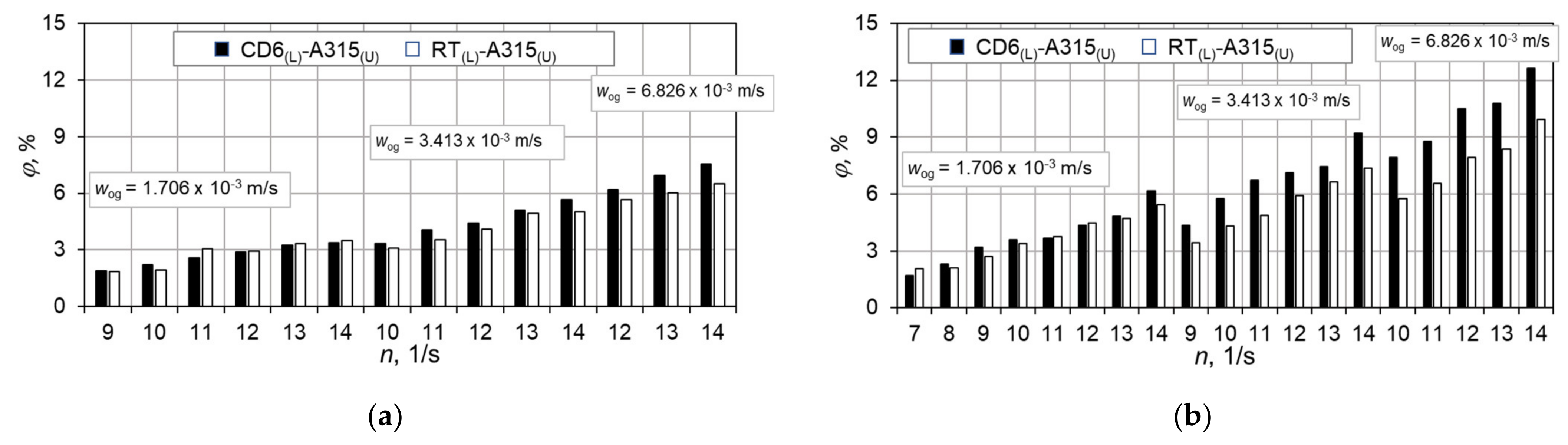
the type of the lower agitator (RT(L)-A315(U), CD6(L)-A315(U));
-
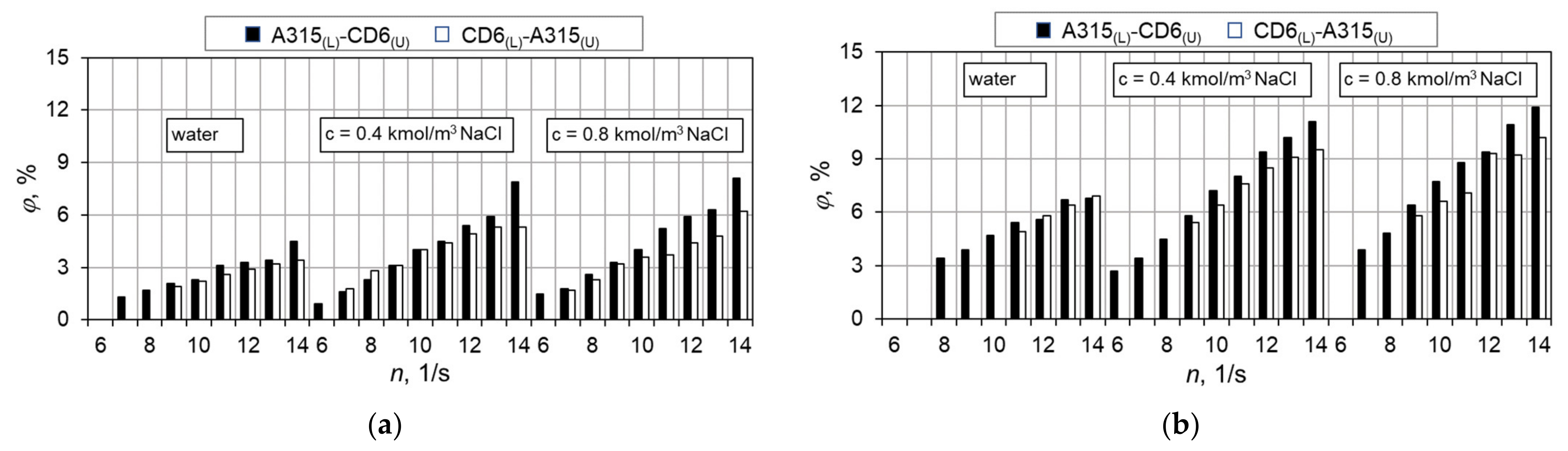
replacement of two impellers on the shaft (A315(L)-RT(U), RT(L)-A315(U) or A315(L)-CD6(U), CD6(L)-A315(U));
-
type of liquid in the system (distilled water, aqueous solutions NaCl of concentration c = 0.4 kmol/m3 and c = 0.8 kmol/m3, aqueous solution of sucrose of concentration c = 2.5% mass., 5% mass., 5% mass. aqueous solution of sucrose of concentration and yeast suspension concentration ys = 1% mass.);
-
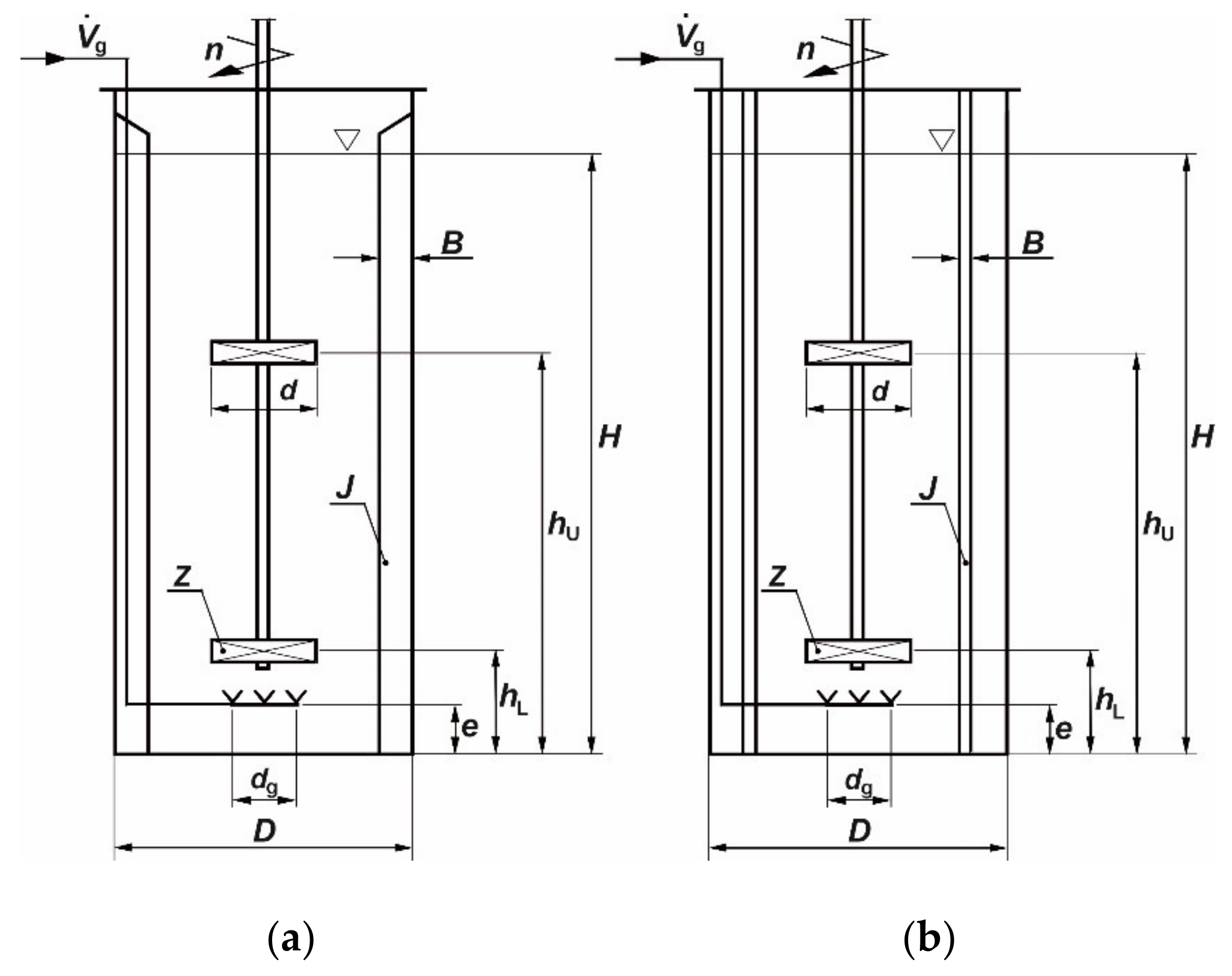
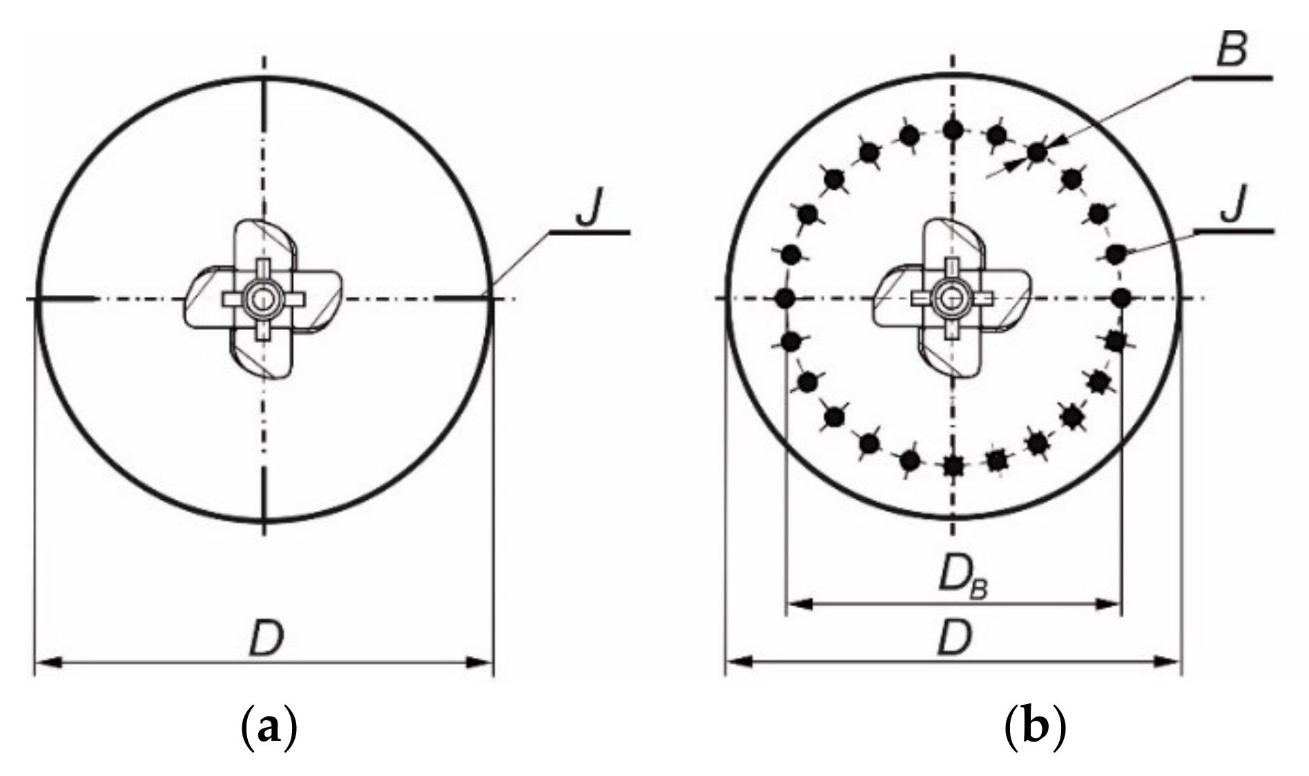
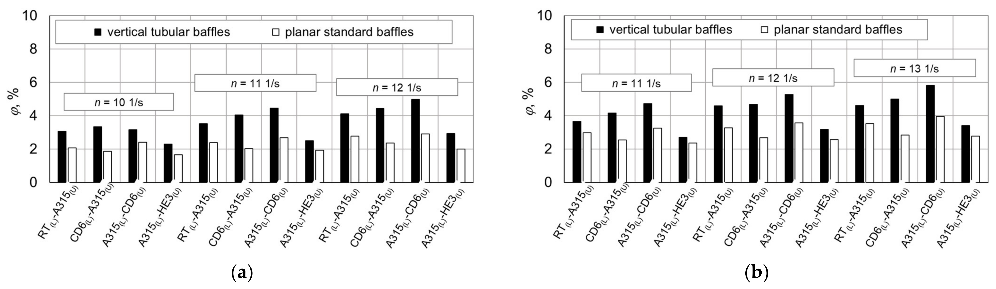
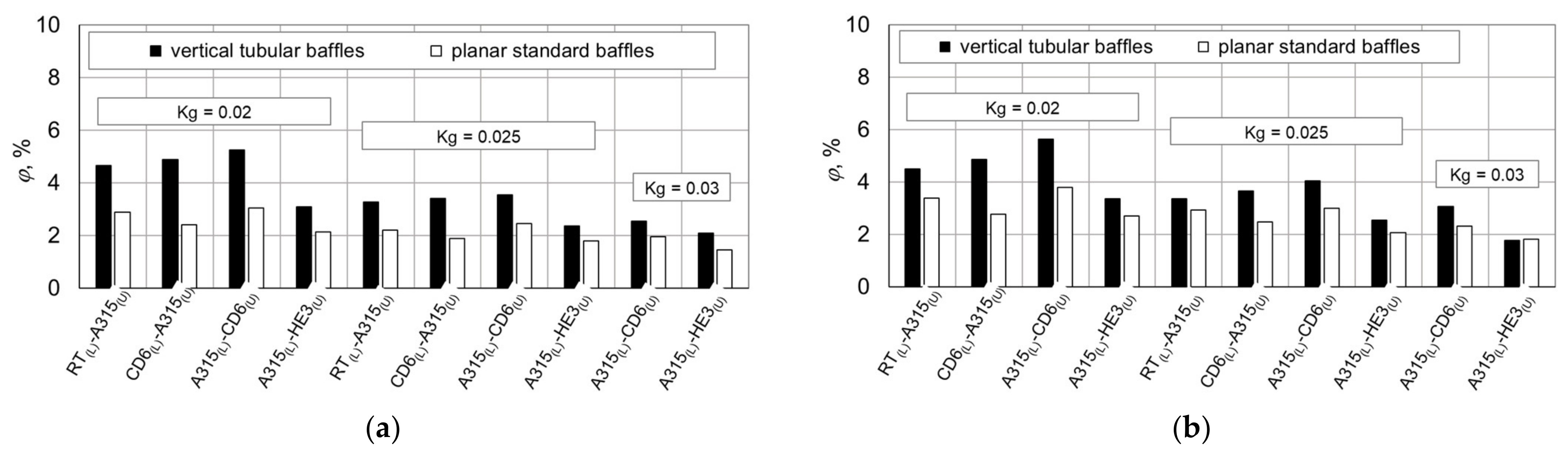
type of baffles (four planar standard baffles or 24 vertical tubular baffles) on gas hold-up.
In all the analyzed cases, it was found that gas hold-up increases with an increase in impeller speed and with an increase in superficial gas velocity in the vessel. Gas hold-up depends on the configuration of the impellers, the type of baffles and the type of liquid in the system.

3.1. Analysis of the Results Obtained in the Vessel with Planar Baffles

The results of the research on the influence of the selected parameters on the gas hold-up for a vessel with four standard baffles are shown in Figure 3, Figure 4 and Figure 5.
The effect of impellers configuration on gas hold-up, assuming a constant value of c = 2.5% mass., was presented in Figure 3. The influence of the upper impeller (Figure 3a) was analyzed on the basis of the results obtained for three impeller configurations, in which the A315 impeller was always installed as the lower impeller and the RT, CD 6 or HE3 impellers were installed as the upper impeller. On the basis of the obtained results, it was found that the highest values of gas hold-up, especially for the lower values of superficial gas velocity wog, were obtained for the vessel in which the RT impeller was installed as the upper one. Slightly lower results (by about 10–15% for the lowest superficial gas velocity) for gas hold-up were obtained for the vessel with the upper impeller CD6. The differences between the results obtained for the configuration of the A315(L)-RT(U) and A315(L)-CD6(U) decreased with an increase in impeller speed n and with an increase in superficial gas velocity wog. In the case of the highest value of superficial gas velocity wog, in some cases, the value of gas hold-up was comparable and even slightly higher for the A315(L)-CD6(U) impeller configuration. The replacement of the upper impeller producing radial–axial circulation of the liquid with impeller HE3, producing axial (axial–radial) circulation, resulted in a significant (approx. 70%) reduction in the value of gas hold-up. Comparing the results obtained for the configuration of the impellers, in which the upper impeller was the A315 impeller and the RT or CD6 impellers were mounted as the lower impeller, it was found that, in this case, also higher (even by about 20%; wog = 3.413 × 10⁻³ m/s) values of gas hold-up were obtained for the RT(L)-A315(U) impeller configuration (Figure 3b). The effect of the lower impeller on gas hold-up decreased with an increase in impeller speed and with an increase in the superficial gas velocity in the vessel. A comparison of the configuration of two impellers that differ in the location of individual impellers on the shaft (A315(L)-RT(U), RT(L)-A315(U) or A315(L)-CD6(U), CD6(L)-A315(U)) is shown in Figure 3c,d. In both cases, higher values of gas hold-up were obtained for the configuration in which the lower impeller was the A315 (for wog = 3.413 × 10⁻³ m/s; 5.973 × 10⁻³ m/s; 8.532 × 10⁻³ m/s, respectively, by about 30%; 20%; 7%—for the A315(L)-CD6(U) impeller configuration and about 25%; 17%; 7%—for the configuration of the A315(L)-RT(U) impellers). Detailed results of the influence of the selected parameters on gas hold-up for the configurations of the A315(L)-CD6(U) and CD6(L)-A315(U) impeller and the aqueous solution of sucrose system are presented in Cudak [28].
The effect of the type of liquid on gas hold-up for different configurations of the impellers was shown in Figure 4. Adding sucrose to the system increases the value of gas hold-up. The highest (more than two-fold) increase in the value of gas hold-up resulting from addition of sucrose to the system was found for the A315(L)-RT(U) impeller configuration (wog = 3.413 × 10⁻³ m/s). As the superficial gas velocity wog in the vessel increases, the effect of sucrose concentration decreases. For the highest value of superficial gas velocity (wog = 8.532 × 10⁻³ m/s), the gas hold-up increased by about 40–50% compared to the system without the addition of sucrose. Adding yeast suspension to the system negatively influences the value of gas hold-up. This may be due to the fact that the three-phase gas–biophase–liquid system has a limited ability to coalesce compared to other gas–liquid systems that show the ability to coalesce. In most cases, the addition of yeast to the system causes a decrease in the amount of gas hold-up by about 30%.
Assuming a constant value of gas flow number Kg, the value of gas hold-up with increasing sucrose concentration in the system increases on average by about 70% for wog = 5.973 × 10⁻³ m/s (Figure 5a) and about 50% for wog = 8.532 × 10⁻³ m/s (Figure 5b). On the other hand, adding yeast to the system caused a decrease in the amount of gas hold-up by about 25% regardless of the value of the superficial gas velocity in the vessel. In most cases, the highest values of gas hold-up, regardless of the type of system, were obtained for the configuration of the A315(L)-RT(U) impeller.
The effect of gas flow number Kg (= V ˙ g /(nd3), Weber number We (= n2d3ρ/σ), concentration of aqueous sucrose solution c, and concentration of yeast suspension ys on gas hold-up for gas–liquid and gas–biophase–liquid systems was developed as the relationship:
φ = C · Kg a · We b · 1 + c e · 1 + g · y s
The values of the coefficients (C, g) and exponents (a, b, e) and the average relative error of the equation are provided in Table 2.

3.2. Analysis of the Results Obtained in the Vessel with Vertical Tubular Baffles

The results of the research on the influence of the selected parameters on gas hold-up for a vessel with vertical tubular baffles were shown in Figure 6, Figure 7, Figure 8 and Figure 9. The influence of the type of upper impeller CD6 or HE3 when using a lower impeller of the A315 type on gas hold-up φ for different values of impeller speed and three different values of superficial gas velocity wog = 1.706 × 10⁻³ m/s, 3.413 × 10⁻³ m/s and 6.826 × 10⁻³ m/s is presented in Figure 6. Analyzing φ values obtained for a gas–liquid system where the liquid phase was water or aqueous solution of NaCl with a concentration c = 0.8 kmol/m3 and three different values wog, it has been stated that gas hold-up φ increases together with an increase in impeller speed n and with an increase in superficial gas velocity wog. In both presented (Figure 6) gas–liquid systems, higher values of gas hold-up φ were obtained when a Smith turbine (CD6) was used as the upper impeller. The circulation generated by the HE3 impeller used as the upper impeller affected obtaining lower φ values. For the air–water system (Figure 6a), the gas hold-up in liquid with wog = 1.706 × 10⁻³ m/s and n = 9 1/s increases by about 57% for the A315(L)-CD6(U) impeller configuration compared to the φ value obtained when the configuration A315(L)-HE3(U) impeller was used for mixing. Increasing the impeller speed from n = 9 1/s to n = 13 1/s with the constant superficial gas velocity wog = const = 1.706 × 10⁻³ m/s, the gas hold-up φ increases about 82%; if in the configuration impeller, the CD6 impeller was used as the upper impeller. Increasing the superficial gas velocity (wog = 3.413 × 10⁻³ m/s, wog = 6.826 × 10⁻³ m/s) for the analyzed values of impeller speed n, the tendency that higher values of φ were obtained when using the impeller system A315(L)-CD6(U) for mixing is maintained. For example, at wog = 6.826 × 10⁻³ m/s and n = 9 1/s, the higher value of about 48% φ has been obtained for the A315(L)-CD6(U) impeller configuration compared to the value of φ obtained for the same parameters wog and n for the A315(L)-HE3(U) impeller configuration. A significant influence of the upper impeller is visible for the gas–liquid system, where the liquid phase was the aqueous solution NaCl of concentration c = 0.8 kmol/m3 (Figure 6b). For the impeller speed n = 9 1/s and superficial gas velocity wog = 1.706 × 10⁻³ m/s, the φ value was obtained more than twice as high when a Smith impeller (CD6) was used as the upper impeller compared to the φ value obtained when an HE3 impeller was used as the upper impeller. For value of wog = 6.826 × 10⁻³ m/s and speed impeller n = 9 1/s, the φ value increases about 94% for the A315(L)-CD6(U) impeller configuration.
The influence of the type of lower impeller on the φ value was analyzed using the CD6(L)-A315(U) and RT(L)-A315(U) system impeller, where the Smith turbine (CD6) or Rushton turbine (RT) was used as the lower impeller. The dependence values φ = f(n) for two different impeller configurations CD6(L)-A315 (U) or RT(L)-A315(U) and for two different gas–liquid systems (air–water system, air–aqueous solution NaCl of concentration c = 0.8 kmol/m3) were presented in Figure 7. Comparing the φ values obtained for configuration of the CD6(L)-A315(U) impeller with the φ values obtained for configuration of the RT(L)-A315(U) for n = 13 1/s, the results were comparable at wog = 1.706 × 10⁻³ m/s, wog = 3.413 × 10⁻³ m/s and slightly, by about 15%, higher at wog = 6.826 × 10⁻³ m/s φ value for the air–water system. For the system air–aqueous solution NaCl of concentration c = 0.8 kmol/m3 for the constant superficial gas velocity wog = 1.706 × 10⁻³ m/s higher by about 11%, 18%, and 13%, the value of φ was obtained for the impeller speed n of n = 8 1/s, 9 1/s and 14 1/s, respectively, and the configuration of the CD6(L)-A315(U) impeller. For the increased superficial gas velocity wog = 3.413 × 10⁻³ m/s, wog = 6.826 × 10⁻³ m/s, respectively, higher values of φ by an average of about 26% for the analyzed range of impeller speed 9 1/s–14 1/s and about 32% for the range of impeller speed 10 1/s–14 1/s were obtained for the configuration of the CD6(L)-A315(U) impeller.
For three analyzed gas–liquid systems, such as air-distilled water and air–aqueous solution of NaCl of concentration c = 0.4 kmol/m3 and 0.8 kmol/m3, an influence of the type of liquid on the φ value was found (Figure 8). For a constant value of superficial gas velocity wog, lower values of φ were obtained for the air-distilled water system (the system is able to coalescence) than for the air–aqueous solution of NaCl (the system of lower ability to coalescence). Comparing the obtained φ values for the air–aqueous solution NaCl of concentration c = 0.4 kmol/m3 and 0.8 kmol/m3, it was found that the change in concentration did not significantly affect the φ value.
The effect of gas flow number Kg, Weber number We and Y parameter on the gas hold-up, for gas–liquid systems, was developed as the relationship:
φ = C · Kg a · We b · Y d
The values of coefficient C and exponents a, b and d, the average relative error and range of number of gas flow Kg (= V ˙ g /(nd3), number of Weber We (= n2d3ρ/σ) and parameter Y have been presented in Table 3.
The measured values of φ for the vessel with vertical tubular baffles and configuration of two impellers A315(L)-CD6(U) and CD6(L)-A315(U) for two different superficial gas velocity wog = const = 1.706 × 10⁻³ m/s and 5.119 × 10⁻³ m/s are compared in Figure 9. Analyzing the values of φ obtained for three liquid–gas systems (air-distilled water and air–aqueous solution of NaCl of concentration c = 0.4 kmol/m3 and 0.8 kmol/m3) and two impellers configuration, it was found that, for the constant superficial gas velocity wog = const = 1.706 × 10⁻³ m/s and 5.119 × 10⁻³ m/s, gas hold-up φ increases with an increase in the speed impeller n. Placing the A315 impeller in the lower position of the A315(L)-CD6(U) impeller configuration and the CD6 in the upper impeller position increases the operating range of this system. In this geometry, good gas dispersion starts at lower values of n compared to the CD6(L)-A315(U) impeller. It was observed in Figure 9a that, when using the A315(L)-CD6(U) impeller configuration and wog = 1.706 × 10⁻³ m/s for the three gas–liquid systems, the φ values are on average higher by about 18%. Only in a few cases, for the speed impeller n = 7 1/s and 8 1/s and the superficial gas velocity wog = const = 1.706 × 10⁻³ m/s and the air–aqueous solution of NaCl of concentration c = 0.4 kmol/m3, as shown in Figure 9a, the values of φ are, respectively, 12% and 22% higher when the CD6(L)-A315(U) configuration was used. Analyzing the data of φ values presented in Figure 9b for three different liquid–gas systems and the value of the superficial gas velocity wog = 5.119 × 10⁻³ m/s, higher values of φ were obtained for the A315(L)-CD6(U) impeller configuration. Only when the superficial gas velocity is wog = 5.119 × 10⁻³ m/s and the speed impeller n is equal to 12 1/s and 14 1/s, the values of φ for the gas-distilled water system and for the impeller configuration CD6(L)-A315(U) are slightly higher (on average by about 2%).

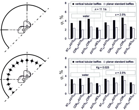
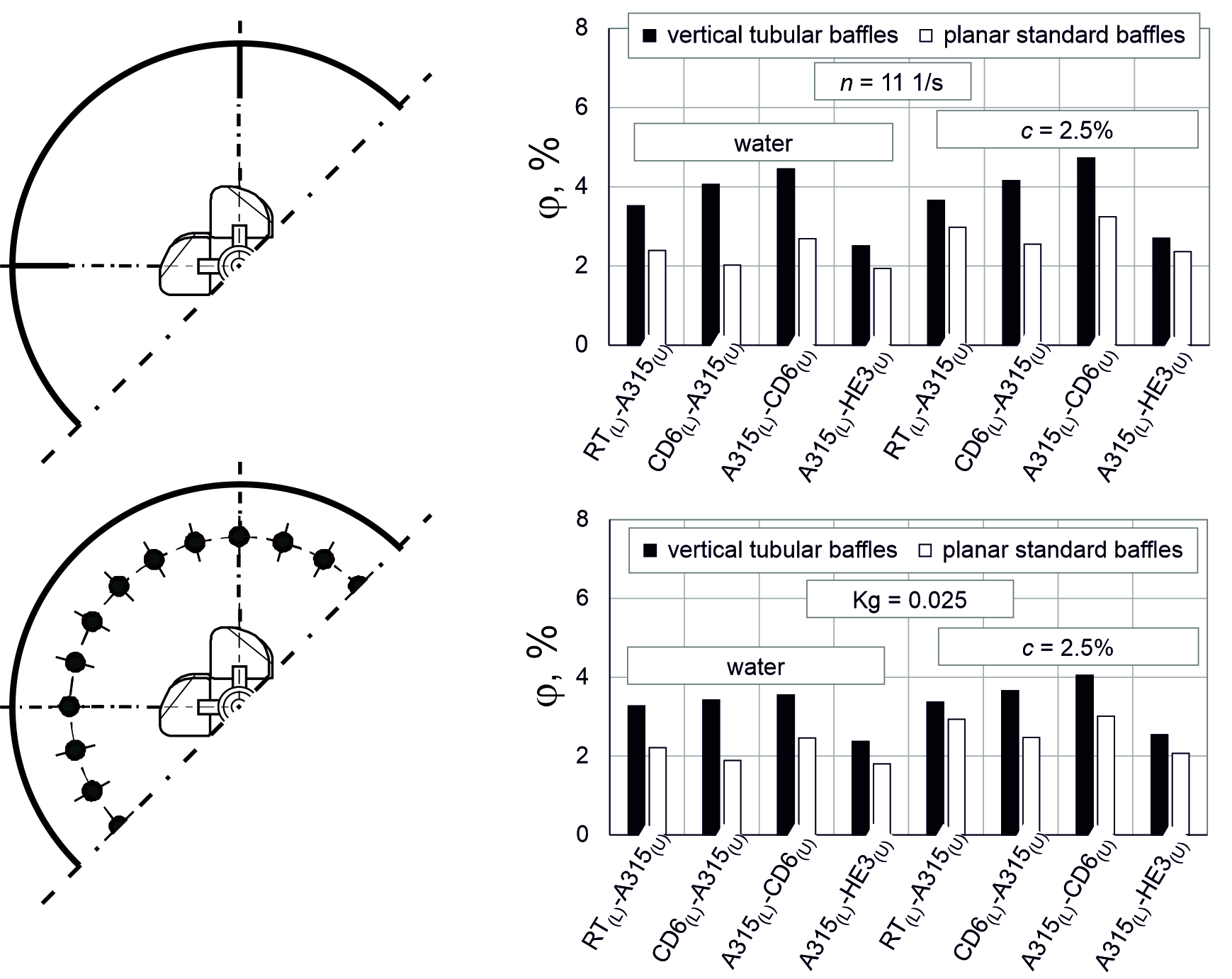
3.3. Comparison of the Results Obtained in the Vessels with Planar Baffles and Vertical Tubular Baffles

The obtained critical impellers speed, at which it was assumed that the system has good mixing and phase dispersion, depend not only on the configuration of the impellers but also on the type of baffles in the vessel (Figure 10). In the case when the vessel was fitted with vertical tubular baffles, lower (by about 30%) values of the critical impeller speed were obtained for the impellers configuration in which the A315 impeller was mounted on the bottom shaft. The location of the A315 impeller in the upper position resulted in lower critical values of the impeller speed (by about 15–20%) in the case when planar standard baffles were installed in the vessel.
In all the analyzed cases, assuming constant values of superficial gas velocity wog and impeller speed n, it was found that significantly (even twice) higher values of gas hold-up were obtained for the vessel with vertical tubular baffles (Figure 11). The influence of the baffles on gas hold-up depends on the type of configuration of the impellers and the type of liquid in the system. Comparing the results obtained in the vessel with vertical tubular baffles to the tank with planar standard baffles, it was found that the greatest effect on the values of gas hold-up was obtained for the configuration of the CD6(L)-A315(U) impellers. For this configuration of impellers for the vessel with vertical tubular baffles, the results for the water–air system were up to two times higher and, for the 2.5% aqueous sucrose-air system, about 70% higher compared to the vessel with planar standard baffles. The influence of the type of baffles on gas hold-up, for all the analyzed impellers configurations, decreased when sucrose was added to the vessel. On the other hand, when comparing the results obtained for the tested vessel–impeller configuration–baffle systems, it was found that, assuming a constant value of gas flow number Kg, the effect of baffles type decreases not only with an increase in the sucrose concentration in the system but also with an increase in the gas flow number Kg (Figure 12).

4. Conclusions

Based on the experimental studies conducted, it was found that:
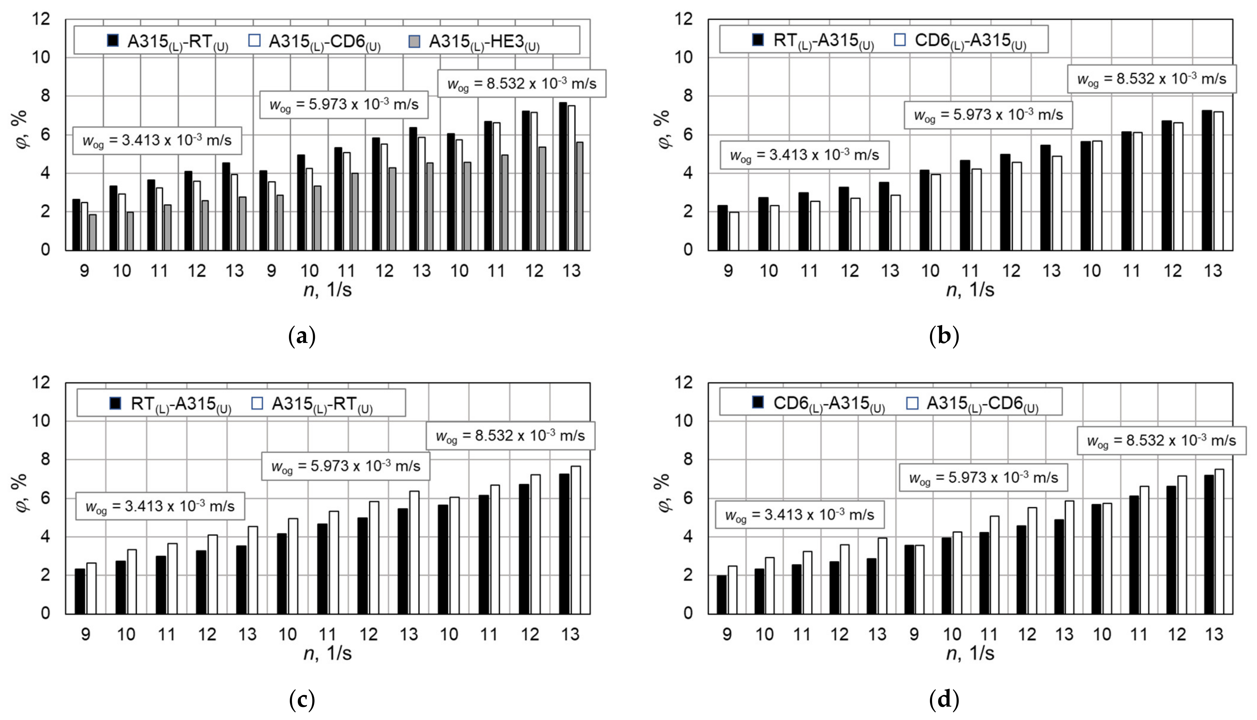
  • For all tank–baffle–impeller configurations, gas hold-up φ increases with an increase in impeller speed and with an increase in the superficial gas velocity in the vessel. The influence of impeller speed and superficial gas velocity in the vessel on the value of gas hold-up φ depends on the configurations of the impeller, the type of baffles and the type of liquid in the system.
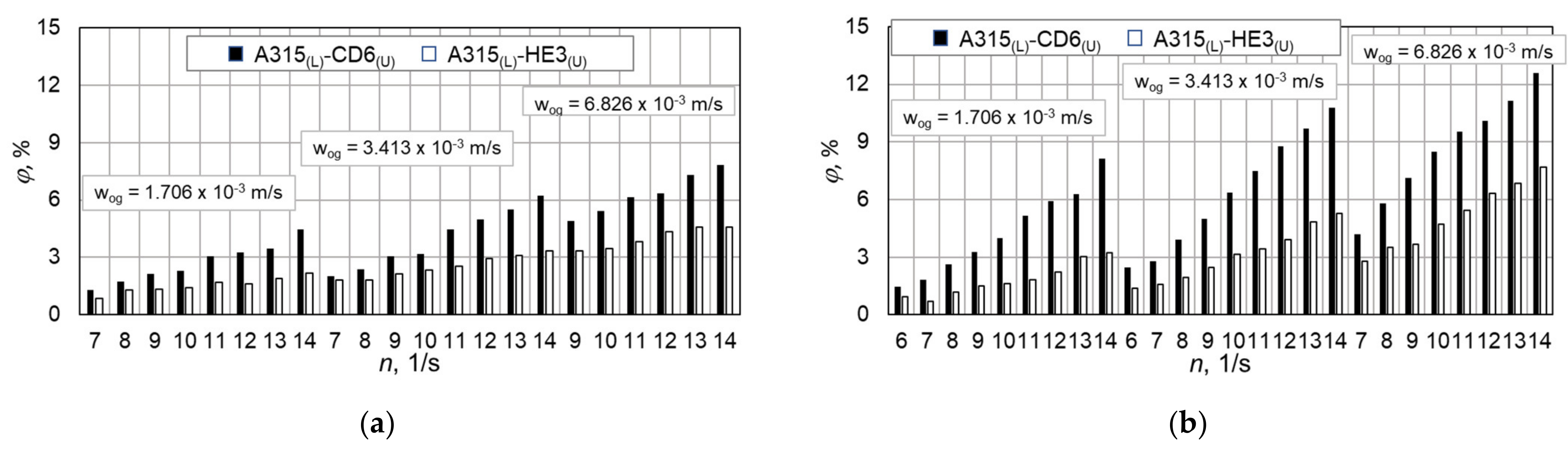
  • Regardless of the type of baffles used in the tests, higher values of φ were obtained when the A315 impeller was installed on the lower shaft. In this case, higher values of gas hold-up φ, both for the vessels with planar or vertical tubular baffles, were obtained when the upper shaft was equipped with an impeller generating radial–axial circulation (RT or CD6) compared to the values of φ obtained when the upper impeller used was an HE3 impeller.
  • The influence of the lower impeller on gas hold-up decreased with an increase in superficial gas velocity in the vessel with four planar baffles. The opposite tendency could be noticed in the case when 24 vertical tubular baffles were installed in the vessel. Then, they increased differently between the tested systems with an increase in superficial gas velocity in the vessel.
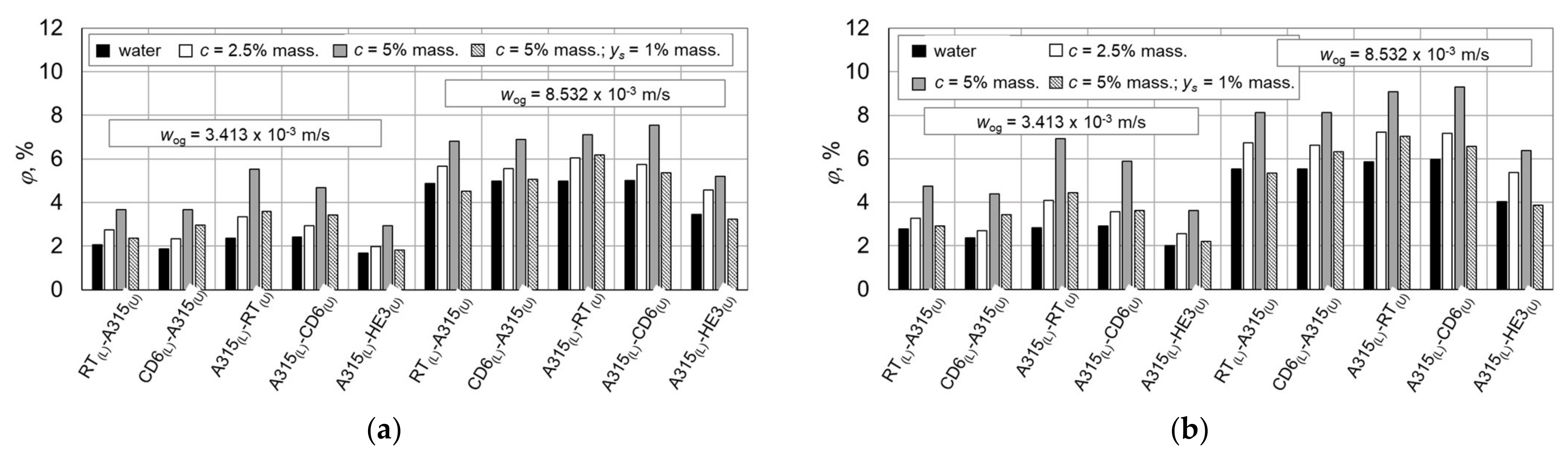
  • Adding electrolytes or sucrose to the water–air system increases the value of gas hold-up φ. On the other hand, when yeast suspension was added to the system of aqueous sucrose solution with air, the value of φ decreased. The rheological properties of the fluid may affect the reduction in gas hold-up values for a three-phase system compared to two-phase systems. In the analyzed two-phase systems, the liquids occurring in them can be classified as Newtonian liquids, whereas the three-phase system in which yeast was added to the aqueous sucrose solution showed the properties of a non-Newtonian fluid.
  • Comparing the values of critical impellers speed for both tank–baffle configurations, it was found that good dispersion was obtained faster for the system with 24 vertical tubular baffles when the A315 impeller was installed as the lower impeller. In the situation when the A315 impeller was mounted in the upper position, good dispersion was obtained when four planar baffles were installed in the vessel.
  • In all the analyzed cases, assuming stability of other parameters, higher values of gas hold-up were obtained for the vessel with 24 vertical tubular baffles compared to the vessel with four planar standard baffles.

Author Contributions

Conceptualization, M.M.-G. and M.C.; methodology, M.M.-G. and M.C.; software, M.M.-G. and M.C.; validation, M.M.-G. and M.C.; formal analysis, M.M.-G. and M.C.; investigation, M.M.-G. and M.C.; resources, M.M.-G. and M.C.; data curation, M.M.-G. and M.C.; writing—original draft preparation, M.M.-G. and M.C.; writing—review and editing, M.M.-G. and M.C.; visualization, M.M.-G. and M.C.; supervision, M.M.-G. and M.C. All authors have read and agreed to the published version of the manuscript.

Funding

This research received no external funding.

Data Availability Statement

The data presented in this study are available on request from the corresponding author (M.C.).

Conflicts of Interest

The authors declare no conflict of interest.

Nomenclature

alength of the impeller blade [m]
Bwidth of the baffle [m]
bwidth of the impeller blade [m]
cconcentration [% mass., kmol/m3]
Dinner diameter of the vessel [m]
DBdiameter of the tubular coil (baffles) [m]
ddiameter of the impeller [m]
dgsparger diameter [m]
doholes on the sparger [m]
eoff-bottom clearance of gas sparger [m]
factivity
Hliquid height in the vessel [m]
hLdistance between lower impeller and bottom of the vessel [m]
hUdistance between upper impeller and bottom of the vessel [m]
hg−Lheight of a gas–liquid mixture in the vessel [m]
inumber of holes on the ring sparger
Jnumber of baffles
nimpeller speed [1/s]
Rgas constant, J/molK
rradius of curvature of the impeller blade
Ttemperature [K]
V ˙ g gas flow rate [m3/s]
wogsuperficial gas velocity, = 4 V ˙ g π D 2 [m/s]
Yparameter
ysyeast concentration [% mass.]
Znumber of impeller blades
Greek symbols
βpitch of the impeller blade [deg]
μdynamic viscosity of the liquid [Pas]
φgas hold-up
ρdensity of the liquid [kg/m3]
σsurface tension [N/m]
Subscripts
grefers to gas phase
lrefers to liquid phase
Lrefers to lower impeller
Urefers to upper impeller

References

  1. Stręk, F. Agitation and Agitated Vessels; WNT: Warszawa, Poland, 1981. (In Polish) [Google Scholar]
  2. Kamieński, J. Agitation of Multiphase Systems; WNT: Warszawa, Poland, 2004. (In Polish) [Google Scholar]
  3. Chinnasamy, G.; Kaliannan, S.; Eldho, A.; Nadarajan, D. Development and performance analysis of a novel agitated vessel. Korean J. Chem. Eng. 2016, 33, 1181–1185. [Google Scholar] [CrossRef]
  4. Khalili, F.; Nasr, M.R.J.; Kazemzadeh, A.; Ein-Mozaffari, F. Analysis of gas holdup and bubble behavior in a biopolymer solution inside a bioreactor using tomography and dynamic gas disengagement techniques. J. Chem. Technol. Biotechnol. 2018, 93, 340–349. [Google Scholar] [CrossRef]
  5. Liu, B.; Zheng, Y.; Cheng, R.; Xu, Z.; Wang, M.; Jin, Z. Experimental study on gas-liquid dispersion and mass transfer in shear-thinning system with coaxial mixer. Chin. J. Chem. Eng. 2018, 26, 1785–1791. [Google Scholar] [CrossRef]
  6. Major-Godlewska, M.; Radecki, D. Experimental analysis of gas hold-up for gas-liquid system agitated in a vessel equipped with two impellers and vertical tubular baffles. Pol. J. Chem. Technol. 2018, 20, 7–12. [Google Scholar] [CrossRef] [Green Version]
  7. Cudak, M. The effect of vessel scale on gas hold-up in gas-liquid systems. Chem. Process Eng. 2020, 41, 241–256. [Google Scholar] [CrossRef]
  8. Barros, P.A.; Ein-Mozaffari, F.; Lohi, A. Gas Dispersion in Non-Newtonian Fluid with Mechanically Agitated Systems: A review. Processes 2022, 10, 275. [Google Scholar] [CrossRef]
  9. Major-Godlewska, M.; Karcz, J. Process characteristics for a gas-liquid system agitated in a vessel equipped with a turbine impeller and tubular baffles. Chem. Pap. 2011, 65, 132–138. [Google Scholar] [CrossRef]
  10. Major-Godlewska, M.; Karcz, J. Agitation of a gas–solid–liquid system in a vessel with high-speed impeller and vertical tubular coil. Chem. Pap. 2012, 66, 566–573. [Google Scholar] [CrossRef]
  11. Kiełbus-Rąpała, A.; Karcz, J. Experimental analysis of the hydrodynamics of a three-phase system in a vessel with two impellers. Chem. Pap. 2012, 66, 574–582. [Google Scholar] [CrossRef]
  12. Jamshed, A.; Cooke, M.; Ren, Z.; Rodgers, T.L. Gas–liquid mixing in dual agitated vessels in the heterogeneous regime. Chem. Eng. Res. Des. 2018, 133, 55–69. [Google Scholar] [CrossRef]
  13. de Jesus, S.S.; Moreira Neto, J.; Filho, R.M. Hydrodynamics and mass transfer in bubble column, conventional airlift, stirred airlift and stirred tank bioreactors, using viscous fluid: A comparative study. Biochem. Eng. J. 2017, 118, 70–81. [Google Scholar] [CrossRef]
  14. Cudak, M. Hydrodynamic characteristics of mechanically agitated air-aqueous sucrose solutions. Chem. Process Eng. 2014, 35, 97–107. [Google Scholar] [CrossRef] [Green Version]
  15. Jamshidzadeh, M.; Ein-Mozaffari, F.; Lohi, A. Local and overall gas holdup in an aerated coaxial mixing system containing a non-Newtonian fluid. AIChE J. 2020, 66, e17016. [Google Scholar] [CrossRef]
  16. Saravanan, K.; Ramamurthy, V.; Chandramohan, K. Gas hold-up in multiple impeller agitated vessels. Mod. Appl. Sci. 2009, 3, 49–59. [Google Scholar] [CrossRef] [Green Version]
  17. Karcz, J.; Szoplik, J.; Major-Godlewska, M.; Cudak, M.; Kiełbus-Rąpała, A. Agitation efficiency of different physical systems. Chem. Process Eng. 2021, 41, 139–156. [Google Scholar] [CrossRef]
  18. Busciglio, A.; Grisafi, F.; Scargiali, F.; Brucata, A. On the measurement of local gas hold-up, interfacial area and bubble size distribution in gas-liquid contactors via light sheet and image analysis: Imaging technique and experimental results. Chem. Eng. Sci. 2013, 102, 551–566. [Google Scholar] [CrossRef]
  19. Wan, X.; Takahata, Y.; Takahashi, K. Power consumption and gas-liquid dispersion in turbulently agitated vessels with vertical dual-array tubular coil baffle. Chem. Pap. 2016, 70, 445–453. [Google Scholar] [CrossRef]
  20. Wan, X.; Takahata, Y.; Takahashi, K. Power consumption, gas holdup, and mass-transfer coefficient of triple-impeller configurations in a stirred vessels with vertical tubular coils. Can. J. Chem. Eng. 2016, 94, 349–354. [Google Scholar] [CrossRef]
  21. Petricek, R.; Moucha, T.; Rejl, F.J.; Valenz, L.; Haidl, J.; Cmelikova, T. Volumetric mass transfer coefficient, power input and gas hold-up in viscous liquid in mechanically agitated fermenters. Measurements and scale-up. Int. J. Heat Mass Transf. 2018, 124, 1117–1135. [Google Scholar] [CrossRef]
  22. Amiraftabi, M.; Khiadani, M.; Mohammed, H.A. Performance of a dual helical ribbon impeller in a two-phase (gas-liquid) stirred tank reactor. Chem. Eng. Process. Process Intensif. 2020, 148, 107811. [Google Scholar] [CrossRef]
  23. Liu, B.; Xiao, Q.; Gao, P.; Sunder, B.; Fan, F. Investigation of gas–liquid dispersion and mass transfer performance of wide-viscosity-range impellers in water solutions of xanthan gum. Chem. Eng. Res. Des. 2020, 154, 60–69. [Google Scholar] [CrossRef]
  24. Bao, Y.; Yang, J.; Wang, B.; Gao, Z. Influence of impeller diameter on local gas dispersion properties in a sparged multi-impeller stirred tank. Chin. J. Chem. Eng. 2015, 23, 615–622. [Google Scholar] [CrossRef]
  25. Busciglio, A.; Opletal, M.; Moucha, T.; Montante, G.; Paglianti, A. Measurement of gas hold-up distribution in stirred vessels equipped with pitched blade turbines by means of Electrical Resistance Tomography. Chem. Eng. Trans. 2017, 57, 1273–1278. [Google Scholar] [CrossRef]
  26. Machoň, V.; Vlček, J.; Kudrna, V. Gas hold-up in agitated aqueous solutions of strong inorganic salts. Collect. Czechoslov. Chem. Commun. 1978, 43, 593–603. [Google Scholar] [CrossRef]
  27. Lee, J.C.; Meyrick, D.L. Gas–Liquid interfacial areas in salt solutions in an agitated tank. Trans. Inst. Chem. Eng. 1970, 48, 37–45. [Google Scholar]
  28. Cudak, M. The gas hold-up for the gas-liquid system in a vessel with two impellers. Inż. Ap. Chem. 2018, 57, 93–94. (In Polish) [Google Scholar]
Figure 1. Geometrical parameters of the vessel with: (a) four planar standard baffles; (b) 24 vertical tubular baffles located on the circuit.
Energies 15 08685 g001
Figure 2. Located baffles inside vessel; (a) four planar standard baffles; (b) 24 vertical tubular baffles located on the circuit.
Energies 15 08685 g002
Figure 3. Dependence of φ = f(n) for different configurations of impeller; standard planer baffles, c = 2.5% mass. (a) the effect of the upper impeller type; (b) the effect of the lower impeller type; (c,d) the effect of replacement of two impellers on the shaft.
Energies 15 08685 g003
Figure 4. Dependence of φ = f(configurations of impeller); standard planer baffles, (a) n = 10 1/s; (b) n = 12 1/s.
Energies 15 08685 g004
Figure 5. Dependence of φ = f(configurations of impeller); standard planer baffles, (a) wog = 5.973 × 10⁻³ m/s; (b) wog = 8.532 × 10⁻³ m/s.
Energies 15 08685 g005
Figure 6. Dependence of φ = f(n) for two different impeller configurations A315(L)-CD6(U) or A315(L)-HE3(U) and for two different gas–liquid systems: (a) air–water system, (b) air–aqueous solution NaCl of concentration c = 0.8 kmol/m3.
Energies 15 08685 g006
Figure 7. Dependence of φ = f(n) for two different impeller configurations CD6(L)-A315 (U) or RT(L)-A315(U) and for two different gas–liquid systems: (a) air–water system, (b) air–aqueous solution NaCl of concentration c = 0.8 kmol/m3.
Energies 15 08685 g007
Figure 8. The distribution of gas hold-up as a function of a number of gas flow Kg for different superficial gas velocity wog: 1—wog = 1.706 × 10⁻³ m/s, 2—wog = 3.413 × 10⁻³ m/s, 3—wog = 5.119 × 10⁻³ m/s, 4—wog = 6.826 × 10⁻³ m/s.
Energies 15 08685 g008
Figure 9. Dependence of φ = f(n) for two different impeller configurations A315(L)-CD6(U) or CD6(L)-A315(U) and for three different gas–liquid systems for superficial gas velocity wog: (a) 1.706 × 10⁻³ m/s, (b) 5.119 × 10⁻³ m/s.
Energies 15 08685 g009
Figure 10. Dependence of ncr = f(configurations of impeller); wog = 3.413 × 10⁻³ m/s.
Energies 15 08685 g010
Figure 11. Dependence of φ = f(configuration of impellers), for different n; wog = 3.413 × 10⁻³ m/s; (a) water; (b) aqueous sucrose solution c = 2.5% mass.
Energies 15 08685 g011
Figure 12. Dependence of φ = f(configuration of impellers), for different Kg; wog = 3.413 × 10⁻³ m/s; (a) water; (b) aqueous sucrose solution c = 2.5% mass.
Energies 15 08685 g012
Table 1. Geometrical parameters of impellers.
No.Impellera/db/dZβr
1.Rushton turbine (RT)0.250.26-
2.Smith turbine (CD6)0.250.26 b/2
3.A315-0.34445
4.HE3-0.2330
Table 2. Values of coefficients C, g and exponents a, b and e in Equation (5), the average relative error and ranges of gas flow number Kg, Weber number We.
Impeller ConfigurationCabeg±Δ, %Range
A315(L)-CD6(U)3.44 × 10−40.630.9310.84−13.107Kg ∈ <1.94 × 10⁻²–7.20 × 10⁻²>
We ∈ <653–2117>
CD6(L)-A315(U) 7.62 × 10−40.820.899.64−7.936Kg ∈ <1.94 × 10⁻²–7.78 × 10⁻²>
We ∈ <600–2117>
RT(L)-A315(U)7.64 × 10−40.720.859.59−24.685Kg ∈ <1.99 × 10⁻²–6.48 × 10⁻²>
We ∈ <709–2112>
A315(L)-RT(u)4.47 × 10−40.490.8411.70−17.988Kg ∈ <1.99 × 10⁻²–7.20 × 10⁻²>
We ∈ <500–2117>
A315(L)-HE3(U)3.69 × 10−40.660.8910.39−4.558Kg ∈ <1.94 × 10⁻²–6.94 × 10⁻²>
We ∈ <767–2117>
Table 3. Values of coefficient C and exponents a, b and d in Equation (6), the average relative error and ranges of the number of gas flow Kg, number of Weber We and parameter Y.
Impeller
Configuration
Cabd±Δ, %RangeGas–Liquid System
A315(L)-CD6(u)1.7 × 10−40.40.971110%Kg ∈ <8,84 × 10⁻³–64.8 × 10⁻³>;
We ∈ <476–2551>; Y = 1
Air–Water
Kg ∈ <8.84 × 10⁻³–70.69 × 10⁻³>;
We ∈ <428–2556>; Y = 1.36
Air–NaCl c = 0.4 kmol/m3
Kg ∈ <8.84 × 10⁻³–77.76 × 10⁻³>;
We ∈ <431–2577>; Y = 1.6
Air–NaCl c = 0.8 kmol/m3
CD6(L)-A315(U) 4.35 × 10−40.5330.90.958%Kg ∈ <8.84 × 10⁻³–44.43 × 10⁻³>;
We ∈ <896–2566>; Y = 1
Air–Water
Kg ∈ <8.84 × 10⁻³–53.63 × 10⁻³>;
We ∈ <584–2563>; Y = 1.36
Air–NaCl c = 0.4 kmol/m3
Kg ∈ <8.84 × 10⁻³–51.84 × 10⁻³>;
We ∈ <589-2584>; Y = 1.6
Air–NaCl c = 0.8 kmol/m3
RT(L)-A315(U)1.64 × 10−40.4260.9580.86%Kg ∈ <8.84 × 10⁻³–44.43 × 10⁻³>;
We ∈ <899–2574>; Y = 1
Air–Water
Kg ∈ <8.84 × 10⁻³–51.84 × 10⁻³>;
We ∈<585–2567>; Y = 1.36
Air–NaCl c = 0.4 kmol/m3
Kg ∈ <8.84 × 10⁻³–51.84 × 10⁻³>;
We ∈ <589–2586>; Y = 1.6
Air–NaCl c = 0.8 kmol/m3
A315(L)-HE3(U)1.22 × 10−40.6221.0530.79610%Kg ∈ <8.84 × 10⁻³–62.2 × 10⁻³>;
We ∈ <430–2567>; Y = 1
Air–Water
Kg ∈ <8.84 × 10⁻³–74 × 10−3>;
We ∈ <338–2559>; Y = 1.36
Air–NaCl c = 0.4 kmol/m3
Kg ∈ <8.84 × 10⁻³–74 × 10−3>;
We ∈ <341–2578>; Y = 1.6
Air–NaCl c = 0.8 kmol/m3
Publisher’s Note: MDPI stays neutral with regard to jurisdictional claims in published maps and institutional affiliations.

