Article

Study on Stability and Control of Surrounding Rock in the Stopping Space with Fully Mechanized Top Coal Caving under Goaf

1
School of Energy & Mining Engineering, China University of Mining & Technology (Beijing), Beijing 100083, China
2
Beijing Key Laboratory for Precise Mining of Intergrown Energy and Resources, China University of Mining & Technology (Beijing), Beijing 100083, China
3
Jinneng Holding Group, Datong 037000, China
*
Author to whom correspondence should be addressed.
Energies 2022, 15(22), 8498; https://doi.org/10.3390/en15228498
Submission received: 12 October 2022 / Revised: 7 November 2022 / Accepted: 10 November 2022 / Published: 14 November 2022
(This article belongs to the Special Issue Method and Technology of Green Coal Mining)

Abstract

:
Under the condition of fully mechanized top coal caving in close-distance coal seams, the surrounding rock of the stopping space easily loses stability during the withdrawal of mining equipment in the working face because the lower coal seam working face is located under the goaf and the overburden rock has a large range of complex interaction. Field investigation, theoretical analysis, laboratory experiment, similar simulation experiment, numerical simulation, and field industrial tests are used to carry out the research on the stability and control of the surrounding rock in the large section stopping space under the goaf in this paper. The research conclusions are as follows. (1) It is determined that the lower coal seam working face can only stop mining under the goaf, and the reasonable stopping position under the goaf should ensure that the key block fracture line of the main roof is behind the support. (2) The interaction law between the main roof’s key blocks of the upper and lower coal seams is analyzed, and the catastrophic conditions for sliding instability and rotary instability of the main roof’s key blocks of the upper and lower coal seams are obtained. (3) “Anchorage with push and pull equipment-Embedded anchorages and trays” integral anchoring technology is developed. The dimensions of the push and pull equipment are determined. (4) Through numerical simulation of the distribution characteristics of the anchor cable pre-stress field, the asymmetric control scheme of “Partition long and short anchor cables + Integral polyurethane mesh + Embedded anchorages and trays for roof protection” is determined. The rock pressure observation shows that the withdrawal of the working face equipment is implemented safely.

1. Introduction

The coal seam group is the main occurrence condition of coal seams in China, and the mining of close-distance coal seams is one of the main problems faced by coal mining enterprises in China [1,2]. Thick coal seam reserves account for approximately 45% of all coal reserves in China. The mining of thick coal seams is the main part of coal mining in China, and fully mechanized top coal caving is the first choice for thick seam mining [3,4,5]. After the mining of the working face is completed, the retracement channel is reserved in order to facilitate the rapid withdrawal of hydraulic supports, shearers, and other equipment [6]. At present, equipment withdrawal is performed in mainly two ways: pre-driven retraction channel and non-pre-driven retraction channel [7]. It is not simple to control the deformation of surrounding rock under the influence of advance abutment pressure of the working face with pre-driven retracement channels [8]. In contrast, a non-pre-driven retraction channel can avoid the strong incoming pressure and can be set up flexibly, which has a better application value [9,10]. During the retraction of the equipment of the working face, a large section stopping space is constitutive of the retraction channel and the supporting area of supports. The stability of the surrounding rock in the stopping space guarantees the efficient and safe retraction of the equipment [11]. Many scholars have conducted research on the stability and control of the surrounding rock in the stopping space. Yang et al. [12] studied the influence of the main roof rupture position and overburden structure on the stability of surrounding rock in the stopping space in order to achieve the safe retraction of equipment at the working face of soft coal seams and proposed a differentiated support scheme for the roof and lane gang of retraction channels. In view of the complex fault structure and the difficulty of roof management during the late mining period of the working face, Song [13] selected a reasonable position of the stopping line through the study of roof transport law and analysis of mine pressure measurements. Through numerical simulation, Chen et al. [14] concluded that there are four different damage zones around the stopping space, namely the shear damage zone, tensile damage zone, partial elasticity zone, and plastic damage zone, and adopted various measures such as optimizing the position of the stopping line, reducing the width of the stopping section, and increasing the number of anchor cables to ensure the stability of the surrounding rock in the stopping space. Wu et al. [15] proposed a rapid withdrawal technology for non-pre-driven retraction channels in heavily mechanized top-coal caving faces by studying the law of mine pressure appearing on the working face and the reasonable position of stopping lines for the problem of crushed pre-driven retraction channels. Liu et al. [16] analyzed the most dangerous rupture patterns of the immediate roof and main roof in the stopping space in view of roof-fall accidents and withdrawal accidents in the deep stop mining space. The study showed that the immediate roof presented showed a zonal progressive rupture pattern under strong loads, and the main roof formed a lateral rotation structure with the retraction of the support and triggered the instability of the support. Wang et al. [17] analyzed the position of the stopping line and the key block of the main roof to investigate the stability of the surrounding rock of the retraction channel using UDEC numerical simulation software and clarified the reasonable position relationship between the stopping line and the key block of the main roof.
The above research is of great significance to ensure the stability of surrounding rock in the stopping space and the efficient withdrawal of equipment, but they are all concentrated on the condition of a single coal seam with fully mechanized mining. There are few studies on the stability of surrounding rock in the stopping space under the condition of fully mechanized top coal caving in close-distance seams. Under the condition of close-distance coal seam mining, if the upper coal seam is not mined, the stopping space of the lower coal seam is located under the solid coal, and its ground pressure law and surrounding rock control are not different from that of single coal seam mining, as shown in Figure 1. If the upper coal seam has been mined, the stopping space of the lower coal seam is located under the goaf. As shown in Figure 2, the ground pressure is relatively severe due to the influence of the large-scale joint movement of overburden, and the stopping space is difficult to control. [18,19,20,21,22] The top coal above the stopping space of the fully mechanized top coal caving face is easily broken. It is difficult to push the anchoring agent when using the anchor cable support, and the anchor cable anchorage in the stopping space is generally exposed. During the last mining and hanging of the net, the anchorage will be damaged when moving the support. This causes the failure of the support components and brings difficulties to the surrounding rock control [23,24,25].
Based on the above discussion, it is necessary to study the stability and control of the surrounding rock in the large section stopping space under the goaf with fully mechanized top coal caving. By means of field investigation, theoretical analysis, laboratory experiment, similar simulation experiment, numerical simulation, and industrial field tests, this paper clarifies that the stopping space of the lower coal seam can only be located under the goaf. The reasonable stopping position under the goaf should ensure that the fracture line of the main roof’s key block is behind the support. The catastrophic conditions for sliding instability and rotary instability of the main roof‘s key blocks of upper and lower coal seams are obtained. The integral anchoring technology of “Anchorage with push and pull equipment + embedded anchorages and trays” is developed. The asymmetric control scheme of surrounding rock in the stopping space is proposed, and the industrial field test is finally carried out.

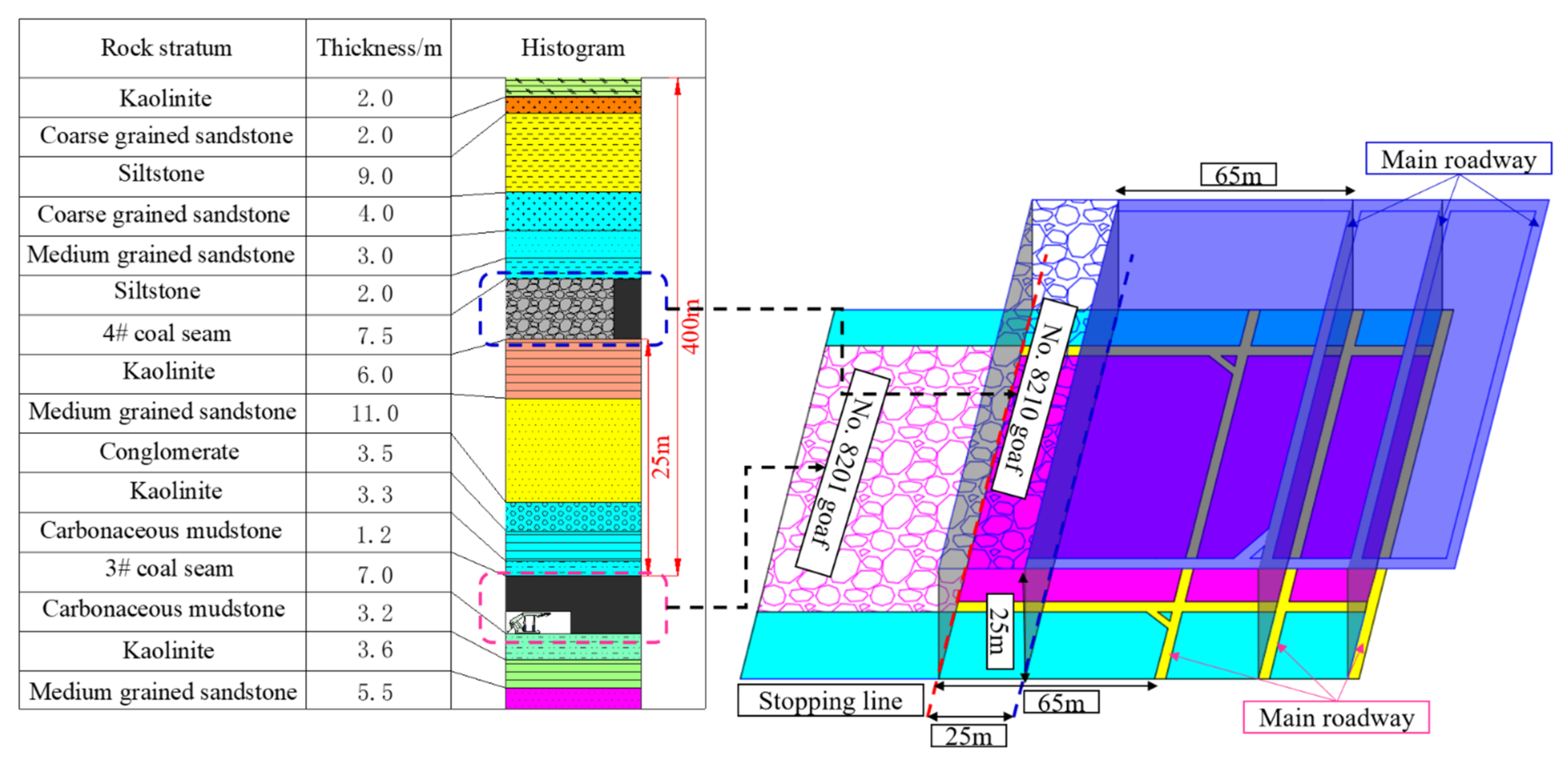
2. Engineering Geological Conditions

A mine is currently mining the overlying No. 4 coal seam and the underlying No. 3 coal seam, both of which are flat seams. The mining method is fully mechanized top coal caving mining. The average thickness of No. 4 coal seams and No. 3 coal seams are about 7.5 m and 7 m, respectively. The average distance between the two coal seams is 25 m. The strike length of the No. 8201 working face is 2517 m, the dip length is 180 m, and the average dip angle is 2°, which corresponds to the No. 8210 goaf of the overlying No. 4 coal seam. The coal seam structure of the No. 8201 working face is complex, with gangue distributed. The lithology of the immediate roof of No. 8201 working face is kaolinite, carbonaceous mudstone, fine sandstone, etc., mainly composed of quartz, and joint fissures are not developed. The lithology of the main roof is medium-grained sandstone, consisting mainly of quartz, with low joint fissure rate, dense sand body cementation, and good stability. The geological histogram of the No. 8201 working face and the position relationship diagram of the upper and lower working faces are shown in Figure 3.
According to the field survey, the width of the coal pillar between the stopping line and the main roadway of the No. 8210 working face is 65 m. To avoid the serious deformation and instability of the main roadway caused by the mining disturbance of the working face, the distance between the stopping line and the main roadway in the No. 8201 working face of the underlying No. 3 coal seam should not be less than 65 m. Therefore, the stopping line of the No. 8201 working face can only be located below the goaf of the upper coal seam. The stopping caving coal distance of the No. 8201 working face is 35 m. If the top coal caving is stopped before the stopping of the fully mechanized top coal caving face, the top coal that has not been caving can be used as the bearing body of the roof rock to reduce the amount of roof rotary subsidence, which is conducive to the stability of the large section stopping space, as shown in Figure 4a [26,27]. If the top coal caving is not stopped, the height of the immediate broken roof cannot reach the position of the main roof, and the turning angle of the key blocks of the main roof becomes larger, which very easily loses stability. It is a threat to the safety of the lower support and the stopping space, as shown in Figure 4b. Therefore, in order to ensure the safety of the stopping space, coal caving is generally stopped within a certain length from the stopping line [28,29,30].

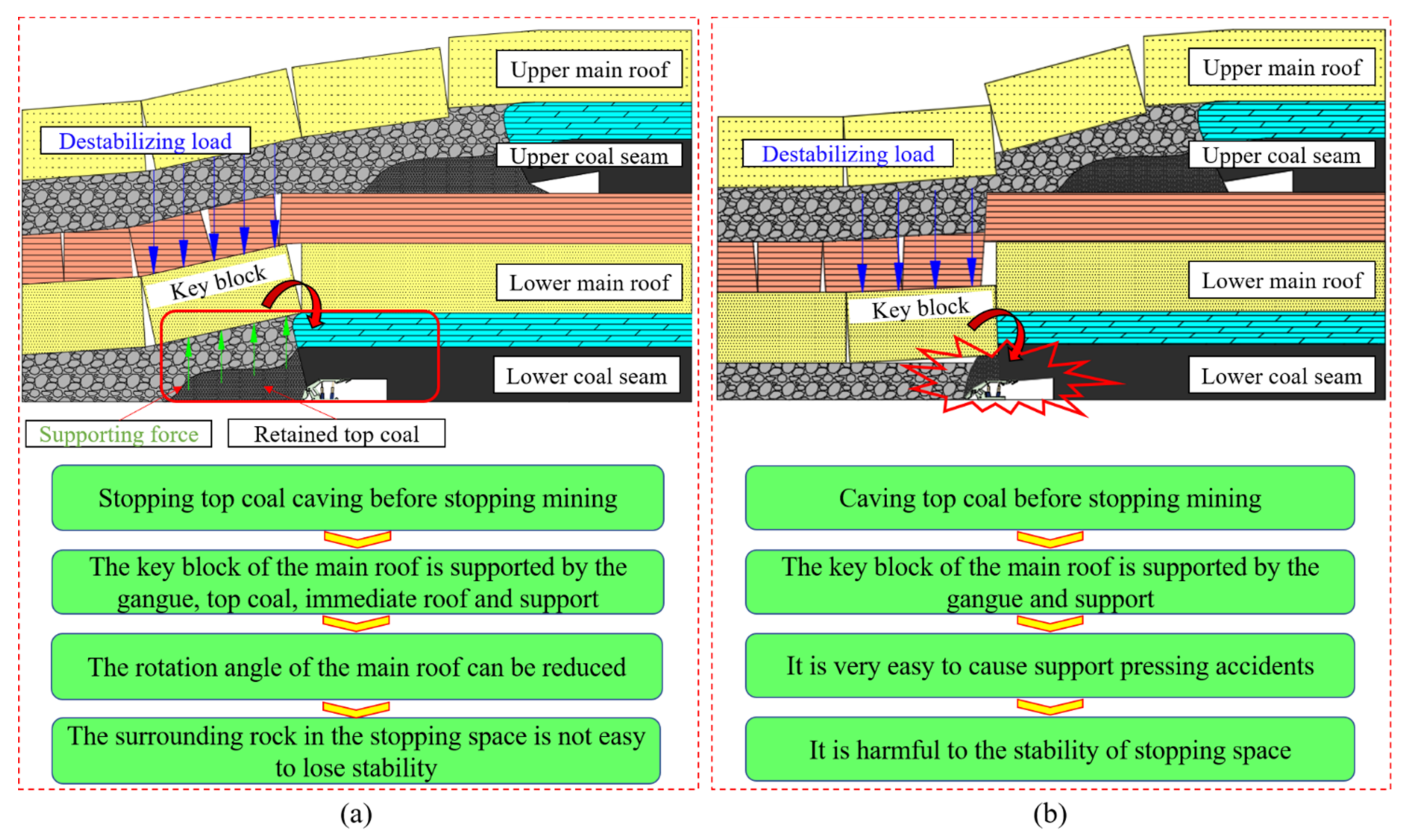
3. Analysis of Stopping Position under Goaf

Different stopping positions under the goaf will also affect the stability of the stop mining space [31]. According to the location relationship between the main roof fracture line and the support, the stopping positions can be divided into three categories. (1) When the main roof fracture line is in front of the support, the key block is supported by the immediate roof, the top coal, and the support. With the withdrawal of the lower support, the support ability of the support to the main roof is weakened, and the key block is prone to instability, which brings great hidden dangers to the safety of the stopping mining space, as shown in Figure 5a. (2) When the main roof fracture line is above the support, the key block is supported by the gangue, the top coal, the immediate roof, and the support. To ensure the stability of the key block, enough top coal should be reserved behind the support. If the parking distance is short, the key block easily loses stability, and the support below the key block is difficult to withdraw, as shown in Figure 5b. (3) When the main roof fracture line is behind the support, the key block is supported by the gangue and the top coal, and its rotary instability has little impact on the stopping mining space. At this time, the stopping mining space is under the protection of the cantilever beam structure of the main roof, which is the best stopping position, as shown in Figure 5c. In comparison, the stopping positions (1) and (2) should be avoided in actual production. The reasonable stopping position under the goaf should ensure that the fracture line of the key block of the main roof is behind the support.

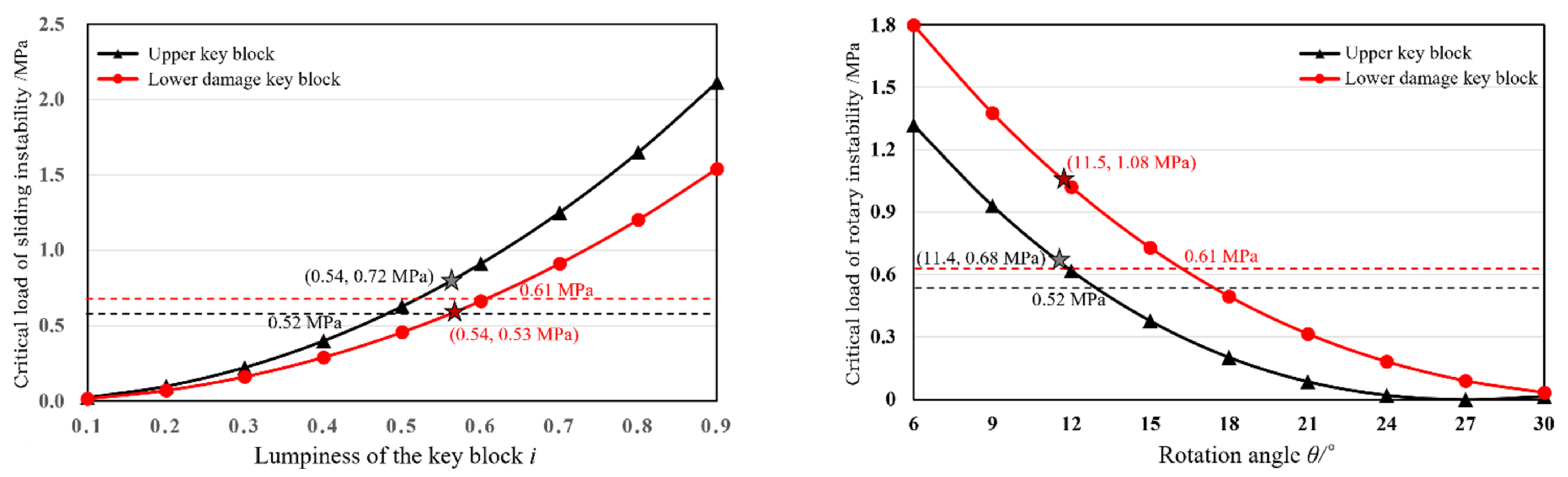
4. Stability Analysis of Key Blocks in Close Distance Coal Seam Mining

The No.4 coal seam was mined first, its main roof collapsed, and the goaf has been compacted. The No.3 coal seam is being mined. The distance between the two coal seams is 25 m, which belongs to a close-distance coal seam. Therefore, it is necessary to consider the damage of the overlying coal seam mining to its floor strata. According to the measured data of the upper coal seam panel mining, the floor damage depth is 8.5 m. When the lower coal seam is mined, its key block is locally damaged and interacts with the key block of the upper coal seam, as shown in Figure 6.
The main roof of the upper coal seam shall bear the rock strata load with a thickness of 20 m, about 0.52 MPa. The stability of the key block in the upper coal seam is analyzed. The average length of the key block is 19.7 m. In the periodic weighting stage, the critical loads for sliding instability and rotary instability are quh and quz, and the expression is as follows [32]:
i u h = cos θ 1 tan φ + sin θ 1 1 + tan θ 1 tan φ 1 tan θ 1 tan φ q u h = 5 i u h 2 [ σ t ] 15 i u h 2
q u z = η σ c i u sin θ 1 2 2 cos θ 2 + i u + sin θ 1 tan θ 1
In the formula:
  • iu is the lumpiness of the key block in the upper coal seam;
  • iuh is the critical lumpiness for sliding instability of the key block;
  • θ1 is the rotating angle of the key block, °;
  • [σc] is the ultimate compressive of rock mass, MPa;
  • [σt] is the ultimate tensile strength of rock mass, MPa;
  • tanφ and η are the friction coefficient between rock blocks, taken as 0.3.
Now, carry out a mechanical analysis on the damaged main roof of the lower coal seam. The top 2.5 m of the main roof rock is damaged by the mining of the upper coal seam, and the sequence degree is 0.77. Meanwhile, when the working face is mining, the average length of its key block is 19.1 m. In the periodic pressure stage, the key block’s critical loads qlh and qlz for sliding instability and slewing instability are as follows: (3), (4) [33,34]:
i l h = cos θ 2 tan φ + sin θ 2 1 + tan θ 2 tan φ 1 tan θ 2 tan φ q l h = 5 i l h 2 [ σ t ] ψ 15 i l h 2
q l z = η σ c ψ i l sin θ 2 2 2 cos θ 2 + i l + sin θ 2 tan θ 2
In the formula:
  • il is the lumpiness of the key block in the lower coal seam;
  • ilh is the critical lumpiness of the key block for sliding instability;
  • θ2 is the rotation angle of the key block, °;
  • ψ is sequence degree, and its value is 0.77.
From this, we can obtain the curves of critical load, lumpiness, and rotation angle of the damaged key block in the lower coal seam, as shown in Figure 7.
Obtained by calculation: the critical loads of the key block in the upper coal seam are 0.72 MPa and 0.68 MPa, which are both greater than the load value of the overlying load layer of 0.52 MPa. Therefore, when mining the lower coal seam, it is only necessary to consider the stability of the damaged main roof key blocks and its load layer. The load of the damaged key block in the lower coal seam is 0.53 MPa. The balance force of the damaged key block cannot bear the load of 0.61 MPa. However, because the hydraulic support provides a bearing capacity close to 1 MPa, the key block of the damaged basic roof will not slide and lose stability when mining in the lower coal seam. At the same time, the load of the damaged key block in the lower coal seam is 1.08 MPa, which can balance itself. Therefore, in view of the damage to the main roof strata of the lower coal seam caused by the mining of the upper coal seam, when mining in the lower coal seam working face, the key blocks will not slide and rotate instability, which can ensure safe mining.

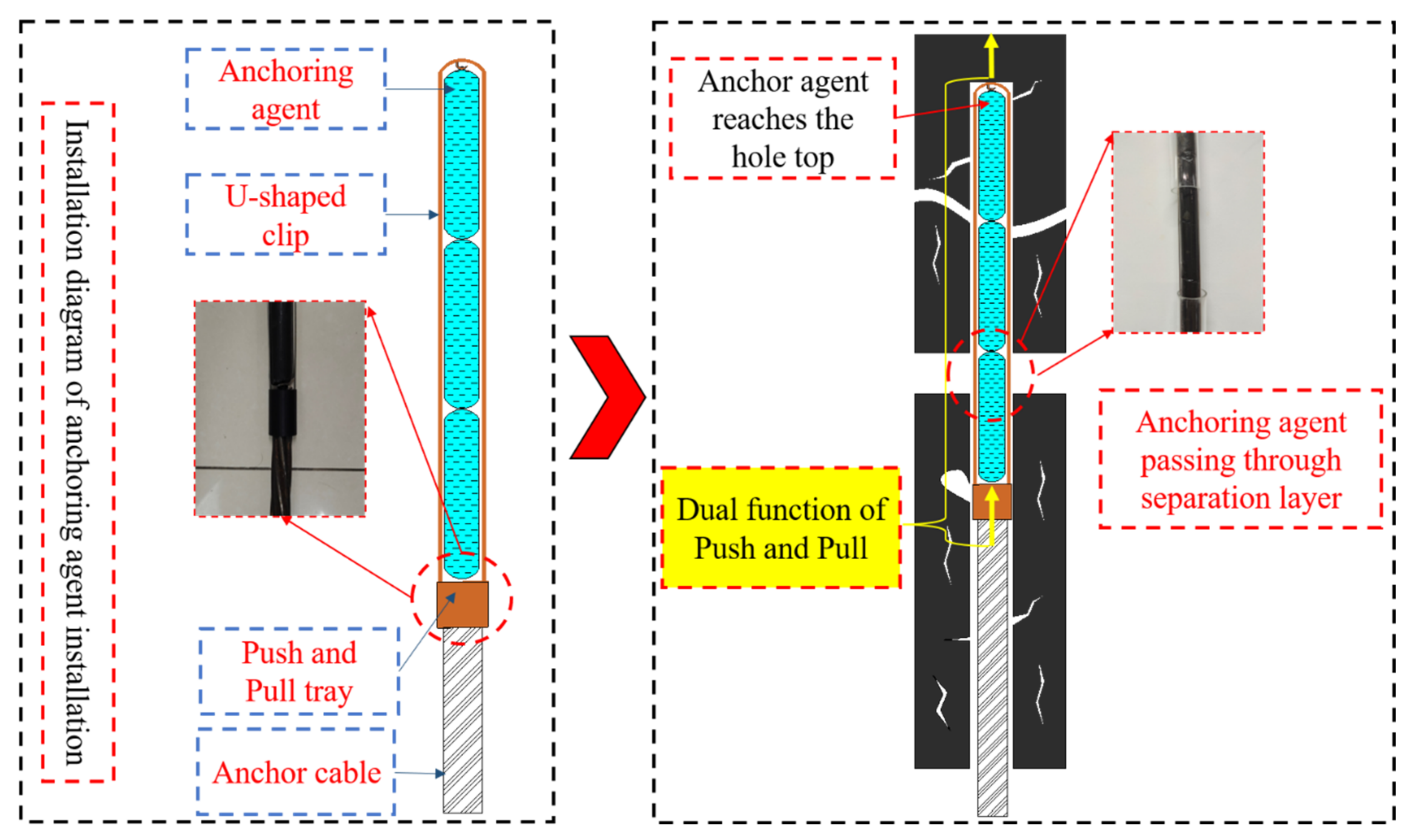
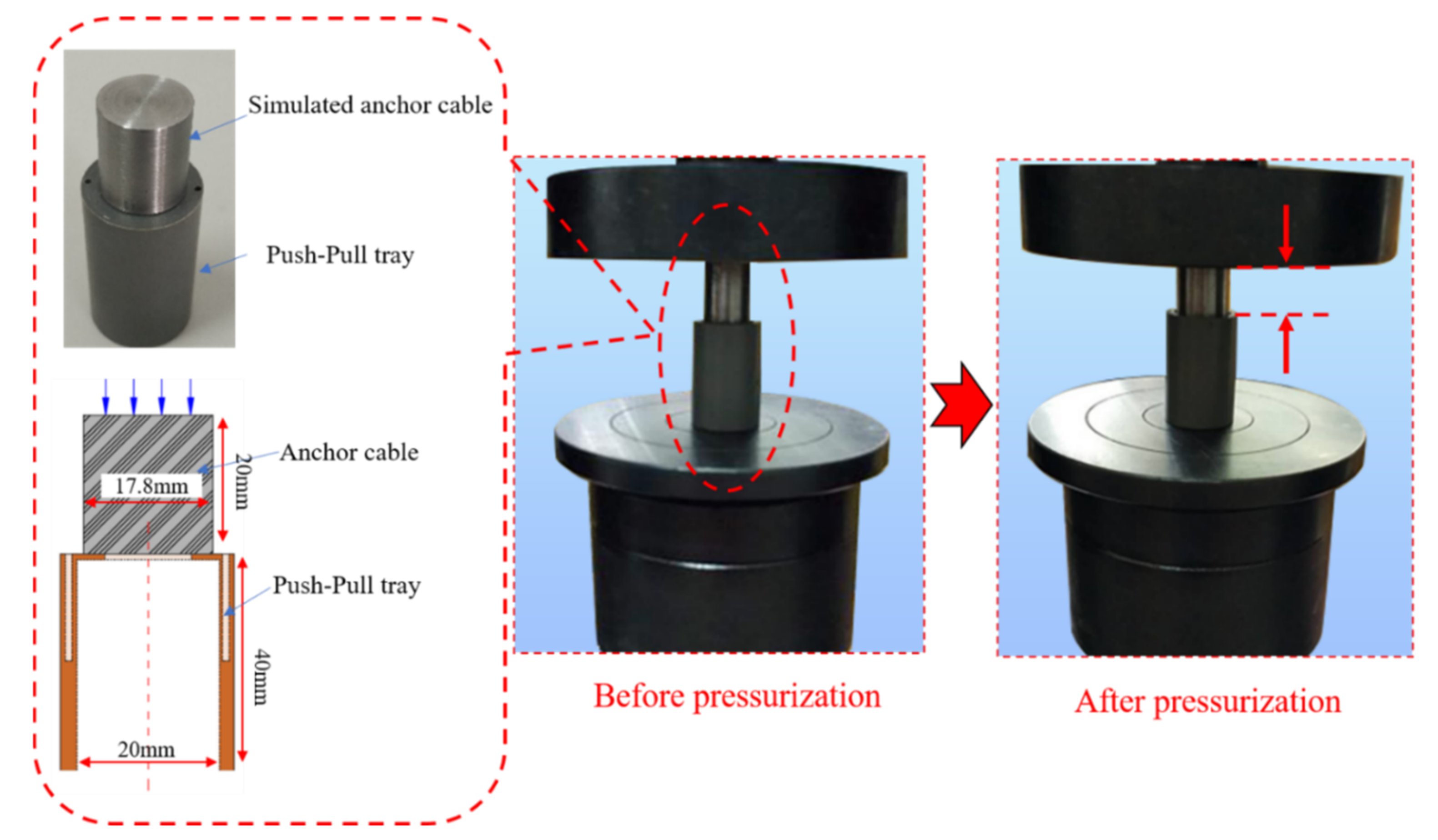
5. “Anchorage with Push and Pull Equipment-Embedded Anchorages and Trays” Integral Anchoring Technology

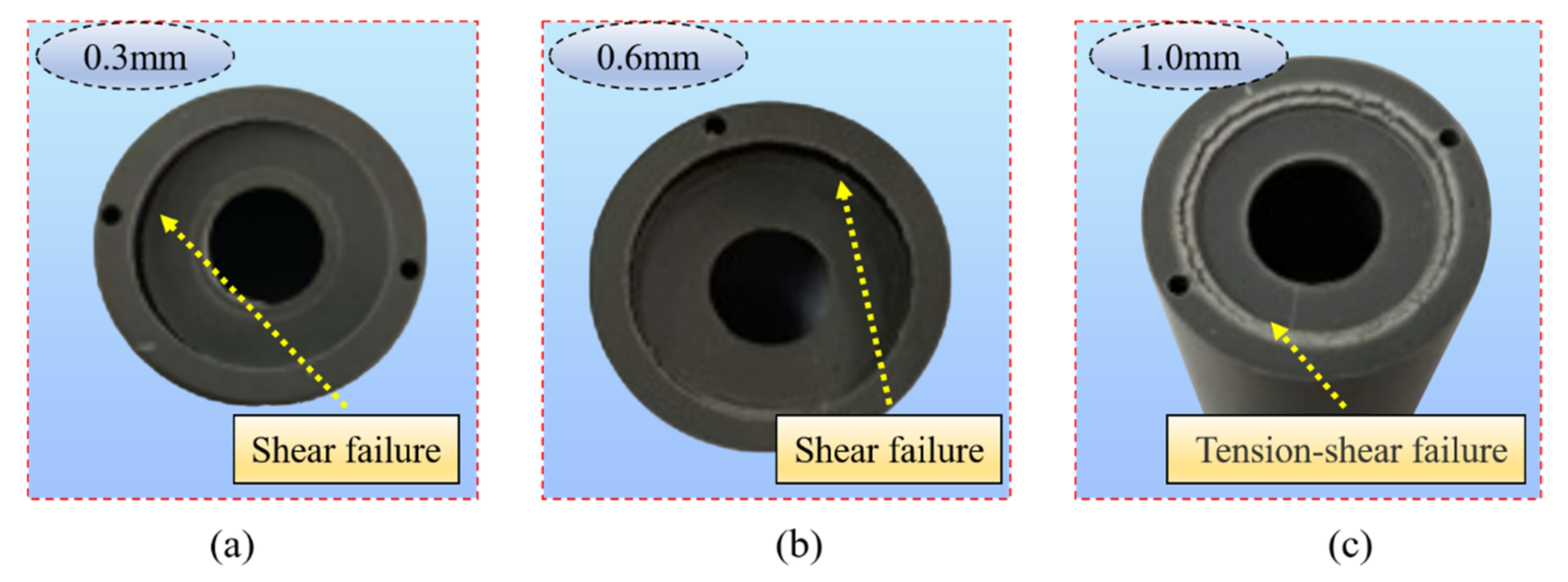
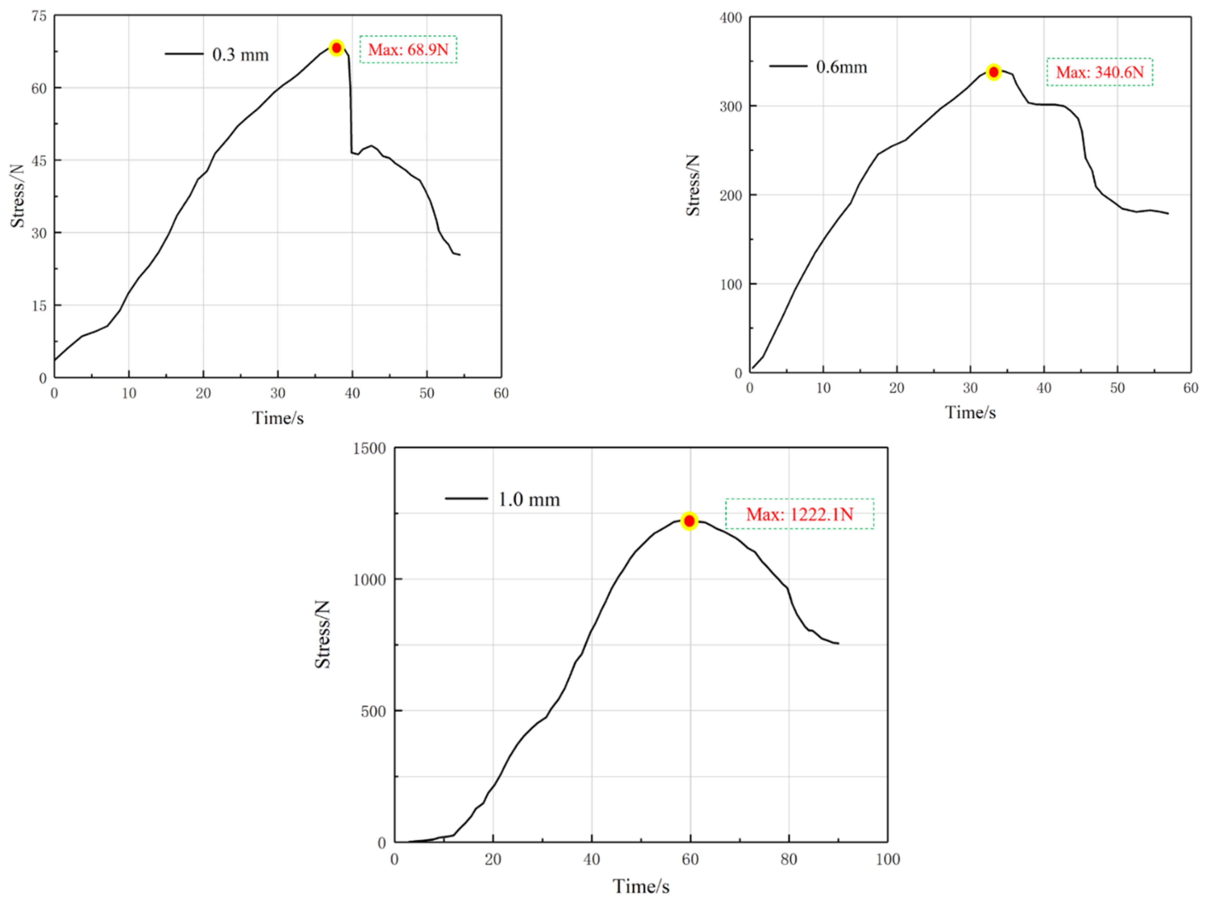
5.1. Development of Anchorage with Push and Pull Equipment

The stopping space of a fully mechanized top coal caving working face is characterized by a large section span, large top coal thickness, and unsynchronized deformation of roof coal and rock strata, which easily causes layer separation and dislocation. Moreover, the strength of the top coal is low, and cracks are easily produced under the influence of mining pressure. Especially, the top coal above the hydraulic support is seriously crushed by the extrusion of the upper roof and support. To accurately understand the broken situation of the top coal in the stopping mining space, the top coal above the stopping mining space in the final mining stage is peeked by the borehole peep method, as shown in Figure 8. The coal body in the borehole is severely broken, the hole-forming effect is poor, the cracks are seriously developed, and there are obvious phenomena of delamination dislocation and hole collapse. The broken top coal has severely challenged the control of surrounding rock in the stopping mining space.
Bolts-anchor cable support is a common means to realize effective control of surrounding rock, and the installation of an anchoring agent is an important link in the supporting operation. At present, the anchoring agent pushing generally adopts the method of unconstrained whole pushing, which can improve the installation efficiency of the anchoring agent compared with staged pushing. However, when there is delamination or hole collapse in the roof drilling hole, the front-end anchoring agent can easily get stuck in the delamination or hole collapse. If it continues to push in, the anchoring agent will bend and then be cut and leaked by sharp coal rock. Because the anchoring agent leaked in advance and failed to reach the anchoring point at the bottom of the hole, the anchoring effect could not be achieved. The unconstrained pushing experiment of the anchoring agent was carried out using a transparent acrylic pipe to simulate the drilling hole, as shown in Figure 9.
If push and pull technology is adopted, the problem of anchoring agent pushing can be effectively solved. The push and pull anchoring equipment is shown in Figure 10. The anchorage with push and pull equipment comprises a push–pull tray and a U-shaped clip. The pushing force of the anchor cable acts on the bottom tray and is transmitted upwards through the U-shaped clip, thus forming a double force of pushing and guiding the middle anchoring agent in the same direction. The U-shaped clip has a certain rigidity, which can dredge the drilling hole and guide the anchoring agent to reach the top of the drilling hole smoothly through the delamination or hole collapse area. Then, the anchor machine is used to push the anchor cable. When the anchor cable pierces the tray, stir the anchoring agent. The effect of anchoring with push and pull is shown in Figure 11. The equipment has a simple structure and good stability and fundamentally solves the problems of easy hole plugging, difficult pushing, and poor anchoring effect of the anchoring agent.
The push–pull tray is the key equipment to bear the push force of the anchor cable, fix the U-shaped clip, and realize the double force of “push” and “pull”. The push–pull tray in kind is shown in the figure. The push–pull tray should not be damaged during normal pushing to ensure that the anchoring agent can reach the hole top smoothly. After that, the top of the tray is damaged by a manual pushing force, and the anchor cable passes through the tray to stir the anchoring agent. To meet the above requirements, it is necessary to test the mechanical properties of the top plate of the push–pull tray. The push–pull tray is made of brittle and easily cracked plastic. To ensure that it is pierced by the anchor cable after lifting the anchoring agent, the top plate of the pushing tray needs a reasonable thickness. Therefore, the thickness of the top plate is 0.3 mm, 0.6 mm, and 1 mm, respectively, for the mechanical loading test, and the test process is shown in Figure 12.
The failure pattern of the top plate after the loading test is shown in Figure 13. the top plate of 0.3 mm and 0.6 mm suffered shear failure, whereas that of 1 mm suffered tensile shear failure. The time–load curves for different top plate thicknesses are shown in Figure 14. The maximum load that the 0.3 mm thick top plate can carry is 68.9 N; for the 0.6 mm thick top plate, the maximum load is 340.6 N; the 1.0 mm thick top plate is loaded with a maximum load of 1222.1 N.
The measured mass of the push–pull tray and U-shaped clip M1 = 70 g, the mass of the anchor agent M2 = 1500 g, taking the acceleration of gravity g = 10 N/kg, resulting in the total gravity of the push–pull device and anchor agent G = 15.7 N. Considering the resistance during the pushing process and the unevenness of the anchor cable end, the bearing capacity of the top plate should not be less than 150 N. To ensure that the final tray can be pierced by the anchor cable, the load-bearing capacity of the top plate should not be too large. Combining the peak pressure and the fitting curve of the top plate thickness, as shown in Figure 15, the reasonable thickness of the top plate was finally determined to be 0.5 mm, and the whole size of the push–pull anchorage device is shown in Figure 16.
In order to test the effect of anchorage with push and pull equipment, pull-out experiments were carried out on the anchor cable in the field. The anchor cable can be divided into a free section and an anchorage section in the borehole, as shown in Figure 17. According to the theory of elasticity, the total elongation of the anchor cable should be the elongation of the free section under the pull-out force. If the total elongation of the anchor cable is greater than the theoretical elongation of the free section of the anchor cable, it proves that the stress in the anchorage section is shifted to the deeper part, and the anchorage section is partially failed.
The field test data are shown in Figure 18. The anchor cable anchorage reliability is higher with the use of the integral push–pull anchorage installation process. No. 1 and No. 2 anchor ropes of unconstrained anchorage showed a significant increase in expansion when the pull-out force was greater than 160 kN, and the total elongation of the anchor cable was significantly greater than the theoretical elongation of the anchor cable. There are two reasons for this phenomenon. On the one hand, it is due to the partial failure of the anchor section, resulting in the growth of the free section length of the anchor cable; on the other hand, it is caused by the relative sliding of the anchor cable under the pulling load due to the reduced frictional resistance between the grouted body (bonded body) of the anchor section and the borehole wall. No. 3 and No. 4 anchor cables were installed with a pull-out force of 200 kN, and the elongation of the anchor cable was approximately equal to the theoretical elongation of the free end of the anchor cable, which indicates that no partial anchor failure or relative slippage occurred in the anchor cable anchorage section.

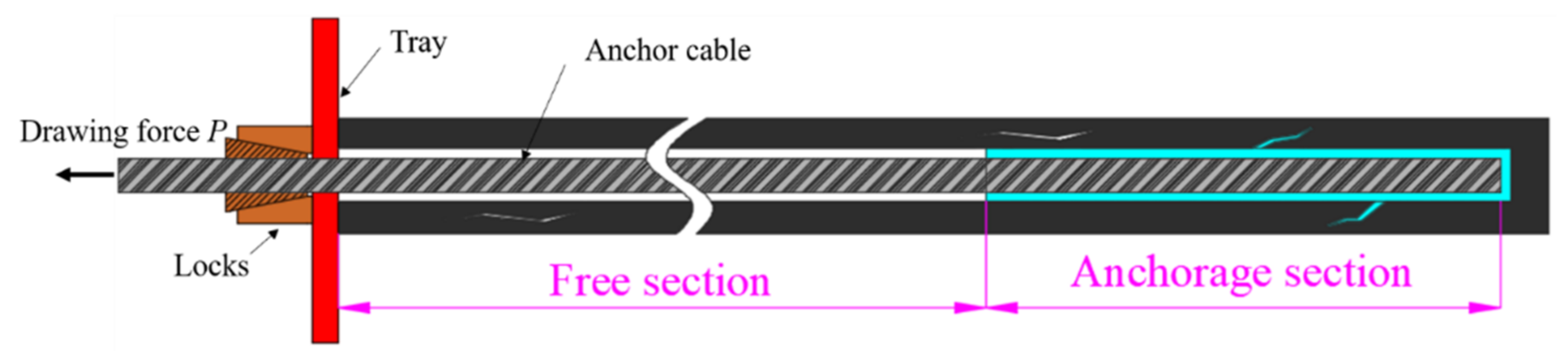
5.2. Anchoring Technology with Embedded Anchorages and Trays

The anchorages of the anchor cables in the stopping space are generally exposed. When the anchor cables exist in the top coal in front of the support during the terminal mining hanging net shifting, the exposed anchorages will prevent the support from shifting the frame with stress, and if the frame continues to be shifted, the anchorages will be damaged, causing the anchor cables to separate from the tray and the support force of the anchor cables to be sharply reduced, resulting in the failure of the support function of the anchor cables, as shown in Figure 19.
In order to overcome the disadvantages of exposed anchorages, a new anchoring method with embedded anchorages and trays has been developed, as shown in Figure 20. The top coal is drilled with a reaming bit to form an embedded slot, the depth of which is such that the anchorages and trays are fully embedded and do not interfere with the support movement. Compared with the exposed anchorages, the technology with embedded anchorages and trays can effectively solve the problems of support movement with pressure, damage to the anchorages, and weakening or invalidating the support system. The effect of embedded anchorages and tray support is shown in Figure 21.
“Anchorage with push and pull equipment-Embedded anchorages and trays” integral anchoring technology in the stopping space can improve the efficiency of anchor cable installation, enhance the effect of anchor cable, strengthen the support capacity of anchor cable, and realize the effect of anchor cable on the surrounding rock.

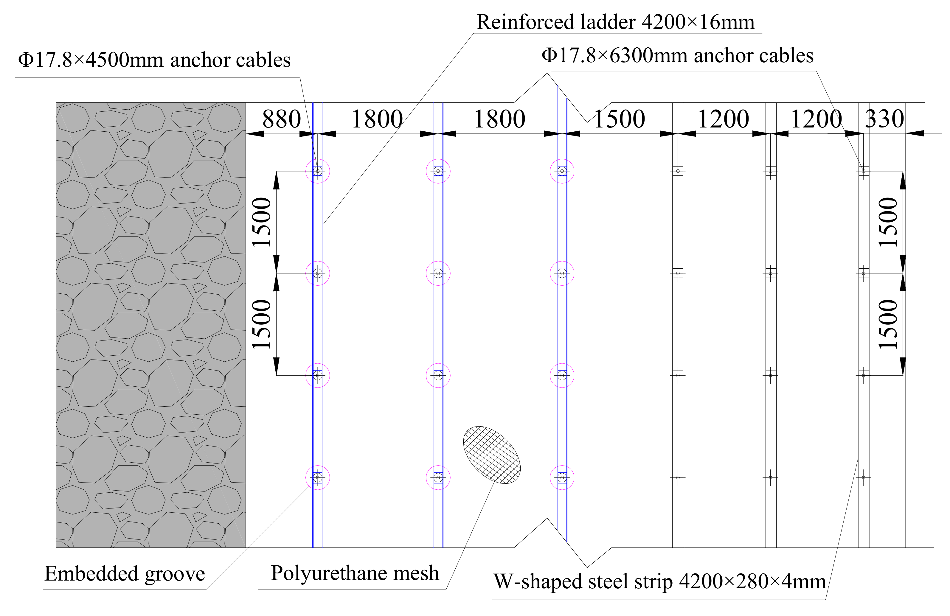
6. Support Schemes for Stopping Space
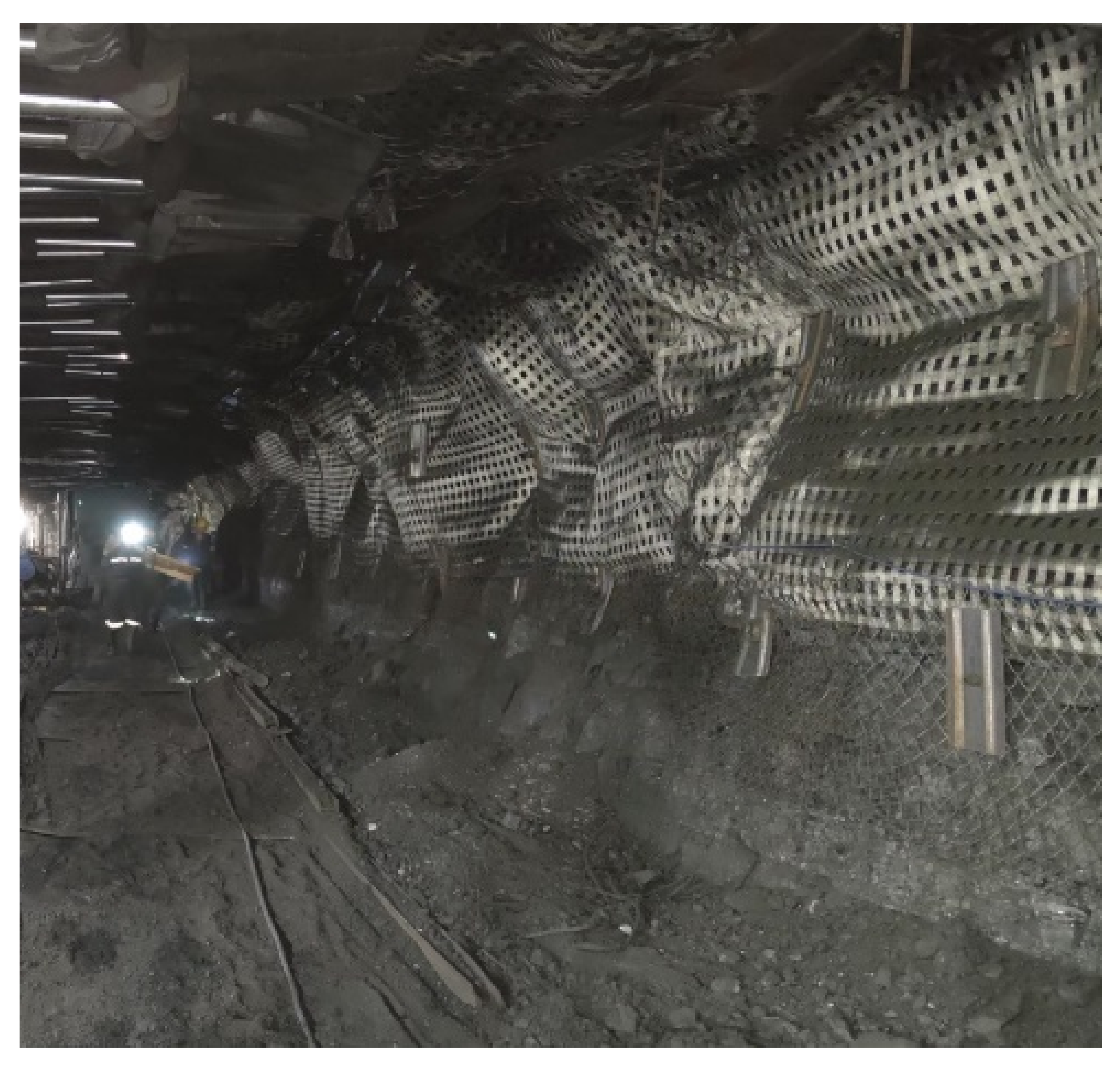
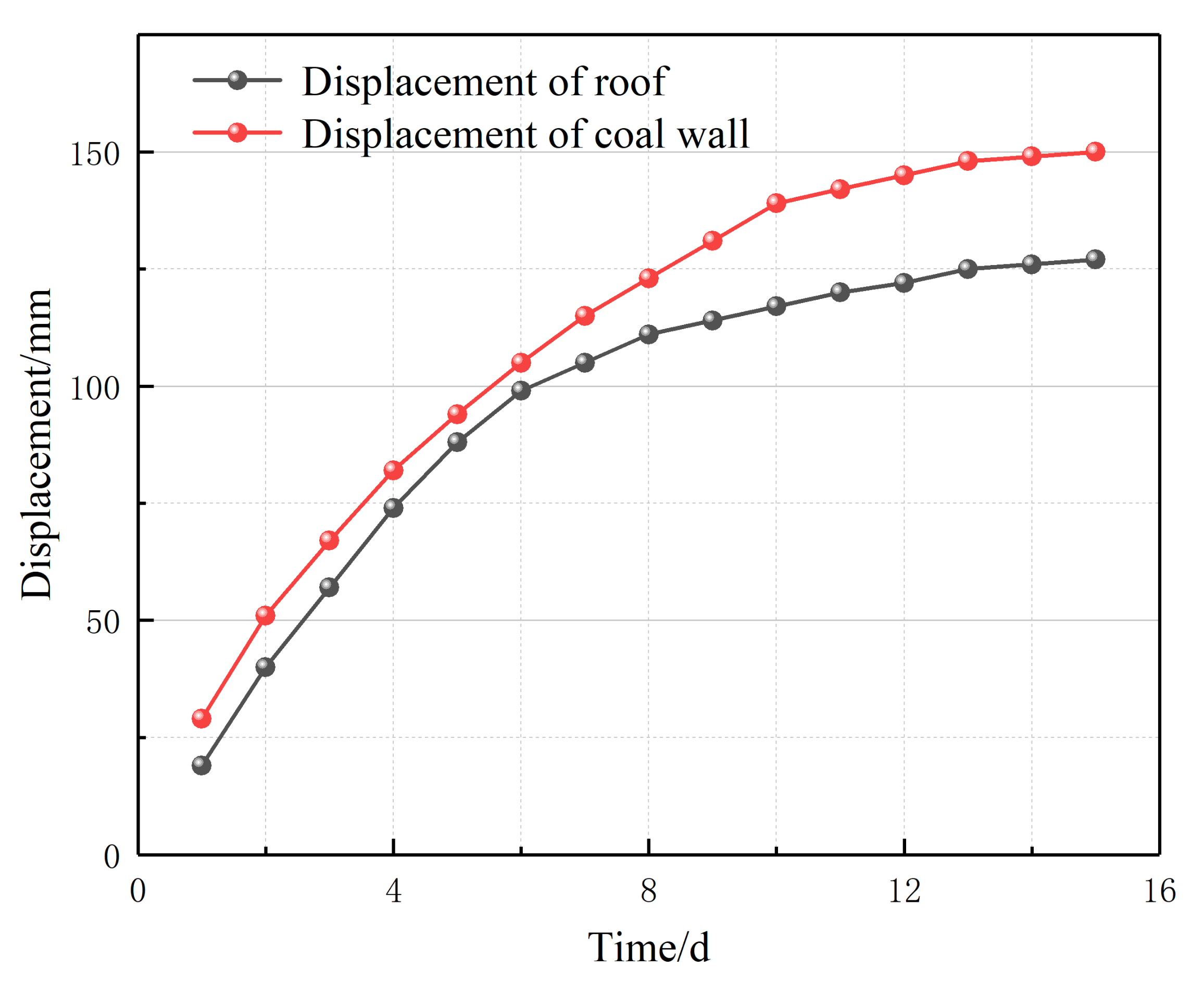
Unlike a traditional roadway, the large section stopping space has a special rock structure, so it is necessary to analyze the structural characteristics of the stopping space when designing the support scheme. As shown in Figure 22, the stopping space consists of the retracement channel, the support bearing area, and the front coal wall area. In terms of the overburden structure, it is safest for the stopping space to be under the protection of the main roof cantilever beam structure. Namely, the main roof fracture line is located behind the support. To satisfy this condition, the working face needs to be stopped just after passing the fracture line (in effect, the stopping point is the end of the working face pressure cycle), followed by the construction of the retracement channel.
According to the characteristics of the surrounding rock structure of the stopping space and the on-site support withdrawal process, different zones of the stopping space have the following different requirements for the support effect. (1) The roof of the retracement channel needs strong support because this area is the key passage area for support withdrawal, so it is necessary to ensure that it is stable before and during support withdrawal. (2) The roof of the support area needs relatively weak support because after the support is withdrawn, the roof of the support area cannot be suspended in a large area and needs to be withdrawn and collapsed at the same time, but it still needs a certain bearing capacity; otherwise, the collapsed roof is close to the support, which easily causes the support to be difficult to pull out. (3) The front coal mass needs surface protection and support to avoid a large area of wall spalling during withdrawal.
Four support schemes are designed according to the actual situation on the site. In order to evaluate the support effects of different support designs, the distribution of the pre-stress field of large-section spatial support for stopping mining is simulated by FLAC3D numerical simulation software. The model is 100 m long, 50 m wide, and 100 m high. The displacement condition is used around the model to fix the boundary. Mohr-Coulomb criterion is selected as the constitutive relation of the model. The anchor cable shall be applied with a pre-tightening force of 120 kN, and the anchor bolt shall be applied with a pre-tightening force of 80 kN. The distribution of the pre-stress field is shown in Figure 23. From the pre-stress field, it can be seen that the bolt (cable) support has changed the stress distribution of the surrounding coal body. The boundary stress of the pre-stress field is 0.02 MPa. The high-stress area is mainly concentrated in the tray and anchorage section. Scheme (a) is that the support area and the retracement channel are supported by anchor cables, and the front coal wall area is supported by bolts. The length of anchor cables is 4500 mm, the spacing is 2500 mm, and the length of bolts is 1700 mm, the spacing is 1600 mm. From the distribution of pre-stress, it can be seen that the high pre-stress is concentrated at the end of the anchor cable and distributed sporadically. The upper roof and the front coal wall do not realize the connection of the pre-stress field. In scheme (b), the spacing of roof anchor cables above the support area is 1800 mm, the spacing of roof anchor cables above the retracement channel is 1200 mm, the length of front coal wall bolts is 1700 mm, and the spacing is 1000 mm. It can be seen from the distribution of pre-stress that the high pre-stress is connected between the upper roof anchor cables, and the low pre-stress field of the upper roof and the front coal wall is connected. In scheme (c), the length of the roof anchor cable above the support area is 4500 mm, and the spacing is 1800 mm. The length of the roof anchor cable above the retracement channel is 6300 mm, and the spacing is 1200 mm. The length of the front coal wall bolt is 1700 mm, and the spacing is 1000 mm. From the distribution of the pre-stress field, it can be seen that the range of the pre-stress field of the roof anchor cable above the retracement channel is larger than that above the support area, and the lower pre-stress field of the upper roof and the front coal wall are interconnected. In scheme (d), the included angle between the right anchor cable of the roof above the retracement channel and the vertical direction is 15 °, and the included angle between the uppermost bolt of the front coal wall and the horizontal direction is 15 °. The other parameters are the same as scheme (c).
From the distribution of the pre-stress field, it can be seen that the control range of the pre-stress field of the roof anchor cable of the retracement channel is large, and the support effect is better than that of the roof of the support area, which reflects the asymmetric support characteristics of relatively strong support in the retracement channel and relatively weak support in the roof above the support area. In addition, the high pre-stress field of the upper roof and the front coal wall are interconnected, which realizes the effective control of the anchor (cable) support over the entire space for mining suspension.
Combined with the distribution of the support pre-stress field and the actual situation on site, and referring to the support design of the stopping space in other working faces of this mine, the asymmetric support scheme of “Partition long and short anchor cables + Integral polyurethane mesh + Embedded anchorages and trays for roof protection” was finally determined, as shown in Figure 24 and Figure 25.

7. Industrial Test

When the 8201 working face enters the final mining stage, the above support scheme will be applied to the field practice. Stop top coal caving before stopping mining of the working face. After stopping top coal caving for 5 m, start to lay the overall polyurethane mesh of the full section, and then the working face will continue to advance without caving until the polyurethane mesh is inserted into the broken top coal that is not placed behind the support for about 1 m, and then drive the retracement channel to form a large section space of about 9 m for stopping mining. “Anchorage with push and pull equipment-Embedded anchorages and trays” integral anchoring technology is used to install the anchor (cable), forming an efficient asymmetric support system. After field comparison, the new anchoring agent installation method can save half the time compared with the traditional installation method. The installation efficiency of the anchoring agent is doubled. The on-site support effect is shown in Figure 26.
In order to evaluate the surrounding rock control effect of the stopping space, measuring points are set to monitor the displacement of the roof and coal wall in the retracement channel. The layout plan of measuring points is shown in Figure 27. The monitoring data are shown in Figure 28. Within 10 days of the arrangement of the measuring points, the displacement of the coal wall in front of the retracement channel maintained a growth trend, but the growth rate gradually slowed down. After 10 days, the growth rate gradually stabilized, and the maximum displacement of the coal wall was 150 mm. At the initial monitoring stage, the roof displacement increased significantly. Due to the support of the hydraulic support, the roof displacement tends to be stable quickly. After 8 days of monitoring, the roof displacement increases and tends to be flat. The maximum roof displacement is 127 mm.

8. Conclusions

(1) It is determined that the stopping line of the lower coal seam can only be located below the goaf of the upper coal seam, and the reasonable stopping position is that the fracture line of the main roof key block is located behind the support.
(2) It is concluded that the key block of the upper coal seam main roof will not lose stability during the mining of the lower coal seam, and the damaged key block of the lower coal seam cannot bear the load of overlying rocks, but it will not lose stability under the supporting action of the support.
(3) Anchorage with push and pull equipment is developed. It is determined that the height of the push and pull tray is 45 mm, the thickness of the top plate is 0.5 mm, and the length of the U-shaped clip is 1575 mm. A new anchoring method of embedded anchorages and trays is proposed to realize the synergetic control of the surrounding rock.
(4) The asymmetric control scheme of “Partition long and short anchor cables + Integral polyurethane mesh + Embedded anchorages and trays for roof protection” is determined. The rock pressure observation shows that it realizes the safe withdrawal of the working face equipment.

Author Contributions

Conceptualization, F.H. and D.C.; Data curation, B.L., Y.W. (Yanhao Wu), and L.S.; Formal analysis, D.W., Z.J., F.G., W.W. and Y.W. (Yiyi Wu); Funding acquisition, F.H. and D.C.; Methodology, Y.W. (Yanhao Wu) and L.S.; Project administration, D.C.; Software, X.M., B.L. and Q.Y.; Supervision, F.H.; Writing—original draft, D.C. and D.W.; Writing—review and editing, D.C., B.L., D.W. and X.M. All authors have read and agreed to the published version of the manuscript.

Funding

This work was supported by the National Natural Science Foundation of China (Grant No.52004286), the National Natural Science Foundation of China (Grant No.51974317), the Fundamental Research Funds for the Central Universities (2021YJSNY01, 2022YJSNY09).

Conflicts of Interest

The authors declare no conflict of interest.

References

  1. Shang, Y.Q.; Kong, D.Z.; Pu, S.J.; Xiong, Y.; Li, Q.; Cheng, Z.B. Study on Failure Characteristics and Control Technology of Roadway Surrounding Rock under Repeated Mining in Close-Distance Coal Seam. Mathematics 2022, 10, 2166. [Google Scholar] [CrossRef]
  2. Chen, D.; Guo, F.; Li, Z.; Ma, X.; Xie, S.; Wu, Y.; Wang, Z. Study on the Influence and Control of Stress Direction Deflection and Partial-Stress Boosting of Main Roadways Surrounding Rock and under the Influence of Multi-Seam Mining. Energies 2022, 15, 8257. [Google Scholar] [CrossRef]
  3. Bhattacharya, M.; Rafiq, S.; Bhattacharya, S. The role of technology on the dynamics of coal consumption–economic growth: New evidence from China. Appl. Energy 2015, 154, 686–695. [Google Scholar] [CrossRef]
  4. Xie, S.; Wang, E.; Chen, D.; Jiang, Z.; Li, H.; Liu, R. Collaborative Control Technology of External Anchor-Internal Unloading of Surrounding Rock in Deep Large-Section Coal Roadway under Strong Mining Influence. J. China Coal Soc. 2022, 47, 1946–1957. [Google Scholar]
  5. Zhang, B.S.; Yang, Z.P.; Ji, C.X.; Guo, Z.F.; Li, H.Y. Research on the Influence of the Key Stratum Position on the Support Working Resistance during Large Mining Height Top-Coal Caving Mining. Adv. Civ. Eng. 2021, 2021, 6690280. [Google Scholar] [CrossRef]
  6. Wang, B.N.; Mu, L.; He, M.M.; Gu, S.C. Mechanism Analysis of Roof Deformation in Pre-Driven Longwall Recovery Rooms Considering Main Roof Failure Form. Sustainability 2022, 14, 9093. [Google Scholar] [CrossRef]
  7. Zhu, C.; Yuan, Y.; Chen, Z.S.; Liu, Z.H.; Yuan, C.F. Study of the Stability Control of the Rock Surrounding Double-Key Strata Recovery Roadways in Shallow Seams. Adv. Civ. Eng. 2019, 2019, 9801637. [Google Scholar] [CrossRef]
  8. Wang, B.N.; Dang, F.N.; Gu, S.C.; Huang, R.B.; Miao, Y.P.; Chao, W. Method for determining the width of protective coal pillar in the pre-driven longwall recovery room considering main roof failure form. Int. J. Rock. Mech. Min. 2020, 130, 104340. [Google Scholar] [CrossRef]
  9. Kang, H.P.; Lv, H.W.; Zhang, X.; Gao, F.Q.; Wu, Z.G.; Wang, Z.C. Evaluation of the Ground Response of a Pre-driven Longwall Recovery Room Supported by Concrete Cribs. Rock. Mech. Rock. Eng. 2016, 49, 1025–1040. [Google Scholar] [CrossRef]
  10. Fei, L.; Jiang, Z.X. Research on Deformation Mechanism of Retracement Channel during Fully Mechanized Caving Mining in Superhigh Seam. Adv. Civ. Eng. 2018, 2018, 1368965. [Google Scholar] [CrossRef]
  11. Xu, J.H.; Miao, X.X.; Pu, H.; Cao, S.G. Determination of reasonable position and stability analysis of finishing cut in fully-mechanized coal face with topped caving. Chin. J. Rock Mech. Eng. 2004, 23, 1981–1985. [Google Scholar]
  12. Yang, R.S.; Li, Y.L.; Zhu, Y.; Xiao, C.L.; Zhao, Y.; Shi, G.L. Study on stability control of equipment removal channel for high cutting mining face under special condition. Coal Sci. Technol. 2017, 45, 10–15. [Google Scholar]
  13. Song, B. Instant Removal Gateway for Large Height Working Face in Soft Coal Seam. Saf. Coal Mines 2014, 45, 136–139. [Google Scholar]
  14. Chen, Z.S.; Yuan, Y.; Zhu, C.; Wang, W.M. Stability Mechanism and Control Factors on Equipment Removal Area under “Goaf-Roof-Coal” Structure. Adv. Civ. Eng. 2021, 2021, 6628272. [Google Scholar] [CrossRef]
  15. Wu, J.N.; Feng, X.W.; Liu, B.K. Rapid removing technology of heavy fully mechanized top coal caving mining face without preset removing gateway. Coal Sci. Technol. 2008, 36, 14–17. [Google Scholar]
  16. Liu, Y.M.; Liu, Y.H.; Gao, M.S. Roof Fracture Characteristics of Deep Mining-pause Space Without Pre-excavation Roadway. Saf. Coal Mines 2016, 47, 197–199. [Google Scholar]
  17. Wang, X.; Ji, W.P.; Li, X.M.; Liu, F.; Zhang, N.B. Study on Position of Withdrawal Entry in Fully Mechanized Caving Face of Extremely Thick Coal Seam. Coal Technol. 2010, 29, 63–65. [Google Scholar]
  18. Ning, J.G.; Wang, J.; Tan, Y.L.; Xu, Q. Mechanical mechanism of overlying strata breaking and development of fractured zone during close-distance coal seam group mining. Int. J. Min. Sci. Technol. 2020, 30, 207–215. [Google Scholar] [CrossRef]
  19. Guo, G.C.; Yang, Y.K. The study of key stratum location and characteristics on the mining of extremely thick coal seam under goaf. Adv. Civ. Eng. 2021, 2021, 8833822. [Google Scholar] [CrossRef]
  20. Xie, S.; Wu, Y.; Guo, F.; Zou, H.; Chen, D.; Zhang, X.; Ma, X.; Liu, R.; Wu, C. Application of Pre-Splitting and Roof-Cutting Control Technology in Coal Mining: A Review of Technology. Energies 2022, 15, 6489. [Google Scholar] [CrossRef]
  21. Pan, W.D.; Zhang, S.P.; Liu, Y. Safe and efficient coal mining below the goaf: A case study. Energies 2020, 13, 864. [Google Scholar] [CrossRef] [Green Version]
  22. Zhang, W.; Zhang, D.S.; Qi, D.H.; Hu, W.M.; He, Z.M.; Zhang, W.S. Floor failure depth of upper coal seam during close coal seams mining and its novel detection method. Energy Explor. Exploit. 2018, 36, 1265–1278. [Google Scholar] [CrossRef] [Green Version]
  23. Vu, T.T. Solutions to prevent face spall and roof falling in fully mechanized longwall at underground mines, Vietnam. Min. Min. Dep. 2022, 16, 127–134. [Google Scholar] [CrossRef]
  24. Małkowski, P.; Niedbalski, Z.; Majcherczyk, T.; Bednarek, Ł. Underground monitoring as the best way of roadways support design validation in a long time period. Min. Min. Dep. 2020, 14, 1–14. [Google Scholar] [CrossRef]
  25. Zhu, C.; Xu, Y.Z.; Wu, Y.X.; He, M.C.; Zhu, C.Q.; Meng, Q.X.; Lin, Y. A hybrid artifi cial bee colony algorithm and support vector machine for predicting blast-induced ground vibration. Earthq. Eng. Eng. Vib. 2022, 21, 861–876. [Google Scholar]
  26. Xie, S.R.; Wu, Y.Y.; Ma, X.; Chen, D.D.; Guo, F.F.; Jiang, Z.S.; Li, H.; Zou, H.; Liu, R.P.; Zhang, X. Reasonable stopping method and retracement channel support at fully mechanized top coal caving working face of 15 m extra-thick coal seam: A case study. Energy Sci. Eng. 2022. [Google Scholar] [CrossRef]
  27. Chen, D.; Wu, Y.; Xie, S.; Guo, F.; He, F.; Liu, R. Reasonable Location of Stopping Line in Close-Distance Underlying Coal Seam and Partition Support of Large Cross-Section Roadway. Int. J. Coal Sci. Technol. 2022, 9, 55. [Google Scholar] [CrossRef]
  28. Singh, G.S.P.; Singh, U.K. Assessment of goaf characteristics and compaction in longwall caving. Min. Technol. 2011, 120, 222–232. [Google Scholar] [CrossRef]
  29. Alehossein, H.; Poulsen, B.A. Stress analysis of longwall top coal caving. Int. J. Rock Meck. Min. 2010, 47, 30–41. [Google Scholar] [CrossRef]
  30. Klishin, V.I.; Fryanov, V.N.; Pavlova, L.D.; Opruk, G.Y. Modeling top coal disintegration in thick seams in longwall top coal caving. J. Min. Sci. 2019, 55, 247–256. [Google Scholar] [CrossRef]
  31. Wang, X.Z.; Ju, J.F.; Xu, J.L. Theory and applicable of yield mining at ending stage of fully-mechanized face in shallow seam at Shendong mine area. J. Min. Saf. Eng. 2012, 3, 151–156. [Google Scholar]
  32. Qian, M.G.; Miao, X.X.; Xu, J.L. Theoretical Study of Key Sratum in Ground Control. J. China Coal Soc. 1996, 21, 2–7. [Google Scholar]
  33. Xie, S.R.; Wu, Y.Y.; Guo, F.F.; Chen, D.D.; Wang, E.; Zhang, X.; Zou, H.; Liu, R.P.; Ma, X.; Li, S.J. Interaction Mechanism of the Upper and Lower Main Roofs with Different Properties in Close Coal Seams: A Case Study. Energies 2022, 15, 5533. [Google Scholar] [CrossRef]
  34. He, S.S.; Xie, S.R.; Song, B.H.; Zhou, D.Q.; Sun, Y.D.; Han, S. Breaking laws and stability analysis of damage main roof in close distance hypogynous seams. J. China Coal Soc. 2016, 41, 2596–2605. [Google Scholar]
Figure 1. Schematic diagram of stopping mining under solid coal.
Energies 15 08498 g001
Figure 2. Schematic diagram of stopping mining under goaf.
Energies 15 08498 g002
Figure 3. Geological histogram of panel and position relationship diagram of the upper and lower working faces.
Energies 15 08498 g003
Figure 4. Schematic diagram of no top coal caving and top coal caving before stopping mining. (a) No top coal caving before stopping mining. (b) Top coal caving before stopping mining.
Energies 15 08498 g004
Figure 5. Schematic diagram of different stopping positions under the goaf. (a) The main roof fracture line is in front of the support. (b) The main roof fracture line is above the support. (c) The main roof fracture line is behind the support.
Energies 15 08498 g005
Figure 6. Interaction between key blocks of the upper main roof and lower main roof.
Energies 15 08498 g006
Figure 7. Linkage analysis of upper and lower main roof key blocks.
Energies 15 08498 g007
Figure 8. Borehole peep of top coal. (a) Delamination occurred in the borehole. (b) Collapse occurred in the borehole. (c) Cracks occurred in the borehole.
Energies 15 08498 g008
Figure 9. Disadvantages of unrestrained integral pushing anchoring agent.
Energies 15 08498 g009
Figure 10. Schematic diagram of anchorage with push and pull equipment.
Energies 15 08498 g010
Figure 11. Effect diagram of anchorage with push and pull equipment.
Energies 15 08498 g011
Figure 12. Mechanical loading test of push–pull tray.
Energies 15 08498 g012
Figure 13. Failure patterns of top plates of different thicknesses. (a) shear failure; (b) shear failure; (c) tensile shear failure.
Energies 15 08498 g013
Figure 14. Loading curves for different thicknesses of the top plate. (a) Plate thickness 0.3 mm; (b) Plate thickness 0.6 mm; (c) Plate thickness 1.0 mm.
Energies 15 08498 g014
Figure 15. Peak stress with fitting curve for top tray thickness.
Energies 15 08498 g015
Figure 16. Dimensional drawing of the push–pull anchorage device (a) Home view of push–pull tray. (b) Home view of U-shaped clip.
Energies 15 08498 g016
Figure 17. Schematic diagram of the anchor cable in the borehole.
Energies 15 08498 g017
Figure 18. Pull-out test results for anchor cables.
Energies 15 08498 g018
Figure 19. Disadvantages of exposed anchorages of the anchor cable.
Energies 15 08498 g019
Figure 20. Schematic diagram of embedded anchorages and trays.
Energies 15 08498 g020
Figure 21. Comparison of the effect between exposed and embedded anchorages and trays.
Energies 15 08498 g021
Figure 22. Illustration of the stopping space zoning in fully mechanized top coal caving mining method.
Energies 15 08498 g022
Figure 23. Schematic Diagram of Prestressing Field of Different Support Schemes (ad).
Energies 15 08498 g023
Figure 24. Asymmetric support parameters of stopping space.
Energies 15 08498 g024
Figure 25. Top view of stopping space support.
Energies 15 08498 g025
Figure 26. Effect picture of on-site support.
Energies 15 08498 g026
Figure 27. Layout of measuring points.
Energies 15 08498 g027
Figure 28. Deformation of surrounding rock.
Energies 15 08498 g028
Publisher’s Note: MDPI stays neutral with regard to jurisdictional claims in published maps and institutional affiliations.

