Review

Model Predictive Control for Solid State Transformers: Advances and Trends

1
Department of Electrical and Computer Engineering (DEEC), University of Coimbra—Pole 2, P-3030-290 Coimbra, Portugal
2
Instituto de Telecomunicações, University of Coimbra—Pole 2, P-3030-290 Coimbra, Portugal
3
Eneida.io, Rua Alexandre Herculano 21B, P-3000-104 Coimbra, Portugal
*
Author to whom correspondence should be addressed.
Energies 2022, 15(22), 8349; https://doi.org/10.3390/en15228349
Submission received: 2 September 2022 / Revised: 29 September 2022 / Accepted: 11 October 2022 / Published: 8 November 2022

Abstract

:
Due to its high functionality, the solid state transformer (SST) represents an emerging technology with huge potential to replace the conventional low-frequency transformer (LFT) in a wide range of applications, including railway traction, smart grids, and others. On the other hand, model predictive control (MPC) has proven to be a highly promising control approach for several power electronics systems, especially those based on multiple power converters. Considering these facts, over recent years, different MPC techniques have been proposed for different types of SSTs. In addition to that, numerous MPC strategies have also been investigated for various power converters topologies that can be used in SSTs. However, a paper summarizing and discussing MPC strategies in the framework of SSTs has not yet been proposed in the literature, being the main goal of this work. In this paper, all the existing MPC techniques in complete SST topologies will be presented and discussed. In addition, for the sake of the example, an overview of MPC strategies in converter topologies typically used in SSTs will also be presented.

1. Introduction

Over recent decades, the conventional low-frequency transformer (LFT) has been demonstrated as a key element for AC voltage regulation and galvanic isolation in many applications, including AC power distribution and transmission, railway traction systems, industry, and others. However, as a purely passive element, the conventional transformer cannot provide important functionalities, such as power flow and power quality control. To achieve that, beyond the typically heavy and bulky transformer, external power electronics systems are typically required. On the other hand, given the fact that it operates in AC, several AC/DC conversion systems are also typically necessary to integrate different types of DC loads, sources and grids (e.g., energy storage systems, PV generation and HVDC transmission lines). Another limitation of LFTs relies on the fact that they are designed to operate at low frequency (dozens of Hz). As a consequence of this, heavy and bulky solutions are usually unavoidable even in weight- and space-critical applications (e.g., railway traction systems) [1,2,3].
In light of these facts, the solid state transformer (SST) is seen as a highly promising technology to replace the current LFT-based electrical conversion systems [3,4,5,6,7,8]. This might include simple AC/AC conversion systems essentially using an LFT, or more complex systems in which various power electronics converters (PECs) are coupled to an LFT, such as wind energy conversion systems [5], railway traction systems [8], and EV charging stations [7]. In basic terms, an SST corresponds to an integrated system that uses PECs and at least one high-frequency transformer (HFT). Thus, in comparison with conventional conversion systems using LFTs, an SST can bring several advantages. Firstly, as in an SST, the HFTs typically operate at a very high frequency (from a few to dozens of kHz) [9,10], for a given nominal power, SSTs can present significantly lower size and weight [1,11]. Another huge advantage of SSTs is that they can provide DC ports. This eliminates the need of using several individual AC/DC conversion systems for DC equipment integration. Furthermore, by having an integrated system providing AC and DC ports, a harmonized interconnection of AC and DC systems can be easier to achieve, with the SST controlling the power flowing through these ports. For the sake of clarity, and given the fact that SSTs will be used to replace LFT-based electrical conversion systems which always have at least one MVAC (or HVAC) port, in this paper, it will be considered that a complete SST must always have at least one AC port. In addition, galvanic isolation must always be present in an SST. According to these two aspects, stand-alone converters, multi-converter topologies without galvanic isolation and isolated DC/DC converters will not be considered as complete SST topologies, but as part of them.
Over recent years, several control strategies have been investigated for different types of SST. However, a great deal of these control techniques are based on classical linear control methods, such as PI-control with a modulation stage [2,10,12,13]. Due to a typical cascaded control architecture with a control loop being necessary for each control objective, this conventional control approach might present performance limitations. This particularly happens in multi-variable and multi-converter systems, such as complex SST architectures. This issue, coupled with the development and trivialization of digital controllers has motivated the development of more advanced control techniques, such as Model Predictive Control (MPC). MPC uses the system mathematical model to minimize a cost function, considering a limited prediction horizon [14,15,16,17]. By virtue of its control principle, in comparison with more conventional control methods, MPC typically provides a faster dynamic response with no overshoot, as demonstrated in several studies [18,19]. In addition, MPC can also provide an easier inclusion of system constraints and non-linearities, as well as an easier inclusion of multiple control objectives in the control design [15,19,20]. Based on the considered control set, MPC strategies are typically divided into two different sub-types: continuous control set MPC (CCS-MPC) and finite control set MPC (FCS-MPC). In CCS-MPC, the controller considers a continuous control action, thus requiring a modulation stage. On the other hand, FCS-MPC considers the discrete nature of power converters. In this type of control, an optimal switching state is typically selected and applied to the converter during a full sampling period. Alternatively, an optimal switching sequence can also be selected for various sampling periods. In comparison with CCS-MPC, FCS-MPC does not require a modulator and the overall control scheme design is usually simpler. Nevertheless, the absence of a modulation stage has some inherent problems, such as variable switching frequency (typically undesirable). Moreover, since in FCS-MPC the switching states are kept during full sampling periods, larger sampling periods are typically needed to achieve equivalent steady-state performance as in CCS-MPC.
The highly promising features of MPC have led to the proposal of control strategies, not only for different types of SST (complete topologies), but also for promising converter topologies that can be included in an SST. Even though there are some review articles about SST in the literature [2,4,21,22,23], these works mainly focus on generic aspects, such as SST topologies and applications. Thus, a review paper discussing the latest advances and trends of MPC in the framework of SSTs has not yet been proposed in the literature. Considering these facts, this paper assembles and discusses, in a single reference, all the existing MPC strategies in SSTs. Additionally, for the sake of example, an overview of MPC techniques in some of the most commonly investigated and promising converter topologies for SSTs will also be presented.
The remainder of this paper is organized as follows: in Section 2 all the existing works using MPC in complete SST topologies are presented and discussed; Section 3 presents an overview of MPC techniques in promising converter topologies typically used in SSTs; finally, Section 4 presents the main conclusions of this work.

2. MPC Strategies in Complete SST Configurations

In this section, the existing MPC strategies in complete SST structures are presented and discussed. Different MPC techniques have been proposed for different SST topologies, which can be based on non-modular or modular configurations. For the sake of clarity, the existing MPC strategies applied to non-modular SST configurations are presented in Section 2.1, while MPC techniques in modular SST topologies are discussed in Section 2.2.

2.1. MPC in Non-Modular SST Configurations

The existing works using MPC techniques in non-modular SST configurations are summarized in Table 1. This table indicates the work reference, SST application (according to the respective authors), SST conversion stages, used power converters, type of MPC (FCS-MPC, CCS-MPC or both), if MPC is used in all stages, and the used physical controllers. These works will be described next, according to the following order: first, MPC strategies in AC/AC SSTs without [24,25,26,27] and with [28,29,30] internal DC-links are addressed; then, the use of MPC in AC/DC SSTs with internal DC-links [31,32] are described; finally, the existing MPC strategies in a flexible single-stage SST topology [33,34,35] are also discussed.
In [24], an MPC strategy is proposed for a matrix-converter-based SST whose topology is shown in Figure 1. The considered system corresponds to a single-stage AC/AC SST formed by two matrix converters in back-to-back configuration, connected through an HFT. The system provides two AC ports, which can operate at different voltage and frequency. Furthermore, even though in [24] only unidirectional power flow conditions are considered (from the grid to the load-side), this SST enables bidirectional power flow. The proposed control system diagram is demonstrated in Figure 2.
The SST control strategy is fully based on FCS-MPC, which means that the control actions for both converters are directly selected from the possible converter switching states (without using a modulation stage). As a physical controller cannot perform all required calculations and generate the output instantaneously, there will always be a necessary delay between sampling and switching state update. If this delay is not considered in the control scheme, overall system performance can be compromised. Thus, it is widely common to adopt controller delay compensation mechanisms in MPC schemes, such as the one used in this work. As demonstrated in Figure 2, in [24], a delay of one sampling period is considered between sampling and converter switching state update. Under this approach, after measurements, the system state is firstly predicted for instant k + 1 . For example, the load current vector is predicted using the following equation
i ¯ o [ k + 1 ] = T s L L v ¯ o [ k ] 1 R L T s L L i ¯ o [ k ] ,
where T s denotes the sampling period. Next, the control variables are predicted for sample k + 2 , considering all possible switching states. In the proposed MPC strategy, two objectives must be pursued: load current reference tracking and minimization of the reactive power drawn from the grid. These objectives are considered in a unique cost function which is given by
g [ k + 2 ] = Δ i o 2 [ k + 2 ] + λ Δ q s 2 [ k + 2 ] .
In this function, Δ i o 2 [ k + 2 ] represents the absolute error between the load current components and their references, while Δ q s 2 [ k + 2 ] represents the reactive power drawn from the grid; λ denotes the weighting factor which can be adjusted to adjust the importance and magnitude of the different control objectives. This cost function is evaluated for all the possible system switching states and the one that minimizes this function is chosen and applied to the SST. The use of MPC in this SST topology is also investigated in [25,26,27]. However, in these studies, the SST is used as an interface between two AC grids, denoted by the authors as the source and load grids. These three works use the same MPC scheme, which was firstly proposed in [25]. Actually, this control scheme is practically the same as the proposed in [24], presented in Figure 2. The main difference is that in [25,26,27], beyond the load grid current, the load grid voltage also needs to be measured and predicted, to predict the respective current for instant k + 1 and k + 2, respectively. On the other hand, the main differences between [25,26,27] are the following: the main contribution of [26] is to compare the MPC strategy proposed in [25] with a conventional PI-based control technique, while in [27] detailed information is provided about the current references generation approach. Furthermore, in [27], an analysis on the most suitable switching states for the considered SST is clearly presented, where it was found that a total of 32 possibilities should be considered (not discussed in [24,25]).
In [28], an FCS-MPC strategy is also proposed for a non-modular SST topology. However, this topology corresponds to a three-stage SST architecture, as illustrated in Figure 3.
Beyond two AC ports, the SST also has the capability to provide two DC links. The SST is formed by a Vienna rectifier, a multi-level-based isolated DC/DC stage with a 5-level neutral point clamped and a conventional 2-level converters, and a 3-level neutral point clamped (3LNPC) inverter. All converters are also controlled considering a conventional FCS-MPC technique that essentially aims to fulfill the following objectives: DC buses voltage reference tracking and HVAC/LVAC current reference tracking. As stated by the authors, the control scheme relies on current control. Under this approach, the used cost functions mainly consist of the error between the predicted currents and their references, at different points of the SST. Thus, in this work, instead of a unique function, a dedicated cost function is designed for each converter. For example, the cost function formulated for the Vienna rectifier is given by
g r e c t . = | i s α * [ k + 1 ] i s α [ k + 1 ] | + | i s β * [ k + 1 ] i s β [ k + 1 ] | ,
where the reference and predicted currents correspond to the terms i s α * [ k + 1 ] , i s β * [ k + 1 ] and i s α [ k + 1 ] , i s β [ k + 1 ] , respectively. This cost function is evaluated for all the possible Vienna rectifier switching states and the state that minimizes this function is, therefore, selected. From the presented cost function it is also possible to see that no controller delay mechanism was considered in this work, with the sample k + 1 being the target of the optimization instead of, for example, sample k + 2, as conducted in [24,25,26,27]. As for the other SST converters, a similar optimization procedure is conducted, also based on FCS-MPC.
Another MPC strategy has also been proposed in [29] for a three-stage SST, which also adopts the architecture represented in Figure 3. However, even though the authors refer that the proposed MPC strategy aims to target a three-stage SST, the work only focuses on the first two stages (AC/DC and DC/DC). These two stages are formed by a conventional 2-level converter (2LC) and a dual active bridge (DAB) converter, respectively. No information is provided regarding the control scheme of the third stage (DC/AC stage). Similarly to [28], an individual cost function is defined for each converter. For the first stage, a strategy fully based on FCS-MPC is considered. The converter of that stage works as an active rectifier and has the following control objectives: AC current reference tracking and HVDC bus voltage stability. These objectives are thus considered in the respective 2LC cost function. For the DAB converter, the main objective is to maintain the LVDC bus voltage at the reference value. To achieve that, the authors implemented a very specific MPC strategy entitled by them as Moving Discretized Control Set Model Predictive Control (MDCS-MPC) [36]. By virtue of its working principle, this strategy is considered by the paper’s authors as an FCS-MPC approach [37]. In this control technique, the main idea is to perform a dynamic quantization of the phase-shift values for the DAB converter, obtaining a limited set of phase-shift possibilities. These discrete values are then evaluated in the DAB converter cost function, thus selecting the optimal phase-shift value for LVDC bus voltage reference tracking.
More recently, in [30], another MPC strategy has also been proposed for the same SST. This work represents an extended version of [29]. Even though the same SST topology is used in [29,30], there are some significant differences between these two works. First, conversely to [29], in [30], an MPC scheme is also proposed for the third stage of the SST, which is formed by a 2-level DC/AC converter. Secondly, instead of independent control actions being taken for the SST converters (using a cost function for each of them), a single cost function is defined for the whole system. The following objectives must be fulfilled, which are defined in the global cost function: power reference tracking at HV and LV sides, DC buses voltage reference tracking and DAB converter power reference tracking. The dynamics of the converters are similar to the proposed in [29], with the DAB converter also adopting an MDCS-MPC approach. However, in this case, a global unique cost function is considered and all the possible system states are evaluated by the SST MPC controller. This approach might improve the overall system performance in relatively low-complex SST topologies. Nevertheless, for highly complex SST topologies (namely those based on multilevel/modular converters) extraordinary large control sets will be obtained by using this approach. This happens because with this method, the total number of control possibilities will be equal to the product between the number of all the possible converters switching states. In turn, this can lead to a very high computational burden and, therefore, large sampling periods are typically needed in order to perform all calculations (reducing the overall system performance).
In the previously discussed works, the input/output of the SST topologies operate in AC, with the systems providing (or not) intermediary DC ports. However, MPC strategies for SST topologies with AC input and DC output (and intermediary DC ports) have also been investigated in the works [31,32], described next.
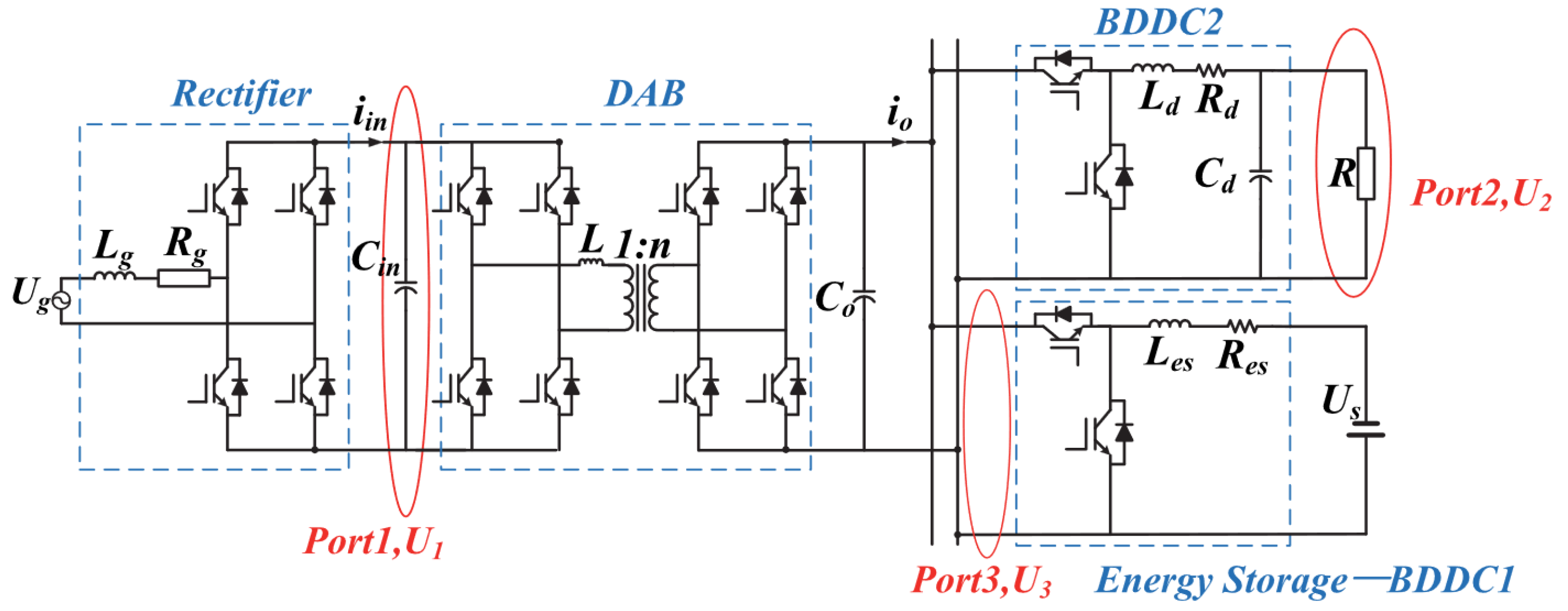
In [31], a hybrid control strategy is proposed for the SST topology represented in Figure 4.
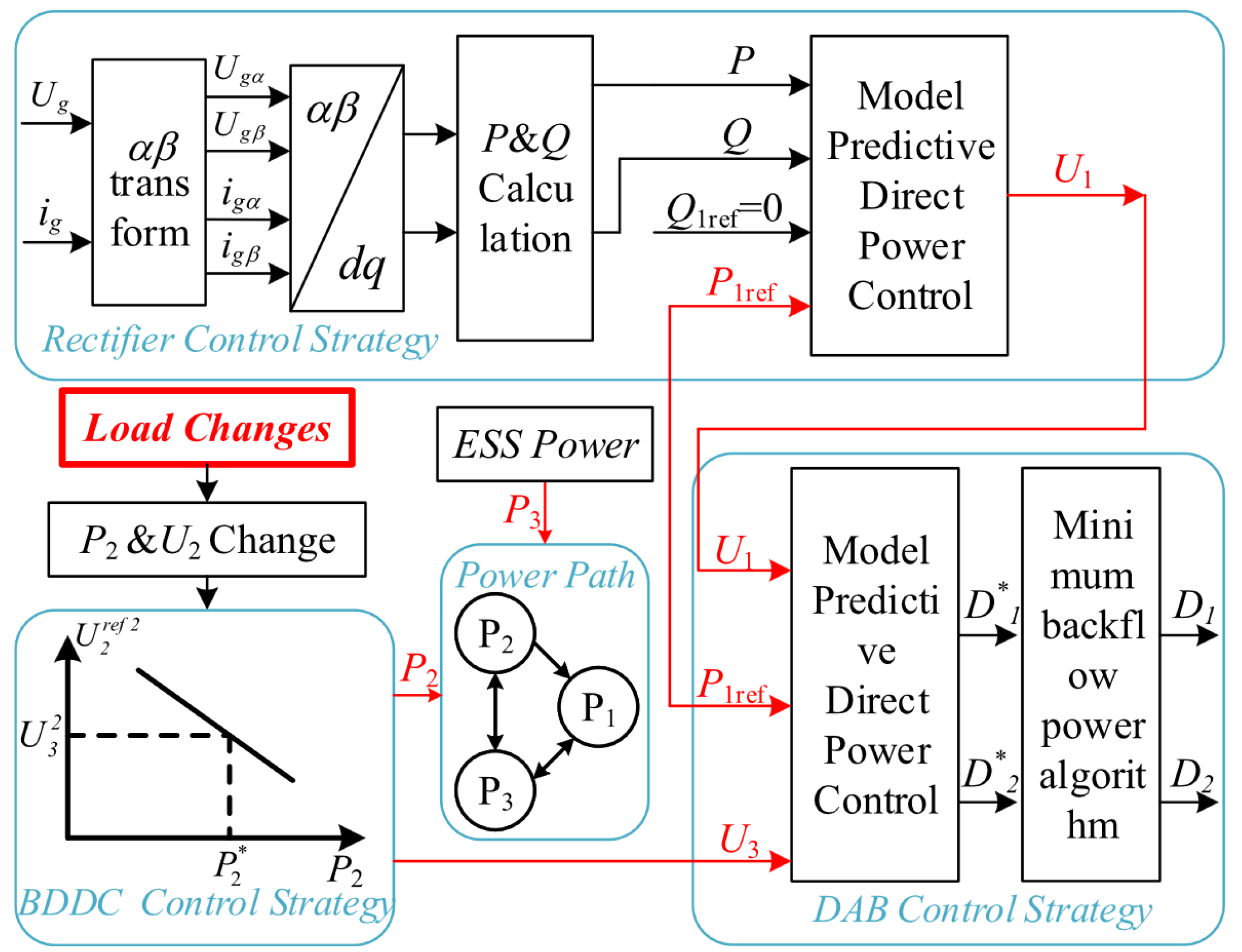
As this figure shows, the considered SST system is specially designed for AC/DC hybrid zonal microgrids, containing a 2LC rectifier, a DAB converter and also a bidirectional DC/DC converter (BDDC), that integrates an energy storage unit. The rectifier is connected to an AC microgrid, which transfers power to the DC microgrid through the DAB converter. The energy storage unit can also supply power to the load in certain situations. As shown in Figure 5, in this work, a hybrid control strategy was considered, which means that not all converters are controlled using an MPC strategy. Thus, the rectifier and DAB converter are controlled using MPC, while the BDDC control method is based on a P V 2 droop control approach. In this work, additional emphasis is provided to the control law of the DAB converter, which adopts a dual-phase shift (DPS) modulation scheme. This means that two different phase-shift values have to be computed in every control cycle: D 1 , which is the phase-shift between the two legs of one bridge and D 2 , which is the phase-shift value between the two DAB bridges. Based on the prediction model, the CCS-MPC DAB controller computes these two duty cycle values so that the required active power transfer is achieved. These values represent the inputs of a minimum backflow power algorithm, which aims to minimize the power not flowing in the intended direction (a usual problem in DAB converters). This algorithm aims to conduct adjustments in the phase-shift values, which are finally applied to the respective converter. This procedure starts with the formulation of the following cost for the DAB converter:
g D A B = | P 1 r e f P 1 [ k + 1 ] | ,
where the term P 1 r e f denotes the respective power reference and P 1 [ k + 1 ] the predicted power value, which is given by
P 1 [ k + 1 ] = n U 1 [ k ] U 3 [ k ] 8 f s L k [ 4 D 2 [ k ] ( 1 D 2 [ k ] 2 D 1 2 [ k ] ) ] .
By setting g D A B to zero, | P 1 r e f P 1 [ k + 1 ] | = 0 , the following equation is obtained,
4 D 2 [ k ] ( 1 D 2 [ k ] 2 D 1 2 [ k ] ) = 8 f s L k n U 1 [ k ] U 3 [ k ] P 1 r e f [ k + 1 ] .
This equation represents the core formula to obtain the two duty cycle values. Nonetheless, it is still combined with an equation from the minimum backflow power algorithm in order to obtain the final duty cycle values for the DAB DPS modulation scheme. As for the rectifier stage, its control scheme is also based on model predictive power control. In this case, an FCS-MPC approach is used in which the active and reactive power absorbed from the grid are directly controlled (according to the DC microgrid power needs). The possibility of power factor regulation is also enabled by this FCS-MPC strategy.
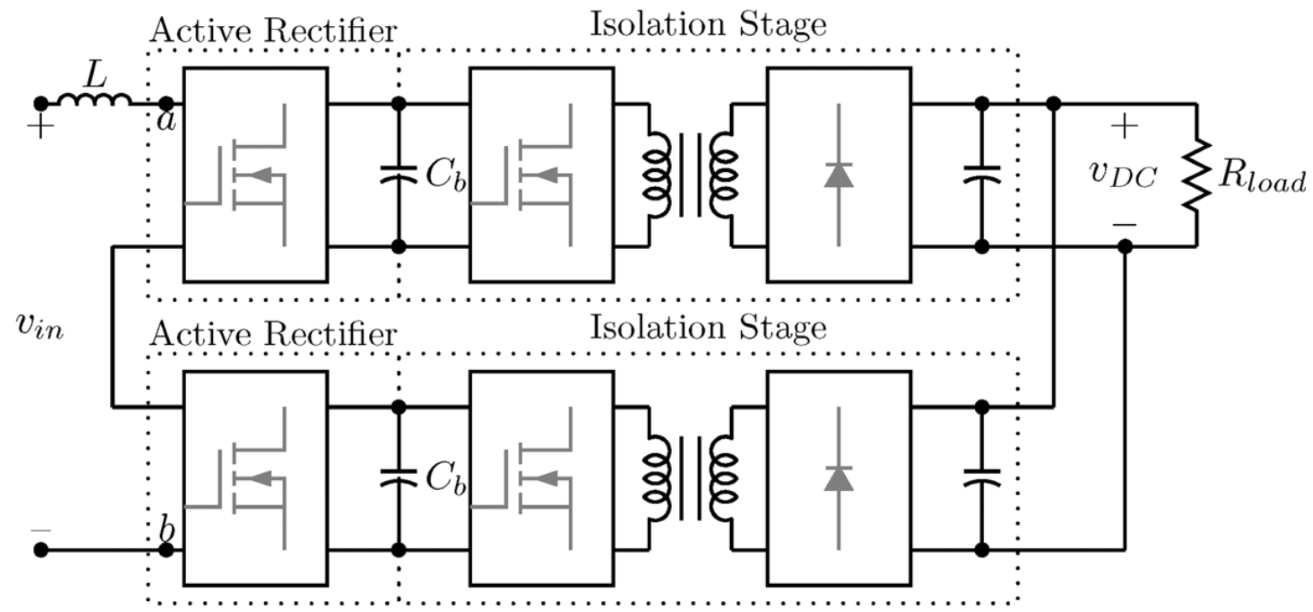
In [32], a hybrid MPC strategy is also proposed for a two-stage AC/DC SST, presented in Figure 6.
The SST topology is formed by two modules which are connected in series at the AC-side and in parallel at the DC-side. Each module is formed by a 3-level flying-capacitor converter (FCC) and an isolation stage. The isolation converter has also an FCC at the input, followed by an HFT and diode rectifier. For the detailed circuit representation please refer to [32]. Similarly to the previously discussed work, MPC is not adopted in all the SST converters. Thus, even though an FCS-MPC strategy is proposed for the AC/DC stage, the DC/DC isolation stage has no control law, with a constant duty cycle being applied to this converter. For the AC/DC stage, a state-space model was formulated and three FCS-MPC control variants were explored. These three strategies are based on the control techniques originally proposed in [38]. These strategies enable to reduce the computational burden of the control system and are designated by the authors as Control 16, Control 32, and Control 16 × 2. In Control 16, the rectifiers are only allowed to switch into the same switching state. In this case, a unique cost function is evaluated which considers input current reference tracking, and flying capacitors and DC bus voltages stability. Therefore, instead of 256 switching states to consider, only 16 control possibilities are evaluated. In Control 32, different switching states can be applied to the two active rectifiers. However, in system model prediction, it is considered that the input voltage is evenly divided between the two converters. In this case, two equal cost functions are defined for each converter. Each of these cost functions involves input reference tracking and stability of the respective flying capacitors and DC bus voltages. With this control approach, the switching states for these two converters are thus independently determined. Finally, Control 16 × 2 also enables the two rectifiers to be at different switching states, but in this case, an interleaved operation between the two converters is adopted. This means that the prediction horizon regarding each converter corresponds to half of a sampling period. In other words, the switching state for the first converter is computed until half of the sampling period, while the switching state for the other converter is computed between the middle of the sampling period and the end (beginning of the next sampling period). These three control strategies were also compared in [32], with the paper’s authors concluding that Control 16 × 2 presented the best overall performance in the used SST topology.
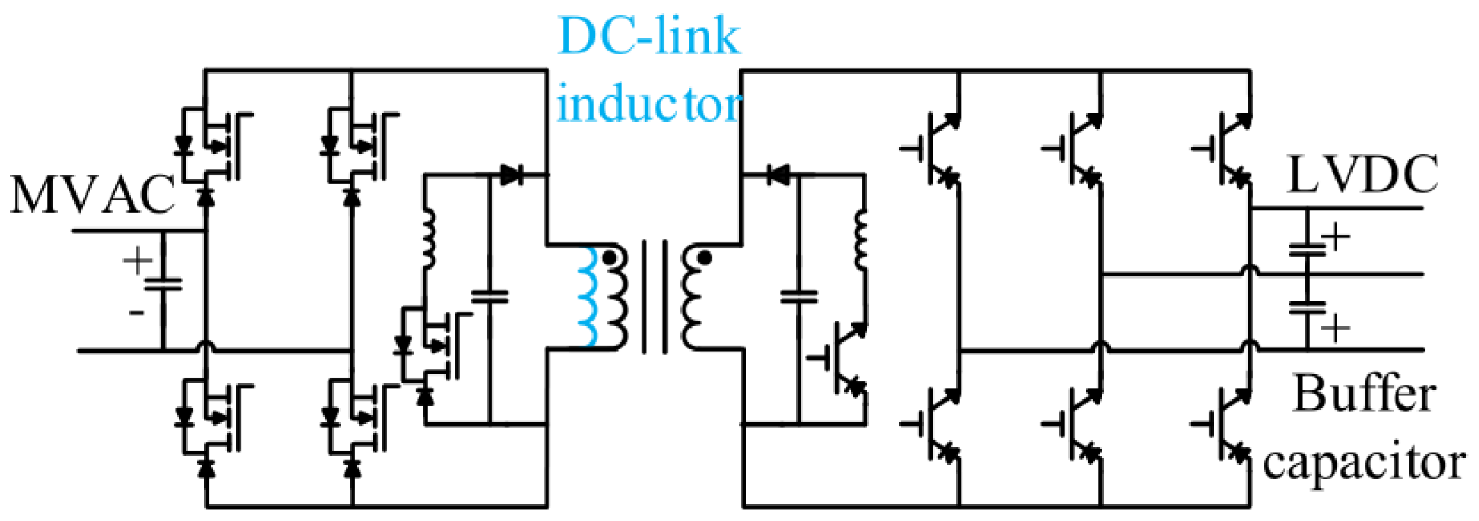
The papers discussed next use as an MPC-based method to control a very specific type of single-stage SST, designated by the authors as soft-switching SST (S4T). The S4T corresponds to a flexible topology, with different variants, that can perform AC/AC, DC/AC or even DC/DC conversion. The first topology of this type of SST was firstly proposed in [12] and is represented in Figure 7. The working principle of this type of converter is similar to a DC/DC flyback converter, in which one bridge charges the HFT magnetizing inductance while the other output bridge discharges it. In a sampling period, three main types of switching states are applied to the S4T: (a) active states, in which the transformer magnetizing current flows between the bridges and the transformer magnetizing inductance; (b) ZVS switching state, in which the magnetizing current flows through the resonant capacitors ensuring ZVS conditions (transition state between two adjacent active states); (c) resonant switching state, in which the power switches of the auxiliary resonant circuits are activated to reset the capacitor voltages for the next switching cycle [12].
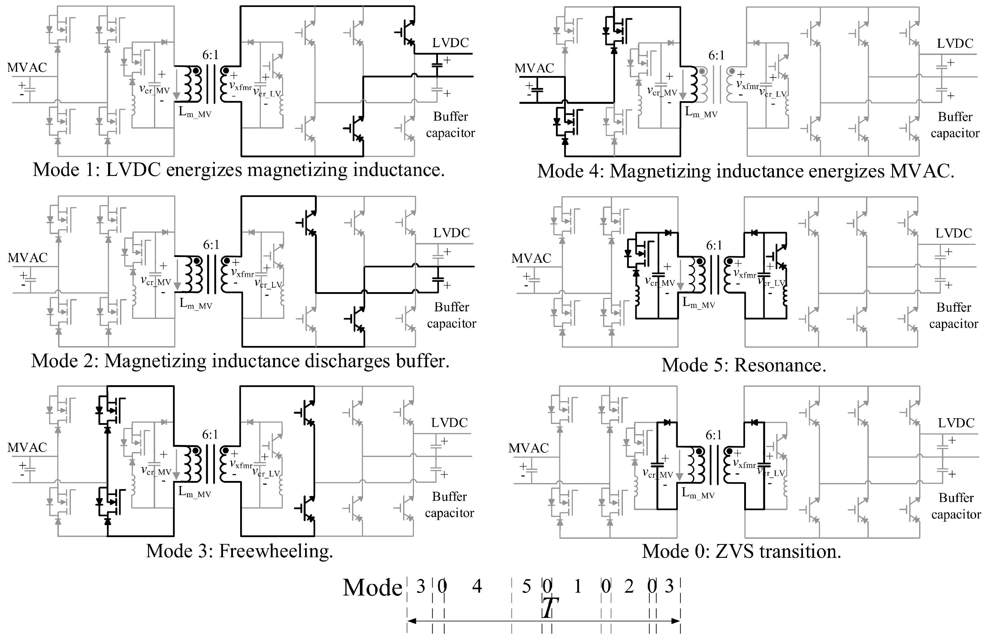
The S4T is seen as a low-inertia system in which even small disturbances can cause considerable current/voltage transient phenomena (mainly due to the absence of internal large DC bus capacitors). Conventional PI-based control methods cannot deal with transients effectively, which are very likely to happen in the S4T. For this reason, the use of MPC in this type of SST can be extremely important due to its typically fast dynamic response. The first MPC strategy for this type of SST was proposed in [39]. Since, in this reference, the considered SST topology is based on a modular configuration, it will only be discussed in Section 2.2. Nonetheless, the role of MPC initially proposed in that work was also adopted in all the other works using MPC in the S4T, including those using non-modular S4T configurations [33,34,35,40]. In all these works, the main role of MPC is to use a set of system predictive equations to calculate the dwelling times for the various types of switching states applied during a sampling period. In this way, in [33], an MPC strategy (based on work [39]) was proposed for an improved version of the S4T, shown in Figure 8. This SST performs AC/DC conversion, therefore having AC and DC ports. For a better illustration of the S4T working principle, the switching states and recommended switching sequence for this SST topology are presented in Figure 9. This figure refers to a condition in which energy flows from the DC to the AC side.
As demonstrated in this figure, the system considers 6 possible modes (switching states). In modes 1 and 2, the energy is transferred from the DC-side to the magnetizing inductance of the HFT, while in mode 4, the energy is sent from that inductance to the AC-side. However, between these switching states, a resonant (mode 5) and ZVS transition (mode 0) switching states are applied to the S4T, to achieve soft-switching. Finally, a freewheeling condition (mode 3) can also be applied to the SST. The main purpose of this mode is to ensure that the S4T operates under constant switching frequency. The switching states activation sequence is also illustrated at the bottom of Figure 9. As previously mentioned, each of these modes will have a dwelling time that is calculated using MPC. These calculations are performed in a DSP and the obtained values are sent to an FPGA. This FPGA runs a state machine and is, therefore, responsible for the power switches activation. In addition to using a slightly different topology, the main novelty of [33] in comparison with [39] relies on the magnetizing current reference calculation method. In [39], a constant value was considered for that reference regardless of the input and output SST current waveforms. Conversely, in [33], this reference is dynamically obtained in order to obtain the minimum possible magnetizing current, thus minimizing the overall SST losses.
The references [34,35] also propose MPC strategies for the SST topology presented in Figure 8. The main improvements regarding [39] are described in the following. In [34], the power flowing into the magnetizing inductance (virtual DC-link) is directly controlled, being calculated in every sampling period, to ensure fast power regulation on that link. As shown by the authors, with this approach, overshoots are effectively reduced during transient phenomena which leads to a safer and more reliable S4T operation. On the other hand, ref. [35] aims to reduce the impact of digital delays in the performance of an MPC strategy (also based on [39]), by proposing a feed-forward compensation (FFC) method for the used MPC strategy. The proposed FFC approach creates a compensation term for the S4T magnetizing current, reducing the oscillations caused by digital delays. As shown by the authors, this compensation method enabled not only to decrease the average magnetizing current but also its peak, leading to a higher S4T efficiency and the possibility of using a smaller HFT core.
Beyond the works previously discussed proposing MPC strategies for the S4T in a non-modular arrangement, there are two more studies [42,43] which also use MPC for controlling an S4T. However, these two studies essentially focus on the S4T design, and as stated by the respective paper’s authors, the MPC scheme is directly adopted from [39]. This means that no significant novelty was added to the original control scheme. For this reason, and to avoid redundancy, these two works will not be thoroughly described in this paper.

2.2. MPC in Modular SST Configurations

The existing works using MPC techniques in modular SST configurations are summarized in Table 2. These works will be discussed next, considering the following order: first, the works using MPC techniques in modular S4T topologies will be discussed [39,41,44,45,46]; then, MPC strategies in AC/DC SSTs (with intermediary DC-links) are described [8,47,48,49]; finally, the existing MPC approaches in modular AC/AC SST topologies (also with intermediary DC-links) [50,51] are also discussed.
As shown in Table 2, various works have been reported in the literature, proposing MPC-based strategies for modular S4T configurations [39,44,45,46]. As mentioned in Section 2.1, in the existing works using MPC for non-modular S4Ts, the main role of MPC is to compute the dwelling times of the different types of switching states in a sampling period. This is also valid for the modular configurations of the S4T, such as the one presented in Figure 10. This configuration performs AC/DC conversion and was considered in [41,52]. The most significant difference between the overall control schemes in the modular S4T architectures [39,44,45,46] in comparison with those adopted in the non-modular ones [33,34,35] relies on the use of a shifting mechanism denoted by the authors as Model Predictive Priority Shifting (MPPS) control. For example, the work [41] uses practically the same MPC scheme as in [34] (considers a non-modular topology), but considering this shifting mechanism. In a modular S4T, the MPPS is necessary to ensure the stability of the stacked capacitor voltages. In basic terms, in MPPS, two priority modes are defined: the steady-state and transient operation modes. In the former, the capacitors voltage unbalance is below a given threshold and, therefore, priority is shared between all the control objectives (magnetizing current reference tracking, current or voltage tracking at the non-stacked S4T side, etc., …). In the transient mode, the predictive equations (used for dwelling times calculation) are slightly re-adapted for a faster voltage balancing recovery. However, regardless of the operation mode, the role of MPC is basically the same: to obtain the switching states dwelling times.
As mentioned in Section 2.1, [39] was the first study in which an MPC strategy was proposed for this type of SST. In that work, the system was arranged to perform DC/DC conversion (as demonstrated in Figure 11), and the working principle of MPPS was firstly introduced.
In [44], the control scheme was improved with more types of switching states being evaluated and, more recently, considering controller delay compensation [45]. In [46], the control scheme was further improved and a robust MPC approach was proposed to minimize the impact caused by system parameters inaccuracy in the overall system performance. Finally, the reference [52] corresponds to the latest work of this group (using MPC in a modular S4T topology). In this work, the topology of Figure 10 was considered. This reference can be seen as an expanded version of [34,41], with some control scheme improvements (especially digital delay compensation). Furthermore, a much more complete experimental validation/analysis is also provided in this new reference.
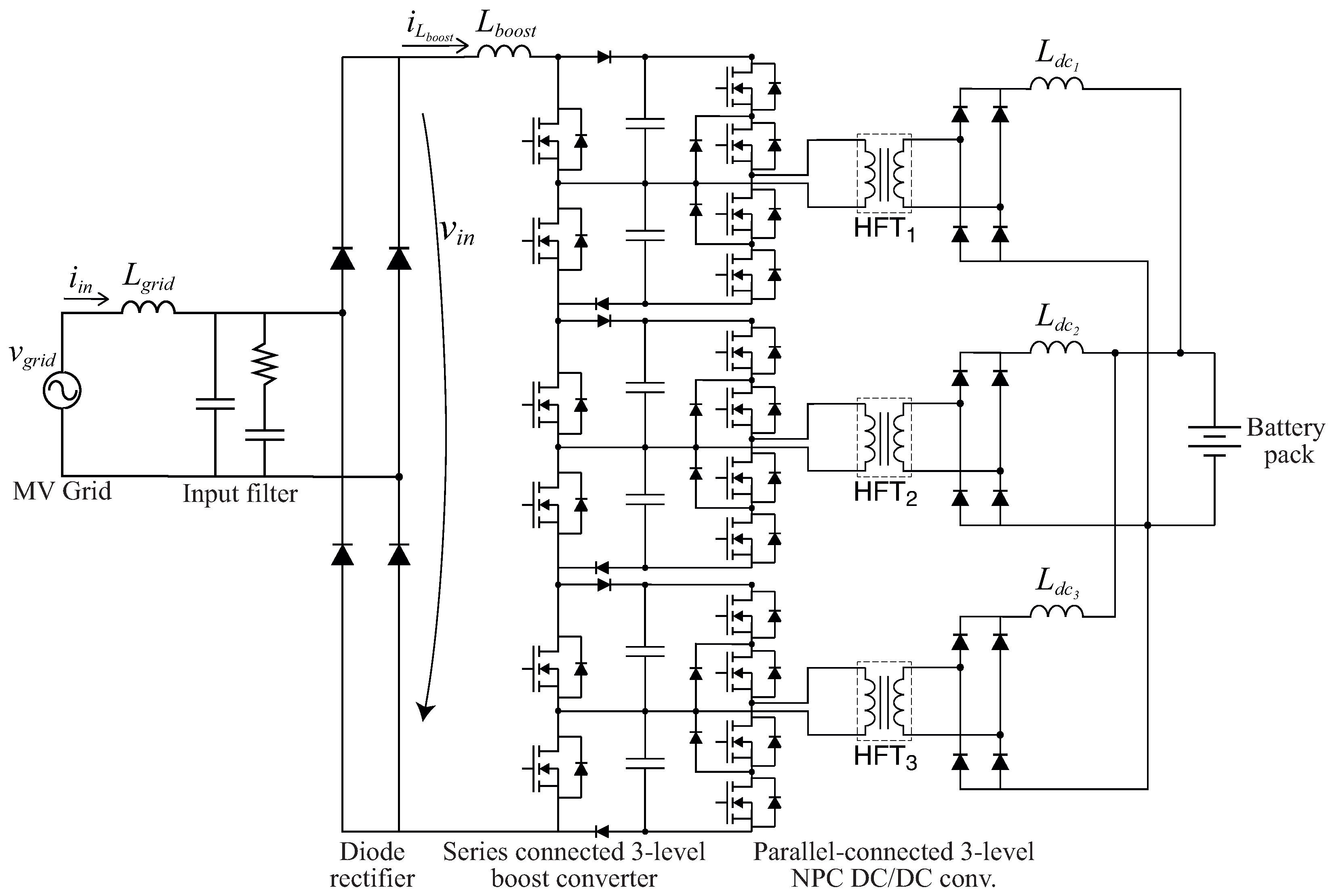
In [47], a CCS-MPC strategy was developed for a series-interleaved three-level boost (TLB) converter, integrated into the SST topology of Figure 12.
The SST uses a diode rectifier at the input, the series-interleaved TLB converter and an output parallel-connected 3LNPC-based DC/DC converter. In that study, only the control scheme of the series-interleaved TLB converter is considered. This means that the control technique for the isolated DC/DC converter is not addressed in that work, being directly adopted from [53]. The main objective of the developed MPC strategy is to track the reference of the current drawn by the TLB converter. To achieve that, based on the system prediction model a global duty cycle value is calculated for the series interleaved TLB converter using the following equation:
d [ k + 1 ] = N L b o o s t f s i a v g _ r e f [ k + 1 ] i L b o o s t [ k ] v b u s + v b u s | v i n | v b u s ,
where N is the number of power switches in this converter and f s is the switching frequency of each power switch. The current reference ( i a v g _ r e f [ k + 1 ] ) is obtained by using a conventional DC-bus voltage PI-controller, which indirectly regulates the DC-bus voltage (sum of all capacitor voltages). In addition to the overall DC-bus voltage control, the capacitor voltage balancing (in each TLB converter) should also be ensured for a correct system operation. To achieve that, N 1 additional PI-control loops are used. Each of these loops calculates an additional duty cycle term ( Δ D b a l a n c e _ i ) for the first N 1 power switches. On the other hand, for the N t h power switch, the balancing term will be given by
Δ D b a l a n c e _ N = i = 1 N 1 Δ D b a l a n c e _ i .
This ensures that these balancing terms do not interfere with the DC bus voltage control scheme. Finally, these terms are added to the previously calculated global duty cycle value, thus obtaining the final duty cycle for each power switch: d a p p l i e d _ i = d + Δ D b a l a n c e _ i , with i [ 1 , N ] . These values are then applied to the converter using an interleaved leading-triangle modulation technique.
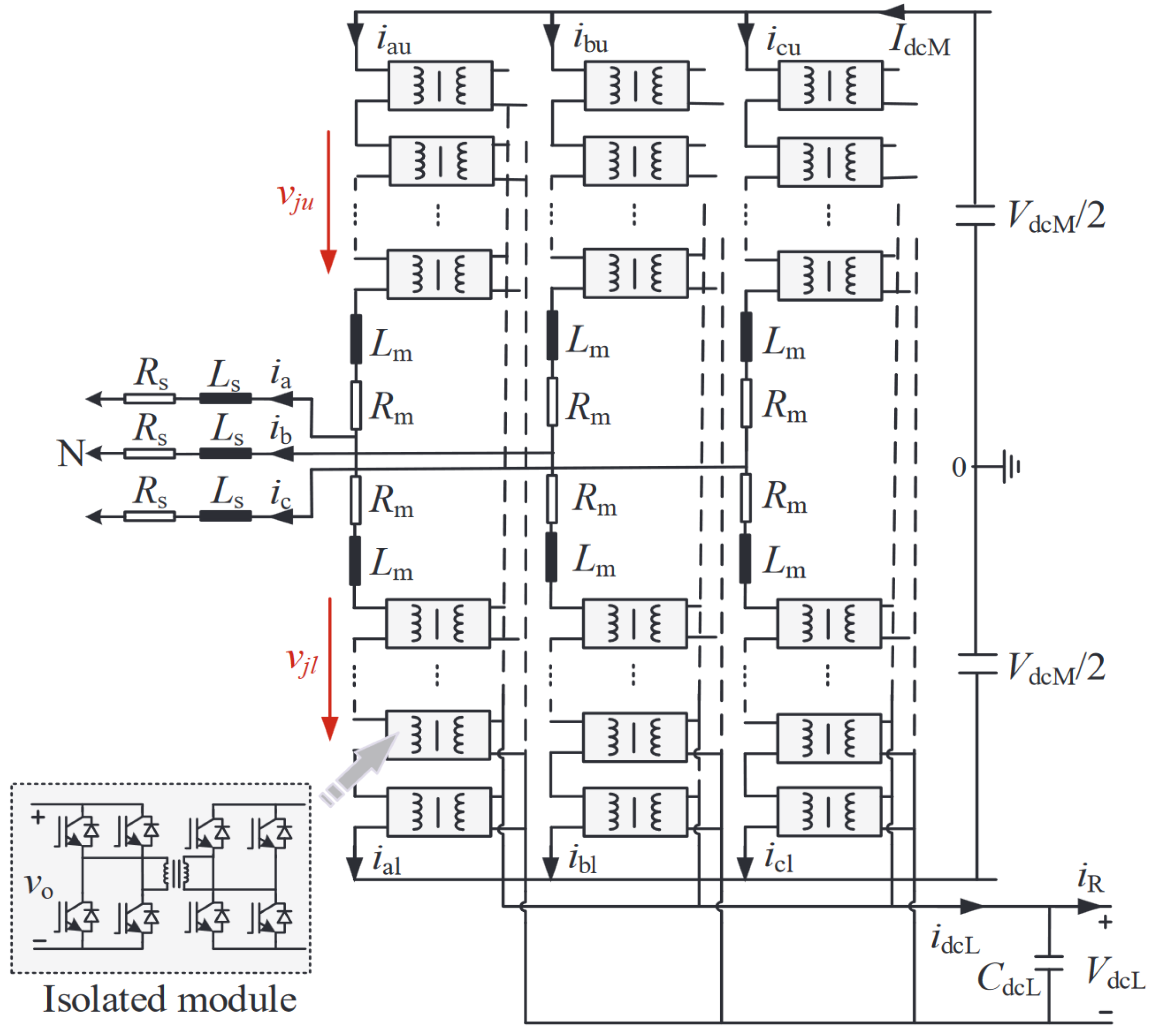
In [48], a CCS-MPC strategy was also proposed for the modular SST topology presented in Figure 13. The system consists of an isolated modular multilevel converter (I-MMC), whose cells consist of DAB converters. These cells generate an AC voltage at one side (AC-side) and a DC voltage at the other side (LVDC bus). As shown in this figure, the SST has three ports: an HVAC and HVDC port, as well as an LVDC port. The main objectives of the control system are current reference tracking in the HVAC side and LVDC bus voltage reference tracking. In this paper, the main role of the proposed CCS-MPC strategy is to calculate the optimal modulation ratios for the six I-MMC arms. These modulation ratios are then applied to the SST considering a phase-shift PWM modulation scheme, described in [54].
In [49], a control strategy based on FCS-MPC is proposed to control the rectifier stage of the modular SST topology presented in Figure 14.
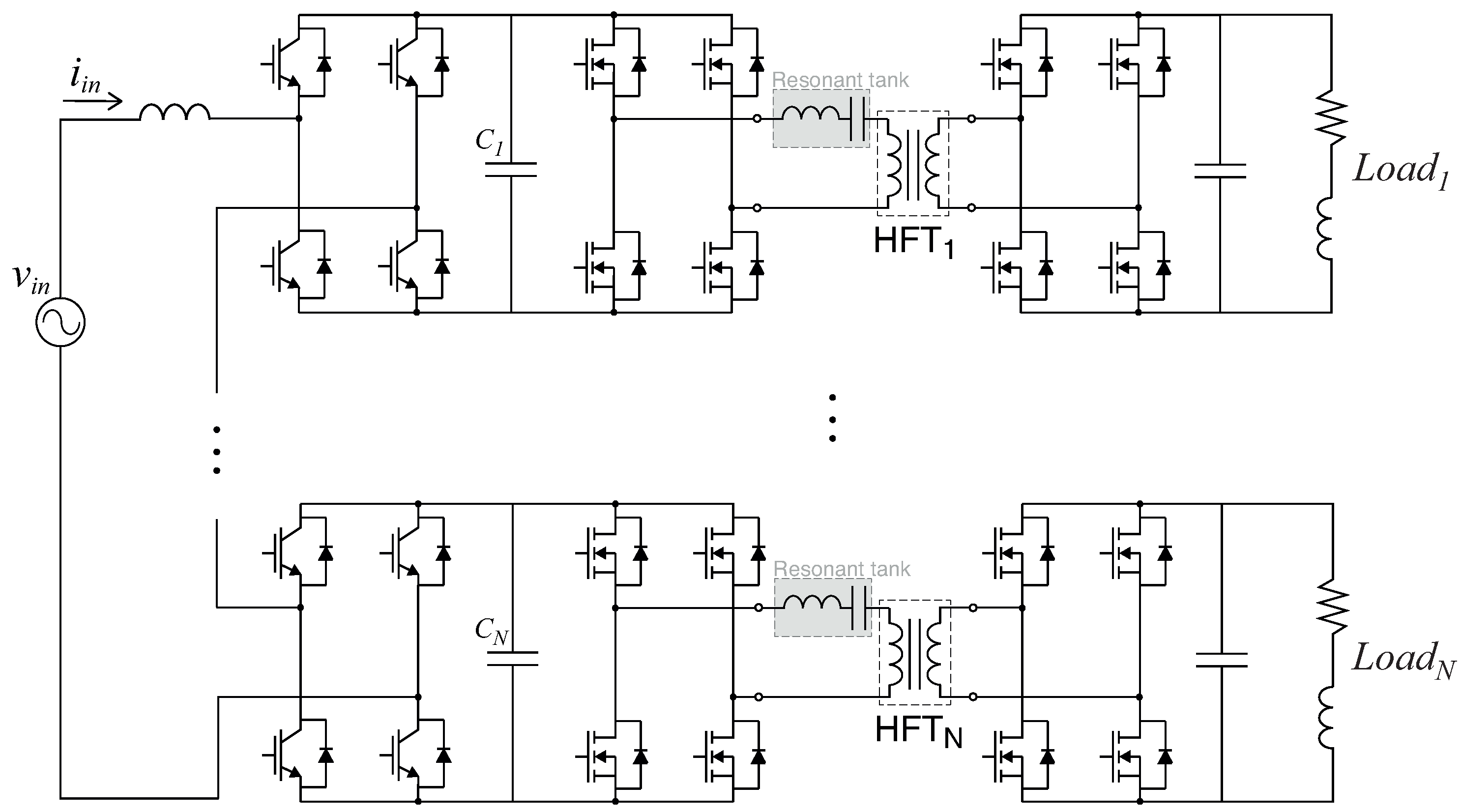
This two-stage SST is formed by a cascaded H-bridge converter (CHBC) and resonant DAB converters (linked to the output of the CHBC cells). The proposed rectifier control method is divided into two main steps, which enable to significantly reduce the computational burden of the overall control scheme. First, in order to achieve grid current reference tracking, the voltage level that the CHBC should generate at the AC-side is obtained from the FCS-MPC scheme. To achieve this, it is assumed that all capacitors are at the same voltage level ( V C ). Thus, it is also considered that the CHBC generates a discrete voltage level between N * V C and N * V C (with a step of V C ), where N denotes the number of cells. For each of these 2 N + 1 possibilities, the input current will have a different value for sample k + 1. The FCS-MPC controller is used to predict all these current values and minimize a cost function that considers the error between the predicted current and respective reference for instant k + 1. After the cost function minimization, the selected voltage level is sent to a capacitor voltage balancing algorithm. According to the grid current direction and cells capacitor voltage, this algorithm will define the switching states for each cell in order to charge/discharge their capacitors to the respective reference values (simultaneously generating the desired CHBC voltage level). As for the control principle of the DC/DC stage, no information is provided in the paper. This suggests that also in this reference, an MPC strategy that fully controls all the SST stages was not explored.
In [8], a CCS-MPC strategy is proposed for a similar SST topology, shown in Figure 15.
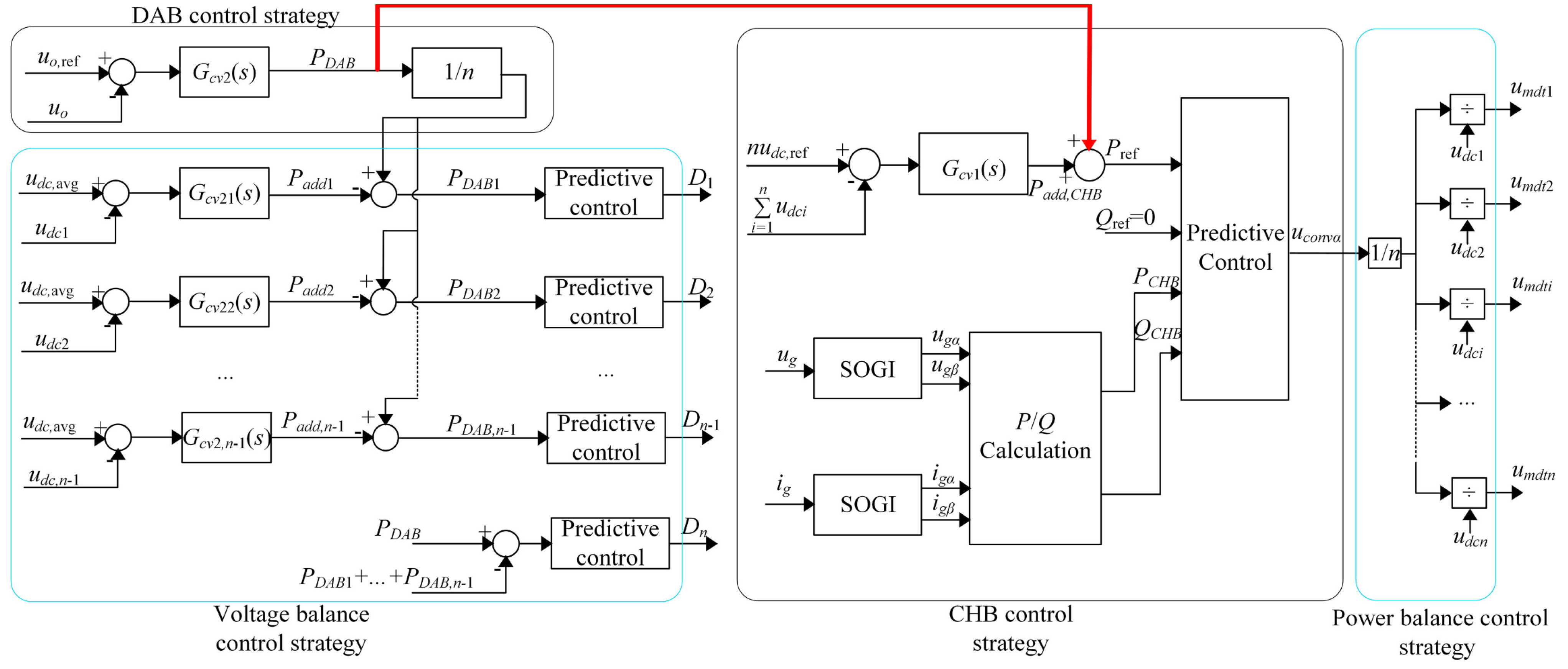
The main difference between this SST and the system considered in [49] is that in the isolation stage, conventional DAB converters are used (instead of resonant-DAB converters). In addition, these DAB converters are connected in parallel at the output, forming a unique high-power LVDC bus (instead of various low-power DC buses). As for the overall control scheme, it significantly differs from [49]. For example, a control scheme for the DC/DC stage is proposed in [8], which is also based on MPC. On the other hand, a CCS-MPC technique was considered for the input CHBC instead of an FCS-MPC approach (as used in [49]). The proposed MPC-based SST control scheme should ensure the following objectives: grid power reference tracking, LVDC bus voltage reference tracking, and balancing of the CHBC cell capacitors voltage. To achieve all these objectives, as demonstrated in Figure 16, the control scheme follows the next steps: first, the total power that needs to be supplied to the LVDC bus (to maintain its voltage in the reference value) is calculated and divided by the number of DAB converters, obtaining preliminary power references for these converters. Then, compensation power terms (obtained through conventional PI-control loops) are added to these preliminary power references, aiming to balance the CHBC capacitors voltage. Finally, the phase-shift values for the DAB converters are calculated using the respective DAB power reference value. The CHBC controller also receives the initially calculated total power value. In this controller, this term is also modified by adding a compensation term (also obtained through a PI-control loop) that enables to charge/discharge the CHBC capacitors, thus obtaining the final CHBC power reference. Finally, the optimal CHBC voltage vector can be obtained from the calculated CHBC power reference, which is then generated by a carrier phase-shifted-based modulation stage.
A brief comparison between the CHBC control strategies in [8,49] enables to understand the main differences that typically exist between an FCS-MPC strategy and a CCS-MPC strategy in modular system configurations. Firstly, please note that, in [49], the controller needs to evaluate 2 N + 1 combinations, where N denotes the number of converter cells. Thus, if this strategy is applied in a converter with 50 cells (for example), the number of combinations would be 101. This number would be even higher if a three-stage system configuration is adopted (extremely common in high-voltage applications). Beyond that, please note that this strategy already considers a control set reduction mechanism. Otherwise, if a “conventional” FCS-MPC approach technique is applied (where all the possible switching states are evaluated), the number of possible control actions would be 3 N (just for a single-phase configuration). Hence, the computational complexity of this approach directly depends on the number of converter cells. On the other hand, in the CCS-MPC approach [8], an optimal vector is analytically obtained (typically) and, therefore, the online rolling optimization is eliminated. This means that when CCS-MPC is applied to a modular converter the control complexity is practically independent from the converter complexity (number of cells). Furthermore, the problem of losing optimality is avoided in CCS-MPC as no abrupt reductions in the control set are typically needed (as in an FCS-MPC-based strategy). In addition, with a CCS-MPC technique, a non-variable switching frequency is typically obtained due to the use of a modulation stage. Having a fixed switching frequency can be very important as it means that losses/degradation can be more equally distributed between the converter cells. In addition, more concentrated harmonics spectra will be generated which is typically strongly required, as the input/output converter filters are typically designed considering a limited frequency bandwidth.
In the reference [50], a very specific type of MPC is proposed for a modular three-stage SST topology, presented in Figure 17. In fact, its principle can be seen as a combination of FCS-MPC and CCS-MPC.
The system configuration consists of two back-to-back CHBCs, connected through conventional DAB converters. In this study, the SST is used to supply an AC-load, also providing multiple internal DC-links. As for the MPC control scheme, the main objective is to regulate the AC currents at both sides. The two CHBCs have independent control but rely on the same working principle. In the proposed control scheme, only one leg of one H-bridge can be switched in each sampling period, which enables to reduce the computational complexity and the converter switching frequency. Thus, the following approach is proposed for each CHBC: considering a sampling period, one initial and one final vector are obtained using the system model prediction, as well as their respective dwelling times. Actually, the first vector of a given sampling period will correspond to the last vector of the previous sampling period. In turn, the second vector is selected between the two adjacent vectors of the first one. To select the second vector, a current-based cost function ( G ( 2 ) ) is formulated and evaluated for the two adjacent vectors, under the assumption that they can be applied during the whole sampling period. The adjacent vector that minimizes this cost function is selected (FCS-MPC part). Then, to obtain the respective vectors dwelling times, a similar cost function is computed for the first vector ( G ( 1 ) ). Finally, these times are calculated by using
t ( 1 ) = T s G ( 2 ) G ( 1 ) + G ( 2 ) ,
t ( 2 ) = T s G ( 1 ) G ( 1 ) + G ( 2 ) ,
where T s denotes the control sampling period, G ( 1 ) and G ( 2 ) the cost functions and t ( 1 ) and t ( 2 ) the vector times regarding the first and second vector. From these two expressions and considering that t ( 1 ) + t ( 2 ) = T s , it can be concluded that the vector with a lower cost function will be applied during a larger time and vice-versa. Finally, it is worth mentioning that the DAB converters use an external independent controller, proposed [55], which is not based on MPC. This controller ensures that the same voltage (or only affected by the HFTs transformation ratio) is kept on both sides of the DAB converters.
Finally, the work in [51] essentially consists of an improved version of [50]. In terms of system configuration, the main differences are: two active grids are considered at the input/output of the SST; and the single-phase SST topology of [50] is expanded to a three-phase SST. As for the control scheme, it was improved for better handling of multiple control objectives. Similarly to [50], the DC/DC stage adopts the control laws from [55] (do not rely on an MPC approach). Nevertheless, the overall control scheme presents some differences. In this work, beyond the input and output current cost functions, the SST controller now considers a new cost function, to better regulate the overall DC-link voltages (sum of DC-link capacitor voltages). At the expense of a more complex control scheme, this improved multi-objective control approach will lead to a better overall SST performance.

3. MPC in Converter Topologies Typically Used in SSTs

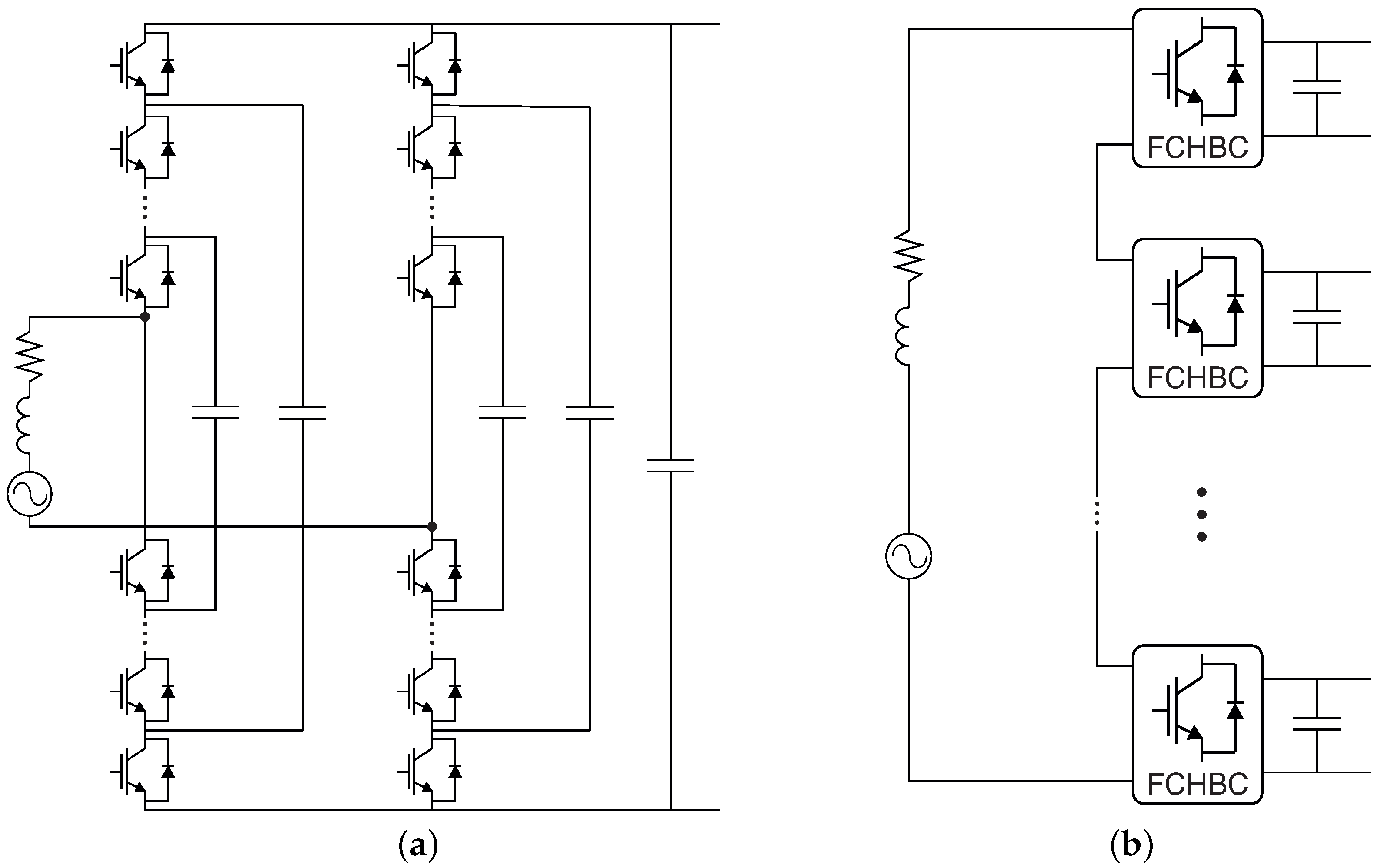
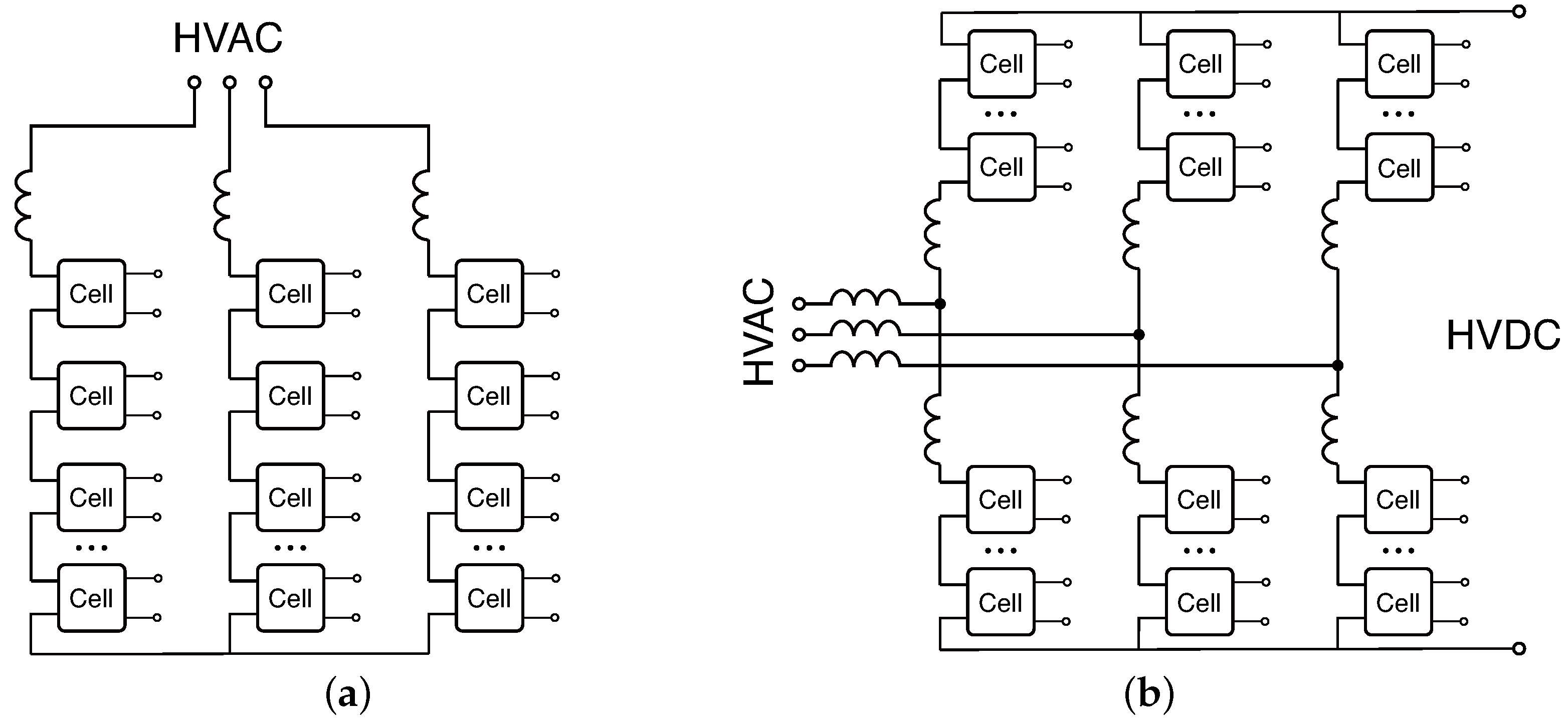
This section aims to present an overview of existing MPC strategies in some of the most promising converter topologies to be used in SSTs. Given the fact that SSTs aim to replace conventional magnetic transformers in MV and HV applications, there are converter configurations that might be more suitable for SST systems than others. For example, since an SST should support/generate an HVAC bus, the use of multi-level and/or modular AC/DC converters has been much more investigated than the use of conventional 2-level converters (due to its higher resilience and scalability). For this reason, only the authors of [56,57] state that the proposed MPC strategies target a 2LC to be used in an SST. On the other hand, the FCC, CHBC, and MMC are among the most investigated AC/DC converters for SSTs, with special emphasis on the CHBC and MMC. The FCC, CHBC, and MMC topologies are shown in Figure 18 and Figure 19.
As shown in Figure 18, the use of FCCs has been investigated both in non-modular (single converter) and modular configurations (less common). In the first case, only one output DC bus is generated while in the second case, various DC buses can be provided. As represented in Figure 19, the CHBC and MMC are based on a fully modular principle which enables these converters to generate/support a high-voltage AC bus. Nevertheless, despite the capability of the CHBC to handle a HVAC bus, its DC-links (output of each cell) will have a voltage level significantly lower than the HVAC bus voltage magnitude. This can be a severe limitation in applications that require a DC voltage level of the same order of magnitude as the HVAC bus. On the other hand, as demonstrated in Figure 19b, beyond LVDC-links, the MMC also provides an HVDC connection. It is worth mentioning that in this converter, half H-bridge cells are usually considered instead of complete H-bridges.
As for the existing MPC strategies in FCC converters, the majority of them are based on FCS-MPC [38,58,59,60,61,62,63,64], with practically no studies being reported in the literature using CCS-MPC for this type of converter.
Several FCS-MPC techniques have also been proposed for the CHBC [65,66,67,68,69,70]. Given the high complexity of this converter, the majority of these techniques have into consideration the reduction of the control computational burden by limiting the number of converter switching states in real-time. Numerous works have also been proposed for the CHBC using a CCS-MPC approach [71,72,73,74,75]. As reported in various works, modulated strategies tend to be more promising in modular converters than those based on FCS-MPC approaches. This has been motivated by the capabilities of CCS-MPC-based schemes that typically enable suppression of the exhaustive rolling optimization, non-variable switching frequency, lower sampling time to achieve equivalent steady-state performance (by virtue of a continuous control set) and others. Nevertheless, as FCS-MPC-based strategies typically have a more straightforward implementation, faster dynamic response and provide easier inclusion of system non-linearities, their use in modular converter topologies is still significantly investigated. This is valid not only for the CHBC but also for the MMC. For this converter, a huge number of MPC-based techniques have also been investigated. In this highly complex converter, these strategies aim to fulfill several control objectives, namely HVAC bus current reference tracking, cell capacitor voltage balancing and minimization of circulating currents (between converter legs and the HVDC bus). Over recent years, several strategies based on FCS-MPC approach have been proposed for the MMC [76,77,78,79,80,81], and, more recently, CCS-MPC strategies have also been investigated [82,83,84,85,86,87,88,89,90] for this converter.
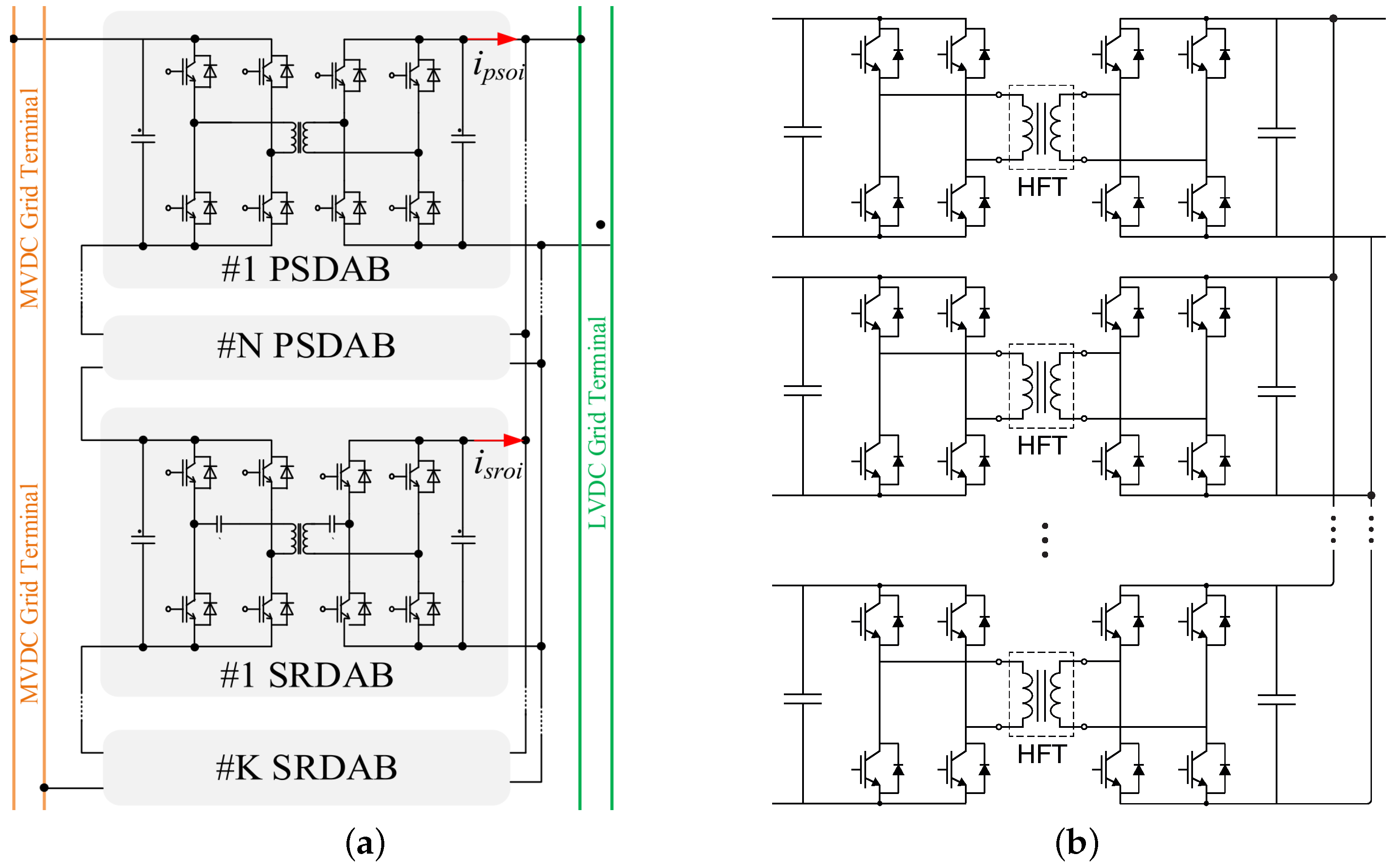
As for DC/DC converters in SSTs, the DAB converter corresponds to one of the most investigated topologies. Some works proposing MPC strategies for DAB converters can be found in the literature. However, in comparison with CHBC and MMCs, the potential of MPC in this type of converter has been significantly less explored. For DAB converters, CCS-MPC approaches are typically adopted [31,91,92,93,94]. In fact, to the best of the author’s knowledge, only in [37,95,96] strategies based on FCS-MPC have been investigated for this converter. In an SST, it is very common to find not only one but several DAB converters in a modular arrangement, as presented in Figure 20.
The configuration presented in Figure 20a is formed by input-series output-parallel (ISOP) connected DAB converters (some of them using a resonant tank). In [85,97,98,99], MPC strategies are proposed for this modular topology, being all of them based on CCS-MPC. In the configuration of Figure 20b, the DAB converters are also parallel-connected at the output, but have isolated inputs. As for MPC strategies in this topology, a CCS-MPC strategy is also proposed in [100].
Other DC/DC converter topologies have also been investigated in the framework of SSTs, including for example the MMC-based DC/DC converter topology presented in Figure 21. Actually, in [101,102,103], the authors refer to this topology as a DC/DC SST. However, according to the classification defined in the present paper, DC/DC converters are considered to be an integral part of an SST and not a complete one. As for the existing MPC strategies for this topology, even though an FCS-MPC strategy has been proposed in [104], the majority of existing MPC-based strategies are based on a CCS-MPC approach [101,102,103].
Figure 20. Some of the most investigated converter arrangements in an SST DC/DC stage. (a) ISOP resonant and non-resonant DAB converters [98], (b) Separated-input paralleled-output DAB converters [100].
Energies 15 08349 g020

4. Conclusions

This paper has presented an overview of the MPC strategies available in the literature not only for complete SST architectures but also for promising converter topologies that have been investigated in the framework of SST. As shown, different MPC approaches have been proposed for different SST topologies, based either on non-modular or modular configurations. As demonstrated in the paper, both FCS-MPC and CCS-MPC strategies have been proposed for non-modular and modular SST architectures. However, it can be concluded that more emphasis has been given to CCS-MPC approaches for the modular complete SST architectures and converter topologies. In the authors’ opinion, this has been motivated by the advantages of this type of control (CCS-MPC), which, by adopting a modulation stage, typically require a lower switching frequency than in an FCS-MPC scheme (to achieve equivalent steady-state performance), also ensuring a non-variable switching frequency. Another aspect is that, in modular topologies, the computational complexity of an FCS-MPC method typically depends on the number of used modules. This means that even using a computational reduction method, the computational complexity can still be high for converters using a large number of modules. In this regard, by avoiding the exhaustive online rolling optimization, CCS-MPC-based strategies might also be preferred. Nevertheless, FCS-MPC strategies have still been proposed for modular SST/converter topologies, showing a good overall performance, especially in transient conditions. On the other hand, FCS-MPC-based strategies typically present a much more easy and straightforward implementation than those based on CCS-MPC (mainly due to the absence of a modulation stage). Thus, it can be concluded that, besides the already proposed MPC approaches for SSTs and converter topologies (that can be used in an SST), there is still significant room to further investigate the use of different MPC approaches in the framework of SSTs.
The presented review paper represents a useful tool to introduce MPC to control engineers and researchers working in the area of SST. Furthermore, this paper will also be helpful to those who are already engaged in this field, enabling them to further improve the already existing MPC strategies in SSTs or to create new control methods for these systems, based on MPC.

Author Contributions

Conceptualization, T.O., L.C., and A.M.; validation, T.O., L.C., and A.M.; formal analysis, T.O.; investigation, T.O., L.C., A.M.; resources, T.O. and A.M.; data curation, T.O.; writing—original draft, T.O.; writing—review and editing, T.O., L.C., and A.M.; visualization, T.O.; supervision, A.M.; project administration, A.M. All authors have read and agreed to the published version of the manuscript.

Funding

This work was supported by the projects UIDB/50008/2020 and UIDP/50008/2020, both funded by Foundation for Science and Technology—Orçamento de Estado (FCT–OE). The work of Tiago Oliveira was also supported in part by FCT and in part by the European Social Fund (ESF), under the scholarship 2020.04803.BD.

Institutional Review Board Statement

Not applicable.

Informed Consent Statement

Not applicable.

Conflicts of Interest

The authors declare no conflict of interest. The funders had no role in the design of the study; in the collection, analyses, or interpretation of data; in the writing of the manuscript, or in the decision to publish the results.

Abbreviations

The following abbreviations are used in this manuscript:
2LC2-level converter
3LNPC3-level neutral point clamped
BDDCbidirectional DC/DC converter
CCS-MPCcontinuous control set model predictive control
CHBCcascaded h-bridge converter
DABdual active bridge
DPSdual phase-shift
DSPdigital signal processor
FCS-MPCfinite control set model predictive control
FCCflying-capacitor converter
FFCfeed-forward compensation
FPGAfield-programmable gate array
HFThigh-frequency transformer
HVAChigh-voltage AC
HVDChigh-voltage DC
I-MMCisolated modular multilevel converter
MDCS-MPCmoving discretized control set model predictive control
MMCmodular multilevel converter
MPCmodel predictive control
MPPSmodel predictive priority switching
LVAClow-voltage AC
LVDClow-voltage DC
PECpower electronics converter
PETpower electronics transformer
PIproportional-integral
PWMpulse width modulation
SSTsolid state transformer
S4Tsoft-switching solid state transformer
TLBthree-level boost
ZVSzero voltage switching

References

  1. Feng, J.; Chu, W.Q.; Zhang, Z.; Zhu, Z.Q. Power Electronic Transformer-Based Railway Traction Systems: Challenges and Opportunities. IEEE J. Emerg. Sel. Top. Power Electron. 2017, 5, 1237–1253. [Google Scholar] [CrossRef]
  2. Hannan, M.A.; Ker, P.J.; Lipu, M.S.H.; Choi, Z.H.; Rahman, M.S.A.; Muttaqi, K.M.; Blaabjerg, F. State of the Art of Solid-State Transformers: Advanced Topologies, Implementation Issues, Recent Progress and Improvements. IEEE Access 2020, 8, 19113–19132. [Google Scholar] [CrossRef]
  3. Huber, J.E.; Kolar, J.W. Applicability of Solid-State Transformers in Today’s and Future Distribution Grids. IEEE Trans. Smart Grid 2019, 10, 317–326. [Google Scholar] [CrossRef]
  4. Shamshuddin, M.A.; Rojas, F.; Cardenas, R.; Pereda, J.; Diaz, M.; Kennel, R. Solid State Transformers: Concepts, Classification, and Control. Energies 2020, 13, 2319. [Google Scholar] [CrossRef]
  5. Syed, I.; Khadkikar, V. Replacing the Grid Interface Transformer in Wind Energy Conversion System With Solid-State Transformer. IEEE Trans. Power Syst. 2017, 32, 2152–2160. [Google Scholar] [CrossRef]
  6. Vadakkedath Madhavan, H.; Kumar, C.; Liserre, M. An MVDC-Based Meshed Hybrid Microgrid Enabled Using Smart Transformers. IEEE Trans. Ind. Electron. 2022, 69, 3722–3731. [Google Scholar] [CrossRef]
  7. Tu, H.; Feng, H.; Srdic, S.; Lukic, S. Extreme Fast Charging of Electric Vehicles: A Technology Overview. IEEE Trans. Transp. Electrif. 2019, 5, 861–878. [Google Scholar] [CrossRef]
  8. Zhao, N.; Liu, J.; Ai, Y.; Yang, J.; Zhang, J.; You, X. Power-Linked Predictive Control Strategy for Power Electronic Traction Transformer. IEEE Trans. Power Electron. 2020, 35, 6559–6571. [Google Scholar] [CrossRef]
  9. Sarker, P.C.; Islam, M.R.; Guo, Y.; Zhu, J.; Lu, H.Y. State-of-the-Art Technologies for Development of High Frequency Transformers with Advanced Magnetic Materials. IEEE Trans. Appl. Supercond. 2019, 29, 7000111. [Google Scholar] [CrossRef] [Green Version]
  10. Xu, J.; Wang, K.; Wu, P.; Li, Z.; Liu, Y.; Li, G.; Zheng, W. FPGA-Based Submicrosecond-Level Real-Time Simulation of Solid-State Transformer With a Switching Frequency of 50 kHz. IEEE J. Emerg. Sel. Top. Power Electron. 2021, 9, 4212–4224. [Google Scholar] [CrossRef]
  11. Huber, J.E.; Kolar, J.W. Volume/weight/cost comparison of a 1MVA 10 kV/400 V solid-state against a conventional low-frequency distribution transformer. In Proceedings of the 2014 IEEE Energy Conversion Congress and Exposition (ECCE), Volume/Weight/Cost Comparison of a 1MVA 10 kV/400 V Solid-State against a Conventional Low-Frequency Distribution Transformer, Pittsburgh, PA, USA, 14–18 September 2014; pp. 4545–4552. [Google Scholar] [CrossRef]
  12. Chen, H.; Divan, D. Soft-Switching Solid-State Transformer (S4T). IEEE Trans. Power Electron. 2018, 33, 2933–2947. [Google Scholar] [CrossRef]
  13. Nair, A.C.; Fernandes, B.G. Solid-State Transformer Based Fast Charging Station for Various Categories of Electric Vehicles With Batteries of Vastly Different Ratings. IEEE Trans. Ind. Electron. 2021, 68, 10400–10411. [Google Scholar] [CrossRef]
  14. Rodriguez, J.; Garcia, C.; Mora, A.; Flores-Bahamonde, F.; Acuna, P.; Novak, M.; Zhang, Y.; Tarisciotti, L.; Davari, S.A.; Zhang, Z.; et al. Latest Advances of Model Predictive Control in Electrical Drives—Part I: Basic Concepts and Advanced Strategies. IEEE Trans. Power Electron. 2022, 37, 3927–3942. [Google Scholar] [CrossRef]
  15. Vazquez, S.; Rodriguez, J.; Rivera, M.; Franquelo, L.G.; Norambuena, M. Model Predictive Control for Power Converters and Drives: Advances and Trends. IEEE Trans. Ind. Electron. 2017, 64, 935–947. [Google Scholar] [CrossRef] [Green Version]
  16. Karamanakos, P.; Liegmann, E.; Geyer, T.; Kennel, R. Model Predictive Control of Power Electronic Systems: Methods, Results, and Challenges. IEEE Open J. Ind. Appl. 2020, 1, 95–114. [Google Scholar] [CrossRef]
  17. Pérez-Guzmán, R.E.; Rivera, M.; Wheeler, P.W. Recent Advances of Predictive Control in Power Converters. In Proceedings of the 2020 IEEE International Conference on Industrial Technology (ICIT), Buenos Aires, Argentina, 26–28 February 2020; pp. 1100–1105. [Google Scholar] [CrossRef]
  18. Lim, C.S.; Lee, S.S.; Cassandra Wong, Y.C.; Nutkani, I.U.; Goh, H.H. Comparison of Current Control Strategies Based on FCS-MPC and D-PI-PWM Control for Actively Damped VSCs With LCL-Filters. IEEE Access 2019, 7, 112410–112423. [Google Scholar] [CrossRef]
  19. Caseiro, L.M.A.; Mendes, A.M.S.; Cruz, S.M.A. Cooperative and Dynamically Weighted Model Predictive Control of a 3-Level Uninterruptible Power Supply With Improved Performance and Dynamic Response. IEEE Trans. Ind. Electron. 2020, 67, 4934–4945. [Google Scholar] [CrossRef]
  20. Oliveira, T.; Caseiro, L.; Mendes, A.; Cruz, S.; Perdigão, M. Model Predictive Control for Paralleled Uninterruptible Power Supplies with an Additional Inverter Leg for Load-Side Neutral Connection. Energies 2021, 14, 2270. [Google Scholar] [CrossRef]
  21. Abu-Siada, A.; Budiri, J.; Abdou, A.F. Solid State Transformers Topologies, Controllers, and Applications: State-of-the-Art Literature Review. Electronics 2018, 7, 298. [Google Scholar] [CrossRef] [Green Version]
  22. Saleh, S.A.M.; Richard, C.; Onge, X.F.S.; McDonald, K.M.; Ozkop, E.; Chang, L.; Alsayid, B. Solid-State Transformers for Distribution Systems–Part I: Technology and Construction. IEEE Trans. Ind. Appl. 2019, 55, 4524–4535. [Google Scholar] [CrossRef]
  23. Mishra, D.K.; Ghadi, M.J.; Li, L.; Hossain, M.J.; Zhang, J.; Ray, P.K.; Mohanty, A. A review on solid-state transformer: A breakthrough technology for future smart distribution grids. Int. J. Electr. Power Energy Syst. 2021, 133, 107255. [Google Scholar] [CrossRef]
  24. Liu, Y.; Liu, Y.; Abu-Rub, H.; Ge, B. Model predictive control of matrix converter based solid state transformer. In Proceedings of the 2016 IEEE International Conference on Industrial Technology (ICIT), Taipei, Taiwan, 14–17 March 2016; pp. 1248–1253. [Google Scholar] [CrossRef]
  25. Liu, Y.; Liu, Y.; Abu-Rub, H.; Ge, B.; Balog, R.S.; Xue, Y. Model predictive control of a matrix-converter based solid state transformer for utility grid interaction. In Proceedings of the 2016 IEEE Energy Conversion Congress and Exposition (ECCE), Milwaukee, WI, USA, 18–22 September 2016; pp. 1–6. [Google Scholar] [CrossRef]
  26. Liu, Y.; Wang, W.; Liu, Y.; Bayhan, S. Real-time implementation of finite control set model predictive control for matrix converter based solid state transformer. Int. J. Hydrogen Energy 2017, 42, 17976–17983. [Google Scholar] [CrossRef]
  27. Liu, Y.; Liu, Y.; Ge, B.; Abu-Rub, H. Interactive Grid Interfacing System by Matrix-Converter-Based Solid State Transformer With Model Predictive Control. IEEE Trans. Ind. Inform. 2020, 16, 2533–2541. [Google Scholar] [CrossRef]
  28. Raaed Faleh Hassan, D. Design and software implementation of solid state transformer. Int. J. Eng. Technol. 2018, 7, 1776. [Google Scholar] [CrossRef] [Green Version]
  29. Buticchi, G.; Tarisciotti, L.; Wheeler, P.; Shao, S.; Chen, L. Current and Voltage Model Predictive Control for a Three-Stage Smart Transformer. In Proceedings of the 2021 IEEE 30th International Symposium on Industrial Electronics (ISIE), Kyoto, Japan, 20–23 June 2021; pp. 1–5. [Google Scholar] [CrossRef]
  30. Tarisciotti, L.; Buticchi, G.; De Carne, G.; Yang, J.; Gu, C.; Wheeler, P. Unified Cost Function Model Predictive Control for a three-stage Smart Transformer. In Proceedings of the 2021 IEEE Energy Conversion Congress and Exposition (ECCE), Vancouver, BC, Canada, 10–14 October 2021; pp. 3468–3475. [Google Scholar] [CrossRef]
  31. Sun, Q.; Li, Y.; Ma, D.; Zhang, Y.; Qin, D. Model Predictive Direct Power Control of Three-Port Solid-State Transformer for Hybrid AC/DC Zonal Microgrid Applications. IEEE Trans. Power Deliv. 2022, 37, 528–538. [Google Scholar] [CrossRef]
  32. du Toit, D.; Mouton, H.d.T.; Kennel, R.; Stolze, P. Predictive Control of Series Stacked Flying-Capacitor Active Rectifiers. IEEE Trans. Ind. Inform. 2013, 9, 697–707. [Google Scholar] [CrossRef]
  33. Zheng, L.; Han, X.; Prasad Kandula, R.; Divan, D. Dynamic DC-Link Current Minimization Control to Improve Current-Source Solid-State Transformer Efficiency. In Proceedings of the 2020 IEEE Energy Conversion Congress and Exposition (ECCE), Detroit, MI, USA, 11–15 October 2020; pp. 1636–1641. [Google Scholar] [CrossRef]
  34. Zheng, L.; Prasad Kandula, R.; Divan, D. Predictive Direct DC-Link Control for Active Power Decoupling of A Single-Phase Reduced DC-Link MV Solid-State Transformer. In Proceedings of the 2020 IEEE Energy Conversion Congress and Exposition (ECCE), Detroit, MI, USA, 11–15 October 2020; pp. 4124–4129. [Google Scholar] [CrossRef]
  35. An, Z.; Kandula, R.P.; Divan, D. Feed-Forward Compensation for Model Predictive Control in Tri-port Current-Source Medium-Voltage String Inverters for PV-Plus-Storage Farms. In Proceedings of the 2021 IEEE Energy Conversion Congress and Exposition (ECCE), Vancouver, BC, Canada, 10–14 October 2021; pp. 3430–3435. [Google Scholar] [CrossRef]
  36. Xiao, Q.; Chen, L.; Jia, H.; Wheeler, P.W.; Dragičević, T. Model Predictive Control for Dual Active Bridge in Naval DC Microgrids Supplying Pulsed Power Loads Featuring Fast Transition and Online Transformer Current Minimization. IEEE Trans. Ind. Electron. 2020, 67, 5197–5203. [Google Scholar] [CrossRef]
  37. Tarisciotti, L.; Chen, L.; Shao, S.; Dragičević, T.; Wheeler, P.; Zanchetta, P. Finite Control Set Model Predictive Control for Dual Active Bridge Converter. IEEE Trans. Ind. Appl. 2022, 58, 2155–2165. [Google Scholar] [CrossRef]
  38. du Toit, D.; Mouton, T.; Kennel, R.; Stolze, P. Predictive control for a series stacked flying-capacitor active rectifier. In Proceedings of the 2011 6th IEEE Conference on Industrial Electronics and Applications, Beijing, China, 21–23 June 2011; pp. 1809–1814. [Google Scholar] [CrossRef]
  39. Zheng, L.; Kandula, R.P.; Kandasamy, K.; Divan, D. Fast Dynamic Control of Stacked Low Inertia Converters. In Proceedings of the 2018 IEEE Energy Conversion Congress and Exposition (ECCE), Portland, OR, USA, 23–27 September 2018; pp. 3126–3133. [Google Scholar] [CrossRef]
  40. Yan, D.; Marellapudi, A.; Kandula, R.P.; Divan, D. Oversampling Multi-Variable Control for Soft-Switching Solid-State Transformer. In Proceedings of the 2021 IEEE Energy Conversion Congress and Exposition (ECCE), Vancouver, BC, Canada, 10–14 October 2021; pp. 3476–3483. [Google Scholar] [CrossRef]
  41. Zheng, L.; Han, X.; Kandula, R.P.; Kandasamy, K.; Saeedifard, M.; Divan, D. 7.2 kV Three-Port Single-Phase Single-Stage Modular Soft-Switching Solid-State Transformer with Active Power Decoupling and Reduced DC-Link. In Proceedings of the 2020 IEEE Applied Power Electronics Conference and Exposition (APEC), New Orleans, LA, USA, 15–19 March 2020; pp. 1575–1581. [Google Scholar] [CrossRef]
  42. Zheng, L.; Kandula, R.P.; Divan, D. Soft-Switching Solid-State Transformer With Reduced Conduction Loss. IEEE Trans. Power Electron. 2021, 36, 5236–5249. [Google Scholar] [CrossRef]
  43. Zheng, L.; Kandula, R.P.; Divan, D. New Single-Stage Soft-Switching Solid-State Transformer with Reduced Conduction Loss and Minimal Auxiliary Switch. In Proceedings of the 2020 IEEE Applied Power Electronics Conference and Exposition (APEC), New Orleans, LA, USA, 15–19 March 2020; pp. 560–567. [Google Scholar] [CrossRef]
  44. Zheng, L.; Han, X.; An, Z.; Kandula, R.P.; Kandasamy, K.; Saeedifard, M.; Divan, D. SiC-Based 5-kV Universal Modular Soft-Switching Solid-State Transformer (M-S4T) for Medium-Voltage DC Microgrids and Distribution Grids. IEEE Trans. Power Electron. 2021, 36, 11326–11343. [Google Scholar] [CrossRef]
  45. Zheng, L.; Kandula, R.P.; Kandasamy, K.; Divan, D. Stacked Low-Inertia Converter or Solid-State Transformer: Modeling and Model Predictive Priority-Shifting Control for Voltage Balance. IEEE Trans. Power Electron. 2021, 36, 8934–8952. [Google Scholar] [CrossRef]
  46. Zheng, L.; Kandula, R.P.; Divan, D. Robust Predictive Control for Modular Solid-State Transformer With Reduced DC Link and Parameter Mismatch. IEEE Trans. Power Electron. 2021, 36, 14295–14311. [Google Scholar] [CrossRef]
  47. Liang, X.; Zhang, C.; Srdic, S.; Lukic, S.M. Predictive Control of a Series-Interleaved Multicell Three-Level Boost Power-Factor-Correction Converter. IEEE Trans. Power Electron. 2018, 33, 8948–8960. [Google Scholar] [CrossRef]
  48. Kong, D.; Zhang, Z.; Liu, C.; Tian, W.; Gao, X.; Kennel, R. Modulated Model Predictive Control of Power Electronics Transformer Based on Isolated Modular Multilevel Converter. In Proceedings of the 2021 IEEE International Conference on Predictive Control of Electrical Drives and Power Electronics (PRECEDE), Jinan, China, 20–22 November 2021; pp. 831–835. [Google Scholar] [CrossRef]
  49. Haghgooyi, P.; Khaburi, D.A.; Khosravi, M.; Heshmatian, S.; Rodriguez, J.; Peñailillo, C.G. A Hybrid Control Method Based on Model Predictive Control for Controlling the Rectifier Stage of Power Electronic Transformers. In Proceedings of the 2019 IEEE International Symposium on Predictive Control of Electrical Drives and Power Electronics (PRECEDE), Quanzhou, China, 31 May–2 June 2019; pp. 1–6. [Google Scholar] [CrossRef]
  50. Tarisciotti, L.; Zanchetta, P.; Watson, A.; Bifaretti, S.; Clare, J.C. Modulated Model Predictive Control for a Seven-Level Cascaded H-Bridge Back-to-Back Converter. IEEE Trans. Ind. Electron. 2014, 61, 5375–5383. [Google Scholar] [CrossRef]
  51. Tarisciotti, L.; Zanchetta, P.; Watson, A.; Wheeler, P.; Clare, J.C.; Bifaretti, S. Multiobjective Modulated Model Predictive Control for a Multilevel Solid-State Transformer. IEEE Trans. Ind. Appl. 2015, 51, 4051–4060. [Google Scholar] [CrossRef]
  52. Zheng, L.; Kandula, R.P.; Divan, D. Predictive Direct DC-Link Control for 7.2 kV Three-Port Low-Inertia Solid-State Transformer With Active Power Decoupling. IEEE Trans. Power Electron. 2022, 37, 11673–11685. [Google Scholar] [CrossRef]
  53. Srdic, S.; Liang, X.; Zhang, C.; Yu, W.; Lukic, S. A SiC-based high-performance medium-voltage fast charger for plug-in electric vehicles. In Proceedings of the 2016 IEEE Energy Conversion Congress and Exposition (ECCE), Milwaukee, WI, USA, 18–22 September 2016. [Google Scholar] [CrossRef]
  54. Liu, C.; Liu, C.; Cai, G.; Ying, H.; Zhang, Z.; Shan, R.; Pei, Z.; Song, X. An Isolated Modular Multilevel Converter (I-M2C) Topology Based on High-Frequency Link (HFL) Concept. IEEE Trans. Power Electron. 2020, 35, 1576–1588. [Google Scholar] [CrossRef]
  55. Watson, A.J.; Wheeler, P.W.; Clare, J.C. Field programmable gate array based control of Dual Active Bridge DC/DC Converter for the UNIFLEX-PM project. In Proceedings of the 2011 14th European Conference on Power Electronics and Applications, Birmingham, UK, 30 August–1 September 2011; pp. 1–9. [Google Scholar]
  56. Zan, W.; Chai, M.; Bhandari, S.; Panda, S.K. Advanced Model Predictive Control Methods for Bidirectional Three-Phase Two-Level Converter for Solid State Transformers. In Proceedings of the 2018 IEEE Innovative Smart Grid Technologies—Asia (ISGT Asia), Singapore, 22–25 May 2018; pp. 244–249. [Google Scholar] [CrossRef]
  57. Liu, B.; Zha, Y.; Zhang, T.; Chen, S. Predictive direct power control for rectifier stage of solid state transformer. In Proceedings of the 2016 12th World Congress on Intelligent Control and Automation (WCICA), Guilin, China, 12–15 June 2016; pp. 201–204. [Google Scholar] [CrossRef]
  58. Kim, S.H.; Kim, R.Y.; Kim, S.I. Generalized Model Predictive Control Method for Single-Phase N-Level Flying Capacitor Multilevel Rectifiers for Solid State Transformer. IEEE Trans. Ind. Appl. 2019, 55, 7505–7514. [Google Scholar] [CrossRef]
  59. Park, D.H.; Kim, R.y. Model Predictive Control with Reduced Computation for N-cell Cascaded Flying Capacitor H-Bridge Converter in Solid-State Transformer. In Proceedings of the 2022 International Power Electronics Conference (IPEC—Himeji 2022—ECCE Asia), Himeji, Japan, 15–19 May 2022; pp. 720–724. [Google Scholar] [CrossRef]
  60. Lezana, P.; Norambuena, M.; Aguilera, R.P. Dual-Stage Control Strategy for a Flying Capacitor Converter Based on Model Predictive and Linear Controllers. IEEE Trans. Ind. Inform. 2022, 18, 2203–2212. [Google Scholar] [CrossRef]
  61. Park, D.H.; Tahir, H.; Lee, J.D.; Kim, R.Y. Hierarchical Single-Objective Model Predictive Control With Reduced Computational Burden in Cascaded H-Bridge Converter Based on 3-Level Flying Capacitor Unit Cell. IEEE Access 2022, 10, 54730–54741. [Google Scholar] [CrossRef]
  62. Garcia, C.; Mohammadinodoushan, M.; Yaramasu, V.; Norambuena, M.; Davari, S.A.; Zhang, Z.; Khaburi, D.A.; Rodriguez, J. FCS-MPC Based Pre-Filtering Stage for Computational Efficiency in a Flying Capacitor Converter. IEEE Access 2021, 9, 111039–111049. [Google Scholar] [CrossRef]
  63. Kim, S.H.; Jang, Y.H.; Kim, R.Y. Modeling and Hierarchical Structure Based Model Predictive Control of Cascaded Flying Capacitor Bridge Multilevel Converter for Active Front-End Rectifier in Solid-State Transformer. IEEE Trans. Ind. Electron. 2019, 66, 6560–6569. [Google Scholar] [CrossRef]
  64. Jang, Y.H.; Kim, S.H.; Kim, R.Y. Model Predictive Control for Cascaded Flying Capacitor Cell Multilevel Converter. In Proceedings of the 2018 Asian Conference on Energy, Power and Transportation Electrification (ACEPT), Singapore, 30 October–2 November 2018; pp. 1–5. [Google Scholar] [CrossRef]
  65. He, T.; Wu, M.; Lu, D.D.C.; Song, K.; Zhu, J. Model Predictive Sliding Control for Cascaded H-Bridge Multilevel Converters With Dynamic Current Reference Tracking. IEEE J. Emerg. Sel. Top. Power Electron. 2022, 10, 1409–1421. [Google Scholar] [CrossRef]
  66. Baier, C.R.; Ramirez, R.O.; Marciel, E.I.; Hernandez, J.C.; Melin, P.E.; Espinosa, E.E. FCS-MPC Without Steady-State Error Applied to a Grid-Connected Cascaded H-Bridge Multilevel Inverter. IEEE Trans. Power Electron. 2021, 36, 11785–11799. [Google Scholar] [CrossRef]
  67. Ramírez, R.O.; Baier, C.R.; Villarroel, F.; Espinoza, J.R.; Pou, J.; Rodríguez, J. A Hybrid FCS-MPC With Low and Fixed Switching Frequency Without Steady-State Error Applied to a Grid-Connected CHB Inverter. IEEE Access 2020, 8, 223637–223651. [Google Scholar] [CrossRef]
  68. Ramírez, R.O.; Baier, C.R.; Espinoza, J.; Villarroel, F. Finite Control Set MPC with Fixed Switching Frequency Applied to a Grid Connected Single-Phase Cascade H-Bridge Inverter. Energies 2020, 13, 5475. [Google Scholar] [CrossRef]
  69. Chai, M.; Gorla, N.B.Y.; Panda, S.K. Improved Performance With Dual-Model Predictive Control for Cascaded H-Bridge Multilevel Converter. IEEE Trans. Ind. Appl. 2019, 55, 4886–4899. [Google Scholar] [CrossRef]
  70. Nasiri, M.R.; Farhangi, S.; Rodriguez, J. Model Predictive Control of a Multilevel CHB STATCOM in Wind Farm Application Using Diophantine Equations. IEEE Trans. Ind. Electron. 2019, 66, 1213–1223. [Google Scholar] [CrossRef]
  71. Xiao, Q.; Jin, Y.; Jia, H.; Mu, Y.; Ji, Y.; Teodorescu, R.; Blaabjerg, F. Modulated Model Predictive Control for Multilevel Cascaded H-Bridge Converter-Based Static Synchronous Compensator. IEEE Trans. Ind. Electron. 2022, 69, 1091–1102. [Google Scholar] [CrossRef]
  72. He, T.; Wu, M.; Aguilera, R.P.; Lu, D.D.C.; Liu, Q.; Vazquez, S. Low Computational Burden Model Predictive Control for Single-Phase Cascaded H-Bridge Converters Without Weighting Factor, (early access). IEEE Trans. Ind. Electron. 2022. [Google Scholar] [CrossRef]
  73. Cuzmar, R.H.; Pereda, J.; Aguilera, R.P. Phase-Shifted Model Predictive Control to Achieve Power Balance of CHB Converters for Large-Scale Photovoltaic Integration. IEEE Trans. Ind. Electron. 2021, 68, 9619–9629. [Google Scholar] [CrossRef]
  74. Gómez, P.J.; Galván, L.; Galván, E.; Carrasco, J.M.; Vázquez, S. Optimal Switching Sequence Model Predictive Control for Single-Phase Cascaded H-Bridge. In Proceedings of the IECON 2021—47th Annual Conference of the IEEE Industrial Electronics Society, Toronto, ON, Canada, 13–16 October 2021; pp. 1–6. [Google Scholar] [CrossRef]
  75. Zhao, X.; Xu, G.; Wang, L.; Yuan, Y.; Zhou, J. A Novel Clustered Voltage Balance for Cascaded H-Bridge STATCOM with CCS-MPC. In Proceedings of the 2021 IEEE 4th International Electrical and Energy Conference (CIEEC), Wuhan, China, 28–30 May 2021; pp. 1–6. [Google Scholar] [CrossRef]
  76. Yang, X.; Liu, H.; Mi, Y.; Ji, L.; Wang, Y.; Fu, Y. Improved two-stage model predictive control method for modular multi-level converter. IET Electr. Power Appl. 2021, 15, 1205–1216. [Google Scholar] [CrossRef]
  77. Wu, W.; Wang, D.; Peng, Z.; Liu, X. Model predictive direct power control for modular multilevel converter under unbalanced conditions with power compensation and circulating current reduction. ISA Trans. 2020, 106, 318–329. [Google Scholar] [CrossRef] [PubMed]
  78. Guo, P.; He, Z.; Yue, Y.; Xu, Q.; Huang, X.; Chen, Y.; Luo, A. A Novel Two-Stage Model Predictive Control for Modular Multilevel Converter With Reduced Computation. IEEE Trans. Ind. Electron. 2019, 66, 2410–2422. [Google Scholar] [CrossRef]
  79. Liu, X.; Qiu, L.; Wu, W.; Ma, J.; Fang, Y.; Peng, Z.; Wang, D. Predictor-Based Neural Network Finite-Set Predictive Control for Modular Multilevel Converter. IEEE Trans. Ind. Electron. 2021, 68, 11621–11627. [Google Scholar] [CrossRef]
  80. Chen, X.; Liu, J.; Song, S.; Ouyang, S.; Wu, H.; Yang, Y. Modified Increased-Level Model Predictive Control Methods With Reduced Computation Load for Modular Multilevel Converter. IEEE Trans. Power Electron. 2019, 34, 7310–7325. [Google Scholar] [CrossRef]
  81. Li, M.; Chang, X.; Dong, N.; Liu, S.; Yang, H.; Zhao, R. Arm-Current-Based Model Predictive Control for Modular Multilevel Converter Under Unbalanced Grid Conditions. IEEE J. Emerg. Sel. Top. Power Electron. 2022, 10, 3195–3206. [Google Scholar] [CrossRef]
  82. Poblete, P.; Neira, S.; Aguilera, R.P.; Pereda, J.; Pou, J. Sequential Phase-Shifted Model Predictive Control for Modular Multilevel Converters. IEEE Trans. Energy Convers. 2021, 36, 2691–2702. [Google Scholar] [CrossRef]
  83. Wang, Z.; Yin, X.; Chen, Y. Model Predictive Arm Current Control for Modular Multilevel Converter. IEEE Access 2021, 9, 54700–54709. [Google Scholar] [CrossRef]
  84. Jin, Y.; Xiao, Q.; Jia, H.; Mu, Y.; Ji, Y.; Dragieevic, T.; Teodorescu, R.; Blaabjerg, F. A Novel Sliding-Discrete-Control-Set Modulated Model Predictive Control for Modular Multilevel Converter. IEEE Access 2021, 9, 10316–10327. [Google Scholar] [CrossRef]
  85. Zhang, W.; Tan, G.; Wang, Q.; Zhang, X. A model predictive control method based on space vector modulation for MMC. In Proceedings of the 2020 IEEE 1st China International Youth Conference on Electrical Engineering (CIYCEE), Wuhan, China, 1–4 November 2020; pp. 1–6. [Google Scholar] [CrossRef]
  86. Fuchs, S.; Jeong, M.; Biela, J. Long Horizon, Quadratic Programming Based Model Predictive Control (MPC) for Grid Connected Modular Multilevel Converters (MMC). In Proceedings of the IECON 2019—45th Annual Conference of the IEEE Industrial Electronics Society, Lisbon, Portugal, 14–17 October 2019; pp. 1805–1812. [Google Scholar] [CrossRef]
  87. Gajare, P.M.; Chakraborty, R.; Dey, A. A Simplified Modulated Model Predictive Control for Modular Multilevel Converter. In Proceedings of the 2020 IEEE First International Conference on Smart Technologies for Power, Energy and Control (STPEC), Nagpur, India, 25–26 September 2020; pp. 1–6. [Google Scholar] [CrossRef]
  88. Ma, W.; Sun, P.; Zhou, G.; Sailijiang, G.; Zhang, Z.; Liu, Y. A Low-Computation Indirect Model Predictive Control for Modular Multilevel Converters. J. Power Electron. 2019, 19, 529–539. [Google Scholar] [CrossRef]
  89. Mora, A.; Urrutia, M.; Cardenas, R.; Angulo, A.; Espinoza, M.; Diaz, M.; Lezana, P. Model-Predictive-Control-Based Capacitor Voltage Balancing Strategies for Modular Multilevel Converters. IEEE Trans. Ind. Electron. 2019, 66, 2432–2443. [Google Scholar] [CrossRef]
  90. Gao, X.; Pang, Y.; Xia, J.; Chai, N.; Tian, W.; Rodriguez, J.; Kennel, R. Modulated Model Predictive Control of Modular Multilevel Converters Operating in a Wide Frequency Range. IEEE Trans. Ind. Electron. 2022, 1–12. [Google Scholar] [CrossRef]
  91. Gao, G.; Lei, W.; Cui, Y.; Li, K.; Hu, X.; Xu, J.; Lv, G. Model Predictive Control of Dual Active Bridge Converter Based on the Lookup Table Method. In Proceedings of the 2019 IEEE 10th International Symposium on Power Electronics for Distributed Generation Systems (PEDG), Xi’an, China, 3–6 June 2019; pp. 183–186. [Google Scholar] [CrossRef]
  92. Guennouni, N.; Chebak, A.; Machkour, N. Optimal Dual Active Bridge DC-DC Converter Operation with Minimal Reactive Power for Battery Electric Vehicles Using Model Predictive Control. Electronics 2022, 11, 1621. [Google Scholar] [CrossRef]
  93. Hosseinzadehtaher, M.; Khan, A.; Baker, M.W.; Shadmand, M.B. Model Predictive Self-healing Control Scheme for Dual Active Bridge Converter. In Proceedings of the 2019 2nd International Conference on Smart Grid and Renewable Energy (SGRE), Doha, Qatar, 19–21 November 2019; pp. 1–6. [Google Scholar] [CrossRef]
  94. Han, M.; He, H.; Wang, X.; Dong, Z.; Zhang, Z. Current-Sensorless Model Predictive Control of Dual Active Bridge Converters with Kalman Filter. In Proceedings of the 2021 IEEE International Conference on Predictive Control of Electrical Drives and Power Electronics (PRECEDE), Jinan, China, 20–22 November 2021; pp. 663–667. [Google Scholar] [CrossRef]
  95. Akter, P.; Uddin, M.; Mekhilef, S.; Tan, N.M.L.; Akagi, H. Model predictive control of bidirectional isolated DC-DC converter for energy conversion system. Int. J. Electron. 2015, 102, 1407–1427. [Google Scholar] [CrossRef] [Green Version]
  96. López, M.; Mijatovic, N.; Rodriguez, J.; Dragičević, T. Voltage Control Strategy for DAB power converter based on MDCS-MPC. In Proceedings of the 2022 IEEE Transportation Electrification Conference & Expo (ITEC), Anaheim, CA, USA, 15–17 June 2022; pp. 584–588. [Google Scholar] [CrossRef]
  97. Zhou, B.; Yang, X.; Nong, R.; Li, Z.; Zheng, T.Q.; Kobrle, P. Multi-objective Optimization Control for Input-Series Output-Parallel Dual-Active-Bridge DC-DC Converter in EER Application. In Proceedings of the 2020 IEEE 9th International Power Electronics and Motion Control Conference (IPEMC2020-ECCE Asia), Nanjing, China, 29 November–2 December 2020; pp. 2408–2413. [Google Scholar] [CrossRef]
  98. Zhang, H.; Li, Y.; Li, Z.; Zhao, C.; Gao, F.; Xu, F.; Wang, P. Extended-State-Observer Based Model Predictive Control of a Hybrid Modular DC Transformer. IEEE Trans. Ind. Electron. 2022, 69, 1561–1572. [Google Scholar] [CrossRef]
  99. Zhang, H.; Li, Y.; Li, Z.; Zhao, C.; Gao, F.; Hu, Y.; Luo, L.; Luan, K.; Wang, P. Model predictive control of input-series output-parallel dual active bridge converters based DC transformer. IET Power Electron. 2020, 13, 1144–1152. [Google Scholar] [CrossRef]
  100. An, F.; Song, W.; Yu, B.; Yang, K. Model Predictive Control With Power Self-Balancing of the Output Parallel DAB DC–DC Converters in Power Electronic Traction Transformer. IEEE J. Emerg. Sel. Top. Power Electron. 2018, 6, 1806–1818. [Google Scholar] [CrossRef]
  101. Martin, S.; Li, H. Model Predictive Control of an Arm Inductor-less MMC-based DC SST. In Proceedings of the 2021 IEEE Applied Power Electronics Conference and Exposition (APEC), Phoenix, AZ, USA, 14–17 June 2021; pp. 2113–2119. [Google Scholar] [CrossRef]
  102. Martin, S.P.; Dong, X.; Li, H. Model Development and Predictive Control of a Low-Inertia DC Solid State Transformer (SST), (early access). IEEE J. Emerg. Sel. Top. Power Electron. 2022. [Google Scholar] [CrossRef]
  103. Martin, S.; Li, H.; Anubi, O. Modulated MPC for Arm Inductor-Less MVDC MMC With Reduced Computational Burden. IEEE Trans. Energy Convers. 2021, 36, 1776–1786. [Google Scholar] [CrossRef]
  104. Akbar, S.M.; Hasan, A.; Watson, A.; Wheeler, P.; Odhano, S. Finite Control Set Model Predictive Control of Isolated DC/DC Modular Multilevel Converter. In Proceedings of the IECON 2020 The 46th Annual Conference of the IEEE Industrial Electronics Society, Singapore, 18–21 October 2020; pp. 5282–5289. [Google Scholar] [CrossRef]
Figure 1. AC/AC matrix-converter-based SST topology adopted in [24].
Energies 15 08349 g001
Figure 2. Schematic of the MPC scheme proposed in [24] for the AC/AC matrix-converter-based SST.
Energies 15 08349 g002
Figure 3. Three-stage SST architecture (adopted in [28,29,30]).
Energies 15 08349 g003
Figure 4. SST architecture studied in [31].
Energies 15 08349 g004
Figure 5. Overall MPC-based control scheme proposed in [31].
Energies 15 08349 g005
Figure 6. Two-stage SST topology considered in [32].
Energies 15 08349 g006
Figure 7. Soft-switching SST in AC/AC three-phase configuration [12].
Energies 15 08349 g007
Figure 8. Soft-switching SST in AC/DC configuration [33].
Energies 15 08349 g008
Figure 9. Switching states and switching sequence representation regarding the S4T adopted in [33] (figure adapted from [41]).
Energies 15 08349 g009
Figure 10. Modular S4T arrangement, configured for AC/DC operation [41].
Energies 15 08349 g010
Figure 11. Modular S4T structure, configured for DC/DC operation [39].
Energies 15 08349 g011
Figure 12. SST configuration used in [47] (figure adapted from [47]).
Energies 15 08349 g012
Figure 13. Isolated MMC-based SST used in [48].
Energies 15 08349 g013
Figure 14. Two-stage SST topology with a CHBC and resonant DAB converters (adopted in [49]).
Energies 15 08349 g014
Figure 15. Two-stage SST with a CHBC and output-paralleled DAB converters [8].
Energies 15 08349 g015
Figure 16. Overall MPC-based control scheme proposed in [8].
Energies 15 08349 g016
Figure 17. Three-stage SST formed by CHBCs in back-to-back configuration with DAB converters in the middle (adopted in [50]).
Energies 15 08349 g017
Figure 18. Examples of the most investigated AC/DC converter topologies (FCC). (a) Single-phase N-level FCC (adopted in [58]), (b) FCC in a modular configuration (adopted in [59]).
Energies 15 08349 g018
Figure 19. Examples of the most investigated AC/DC converter topologies (CHBC and MMC). (a) 3-phase CHBC, (b) 3-phase MMC.
Energies 15 08349 g019
Figure 21. MMC-based topology operating as an isolated DC/DC converter [101].
Energies 15 08349 g021
Table 1. MPC strategies in non-modular SST topologies.
WorkApplication (According to the Authors)Conversion StagesConverters/TopologyMPC in All StagesType of MPCPhysical Controllers
[24]Smart gridsAC/ACMatrix convertersYesFCS-MPC-
(w/out exp. validation)
[25,26]Smart gridsAC/ACMatrix convertersYesFCS-MPCNot mentioned
[27]Smart gridsAC/ACMatrix convertersYesFCS-MPCdSpace platforms
[28]Smart gridsAC/DC, DC/DC and DC/ACVienna rectifier, multilevel DC/DC conv., 3LNPCYesFCS-MPC-
(w/out exp. validation)
[29]Smart gridsAC/DC, DC/DC (and DC/AC)2LC, DAB (and 2LC)YesFCS-MPC-
(w/out exp. validation)
[30]Smart gridsAC/DC, DC/DC and DC/AC2LC, DAB, 2LCYesFCS-MPC-
(w/out exp. validation)
[31]Smart gridsAC/DC, DC/DC and DC/DC2LC, DAB, DC/DC conv.NoFCS-MPC (2LC) and CCS-MPC (DAB)DSP + FPGA
[32]Not mentionedAC/DC and DC/DC3LBTB FCC, Diode RectifierNoFCS-MPC (AC/DC stage)FPGA
[33]VariousFlexible
(AC/DC)
Improved soft-switching SSTYesCCS-MPCDSP + FPGA
[34]VariousFlexible
(AC/DC)
Improved soft-switching SSTYesCCS-MPCDSP + FPGA
[35]Not mentionedFlexible
(DC/AC)
Improved soft-switching SSTYesCCS-MPCDSP + FPGA
Table 2. MPC strategies in modular SST topologies.
WorkApplication (According to the Authors)Conversion StagesConverters/TopologyMPC in All StagesType of MPCPhysical Controllers
[41]VariousFlexible (AC/DC)Improved soft-switching SSTYesCCS-MPCDSP + FPGA
[52]VariousFlexible (AC/DC)Improved soft-switching SSTYesCCS-MPCDSP + FPGA
[39]VariousFlexible (DC/DC)Improved soft-switching SSTYesCCS-MPC-
[45]VariousFlexible (DC/DC)Improved soft-switching SSTYesCCS-MPCDSP + FPGA
[46]VariousFlexible (DC/DC)Improved soft-switching SSTYesCCS-MPCDSP + FPGA
[44]MVDC microgrids, distrib. gridsFlexible (DC/DC; AC/DC)Improved soft-switching SSTYesCCS-MPCDSP + FPGA
[47]EV charg., datacenters, DC distrib.AC/DC, DC/DCDiode rectifier, SI-3LBC, 3LNPC-based DC/DC converterNoCCS-MPC (SI-3LBC)DSP
[48]Smart gridsAC/DCMMC with DAB-based cellsYesCCS-MPC-
[49]Railway tractionAC/DC, DC/DCCHBC, resonant DABsNoFCS-MPC (CHBC)-
[8]Railway tractionAC/DC, DC/DCCHBC, DABsYesCCS-MPCDSP + FPGA
[50]AC/AC interconnectionAC/DC, DC/DC and DC/ACCHBC, DABs, CHBCNoCCS-MPC (CHBCs)DSP + FPGA
[51]AC grids interfacingAC/DC, DC/DC and DC/ACCHBC, DABs, CHBCNoCCS-MPC (CHBCs)DSP + FPGA
Publisher’s Note: MDPI stays neutral with regard to jurisdictional claims in published maps and institutional affiliations.