Abstract
The article presents the analysis of operational parameters and thermal analysis of the wheel hub motor during operation in the car drive. The authors proposed an analysis of the operation of the wheel hub motor mounted in a hybrid car, during Artemis driving cycles and while driving on the road with different slopes. The simulations were carried out in the Ansys Motor-CAD program. The calculations are based on coupled models of the electromagnetic circuit and thermal models of the motor. The conducted research is a proposal of an approach to the design of electric vehicle propulsion motors, which allows us to consider problems related to predicting at the motor design stage what are its possibilities and what risks during operation in a real drive. The analysis also includes the impact of the applied motor control strategy and the variation of the supply voltage. These are aspects that are extremely important in wheel hub motors, as they are weight-optimized motors with a limited volume and a relatively high power and torque density.
1. Introduction
Nowadays, the dynamic development of electromobility focuses on ever greater requirements for vehicle drives, resulting in the search for new designs and topology of drive systems and continuous increase in performance.
One of them is the wheel hub motor, the use of which allows for the elimination of elements mediating the transmission of the torque. Motors of this type can be used in various applications, and research on various designs [1,2,3,4,5,6] and design methods [7,8,9,10] is the subject of many studies and scientific descriptions. The use of compact wheel hub motors in the automotive industry, due to the working conditions and location, is a challenge for the design of the motors and the technology of manufacture, related to mechanical strength, sealing, cooling system concept, and control [11,12,13,14,15]. One of the well-known problems with wheel motors is the large unsprung mass. The motors mounted in the car in this way constitute an additional unsprung mass, which has a negative impact on the operation of the shock-absorbing system components and on the vehicle’s steerability [16,17,18,19,20,21]. The public research and conclusions suggest that depending on the vehicle and the ratio of unsprung and sprung masses, the impact of using this type of solution when driving the vehicle may be limited to the impact imperceptible for the average driver. Both the research carried out by the authors of the project and other publications indicate that the impact of a suitably reduced unsprung mass of motors can be compensated for by some changes in the structure of the shock-absorbing system. This solution offers a number of possibilities related to driving configurations for the front, rear, or both drive axles. An interesting application also seems to be the use of this type of motor in a hybrid drive, because the motors do not take up space in the vehicle and can offer various, switchable modes of drive operation. Drives of this type can be used in many different applications in many industries, such as passenger cars, buses, mining transporters, unmanned vehicles for uniformed services, and space rovers. Motors of this type are of interest not only to scientific but also to business entities [22,23,24,25,26].
In the Łukasiewicz Research Network-Institute of Electric Drives and Machines KOMEL is implementing a project aimed at designing, manufacturing, and testing, in laboratory and road conditions, a direct drive with wheel hub motors of a hybrid car. The drive under development involves the use of two electric motors mounted in the rear drive axle of the car. The developed electric drive is to co-create a hybrid drive with the original internal combustion engine. Due to practical and economic aspects, a delivery vehicle weighing up to 3.5 t Fiat Ducatto was selected as the target vehicle. According to the assumptions, the vehicle should be able to move in the urban and suburban areas at speeds of up to 90 km/h using only the electric drive system, while outside the city, the system of two electric motors is only to support the drive system with a combustion engine.
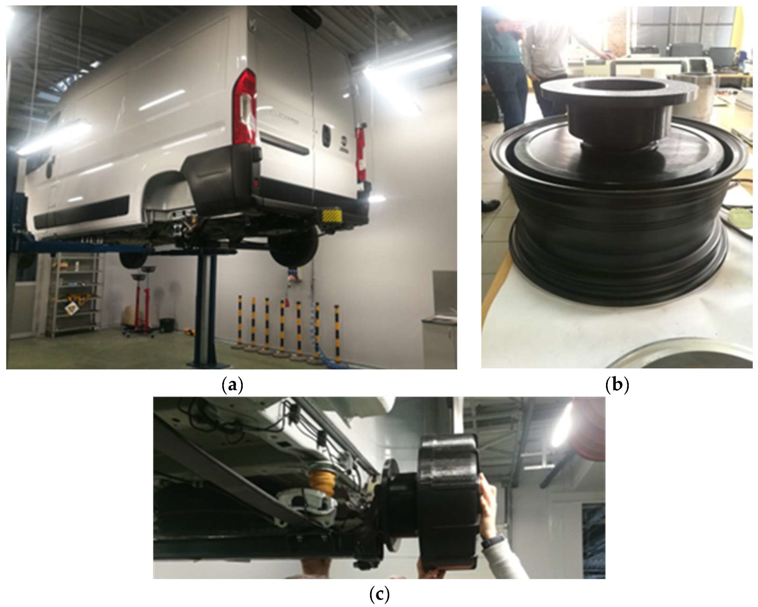
The article presents an important aspect of motor and drive design, concerning the simulation of motor operation in various car cycles, taking into account the control strategy and the selection of the supply voltage. It is important to properly select the vehicle driving cycles that reflect the actual dynamics of the car in various driving scenarios, not used to analyze the cycle for testing the emissions of internal combustion cars. Traction motors for installation in wheels of vehicles must have a relatively high torque at lower rotational speeds and a sufficiently high torque necessary to overcome resistance to motion at maximum speed and to maintain appropriate driving dynamics in the entire speed range. In the case of wheel hubs motors, an extremely important aspect is the operating temperature of sensitive elements such as windings or permanent magnets. These are compact motors, due to the very limited space in which they must fit, therefore their efficiency in terms of the required power, especially torque, must be increased in relation to standard motors. Due to their shape and the requirements for operating parameters, they are multi-pole motors, which are associated with higher frequency and higher losses in the magnetic core, permanent magnets, and AC losses in the winding. Available publications lack simulations of the wheel hub motors’ operation, which was designed for real dimensions, resulting from the available space and real mechanical requirements imposed by mechanical designers. The works carried out by the research team have been conducted for several years. Some of the results were presented in publications [27,28]. The concept of the motor under consideration is based on the analyzes and results of the work carried out earlier, including laboratory tests of prototype motors, calibration of computational models, and experience gained in designing in terms of mechanical aspects. There is a lack of traction calculations related to thermal calculations, which are key aspects of designing such demanding and specific motors. Figure 1 shows the Fiat Ducato with fittings of the 3D-printed model of the motor to the rim and the drive axle.
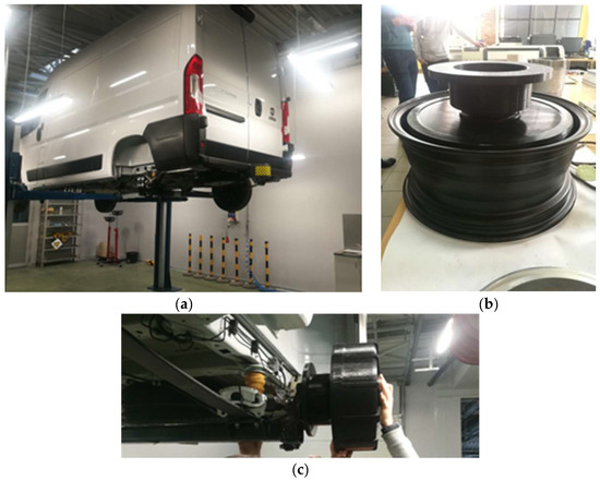
Figure 1.
Fitting 3D printed model of motor: (a) Fiat Ducato car; (b) in the rim; (c) at the drive axle.
The authors presented an aspect of wheel hub motor design including a thermal analysis of key motor components under conditions that reflect the predicted actual operating conditions. The selection of the appropriate driving cycles allows the assessment of the motor’s performance in driving conditions and the assessment of the influence of the selected supply voltage and control strategy. Such complete analyzes are lacking in scientific publications. The presented research results are also important due to the fact that the considered drive is hybrid. The analysis allows us to assess the extent to which the drive will be able to work only with electric motors, and in which operating ranges it will be necessary to cooperate with the internal combustion engine. Carrying out such tests at the stage of developing motors, drive components and power supply system is necessary, in particular, due to the fact that the weight and volume of the machine are limited. In this case, the most advantageous is the use of permanent magnet motors, the price of which, due to the cost of permanent magnets, may be higher than DC, induction, or reluctance motors, but they are characterized by a higher torque density to the total mass.
The use of permanent magnets requires such an analysis, because magnets are also an element whose permissible operating temperature may limit the operating range of the motor. The operating temperature of the magnets depends not only on the temperature of the winding and magnetic core, but also on the power losses that are generated in them, and these in turn depend not only on the design of the electromagnetic circuit but also on the operating point of the motor (current intensity, operating frequency of the electromagnetic circuit) and control strategy. Due to the application, the traction motor is characterized by a very wide range of changes in operating parameters, which exposes the motor structure to thermal tests in various ways. The authors performed an analysis that may be part of the methodology for designing motors of this type.
2. Calculation Model of the Motor
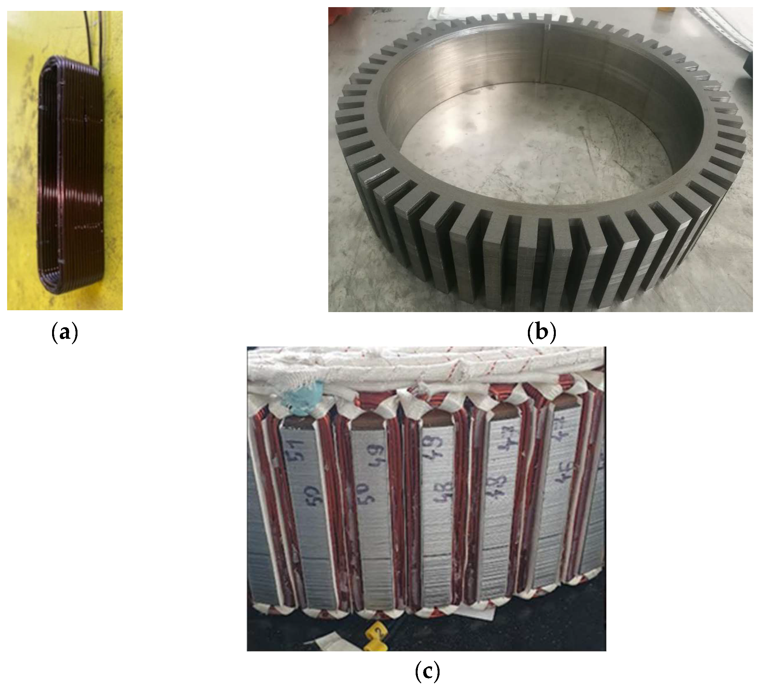
The motor under development is a synchronous motor with permanent magnets. The motor is an outer rotor with a surface permanent magnet (SPM) structure. The motor is liquid-cooled. The design assumes that the motor will fill the entire rim space. In this way, the full available space will be used to build and test the motor. In the future, it is assumed that if the driving parameters are achieved, work will be carried out to reduce the length of the machine. The motor winding is a double-layer winding with machine-wound concentrated coils. In this way, the overhang of the end windings (in relation to the distributed winding) can be significantly reduced, which allows for the reduction of the power losses generated in the winding and the reduction of the mass of the motor’s electromagnetic circuit. The stator slots are open. The winding is potted in a special epoxy resin, which improves heat dissipation from the stator winding. Figure 2 shows the coil, magnetic core and wound stator, built in the Łukasiewicz Research Network-KOMEL Institute. The magnets are axially segmented, each consisting of five segments along the length of the magnetic core in order to reduce the power losses generated in the magnets [29,30,31,32,33,34]. The power losses generated in permanent magnets decrease the efficiency of the motor and increase their operating temperature, which causes deterioration of their parameters, and in extreme cases may even lead to their demagnetization, especially in the second motor control zone (flux weakening) [35,36,37,38] are influenced by an external magnetic field.
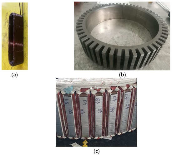
Figure 2.
Physical model of: (a) winding coil; (b) magnetic core; (c) stator.
The drive consists of two motors installed in the rear driving axle of the car. Each of the motors will be powered by a separate inverter. The assumed battery supply voltage is UDC = 400 V.
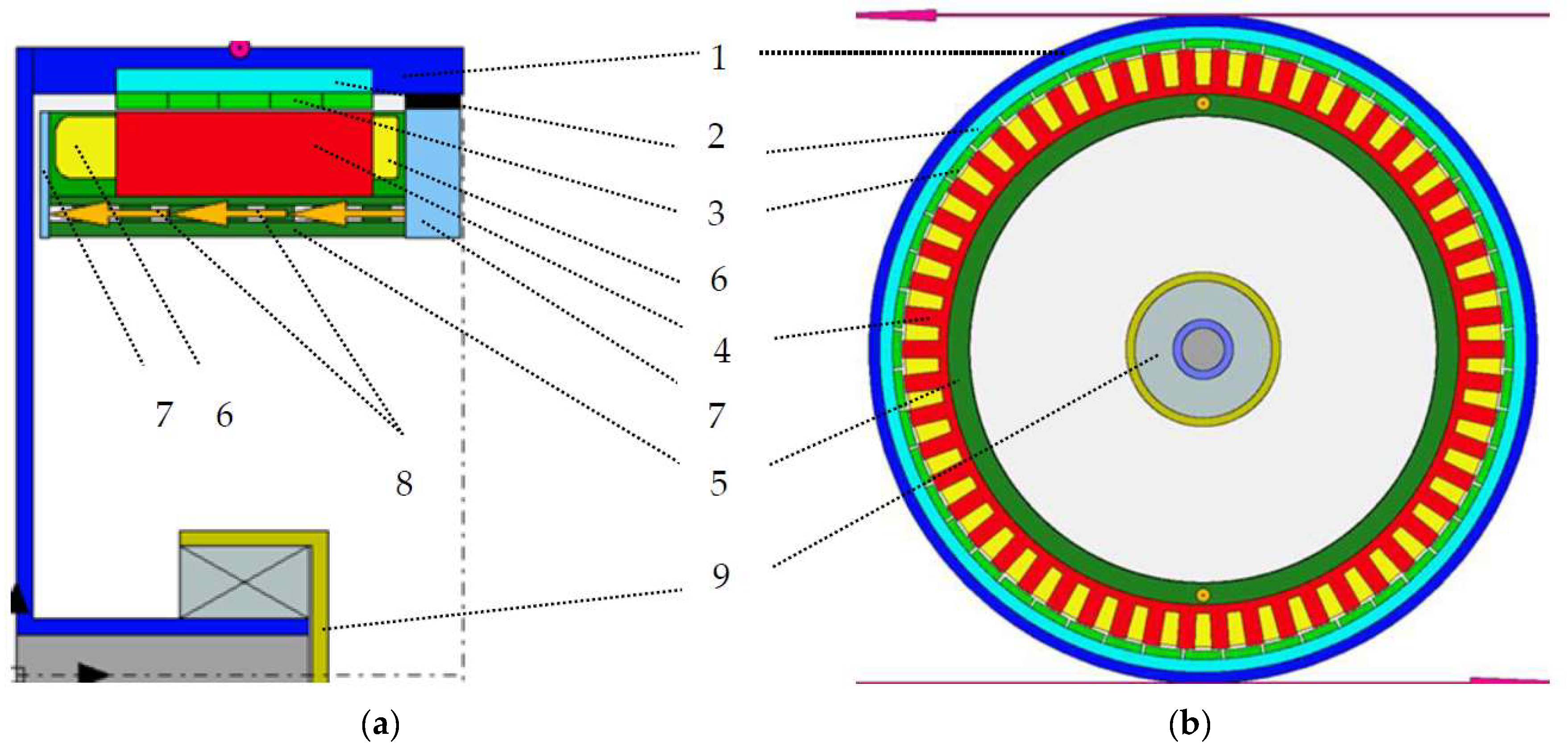
The motor was designed in the Ansys Motor-CAD (Figure 3). The dimensions of the electromagnetic and thermal circuit, such as inner and outer stator diameter, machine length, end-windings, dimensions of side heat sinks, and elements of the supporting structure and rotor diameter, result from the mechanical structure of the motor, structural elements and their strength, built-in resolver, cooling system, construction sealing, overall rims dimensions and elements of the brake system and suspension.
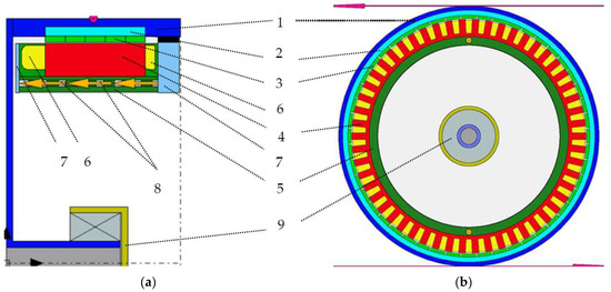
Figure 3.
Motor model in Ansys Motor-CAD software (a) longitudinal model (b) transverse model; 1-rotor, 2-rotor magnetic core, 3-permanent magnets, 4-stator magnetic core, 5-supporting structure, 6–end-winding, 7-side heat sink, 8-channels with flowing coolant, 9-bearing socket.
It is important that the simulations of the electromagnetic and thermal circuit take into account the permissible space limited by various mechanical aspects, because the wheel hub motors have a compact structure, the weight, dimensions, and parameters have to be optimized. Without carrying out design work on the mechanical structure of the motor, the permissible dimensions of the electromagnetic circuit cannot be determined.
Table 1 List of selected motor design and operating parameters.

Table 1.
Rated and design parameters of the motor.
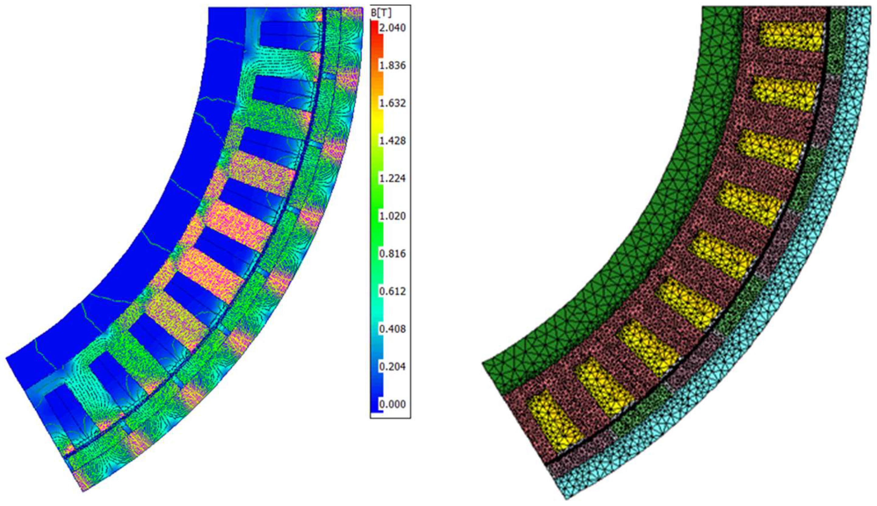
Figure 4 shows the FEM model of the motor with the calculated magnetic induction distribution in the magnetic core generated by permanent magnets.
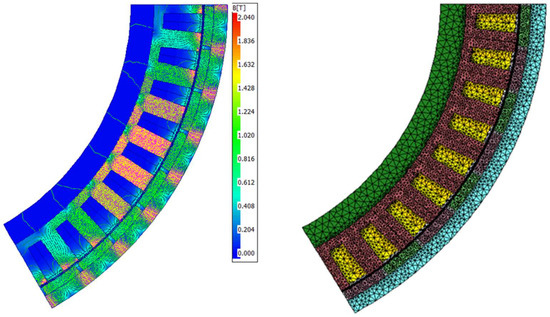
Figure 4.
Calculated magnetic induction distribution from the permanent magnets.
In a traction motor, especially in a compact design with limited dimensions, it is important to calculate the power losses, because their ratio changes depending on the operating point of the electric motor.
Bertotti method has been used for the calculation of magnetic core power losses in the elaborated models [39,40,41,42]. This lets us account for hysteresis, eddy current, and excess losses:
where: kh—hysteresis factor, Bm—flux density, f—frequency, σ—conductivity, b—thickness of single electrical sheet, ke—excess loss coefficient.
First part of the formula relates to hysteresis losses (due to the hysteresis loop of ferromagnetic material of the magnetic core). The second part of the formula covers eddy current losses (eddy currents are induced in the magnetic core). The third part relates to excess losses, caused by interaction of the external magnetic field and local magnetic fields generated by eddy currents.
In analysis, copper losses are split into constant losses and losses due to skin effect, i.e., AC winding (AC copper) losses. Copper losses are calculated on the basis of a well-known relationship:
where: I—RMS-value of supply current, R(υ)—winding resistance as a function of temperature
AC Losses on AC windings can be determined by two methods, full FEA and hybrid FEM. The full FEM method uses an accurate model where the induced eddy currents and then losses are calculated separately for each conductor. Obviously, this is the most time-consuming method. Hybrid FEM uses the flux density levels calculated by FEM for each slot, and then the losses are calculated analytically. This method is quick, but much less accurate at relatively high frequencies and relatively large conductor cross-sections. In our case, the mixed method was adopted. For the operating point with maximum speed and load, the losses were calculated using both methods, and then the correction factor was calculated according to the formula:
where AC winding losses are calculated by the Full FEA method, and AC winding losses are calculated by the Hybrid FEA method.
Since further analysis takes into account a wide load/speed range, AC winding losses are calculated with the Hybrid FEA method and each result is then multiplied by a correction factor.
The designed PMSM motor requires high torque at low rotational speeds and a wide range of rotational speeds with constant power in the area, where the DC bus voltage is the limitation. Various control strategies are used to ensure favorable motor parameters. In the area of low rotational speeds, high torque is achieved by using the maximum torque per ampere (MTPA) control strategy. The MTPA control strategy is used for minimizing winding losses. The area of a wide range of rotational speed while maintaining constant motor power is obtained using the flux weakening (FW) or maximum torque per volt (MTPV) control strategy [43,44,45,46,47,48].
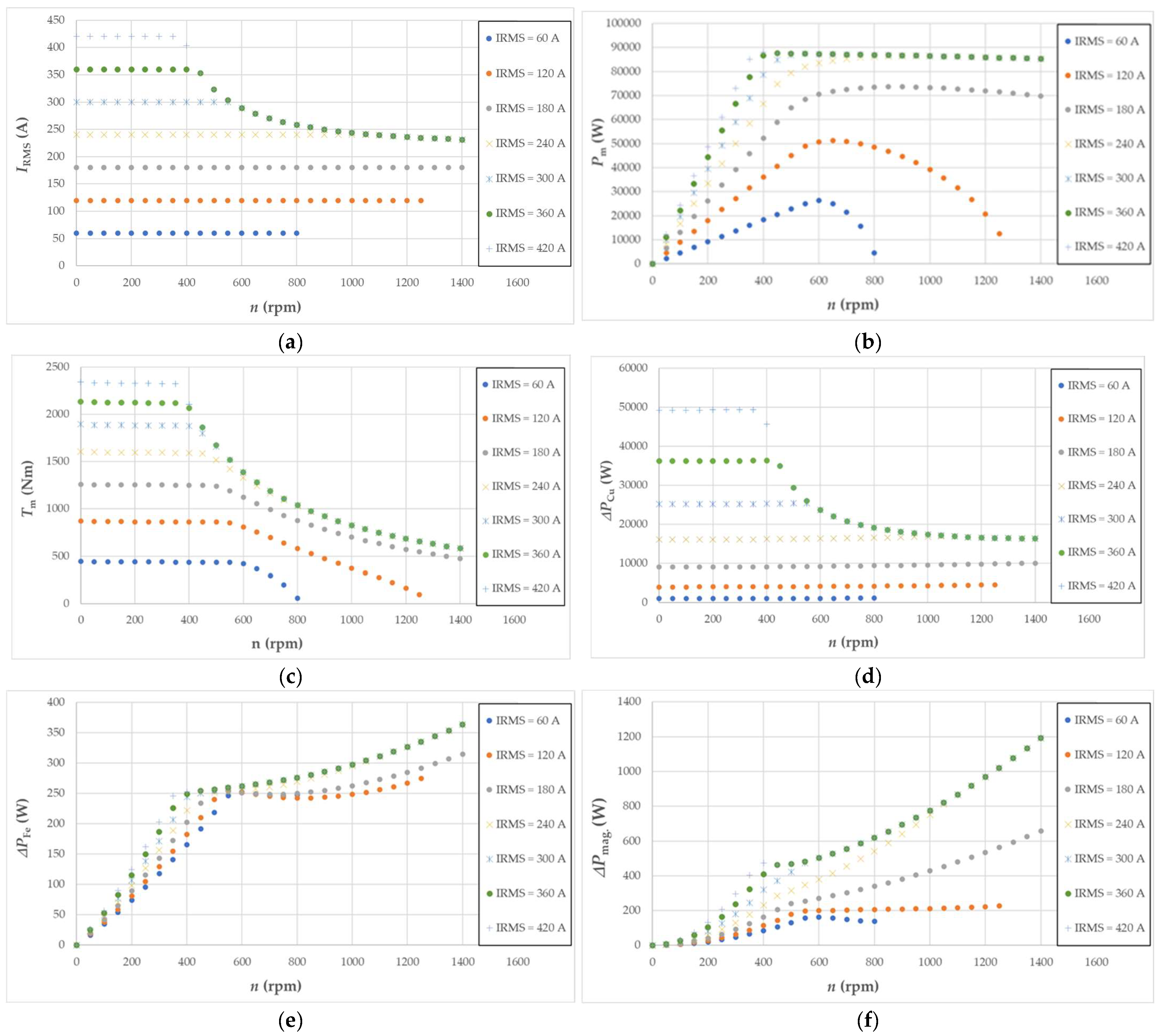
Figure 5 shows the calculated motor characteristics: torque (a), mechanical power (b), efficiency (c), power losses generated in the winding (d), in the magnetic core (e) and in permanent magnets (f) in rotational speed function for seven different currents.
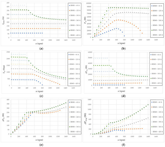
Figure 5.
Calculated motor characteristics as a function of rotational speed: (a) supply current; (b) mechanical power; (c) torque; (d) power losses in the winding; (e) power losses in the magnetic core; (f) power losses in a permanent magnet.
In Figure 5a,c, it can be seen that the maximum supply current corresponds to the maximum torque only in the zone without flux weakening (MTPA control). In the zone with flux weakening, increasing the rotational speed, while maintaining the voltage limited by the DC bus, is accomplished by a space vector along the d-axis of the current, which generates a flux in the opposite direction to the flux produced by permanent magnets. In the MTPV control, the possible maximum torque is obtained at a current lower than the maximum current, which has a positive effect on the efficiency of the motor and reduces winding (Figure 5d). For currents, IRMS = 240 A, IRMS = 300 A, IRMS = 360 A and IRMS = 420 at higher rotational speed the torque and losses in the machine have the same value, because all currents are within the limits of voltage elipse and current circle defined for MTPV control (Figure 5c–f) [44]. At higher rotational speeds, the torque drops much more smoothly than in the FW control (Figure 5c). For the values of the supply currents IRMS = 60 A, IRMS = 120 A and IRMS = 180A (Figure 5c) there is an FW control, where at a constant value of the RMS current, the share of the space vector of the current in the d axis of the motor increases, which results in an increasing weakening of the flux from permanent magnets and decreases losses in the machine. This results in an almost linear decrease of the torque, the decrease of the torque in such control, at higher rotational speeds, is much more visible than in the MTPV control. With insufficiently high RMS current values (60 A and 120 A supply current), it is impossible to achieve the maximum rotational speed and at the same time generate the appropriate torque, due to the too- high value of the current component in the d-axis in relation to the current component in the q axis of the motor.
3. Thermal Calculations
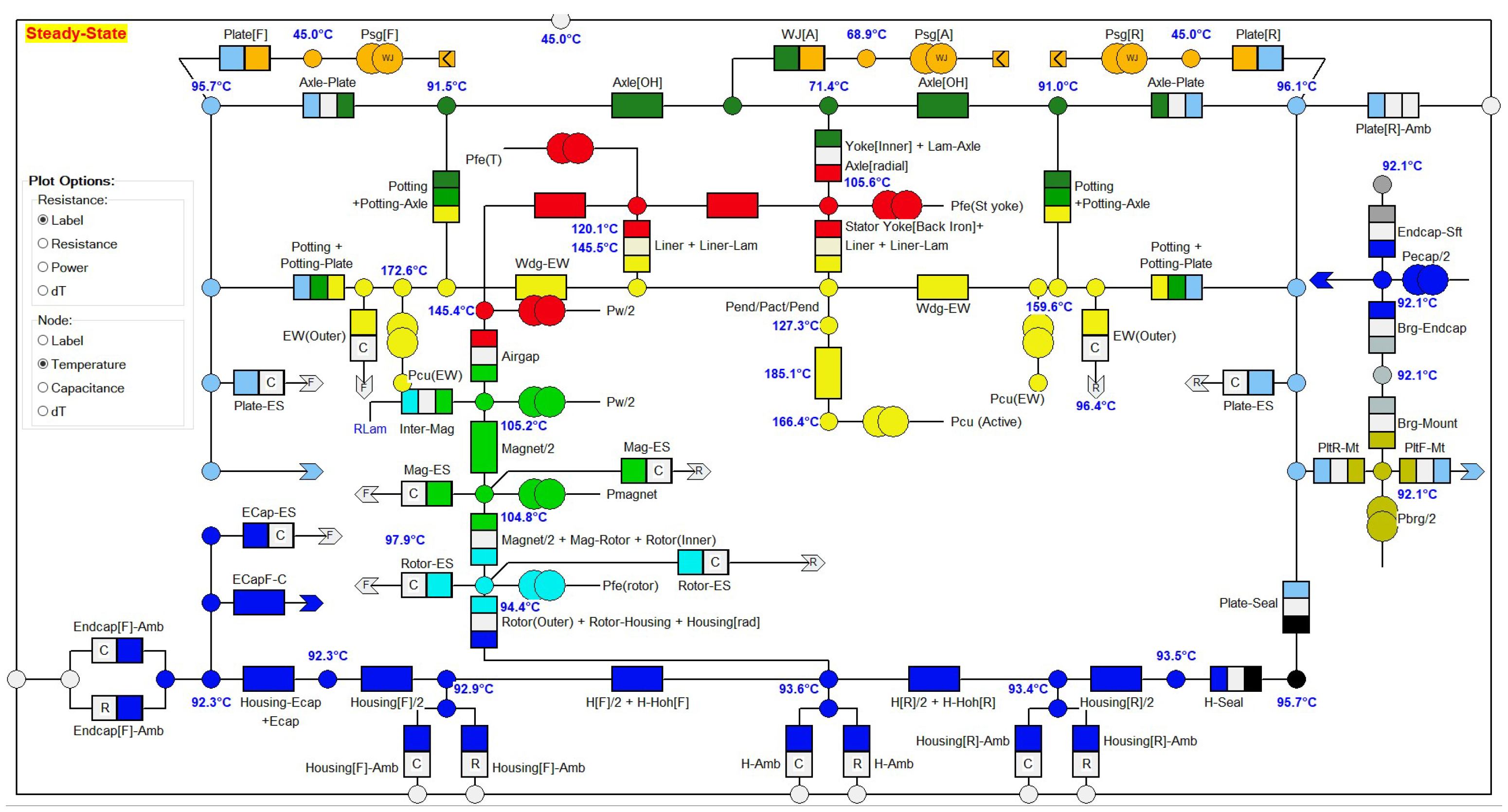
In the Ansys Motor-CAD program, a thermal motor model has been developed. Figure 6 shows a simplified equivalent thermal diagram of the motor. The thermal schema method is commonly known and commonly used in calculating electrical machines [49,50,51]. The program also enables the analysis of slot cross-sections on simplified FEM models in order to calibrate the network of the model.
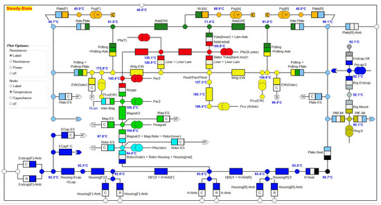
Figure 6.
Simplified equivalent thermal diagram of the motor in the ANSYS Motor-CAD program.
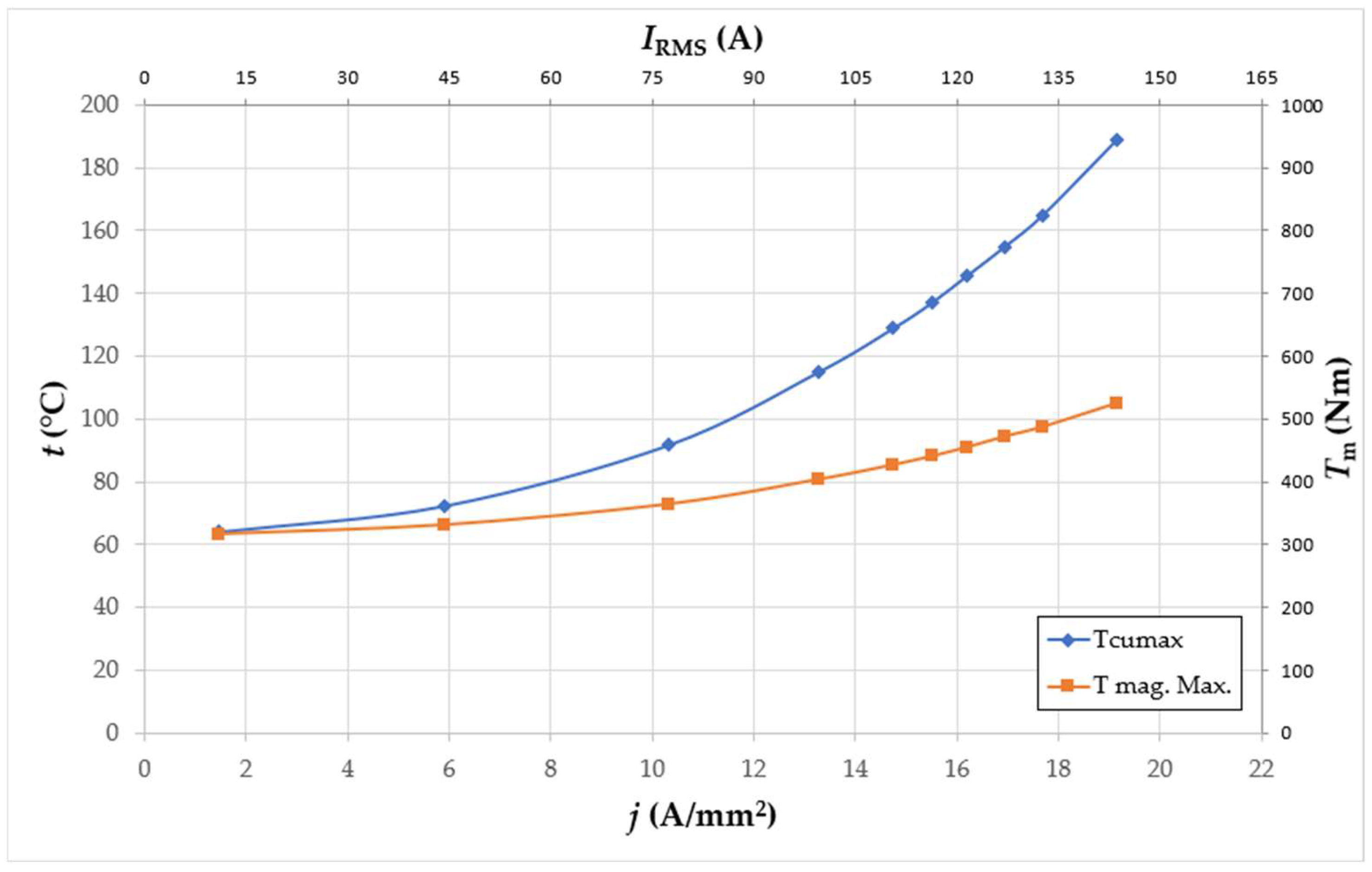
Figure 7 shows the temperature characteristics of winding (hotspot) and magnet, calculated in the ANSYS Motr-CAD program as a function of the supply current. The calculated points of the torque correspond to the points on the calculated temperature characteristic. The calculated characteristics show that when supplied with IRMS = 130 A (current density j = 19.2 A/mm2) and the assumed operation S1, the motor produces a torque equal to Tm = 902 N m. At this operating point, the maximum temperature in the winding is set at TCu = 189 °C, while the temperature of permanent magnets is set at Tmag. = 105 °C.
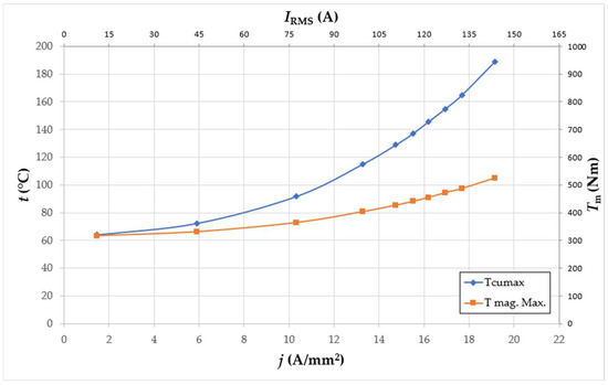
Figure 7.
Calculated temperature characteristics of winding (hotspot) and magnet, calculated in the ANSYS Motr-CAD.
As the intensity and density of the current decrease, the temperature of the magnets and the winding approaches the set coolant temperature equal to Tcool. = 60 °C. Using the insulation class allowing the winding temperature TCu = 200 °C, it can be assumed that the motor at this rotational speed works with a current density of j = 19.2 A/mm2, while maintaining temperature safety with a margin of about 10 °C.
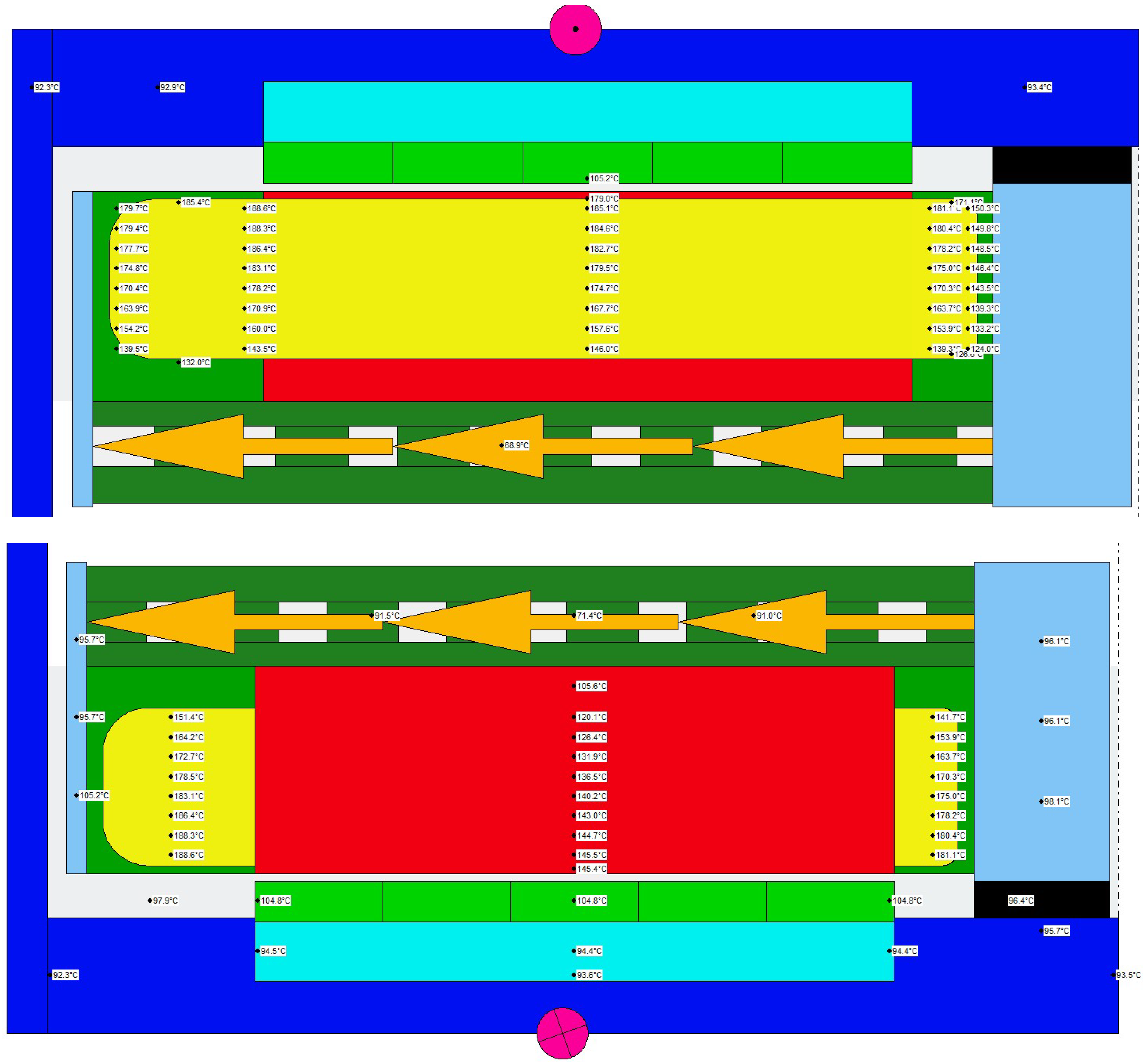
For this operating point, the calculated temperature distribution in individual motor components has been presented (Figure 8).
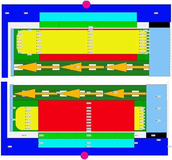
Figure 8.
Calculation results of the motor temperature distribution for the operating point Tm = 902 Nm and n = 400 rpm.
The model (Figure 8) shows the calculated temperature distribution for operating point Tm = 902 Nm and n = 400 rpm.
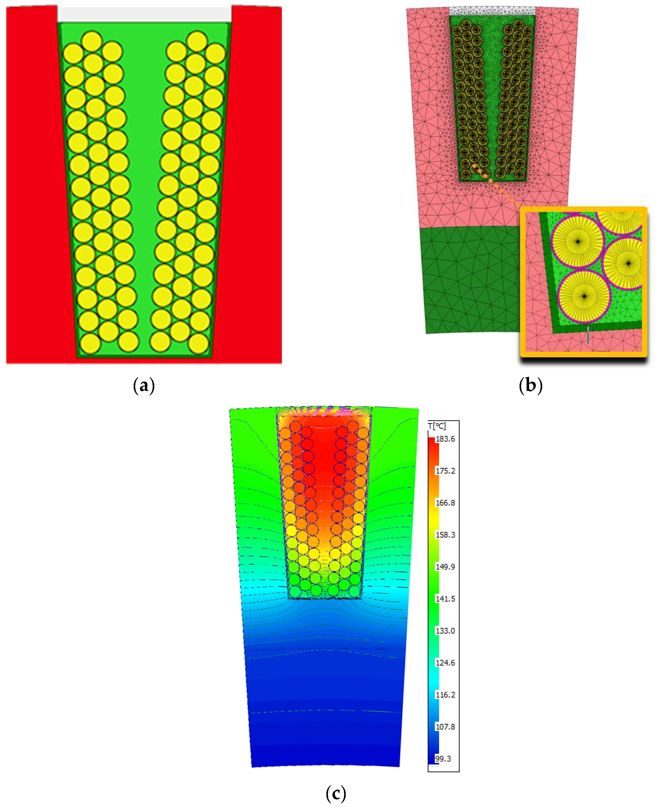
Machine winding of the coils allows for a large filling of the slot (and a very good adjustment of the winding wire distribution in the coil). During manual winding, especially in the case where the motor is wound with a bundle of parallel wires, obtaining a large slot filling is limited, because the wires in the slot are arranged randomly, twist, and cross. It also has a negative impact on the thermal performance of the motor, because the interlacing causes the free space in the slot between the coil and the stator magnetic core, which is the path of heat dissipation from the winding to the cooling system, to be filled with air, impregnation and/or epoxy resin in places. These are spaces where thermal conductivity is much lower than copper conductivity. Figure 9 shows a cross-section of the slot model with the location of the wires in the single coil and the calculated temperature distribution in the slot for the operating point Tm = 902 Nm and speed n = 400 rpm. From the calculated temperature distribution of the winding in the slot, the maximum temperature is TCu max. = 183.1 °C, mean temperature TCu av. = 167.3 °C, while the minimum temperature TCu min. = 133.1 °C. The calculated temperatures on the schematic model (Figure 8) are analogically TCu max. = 185.4 °C, TCu av. = 165.8 °C, TCu min. = 127.4 °C. The results of calculations using both methods are similar with satisfactory accuracy.
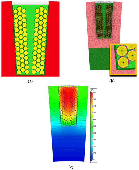
Figure 9.
Longitudinal section of the circuit model of the motor with the housing: (a) through the stator slot; (b) FEM model; (c) simulation result (Tm = 902 Nm, n = 400 rpm).
4. Driving Cycle Simulation-Model
The Lab module of the Ansys Motor-CAD program was used to carry out the thermal analysis while driving the car, which allows for making simulations of coupled models of the electromagnetic circuit and the thermal model. During the simulation, it is possible to set the required driving cycle of the car and use a number of parameters to build a model of the vehicle. The program calculates the torque demand for the vehicle model on the basis of the vehicle speed requirements in the driving cycle. Calculations can be made taking into account the coupling with the thermal model. Such calculations take into account the influence of temperature on the operating parameters of the electromagnetic circuit.
The vehicle model is based on the analysis of the forces acting on the vehicle while driving at constant speed: rolling resistance, aerodynamic resistance, climbing force, and during acceleration and braking.
The formulas used in the model are presented below.
where: FR is rolling resistance, kr is the rolling resistance coefficient, m is the mass of the vehicle, and g acceleration due to gravity;
where: FD is aerodynamic resistance, ρ is the air density, v is the velocity of the vehicle, v0 the headwind velocity, Cd the vehicle drag coefficient, and Af the vehicle’s affective frontal area.
FC is climbing force, calculated from the formula:
where: θ is the gradient of the slope.
FT is the total force required for constant vehicle motion:
Fa is acceleration, calculated from the formula:
where: δ is the mass correction factor.
The torque is calculated from the formula:
where: rω is the wheel radius and nd the final drive ratio.
The driving cycles are described as a set of points on the vehicle speed versus time characteristics. They are determined by tests carried out on real vehicles. The driving cycles are mainly used to assess the fuel consumption and emissions of a vehicle according to the standards for different types of vehicles with different drives. The driving cycle is mapped to a chassis dynamometer where tailpipe emissions are collected and analyzed to evaluate the emission factors.
Another test is the motor dynamometer test, where the evaluation is made on the basis of a set of torque and speed points.
The difference between modal and transient cycles is that modal cycles are a compilation of acceleration and constant velocity periods. They cannot represent the actual behavior of the driver. Transition cycles, on the other hand, include many speed changes typical of driving conditions on roads with average driving dynamics. Such cycles can be considered in the motor thermal calculations because they represent the average driver’s ride.
Artemis cycles were used to perform a thermal analysis of the motor [52,53]. The cycle reflects driving a car around the city, taking into account the dynamics characteristic of an average driver.
Table 2 presents a summary of the main parameters of selected Artemis driving cycles: driving time, distance traveled, average speed, maximum speed, percentage of stoppage, vehicle speed up to v = 50 km/h, medium speed up to v = 90 km/h, high speed above v = 90 km/h The analysis shows that the range of vehicle speed up to v = 90 km/h is exceeded in the Artemis Road and Artemis Motorway cycle. In the Artemis Road cycle, the speed ranging from v = 90 km/h to v = 111.1 km/h represents a 2% share of the cycle. This is a speed range that is outside the intended speed range for a pure electric vehicle. On motorway cycles, the speed range above that required for electric drive is 70–71%.

Table 2.
Artemis driving cycle parameters.
In the Artemis Road cycle, the speed range to v = 90 km/h covers 93% of the entire driving cycle, while the Artemis Urban cycle does not exceed the speed above v = 57.3 km/h.
Table 3 presents the vehicle parameters adopted for the calculations.

Table 3.
Artemis driving cycle parameters.
The assumed vehicle weight is the maximum laden weight for the selected Fiat Ducato model. The frontal area and the wheel radius were determined by the characteristic dimensions of the car. Mass Correction Factor or rotational inertia factor that compensates for the increase in mass of the vehicle due to its rotating mass on board. The gear ratio is 1 because we are considering direct drive. The Motoring Torque Ratio is equal to 0.5 because we assume that each of the two motors produces half the torque needed.
Generating Torque Ratio is equal to 0.25 (in total, both motors have half the necessary braking torque in the cycle).
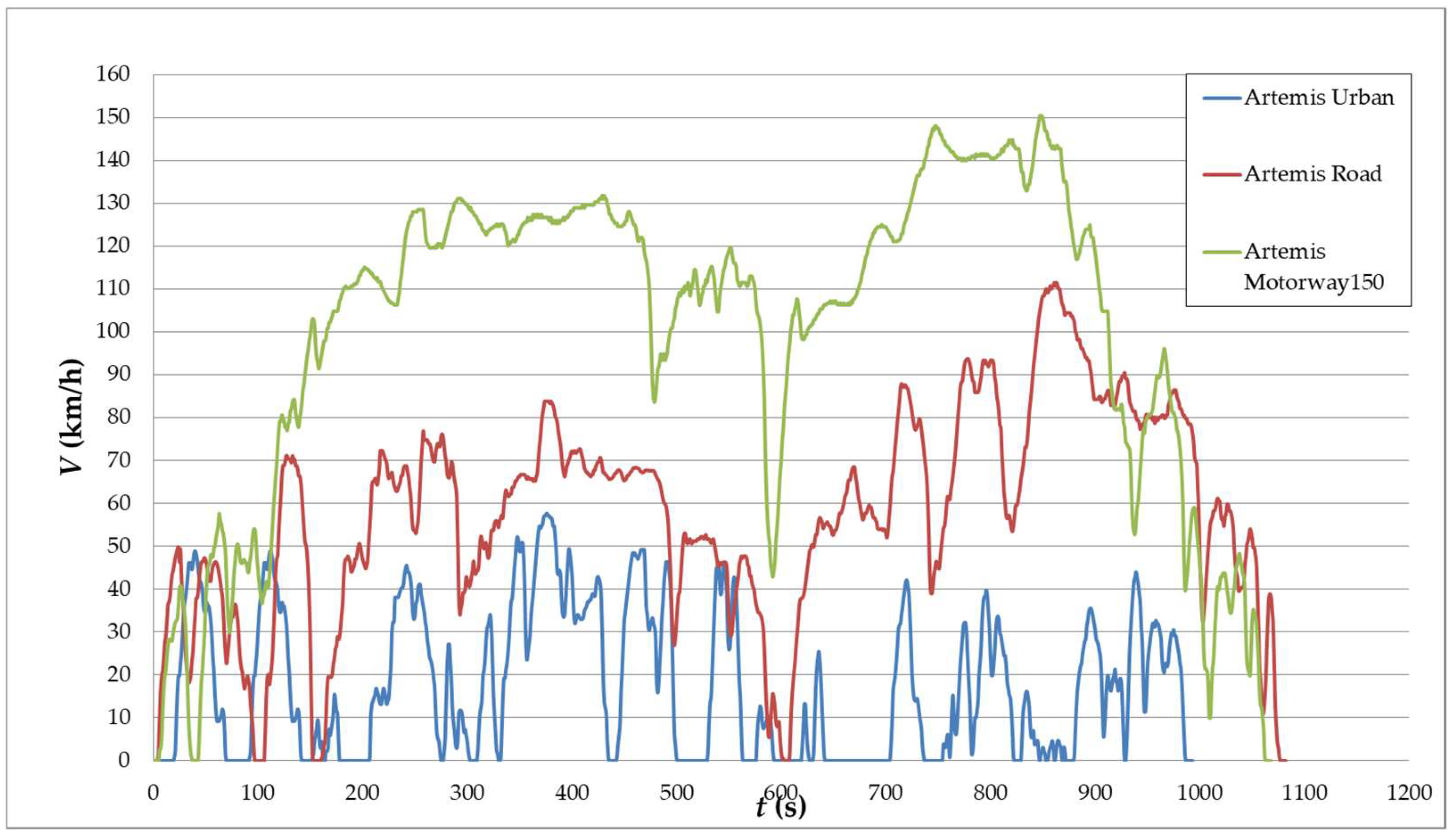
Figure 10 shows the vehicle speed for the three driving cycles considered in the further analysis: Artemis Urban, Artemis Motorway150, and Artemis Road.
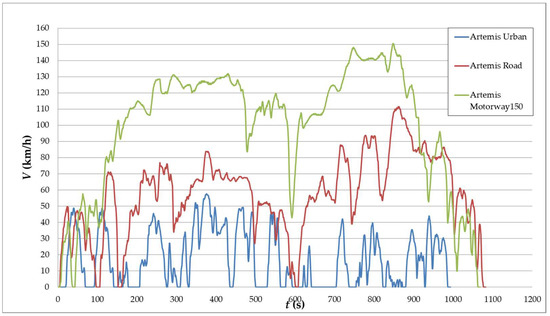
Figure 10.
Vehicle speed waveforms for Artemis driving cycles.
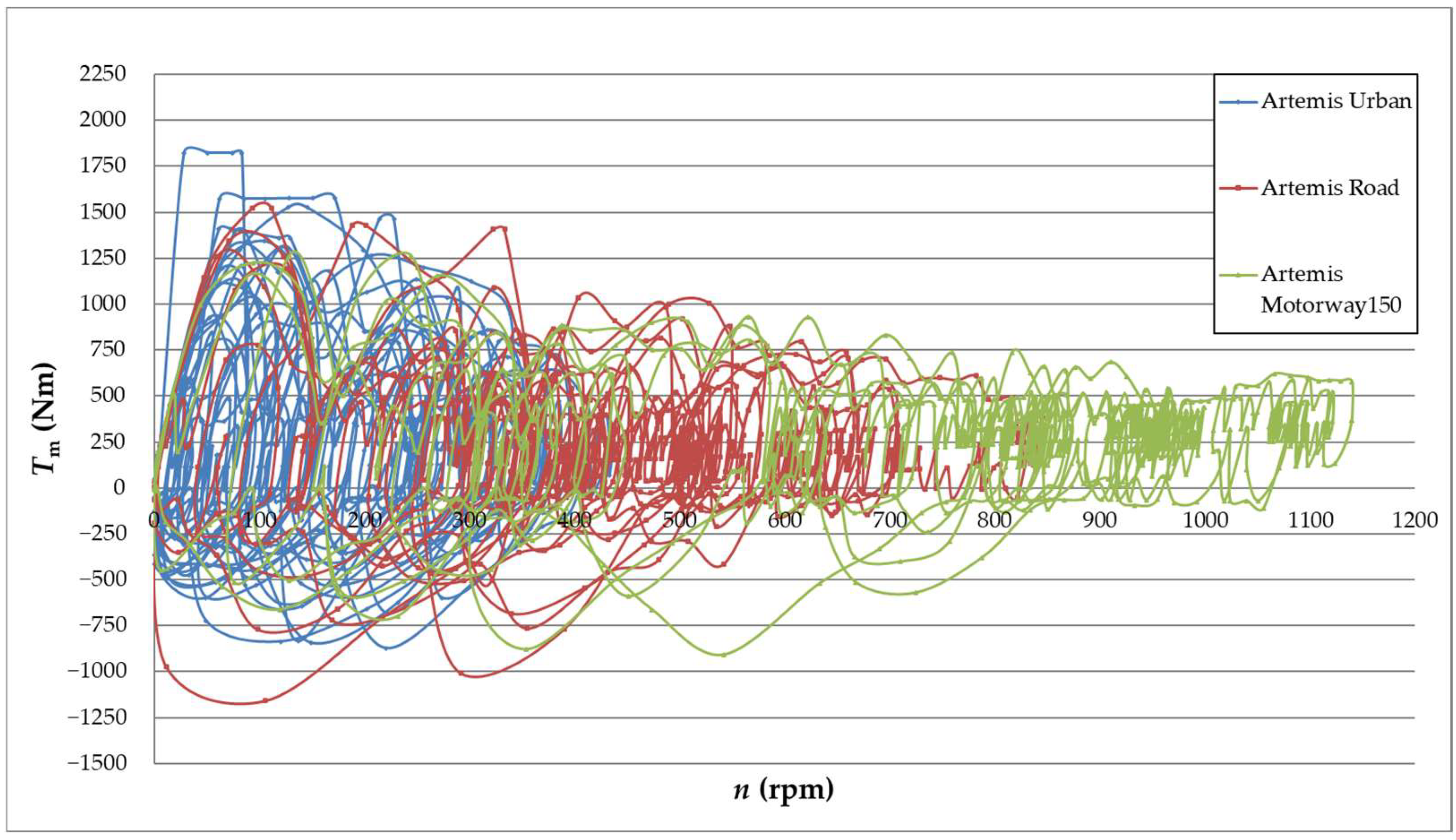
The torque curve for the considered driving cycles was determined by the simulation method. Figure 11 shows the required waveforms of torque as a function of motor rotational speed, resulting from the demand at different vehicle speeds during the driving cycle.
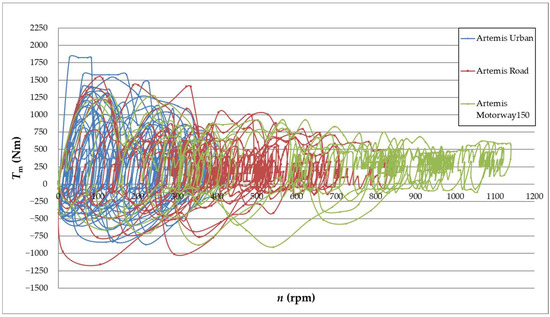
Figure 11.
Curves showing the mixing of the motor operating point defined by torque and rotational speed during the Artemis Urban, Artemis Road, and Artemis Motorway150 driving cycle.
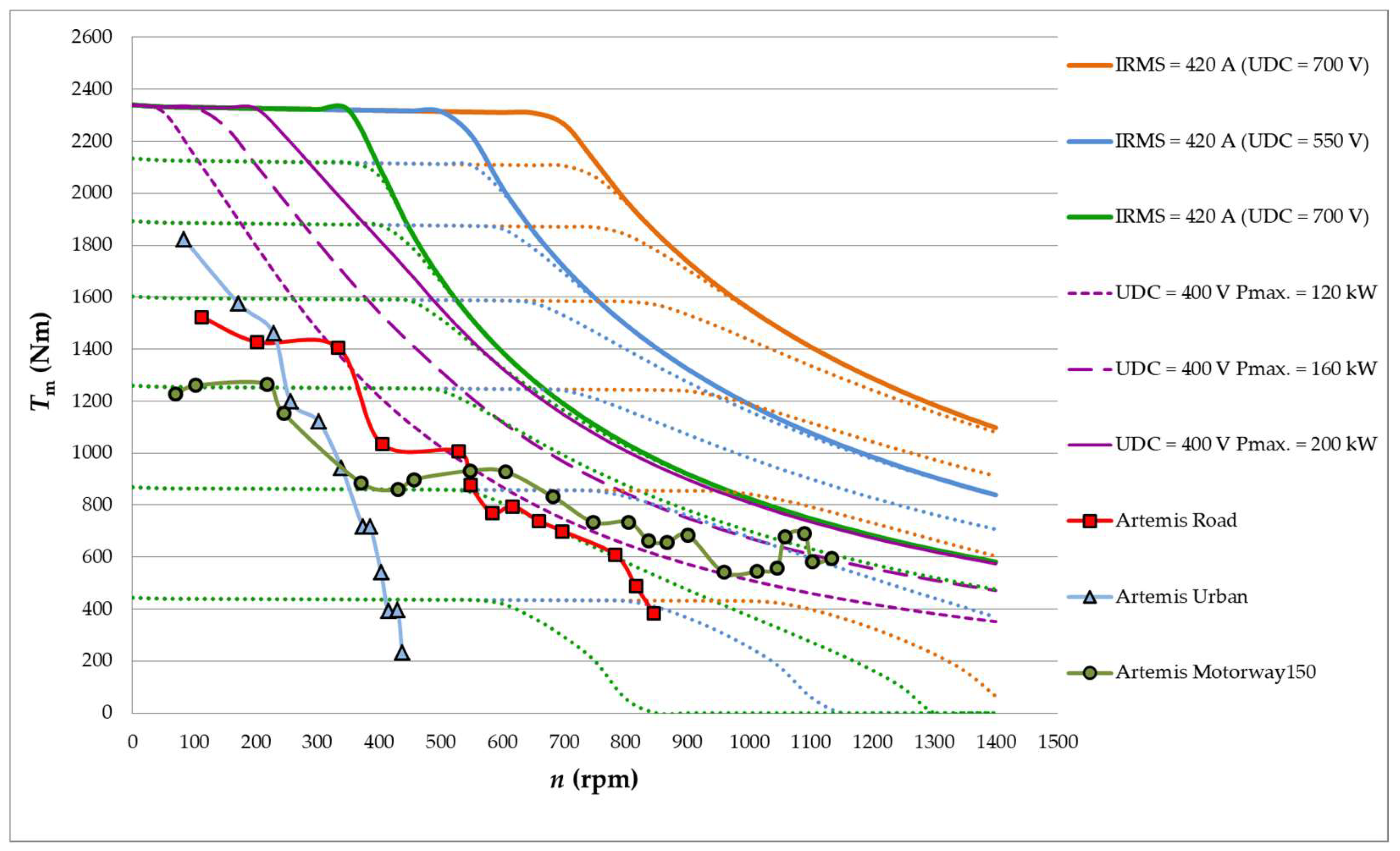
Then, the envelope of maximum torque as a function of rotational speed was determined (Figure 12). The maximum torques at various rotational speeds are the torques that the motor must generate to obtain the required acceleration in a given driving cycle
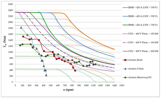
Figure 12.
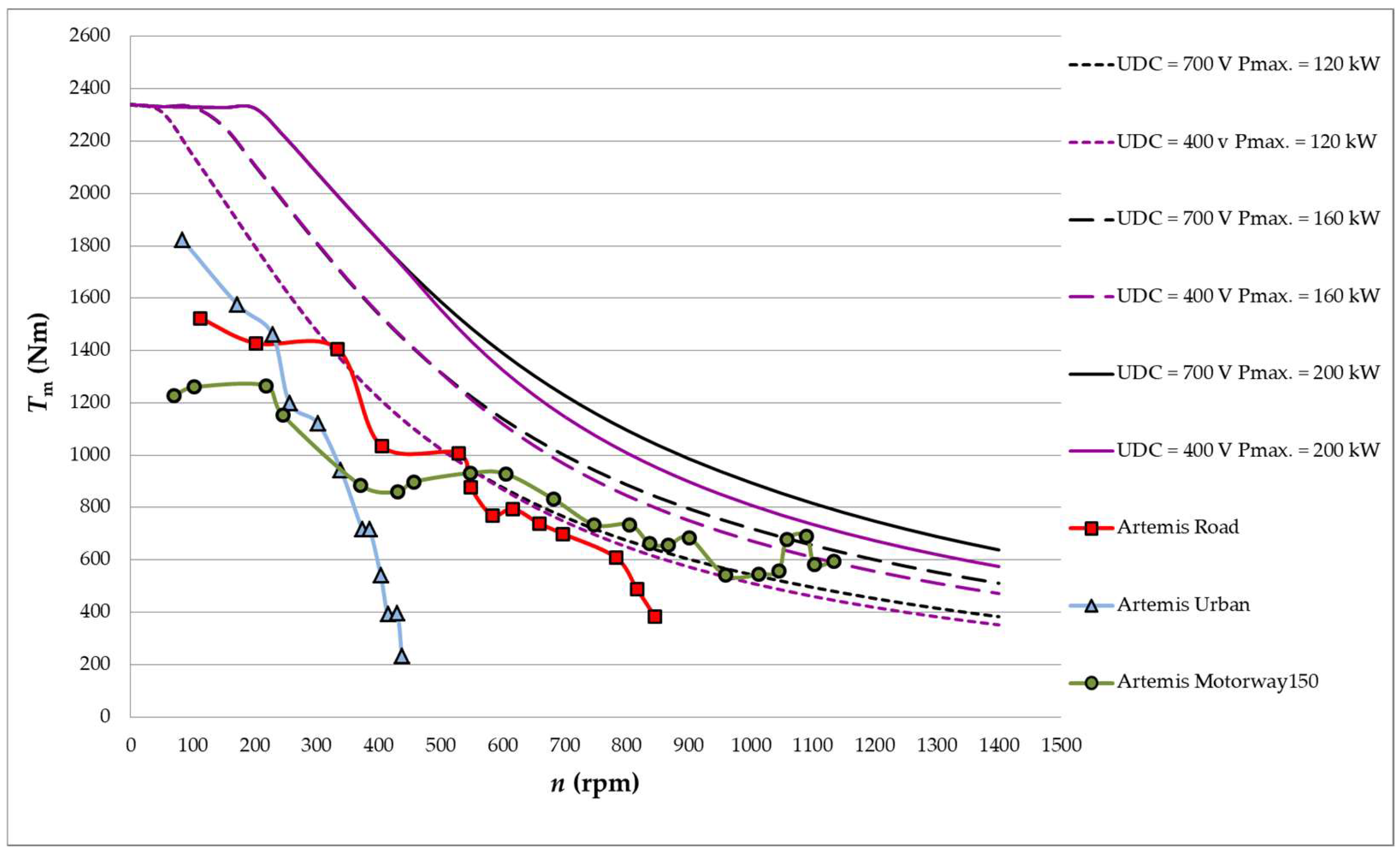
Calculated torque characteristics of the motor for three different supply voltages of the UDC drive with the three limits of the drive input power and the maximum torque characteristics for the given rotational speed of the Artemis Urban cycle, Artemis Road and Artemis Motorway150.
Figure 12 provides the basis for the further analysis of motor performance conducted in this article. The figure shows the family of motor characteristics, calculated for the battery voltage UN = 400 V (green color), analogous to the characteristics shown in Figure 5. The characteristics are marked with points representing the highest torque of individual driving cycles. The highest torque of approx. Tm = 1800 Nm is required for the Artemis Urban cycle at low speeds of up to approx. n = 100 rpm. The entire urban cycle is confined to the first torque control zone.
The Artemis Road driving cycle is characterized by a lower required maximum torque of approx. Tm = 1500 Nm at a rotational speed of up to approx. n = 100 rpm. At the highest motor speeds/vehicle speeds, the motor runs in the flux weakening zone.
In the Artemis Motorway150 cycle, compared to the rest of the cycles, the maximum torque required is lowest in the first control zone, while it is highest in the second control zone, and covers the range of the highest rotational speed.
Figure 12 also shows the analogous torque characteristics of the motor for higher supply voltages UDC = 550 V (blue) and UDC = 700 V (orange).
Increasing the supply voltage reduces the motor operating range in the flux-weakening region.
Additionally, in Figure 12 the lines limiting the operating range of the motor powered by the voltage UDC = 400 V, the available battery power have been presented in purple. The maximum battery power should be selected so as not to limit the required vehicle parameters. The choice of battery power should take into account all the car components it supplies. The graph takes the battery power minus the power needed to power the rest of the components besides the motor. Power limits were presented at the level of PIN = 120 kW, PIN = 160 kW, PIN = 200 kW. It is the power to power up both motors, i.e., if the battery is limited to PIN = 120 kW, a single motor is limited by the power supply to 60 kW.
From the waveforms presented in Figure 12, it can be concluded that for the limitation of the supply power to PIN = 120 kW, the urban driving cycle can be achieved, while for the on-road cycle, the power supply is insufficient at two points, which means that the assumed driving dynamics is not maintained. For such a power limitation, the Highway cycle is even less feasible. Similarly, increasing the allowable power supply of motors to PIN = 160 kW will enable the achievement of the required torques for the road cycle, and increasing the power to PIN = 200 kW will also cover the motorway cycle, although with a small reserve of power at the highest rotational speeds.
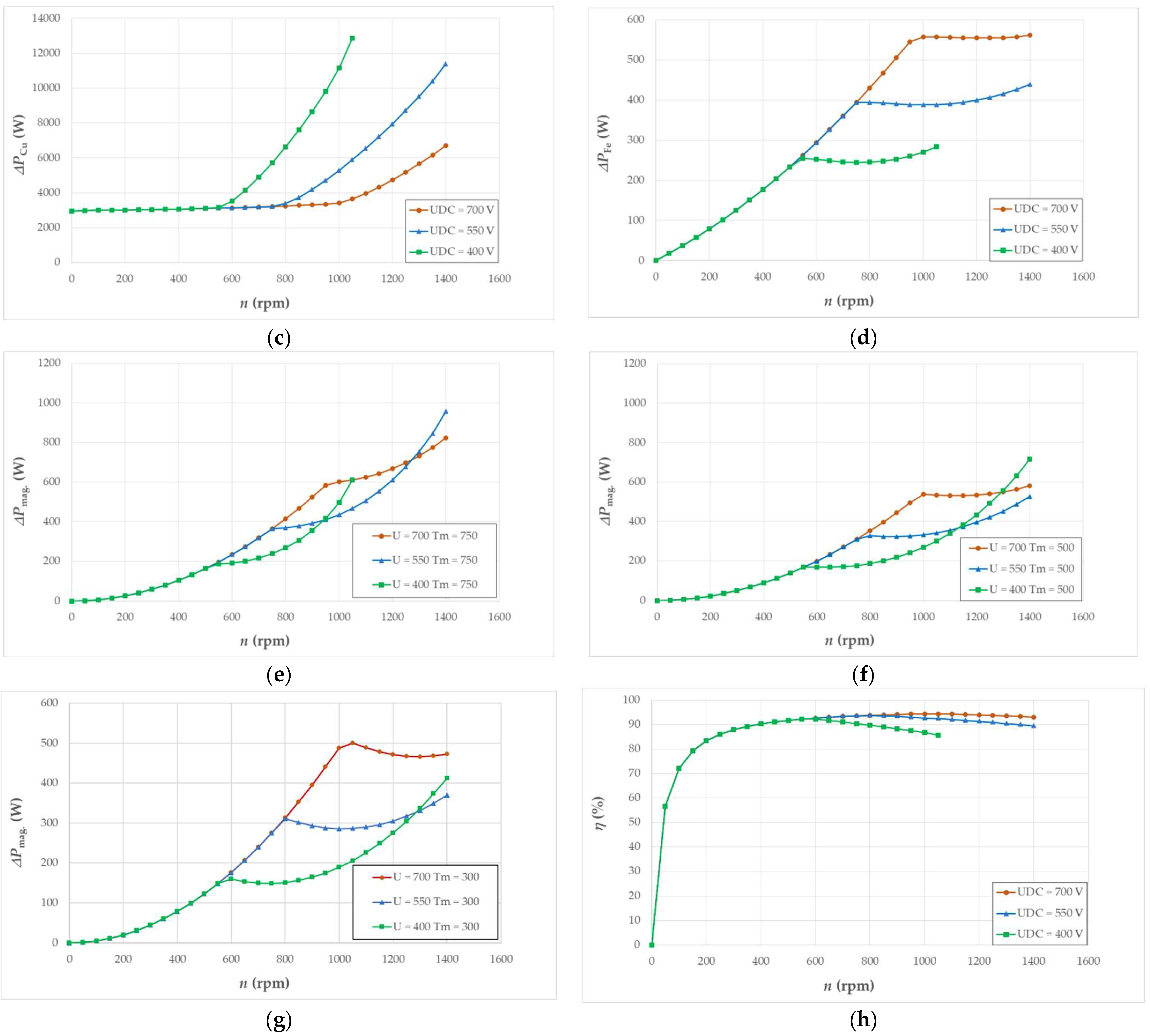
The following graphs, shown in Figure 13 the calculation results for the three voltages under consideration. The calculated characteristics relate to the calculations for a constant torque Tm = 750 Nm in the speed range from n = 0 rpm to n = 1400 rpm.

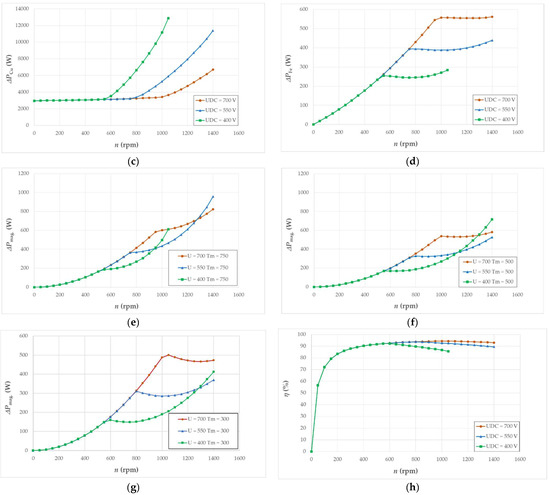
Figure 13.
Calculated characteristics of motor operating parameters for three drive supply voltages as a function of rotational speed and torque Tm = 750 Nm: (a) torque; (b) supply current; (c) power losses in the winding; (d) losses in the stator magnetic core; (e) power losses in magnets; (f) power losses in magnets for Tm = 550 Nm; (g) power losses in magnets for Tm = 300 Nm; (h) motor efficiency.
Figure 13a shows the torque characteristics as a function of rotational speed, calculated for the constant temperature of the winding and permanent magnets. For the voltage UDC = 400 V, the torque Tm = 750 Nm cannot be achieved in the full range of rotational speeds (the torque is achieved up to a speed of n = 1050 rpm). For the voltage UDC = 550 V and UDC = 700 V, the considered torque is achieved in the entire rotational speed range, up to n = 1400 rpm. Figure 13b shows the IRMS current waveform for various UDC supply voltages. The figure shows at what rotational speed, depending on the supply voltage, it is necessary to flux weakening the motor to be able to work with the torque Tm = 750 Nm (the current value increases). Similarly, the power losses in the winding increase in Figure 13c. Figure 13d shows the calculated power losses in the stator magnetic core. While the losses in the winding increase with the increase of the supply current, the losses in the magnetic core decrease. This is due to the flux weakening process, which lowers the value of the magnetic induction in the magnetic core, thus lowering the value of power losses. Figure 13e–g shows the power losses in permanent magnets. As in the case of the losses in the stator magnetic core, also in magnets, flux weakening lowers the losses in the magnets, while the effect is limited and decreases with increasing flux weakening and current intensity, which is visible when comparing the loss waveorms for two different to request. Figure 13f,g show that for a torque smaller than Tm = 550 Nm and Tm′ = 300 Nm, the rotational speed range in which the power losses generated in the magnets are lower when powered by a lower voltage (UDC = 400 V) is wider. It can be concluded that the use of a higher supply voltage will significantly reduce the power losses in the motor winding during operation in the flux weakening region, it will also reduce the power losses in the magnetic core of the motor (also only in the flux weakening region), while in the case of losses in permanent magnets, a reduction in these losses can also be expected. It should be noted that the analysis concerns the calculation of the cases of all three voltages for the same operating temperatures (TCu = 113 °C and Tmag. = 84 °C). The losses generated in the magnets depend on the excitation, which in turn depends on the operating temperature of the magnets, which is influenced by the temperature of other elements, mainly the winding and the magnetic core.
Figure 13h shows the calculated performance characteristics for the same conditions as the graphs discussed. The characteristics show a large impact on the efficiency of the motor of limited voltage and the associated earlier rise of the IRMS current, which is the necessity to start flux weakening at a lower rotational speed, which results in a faster increase of losses in the winding. The ratio of the winding losses to the losses generated in the magnetic core and in the permanent magnets shows that these losses determine the efficiency of the machine.
Figure 14 shows the maximum torque and power limitations, but for two different voltages, for UDC = 400 V and 700 V as in Figure 12 The comparison of the operating range of the motor with different voltages is justified due to the differences in efficiency depending on the supply voltage. The comparison of the characteristics shows that with a higher supply voltage and the same power limitation, the possible range of motor operation is higher, which results in the torque reserve increasing with the increase in the permissible motor supply power. This is clearly seen in the points of the required maximum torque at the high rpm of the Artemis Motorway150 drive cycle. With the supply power limited to PIN = 200 kW and the supply voltage UDC = 400 V, the maximum required torque at n = 1050 rpm is barely achieved. With a voltage increased to UDC = 700 V it is achieved with a torque reserve.
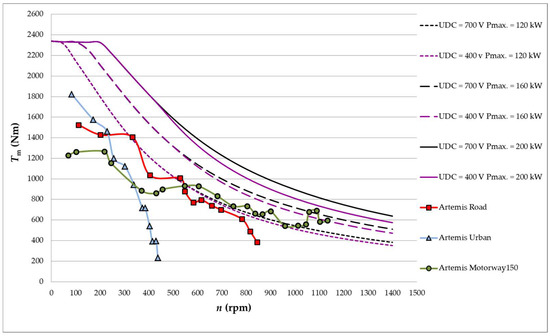
Figure 14.
Maximum torque waveforms for different motor speeds in Artemis Urban, Artemis Road, and Artemis Motorway150 Cycle and plotted torque characteristics with drive input power limits for two different drive supply voltages.
The test results show the dependence of the motor operating parameters on the selected power supply parameters in various driving cycles. In the next stage of consideration, the temperature aspects, which are influenced by the presented dependencies, will be taken into account.
5. Driving Cycle Simulation-Artemis Urban Cycle
The first driving cycle under consideration is the Artemis Urban cycle, representing an average city driving. In the case of the Fiat Ducatto vehicle, this driving cycle covers its main area of work, i.e., the delivery vehicle. This sample operating range represents driving in urban conditions, such as are usually found in green zones, where only electric cars can drive.
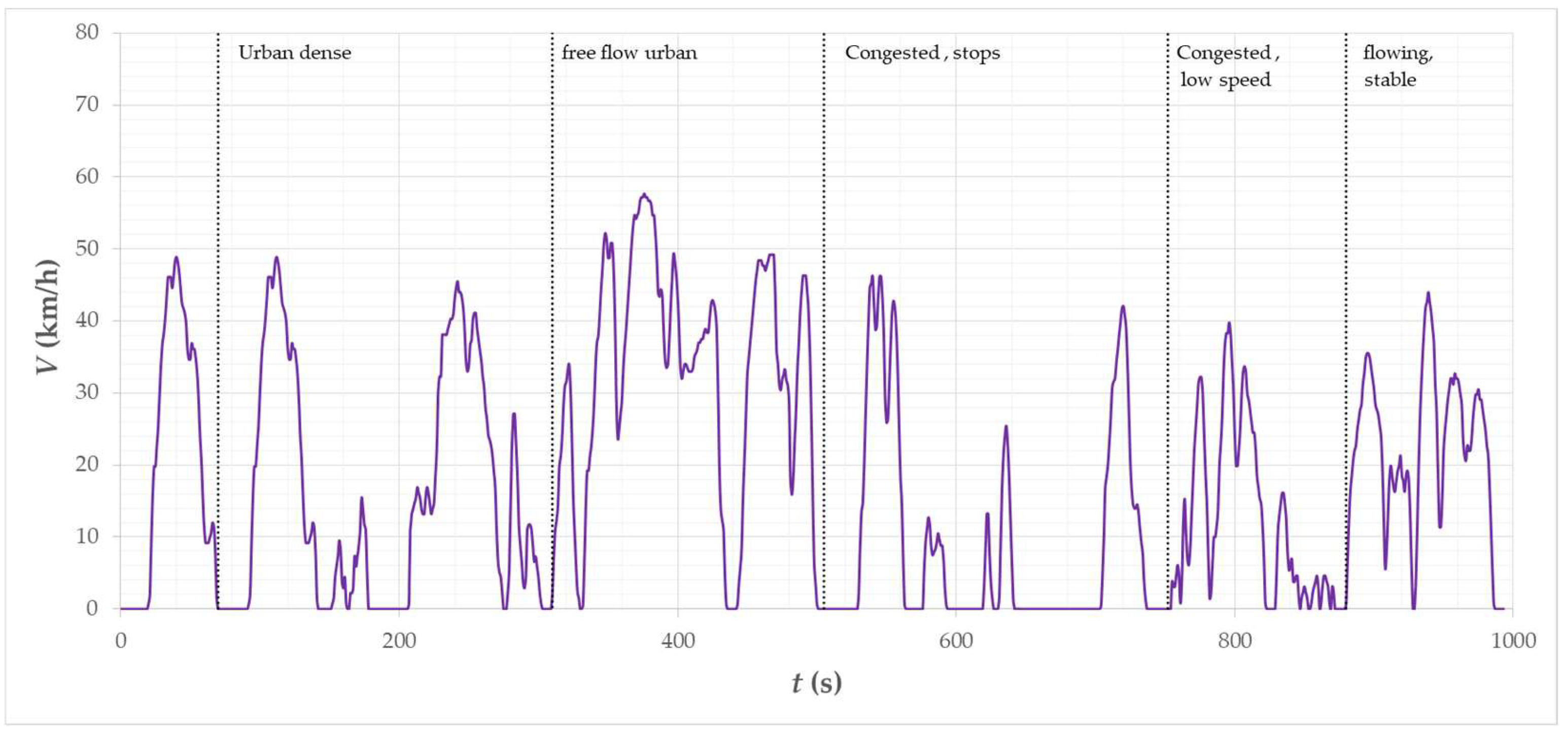
Figure 15 shows the vehicle speed waveform for the Artemis Urban cycle. The waveform consists of certain stages that represent different driving scenarios that affect the driving dynamics of the average driver.
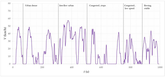
Figure 15.
Vehicle speed waveform of the Artemis Urban cycle.
The first is driving in urban congestion, then driving in a relatively low urban congestion, the third is partial stops due to congested traffic then low speed in congested traffic, and free driving at a relatively constant speed. The maximum vehicle speed equal to v = 57.3 km/h occurs at the stage of driving with a relatively low density of vehicles. The speed above v = 50 km/h is 2% of the entire waveform and occurs only at this stage of the cycle. During the entire driving cycle, stops constitute 21% of the mileage, while 77% is the vehicle’s movement at a speed of up to v = 50 km/h.
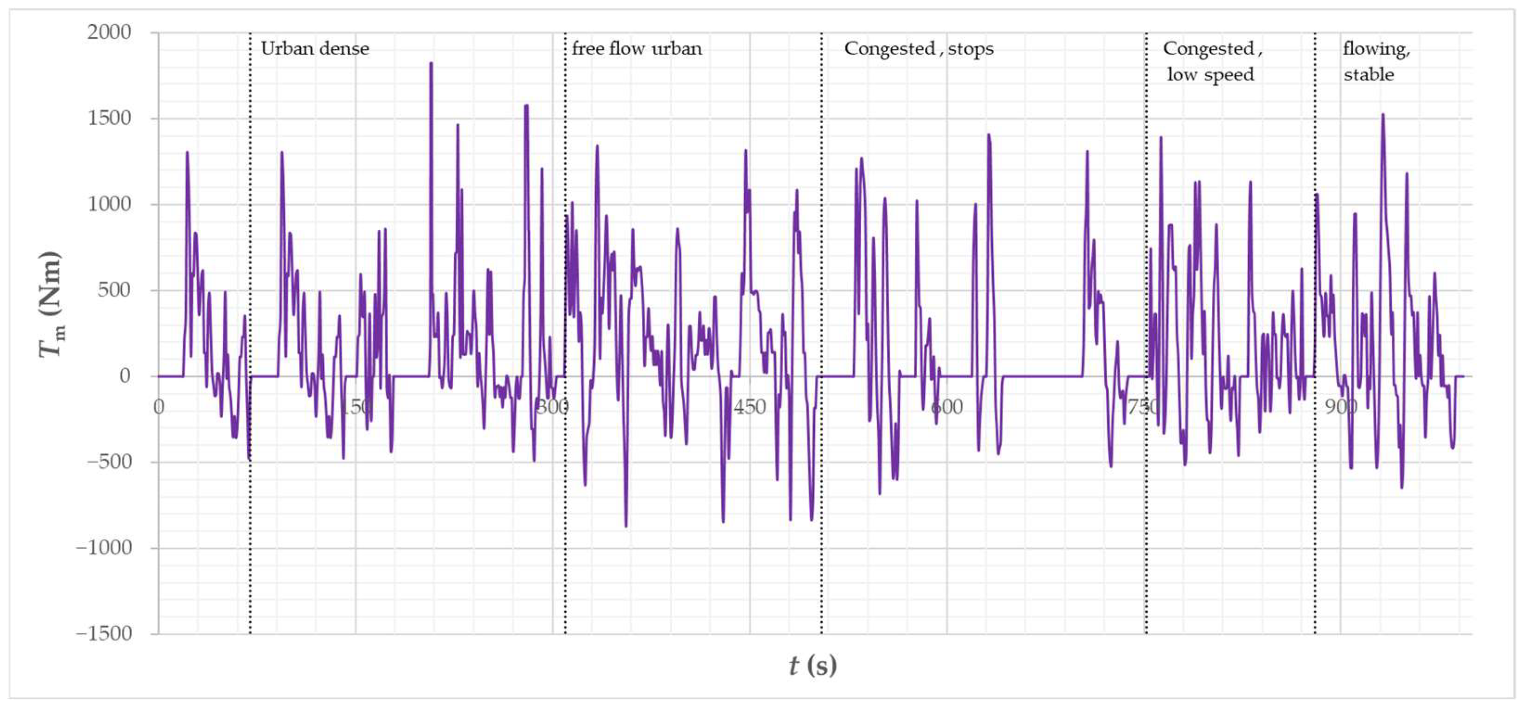
Figure 16 shows the calculated waveform of the required torque, which allows for the completion of the driving cycle of the considered motor, taking into account the vehicle model, operating parameters and temperature of individual motor components. The negative torque is the torque produced by the motor assuming that the motor is providing 25% of the required braking torque. The maximum braking torque is Tm_generating = 872 Nm.
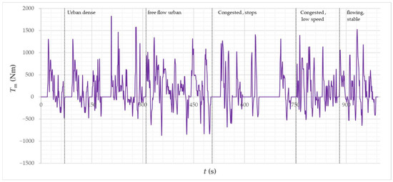
Figure 16.
Vehicle torque waveform of the Artemis Urban cycle.
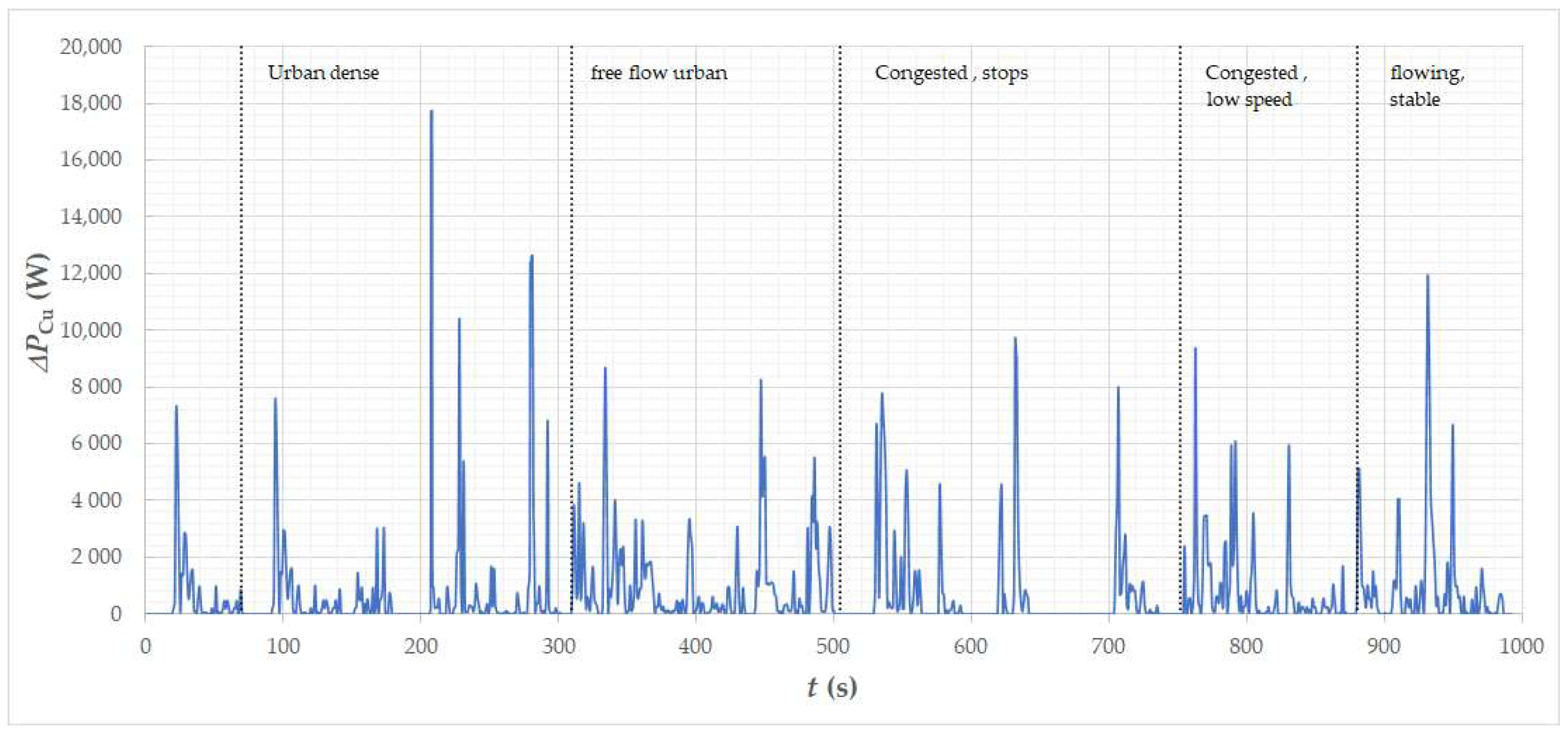
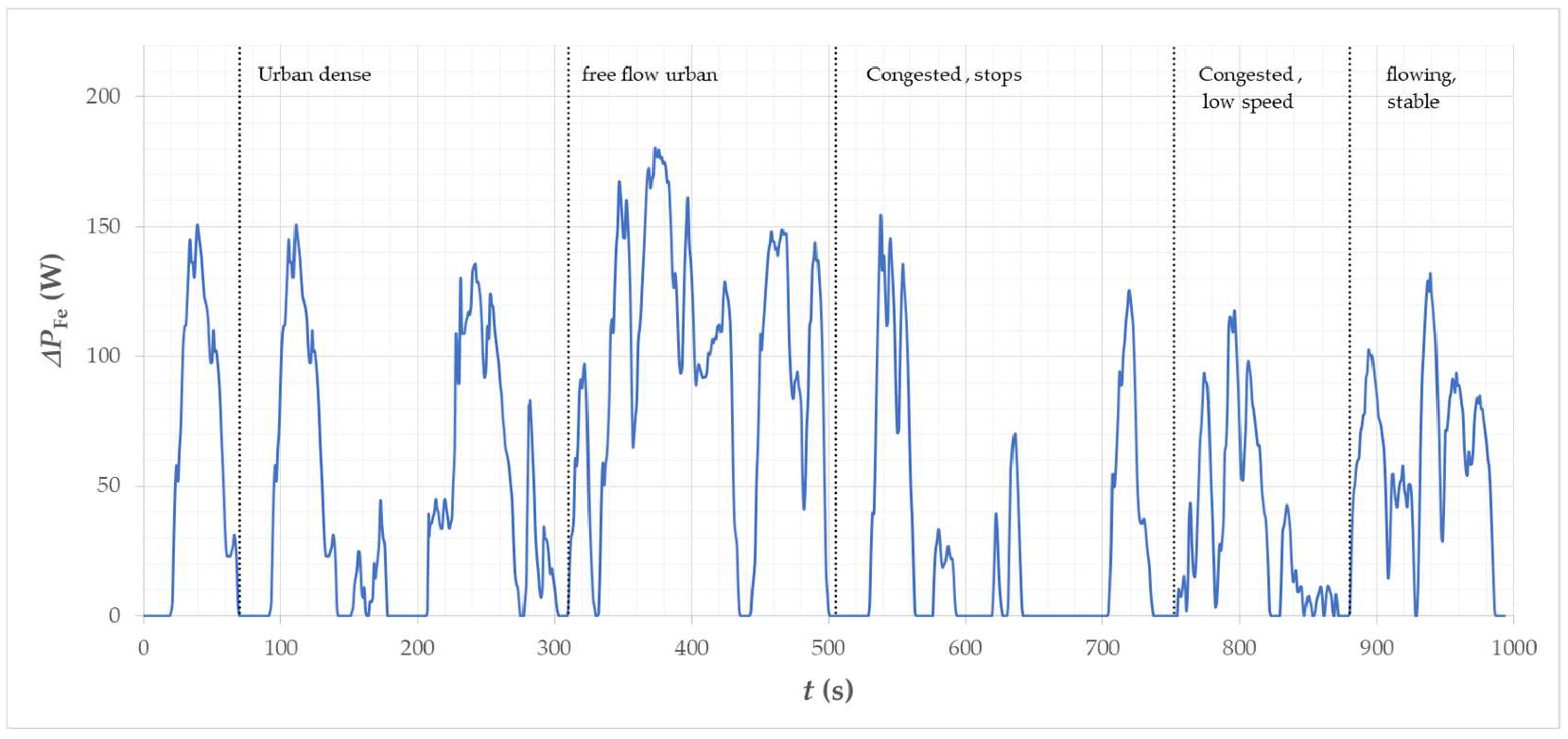
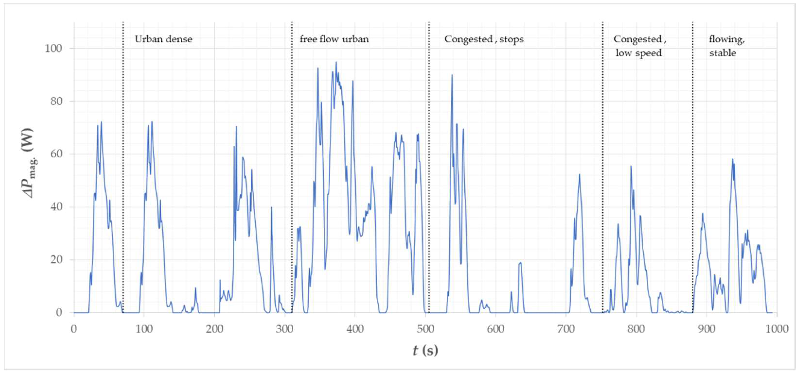
Figure 17 shows the calculated waveform of losses generated in the winding. The highest losses reach temporarily the value of approx. ∆PCu = 18 kW in urban dense. Figure 18 and Figure 19 show the waveform of power losses in the stator magnetic core and in permanent magnets. Losses in the core and in magnets are very similar in nature to the waveform of vehicle speed (Figure 15). This is directly related to the dependence of these losses on the motor operating frequency. The highest losses can be seen in the free flow urban stage, where the car drives at the highest speed and usually only slows down to a slightly lower speed.
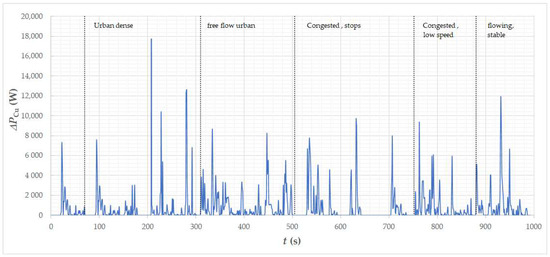
Figure 17.
Calculated waveforms of loss in winding of the motor for the Artemis Urban cycle.
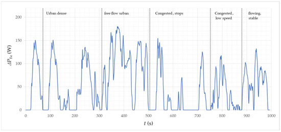
Figure 18.
The calculated waveform of loss in the stator core of the motor for the Artemis Urban cycle.
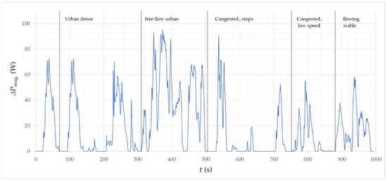
Figure 19.
The calculated waveform of magnets loss in the motor for the Artemis Urban cycle.
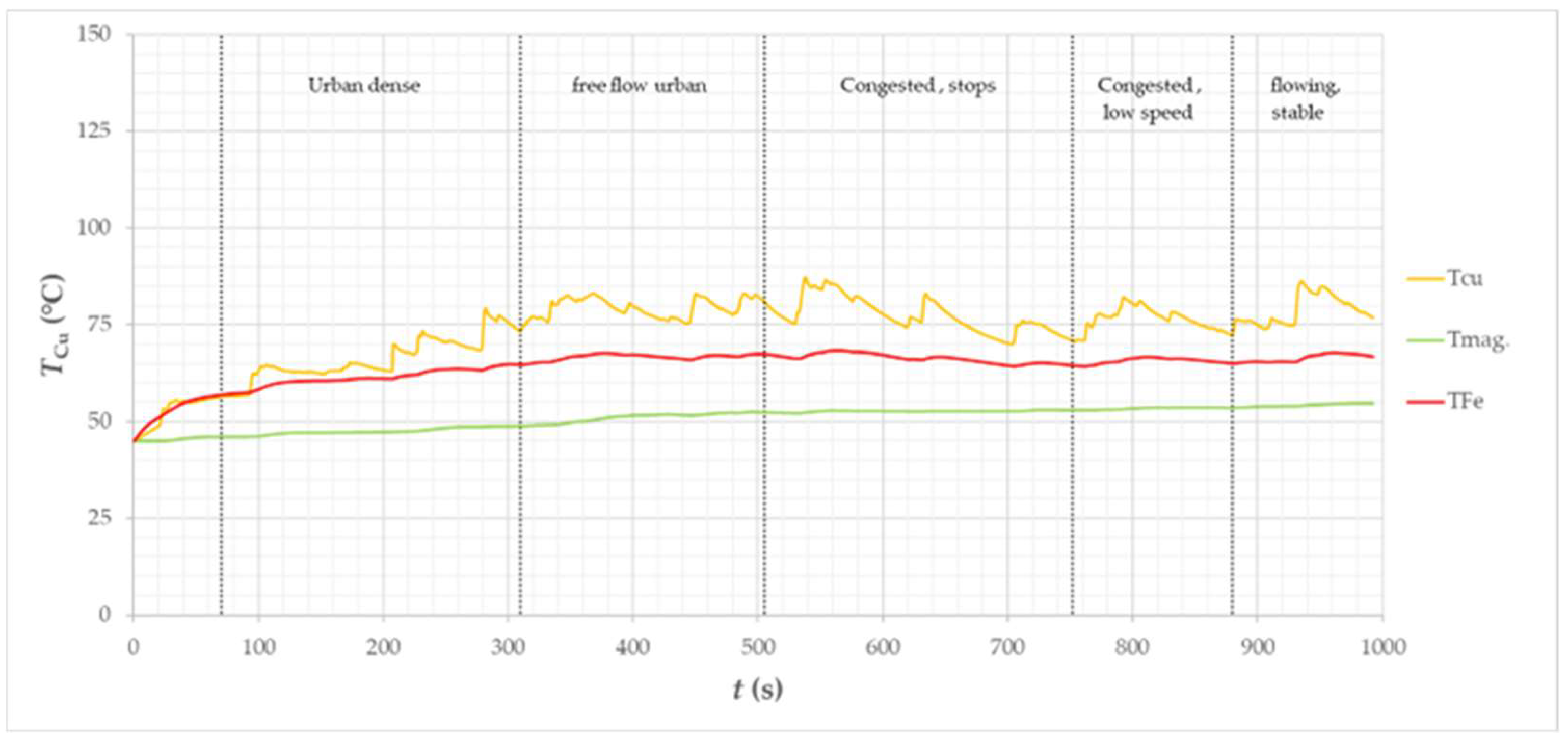
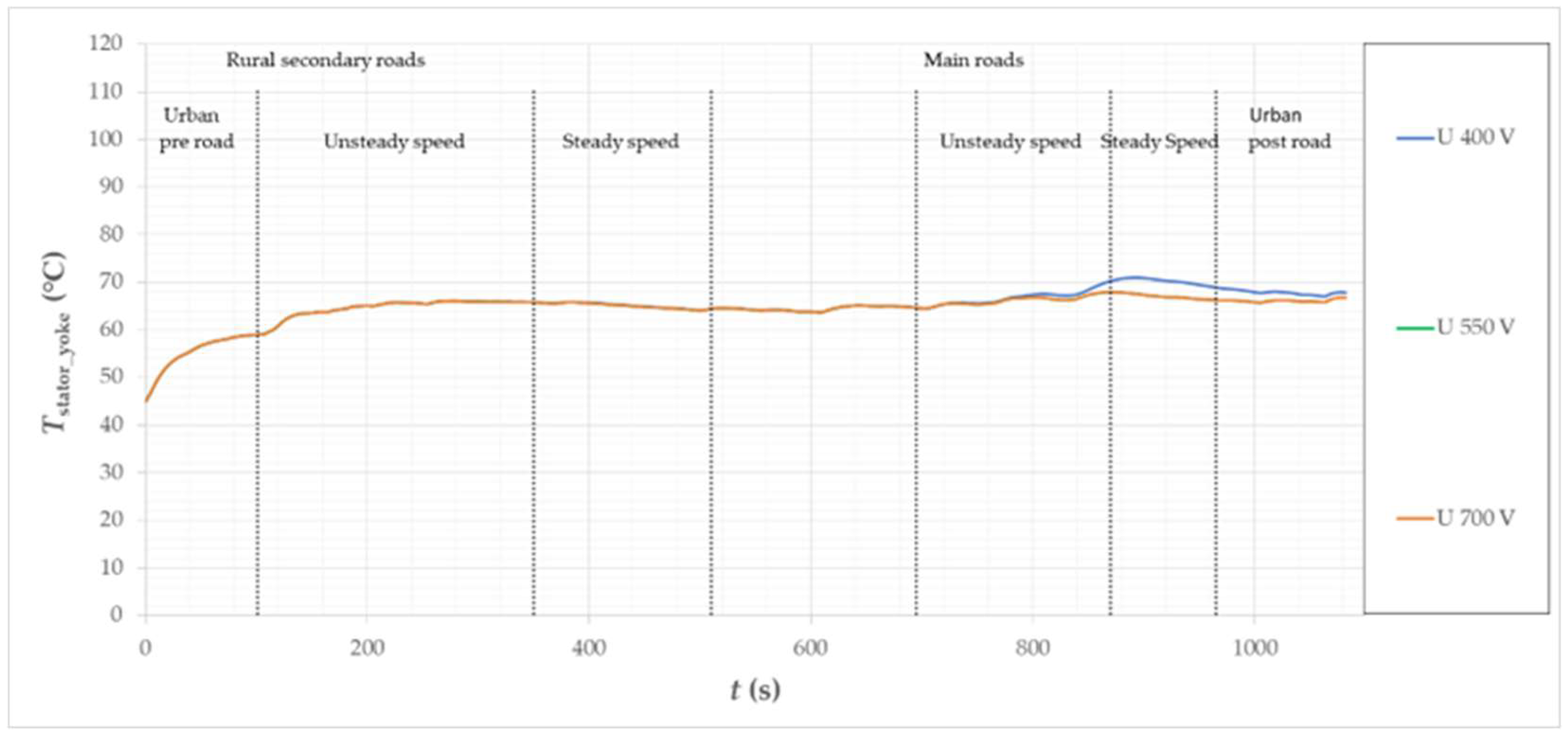
Figure 20 shows the calculated temperature curves at the maximum point of the winding (hotspot), in permanent magnets, and in the stator yoke. The maximum temperature in the motor winding reached safe values at the level of TCu = 85 °C, as was the temperature in Tmag. permanent magnets. = 54 °C. The stator yoke temperature has peaked at Tstator_yoke = 68 °C. The maximum temperature of the winding is important due to the insulation class of the winding wire and the materials to which it adheres, i.e., slot insulation and epoxy resin, in which the winding is potted. The operating temperatures of the insulation, depending on the class, may vary from tz. = 150 °C to tiz. = 200 °C. The epoxy resins used for potting the winding are also characterized by permissible operating temperatures of the order of tepoxy = 180 °C. The working temperature of permanent magnets is normally from Tmag. = 150 °C to approx. Tmag. = 220 °C, assuming that they do not work in an external field that would weaken their work. During flux weakening, the flux from the magnet is weakened, which results in a lowering of the permissible operating temperature. In the case of an urban cycle, the considered motor does not work in the second control zone, so the magnets are not additionally exposed to work in an external, oppositely directed magnetic field.
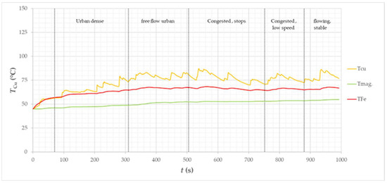
Figure 20.
Calculated temperature curves in the winding (hot spot), in permanent magnets, and in the stator yoke of the motor for the considered vehicle in the Artemis Urban driving cycle.
The temperature of the stator yoke can be important from a technological point of view.
The design of the motor assumes that the magnetic core of the stator is placed on an aluminum support structure with a cooling system. It should be analyzed whether the thermal conditions of the motor do not cause a significant temperature difference between these elements, as this may lead to a significant deterioration of the contact of the elements and deterioration of the efficiency of heat transfer from the stator to the cooling system. In the case under consideration, the temperature of the yoke is only slightly higher than the temperature of the coolant, and the temperature difference between the package and the coolant (Tcoll. = 60 °C) does not exceed the safe value of ∆T = 10 °K throughout the entire course.
The temperature of the stator yoke can be important from a technological point of view. The design of the motor assumes that the magnetic core of the stator is placed on an aluminum support structure with a cooling system. It should be analyzed whether the thermal conditions of the motor do not cause a significant temperature difference between these elements, as this may lead to a significant deterioration of the contact of the elements and deterioration of the efficiency of heat transfer from the stator to the cooling system. In this case, the temperature of the yoke is only slightly higher than the temperature of the coolant, the temperature difference between the packet and the coolant (tcoll. = 60 °C) does not exceed the safe value of ∆t = 10 °K throughout the entire waveform.
6. Driving Cycle Simulation—Artemis Road
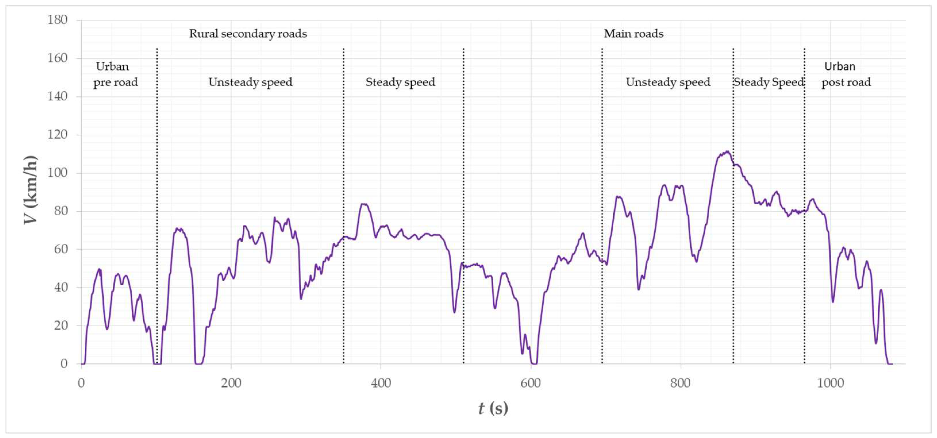
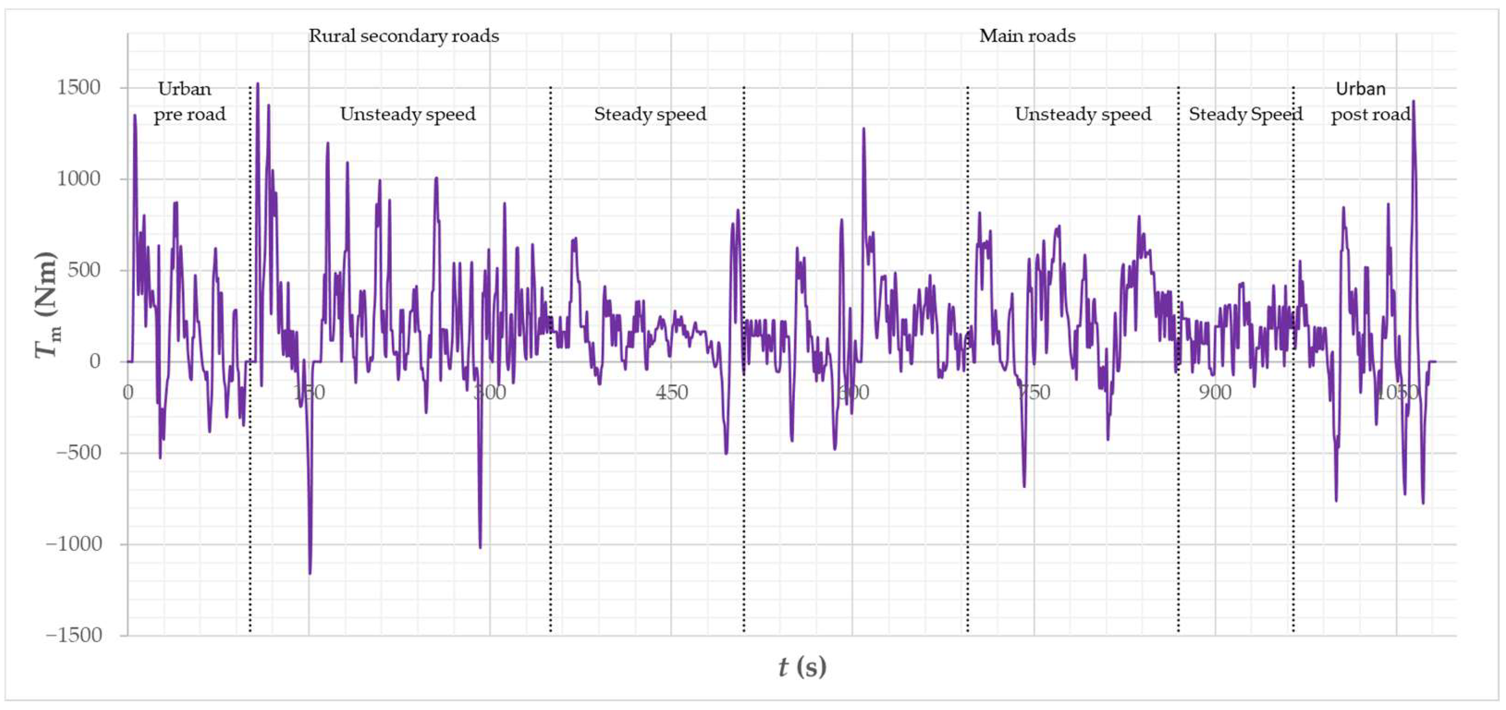
Another cycle under consideration is the Artemis Road cycle. Figure 21 and Figure 22 show successively the waveform of the vehicle speed and the torque generated by the motors, necessary for its implementation with the assumed vehicle parameters. The cycle consists of successive stages divided into two parts. The first part of the stages represents secondary rural roads: urban roads before joining the traffic, driving at an inconsistent speed, driving at a constant speed. The second part of the stage represents the main roads: driving at inconsistent speed, driving at a constant speed, and urban conditions. This driving cycle is dominated by the average speed range of the vehicle (59%) from v = 50 km/h to v = 90 km/h.
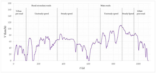
Figure 21.
Vehicle speed waveform of the Artemis Road cycle.
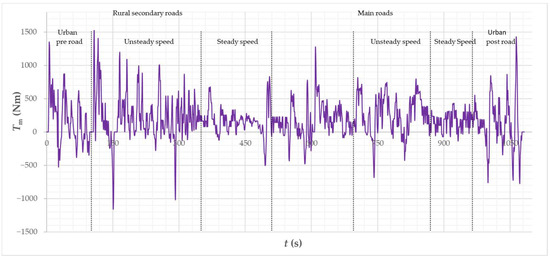
Figure 22.
Vehicle torque waveform of the Artemis Road cycle.
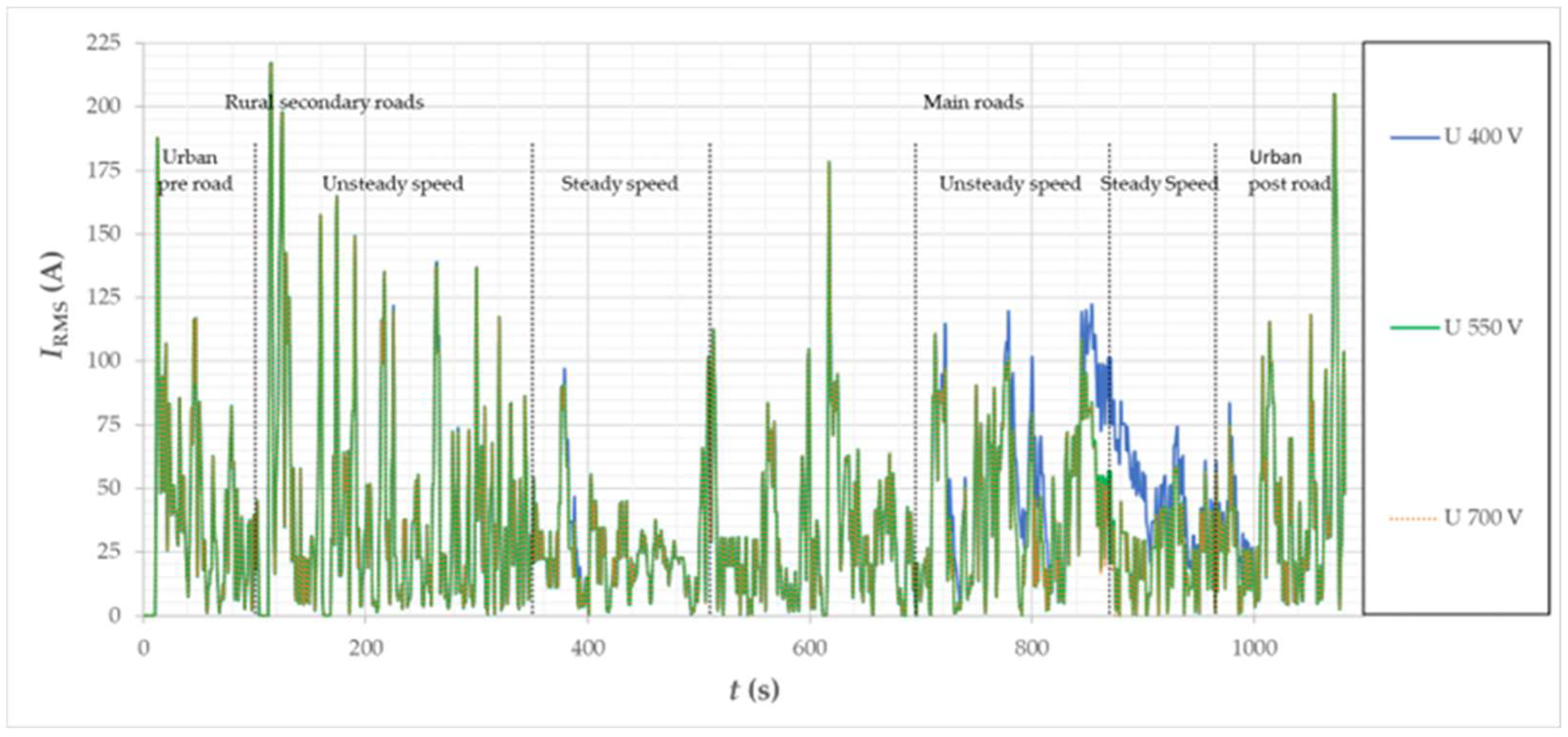
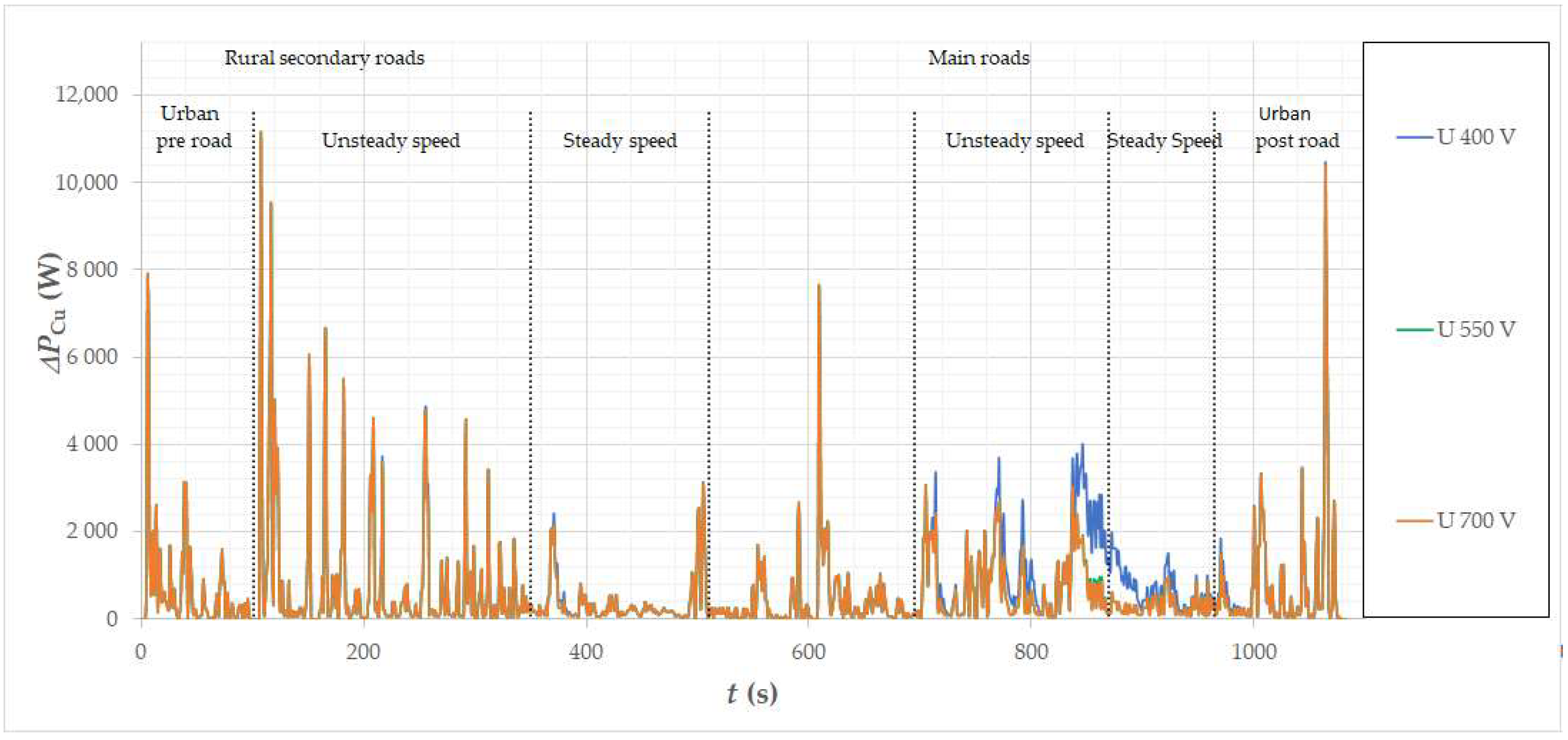
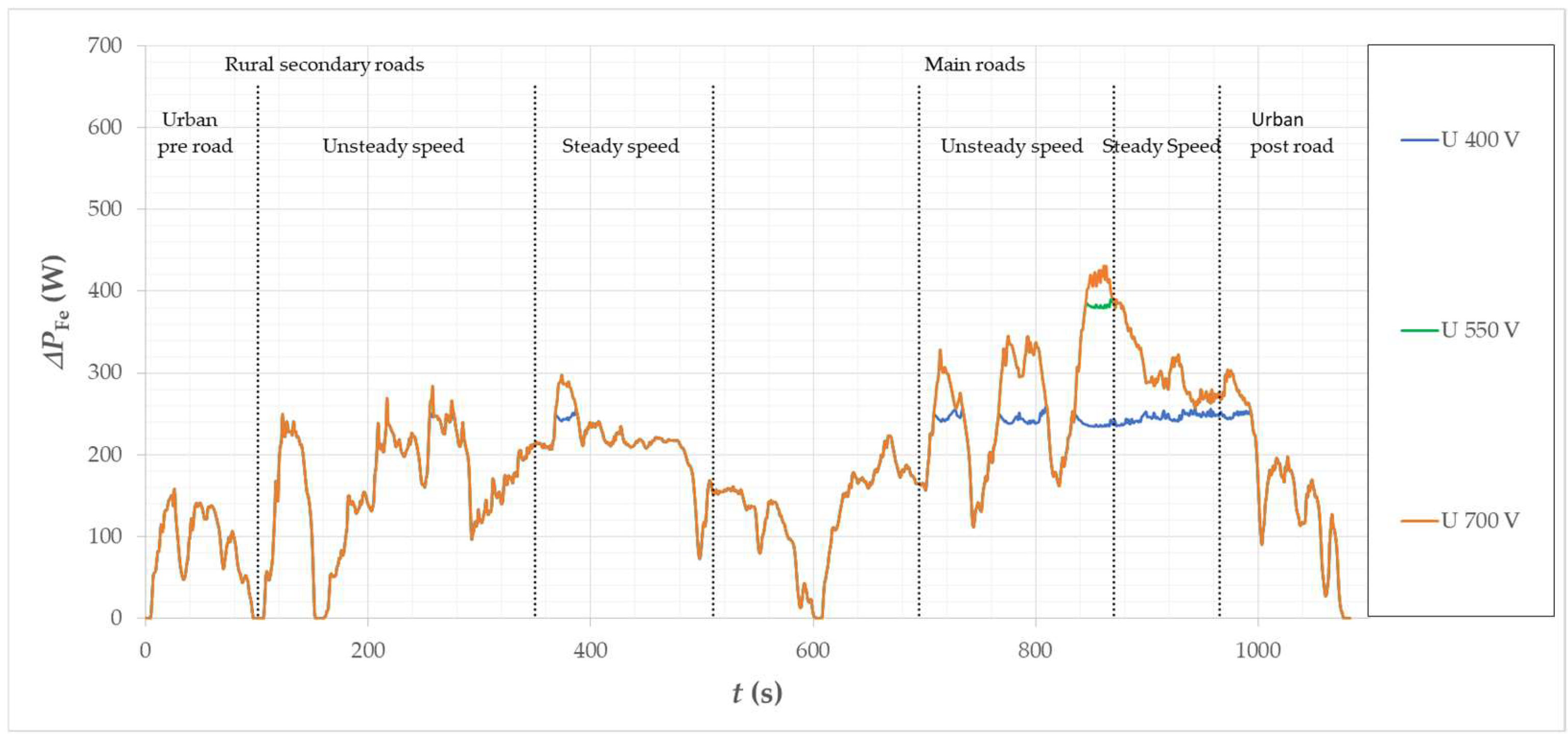
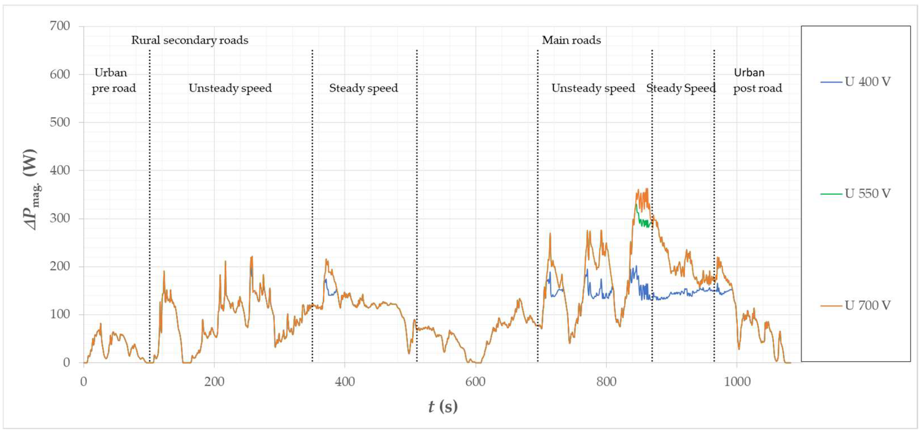
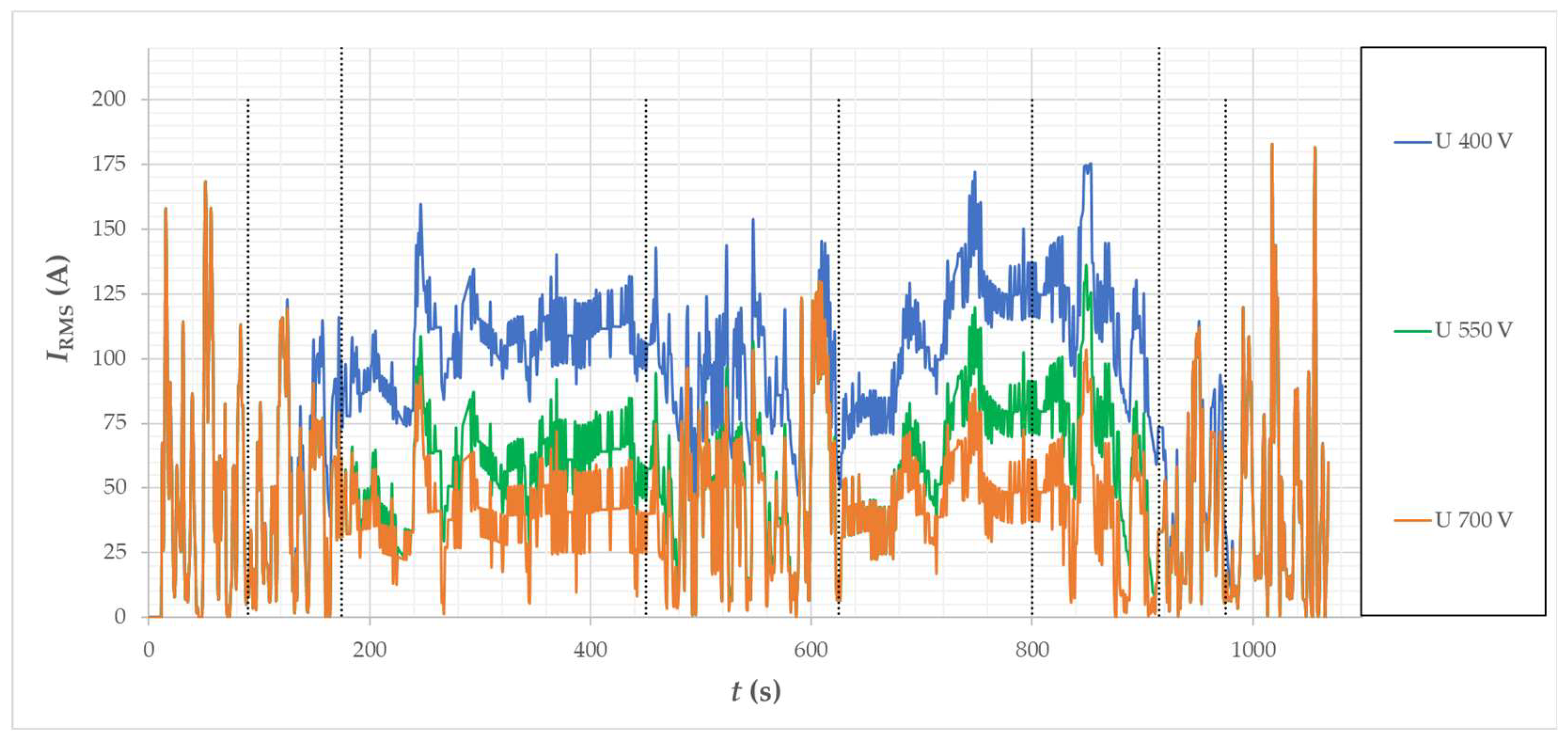
In this driving cycle, the range of the motor’s working area includes to some extent the second control zone. This is clearly visible in the diagram of the supply current (Figure 23) and the power losses generated in the winding (Figure 24) and the power losses generated in the stator magnetic core (Figure 25). In the main roads’ unsteady speed and steady speed stages, the car moves at the highest speed within the work cycle. The torque required in these stages, at this speed, requires flux weakening, which causes an increase in the demand for IRMS supply current at the supply voltage UDC = 400 V and an increase in winding losses (Figure 24). For the voltage UDC = 700 V and UDC = 550 V, the current demand is almost the same. The effect of flux weakening is visible in the loss characteristics in the magnetic core (Figure 25) and in the permanent magnets (Figure 26).
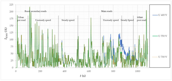
Figure 23.
Calculated IRMS supply current waveforms of the motor for the considered vehicle in the Artemis Road driving cycle.
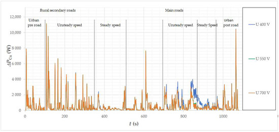
Figure 24.
Calculated loss waveforms in the winding for the considered vehicle in the Artemis Road driving cycle.
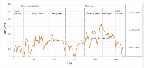
Figure 25.
Calculated loss waveforms in the magnetic core of the motor for the considered vehicle in the Artemis Road driving cycle.
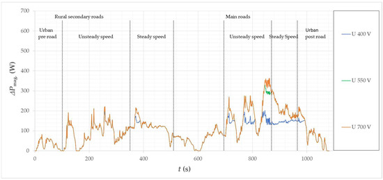
Figure 26.
Calculated loss waveforms in magnets of the motor for the considered vehicle in the Artemis Road driving cycle.
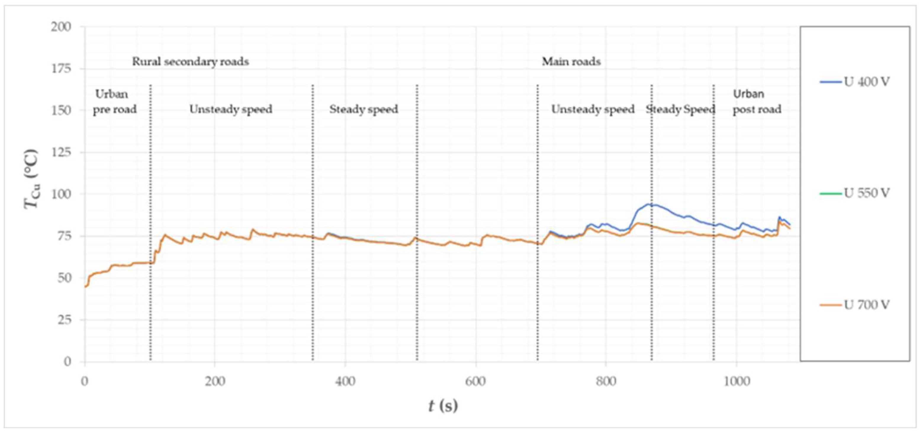
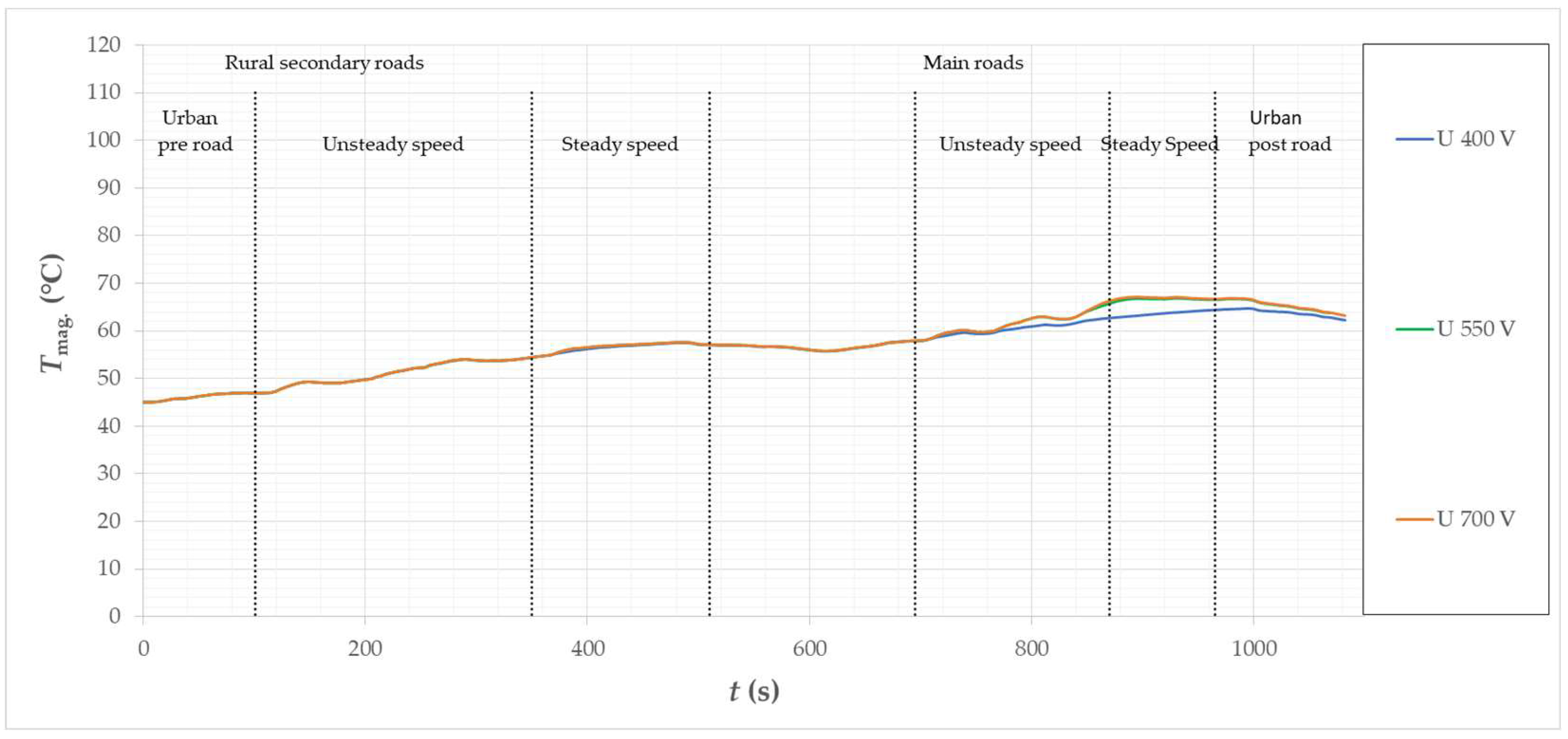
Figure 27, Figure 28 and Figure 29 show the temperature waveform in the winding (hotspot), in the permanent magnet and in the stator yoke. The increase in the supply current when the motor is supplied with the lowest voltage caused a visible increase in the winding temperature, but it is still at a safe level, below TCu = 100 °C. For the same supply voltage, the temperature of the magnets is slightly lower due to the reduced power losses by flux weakning. Despite the reduction of the power loss in the stator magnetic core, the temperature in the stator yoke increased slightly. This is due to an increase in the winding temperature, which has a significant effect on the temperature of the magnetic core, through which it gives off heat to the cooling system. For all power supply cases, the calculated winding, permanent magnet, and yoke temperatures are safe temperatures for the motor operation. The temperature in the magnet does not exceed the Tmag value. = 70 °C. The differences in the operating parameters between the power supply UDC = 550 V and UDC = 700 V are negligible, because at the higher voltage the motor does not work in the second control zone, while at the lower voltage it works to a small extent.
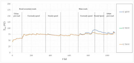
Figure 27.
Calculated temperature waveforms in the motor winding (hot spot) for the considered vehicle in the Artemis Road driving cycle.
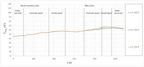
Figure 28.
Calculated temperature waveforms in permanent magnets of the motor for the considered vehicle in the Artemis Road driving cycle.
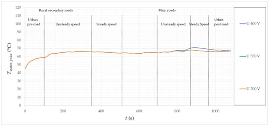
Figure 29.
Calculated waveforms of temperatures in the stator yoke for the considered vehicle on the Artemis Road drive cycle.
7. Driving Cycle Simulation—Artemis Motorway150
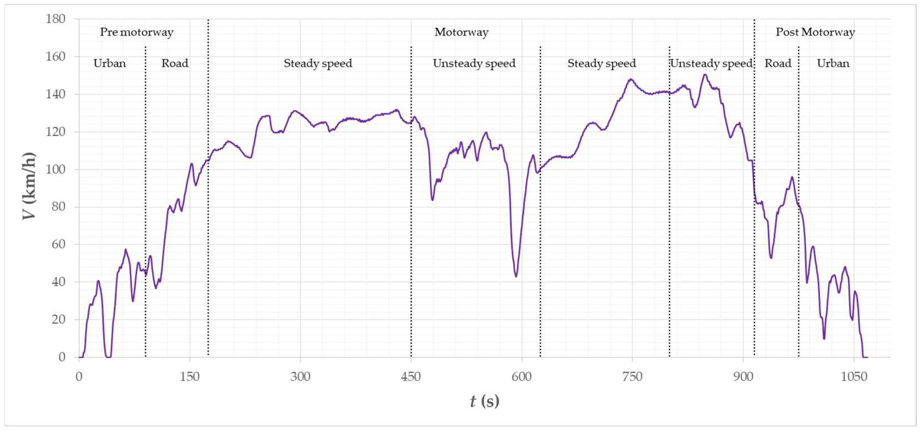
The last cycle of work under consideration is Artemis Motorway150. The cycle represents motorway driving up to v = 150 km/h. The cycle is divided into stages before entering the motorway: urban and road, driving on the motorway: with a constant speed of up to approx. v = 130 km/h, driving at a constant speed up to v = 150 km/h and with a variable when leaving the road to urban.
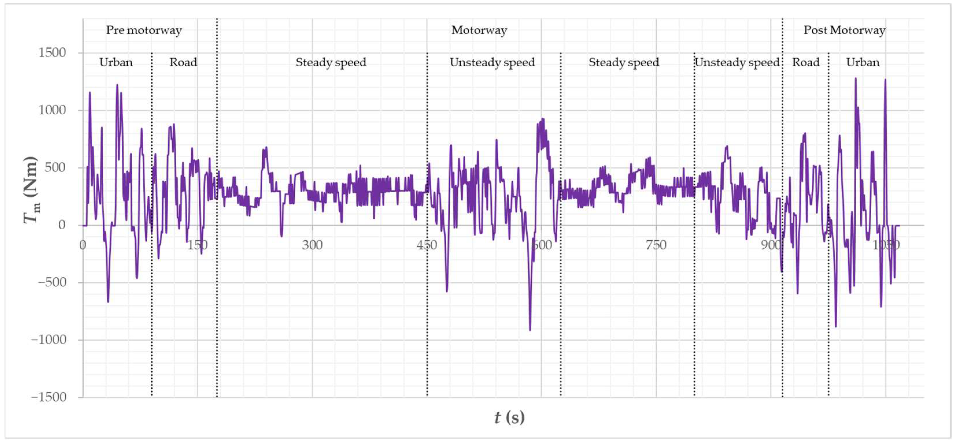
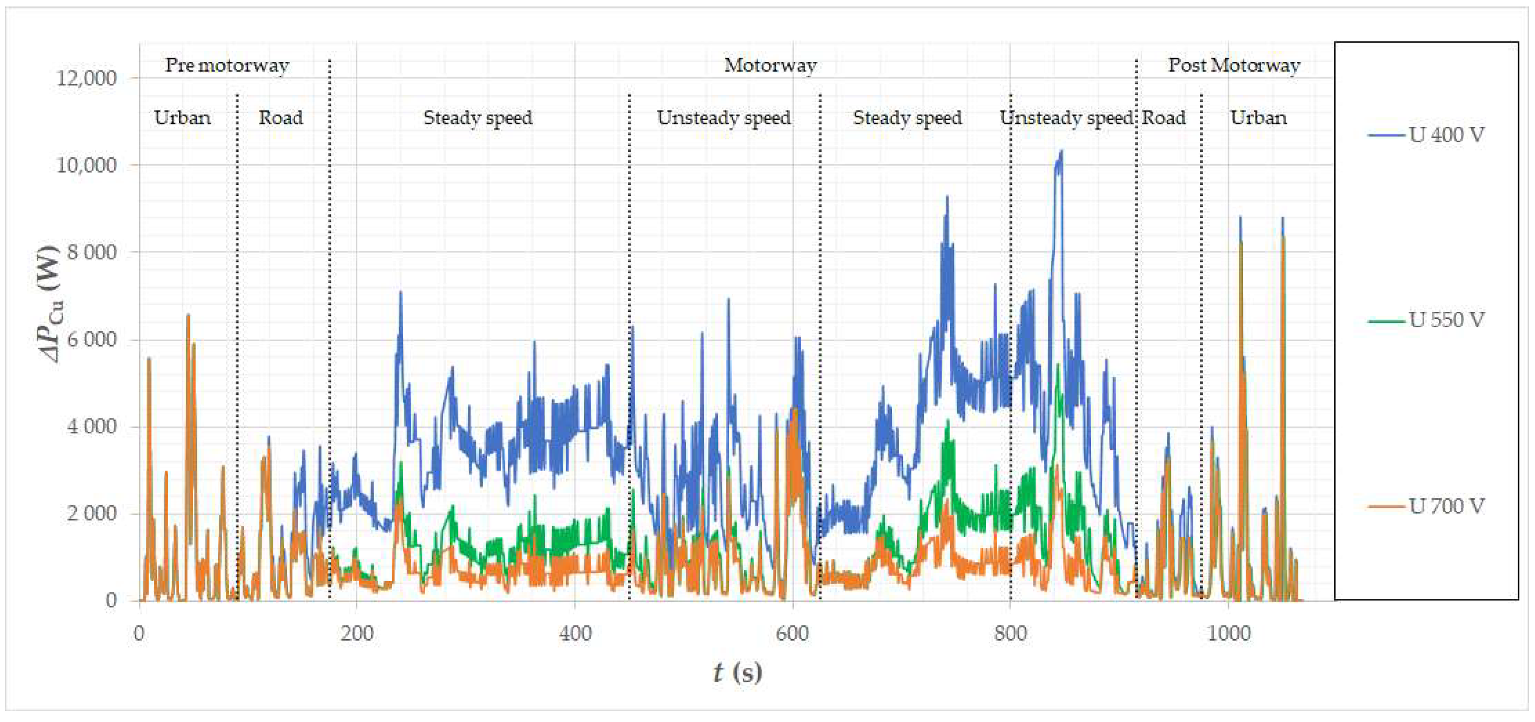
The speed and torque requirements (Figure 30 and Figure 31) make the motor work in the second control zone through all stages of driving on the highway and, similarly to the previous cycle, also to a certain extent on the road. Similar to the results presented earlier, in Figure 32 and Figure 33, waveforms of currents and losses in the motor winding are presented, for supply with three different voltages.
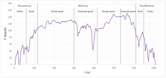
Figure 30.
Vehicle speed waveform of the Artemis Motorway150 cycle.
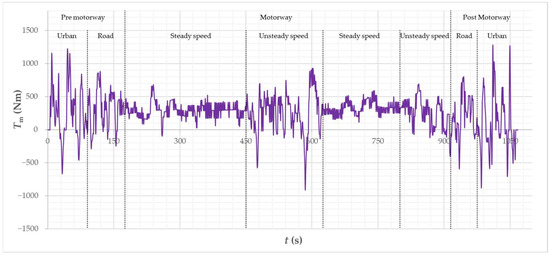
Figure 31.
Calculated vehicle torque waveform of the Artemis Motorway150 cycle.
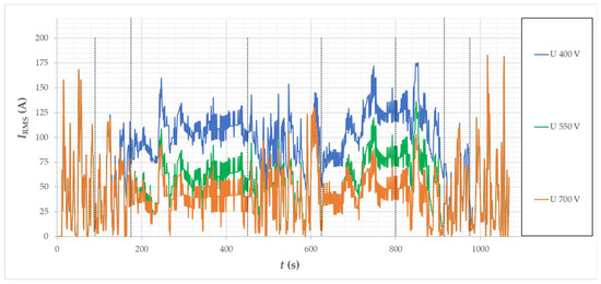
Figure 32.
Calculated IRMS supply current waveforms of the motor for the considered vehicle in the Artemis Motorway150 cycle.
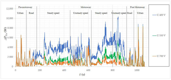
Figure 33.
Calculated loss waveforms in motor windings for the considered vehicle in the Artemis Motorway150 cycle.
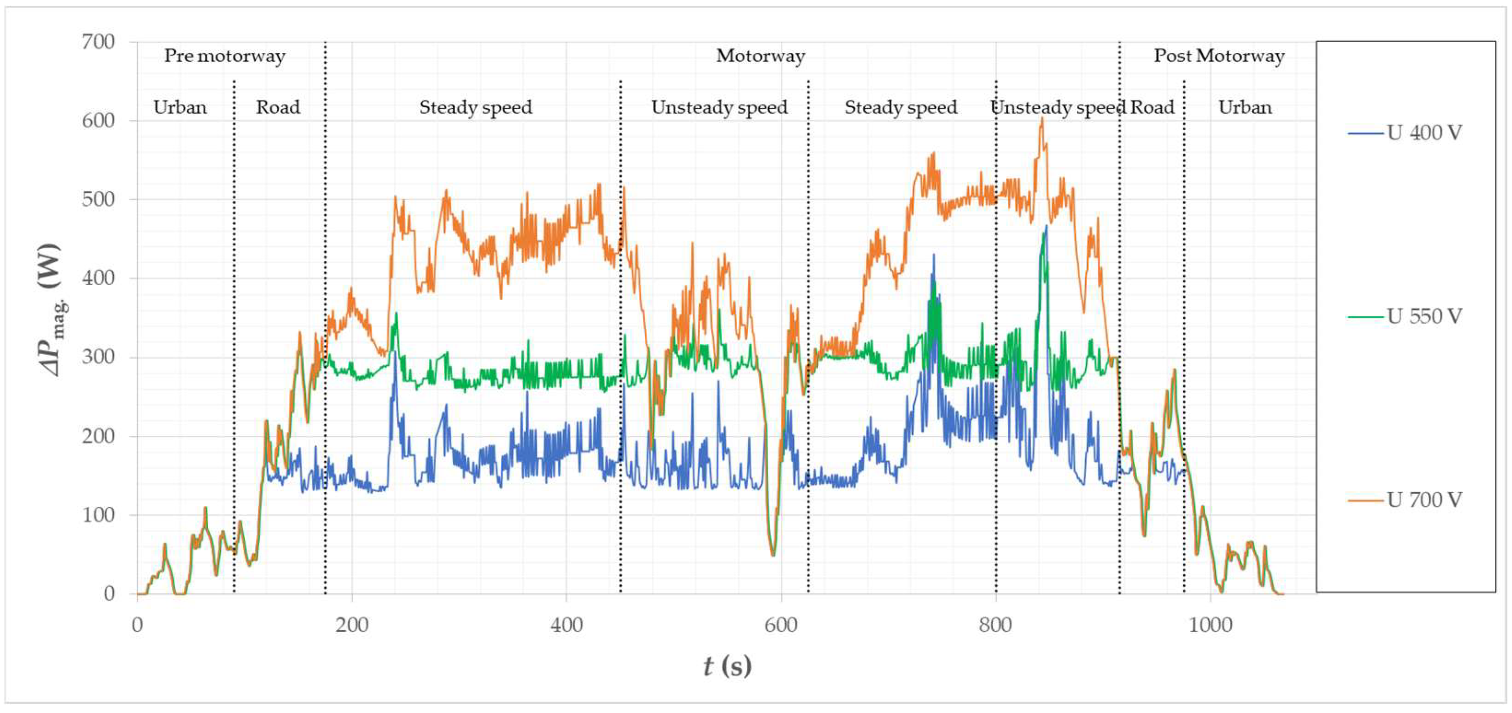
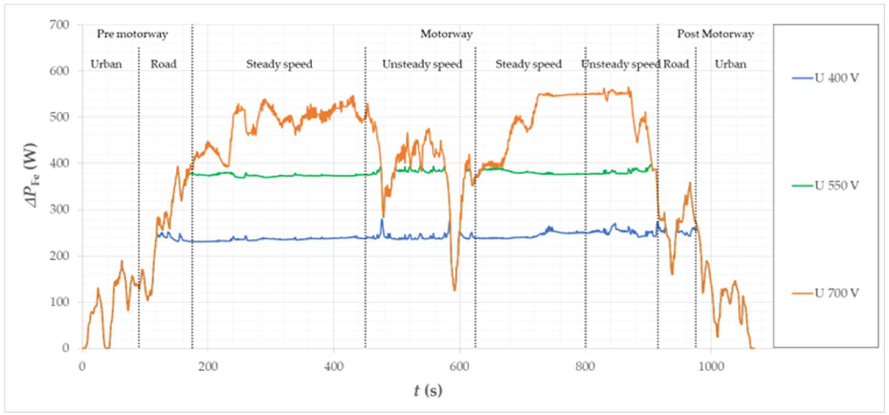
The IRMS waveform shows a large difference in power demand when driving at higher speeds, depending on the supply voltage UDC. The work in the second control zone is clearly visible. Similarly, as the demand for IRMS supply current increases and the supply voltage UDC decreases, the losses in the winding increase, while the losses in the magnetic core and in the magnets are reduced. The differences in the considered losses are relatively large. Between the version with supply UDC = 700 V and UDC = 400 V, the greatest difference in winding losses was ∆PCu = 7 kW in favor of the higher supply voltage. For the same voltages, the maximum difference in the losses in permanent magnets is approx. ∆Pmag. = 350 W (Figure 34), and in the magnetic core of the stator ∆PFe = 350 W in favor of a lower supply voltage (Figure 35). As could be expected, the benefit of flux weakening in the context of the power or efficiency balance does not cover the losses in the winding, which is clearly visible when comparing the loss curves.
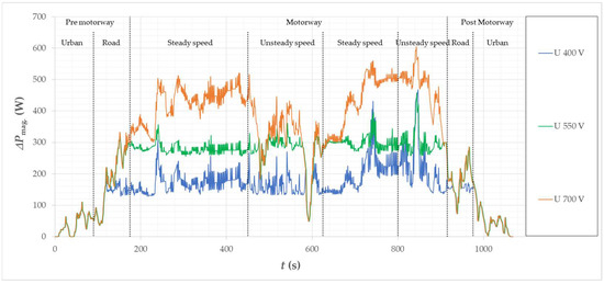
Figure 34.
Calculated loss waveforms in magnets of the motor for the considered vehicle in the Artemis Motorway150 cycle.
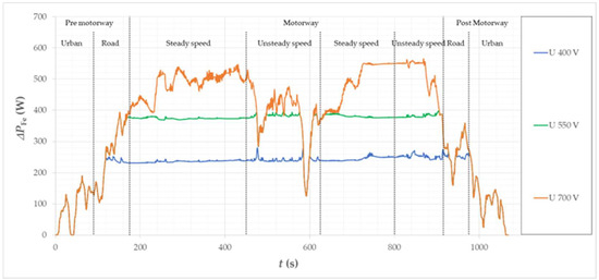
Figure 35.
Calculated loss waveforms in the stator core of the motor for the considered vehicle in the Artemis Motorway150 cycle.
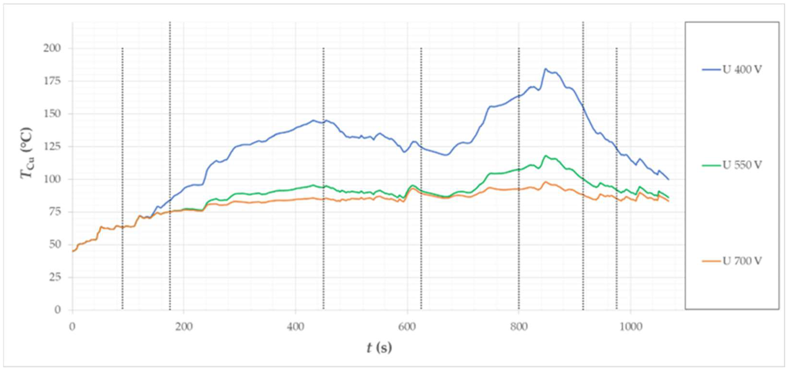
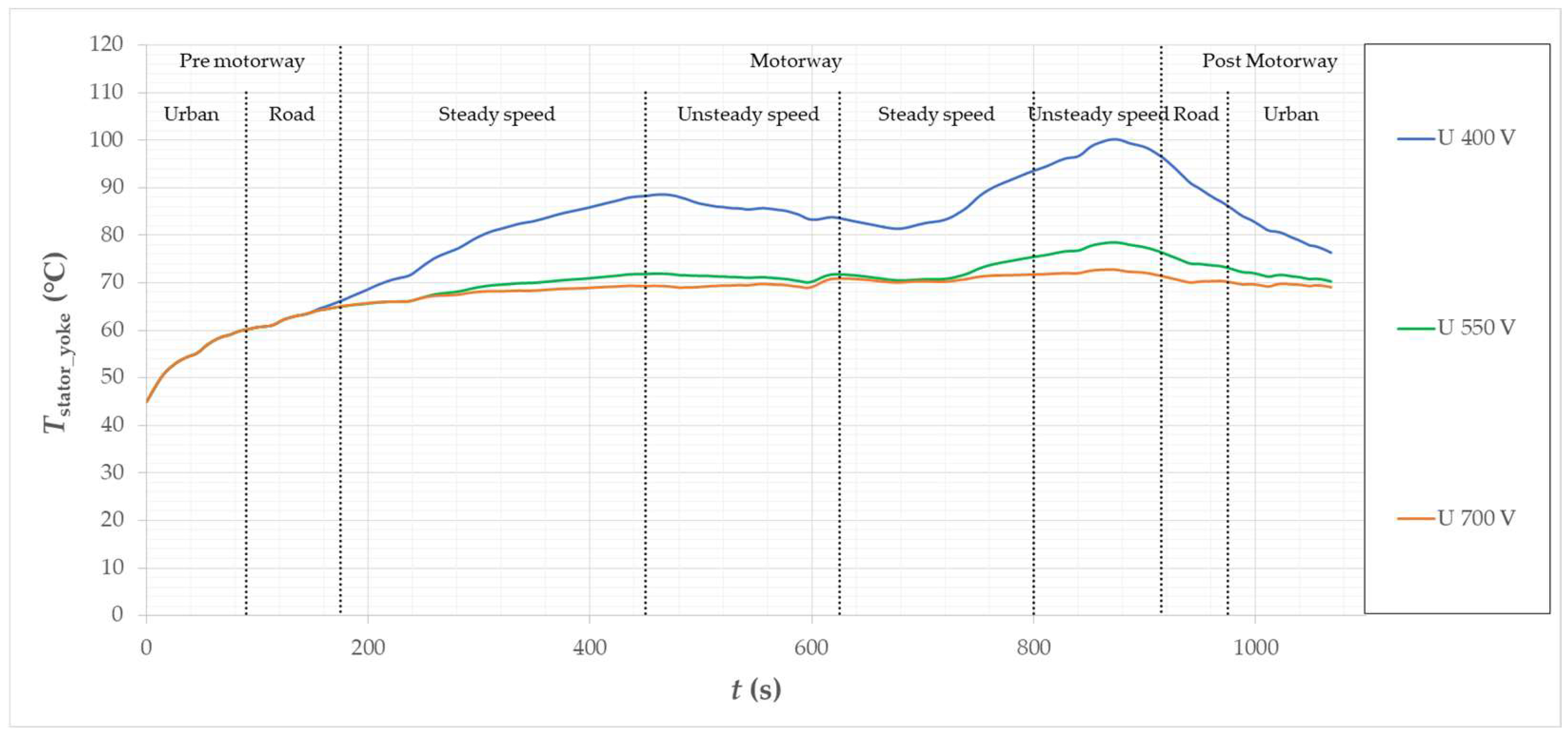
Figure 36 shows a comparison of the hot spot temperature curves in the winding for three supply voltages. When supplied with the voltage UDC = 400 V, the maximum operating temperature of the winding reached approx. TCu = 185 °C. This temperature is relatively high, close to or exceeding (depending on the materials used) the permissible operating temperature of the insulation and epoxy resin. The high temperature of the winding also influences the temperature of the magnetic core of the stator, which, despite the reduced power losses in the second control zone (Figure 37, is high throughout the entire motorway driving range. The presented waveform of temperature and losses shows that before the car enters the motorway, the losses and temperatures of the magnetic core and the windings are very similar for all three supply voltages. The differences appear when the car enters the motorway and the vehicle moves at a higher speed (Figure 37). With increasing speed, large differences in the losses in the winding and in the magnetic core of the stator appear, depending on the supply voltage. Both in the winding and in the stator core, the temperatures increase faster when operated at the lowest voltage. Temperatures and losses are the same after the car exits the motorway. Throughout the run, the maximum stator yoke temperature was Tstator_yoke = 100 °C. The calculated temperature of the supporting structure (on which the stator is mounted) in the active part, i.e., under the lamination core, is ok Taxle = 60 °C, so the temperature difference between the elements is at the level of ∆t = 40 °C. From the calculation of the thermal expansion of the materials, it follows that the equivalent air gap should increase by lstator gap = 0.127 mm. This is a rather safe value because the minimum interference between the stator and the support structure ranges from lstator gap = −0.3 to lstator gap = −0.6 mm. A big threat to the motor operation would be if the increase in the air gap thickness was close to the interference value, because then the contact resistance of the elements would increase significantly and heat dissipation to the cooling system would be much less effective.
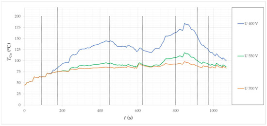
Figure 36.
Calculated temperature waveforms in the motor winding (hot spot) for the considered vehicle in the Artemis Motorway150 driving cycle.
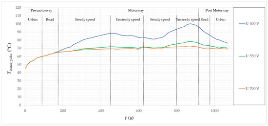
Figure 37.
Calculated temperature waveforms in the motor stator yoke (hot spot) for the considered vehicle in the Artemis Motorway150 driving cycle.
The change in the length of material is assumed to be proportional to the temperature change, as expressed by the formula for linear expansion
where: x—length after temperature change, x0—initial length, α—linear expansion coefficient, ΔT—temperature rise.
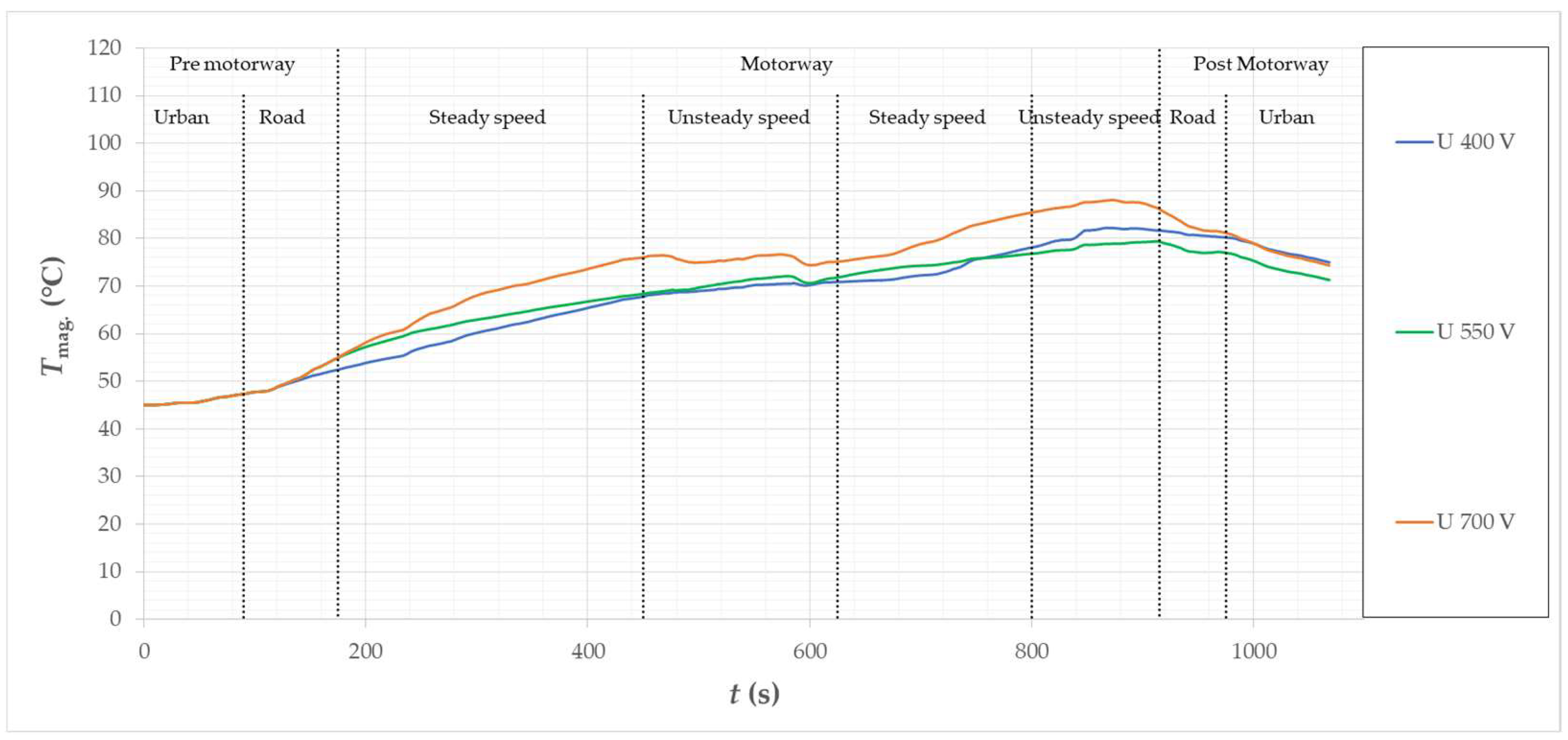
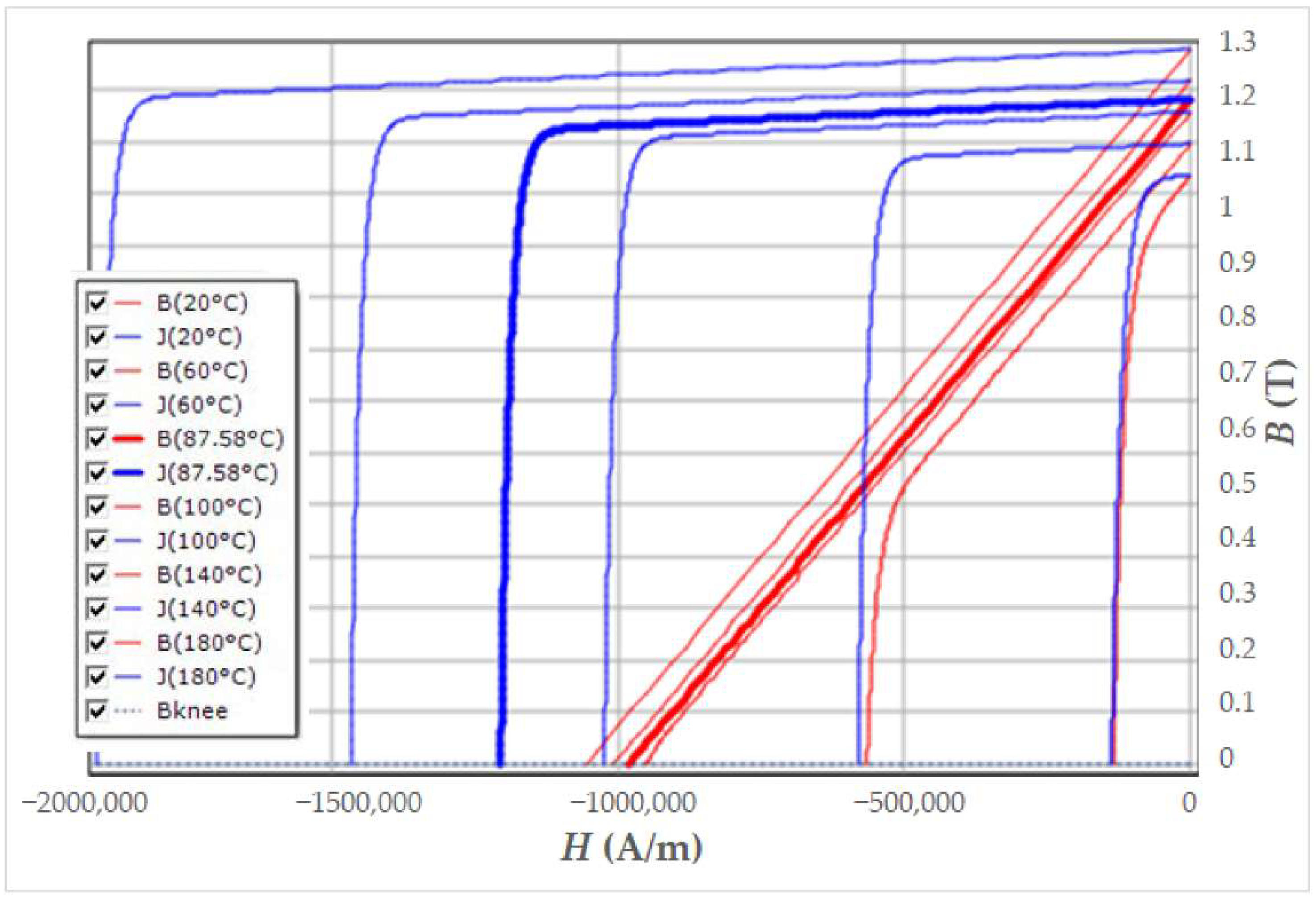
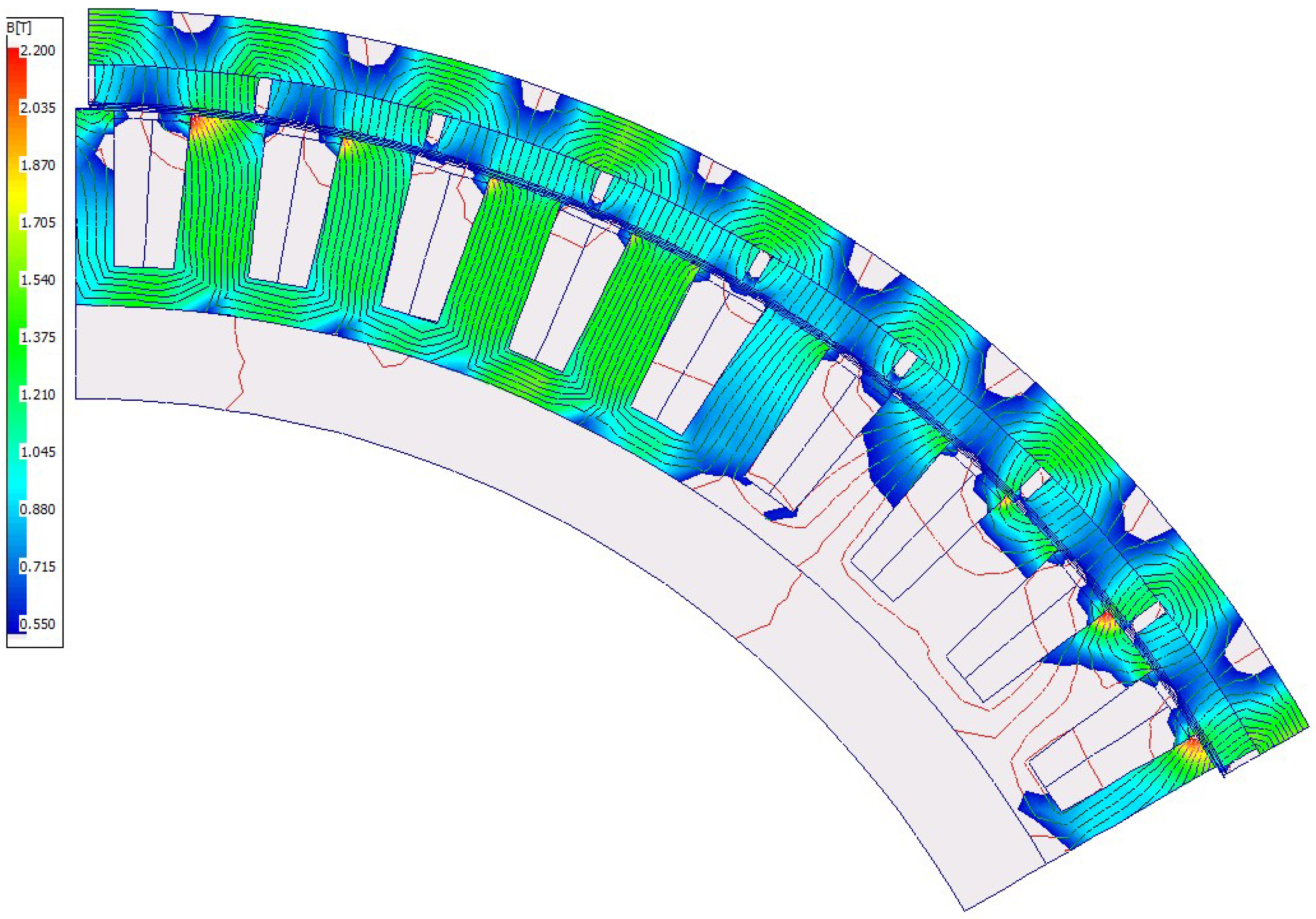
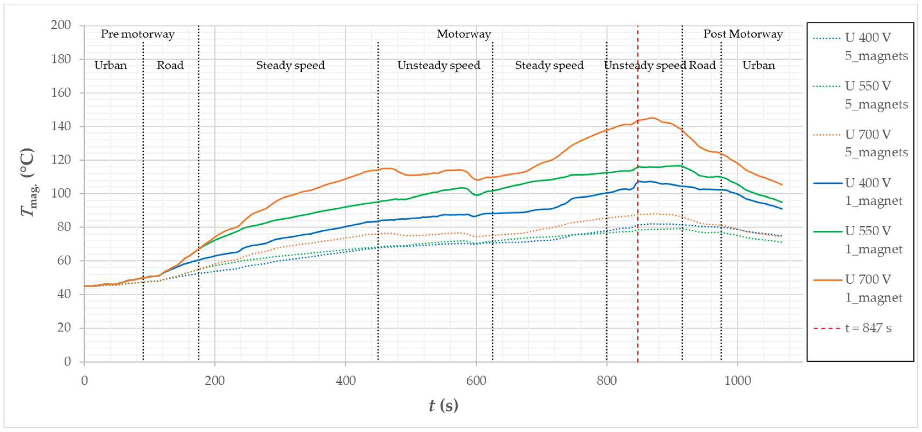
The temperature of the permanent magnets has reached the maximum level equal to Tmag. = 90 °C in the case of the motor supplied with the highest supply voltage considered (Figure 38). This is a safe value, especially since in the case of a motor supplied with the voltage UDC = 700 V, the magnet is under the influence of a lower flux weakning than in the case of lower voltage. The magnet may become partially demagnetized when exposed to a sufficiently high temperature and under the influence of an external magnetic field. Figure 39 shows the demagnetization characteristics of the applied magnets, while Figure 40 shows the distribution of induction saturation at an example position of the rotor at the operating point of the cycle for which the magnet temperature is the highest. The operating point occurs in the 847 s of cycle duration, The car moves at a speed of v = 150.4 km/h (n = 1140 rpm), the motor runs with a torque of Tm = 596 Nm, magnets temperature Tmag. = 87.5 °C, the phase advance angle is equal to αadvance = 27.82°, current Id RMS = 42.98 A, current Iq RMS = 81.46 A. The calculated distribution of induction in permanent magnets for these operating parameters showed that the minimum saturation of the induction in the areas of the magnet is B = 0.55 T. The calculated minimum value of the induction (due to the flux weakening) is dangerous for the magnet only at a temperature of approx. Tmag. = 140 °C (Figure 39).
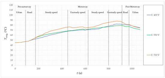
Figure 38.
Calculated temperature waveforms in permanent magnets of the motor for the considered vehicle in the Motorway150 driving cycle.
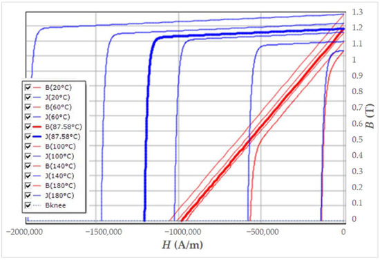
Figure 39.
Demagnetization characteristics of the permanent magnets used in the model.
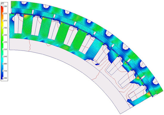
Figure 40.
Calculated magnetic induction distribution of the motor with axial segmentation of magnets (x5) in the 847th second of the Artemis Motorway150 cycle duration with the operating parameters: vvehicle = 150.4 km/h; n = 1140 rpm; Tm = 596 Nm; IRMS = 94 A, αphase advance = 27.8°).
Due to the fact that the temperatures of permanent magnets are at a safe level in all the considered supply voltages, one more analysis has been made to assess the impact of segmentation of the magnets on their operating temperature while driving the car. For this purpose, the construction of the magnet was changed to a magnet without segmentation in the computational model. A simulation of the motor operation was carried out in the Artemis Urban150 cycle, because in this cycle the achieved operating temperatures of the magnets are the highest, and, additionally, the magnets are under the influence of an external, oppositely directed magnetic field during flux weakening.
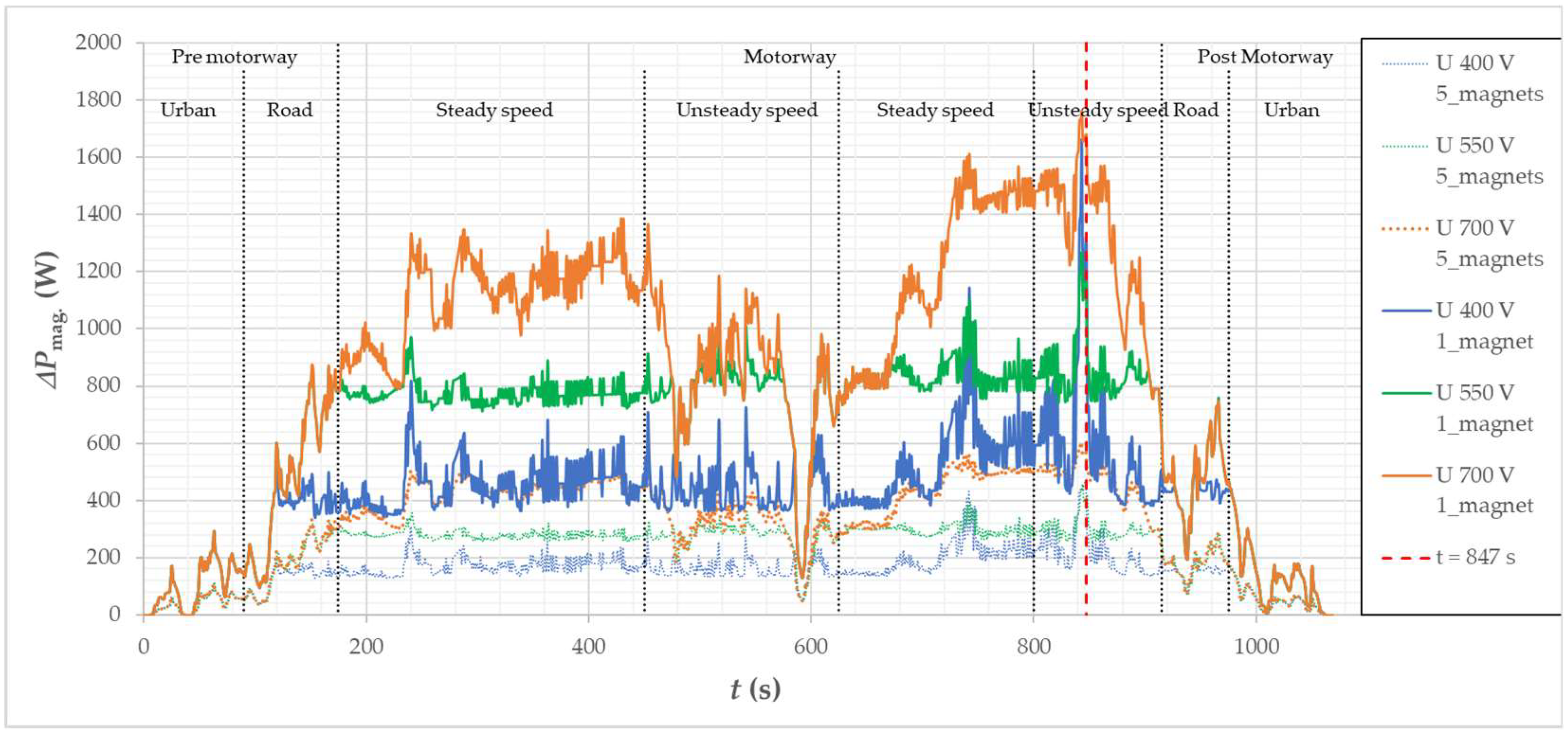
Figure 41 shows the waveforms of the maximum permanent magnet temperatures for the motor without magnet segmentation and with segmentation. As expected, the temperatures achieved are higher due to the increased power losses generated in the magnets. The calculated power losses in magnets were compared for three supply voltages and for the version of the motor with a magnet divided into five segments and without magnet segmentation (1 magnet) in Figure 42 The calculated losses in permanent magnets, in the version without segmentation, are many times higher, which is the reason for the appearance of much higher operating temperatures.
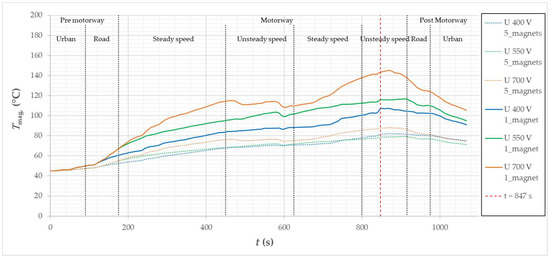
Figure 41.
Calculated temperature waveforms of permanent magnets for three different supply voltages of the UDC drive, for a motor with magnet segmentation (×) and a motor without magnet segmentation.
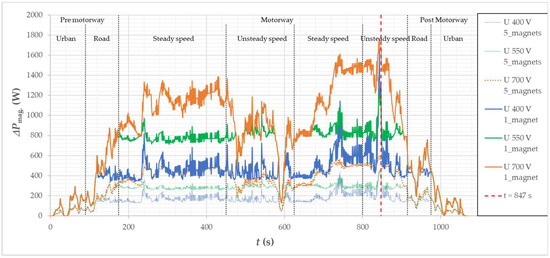
Figure 42.
Calculated loss waveforms in magnets for three different supply voltages of the UDC drive, for a motor with magnet segmentation (×) and a motor without magnet segmentation.
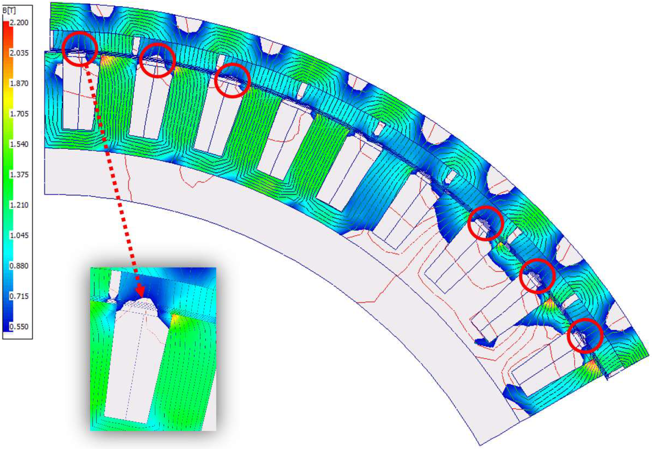
The presented calculation results show that the temperature of the magnets without segmentation when supplied with the voltage UDC = 700 V reaches approx. TCu = 145 °C. This is the temperature of the magnet, reached during the operation of the motor in the second control zone. To compare the motor versions with and without magnet segmentation, the cycle point for the same time instant at high operating temperature for 847 s of cycle duration was compared. Table 4 presents the operating parameters of the considered point. Figure 43 additionally shows the distribution of the magnetic induction saturation field for the same rotor position as in Figure 40. In the case of a motor without magnet segmentation, the induction in the magnets drops below the value of B = 0.55 T in some areas. The areas are marked with red circles. Places with reduced induction are located in the slot area of the magnets. The magnet is operated at a temperature above the Tmag. > 140 °C which, in accordance with the demagnetization characteristics, indicates the possibility of partial demagnetization.

Table 4.
Motor operating parameters in the 847th second of the Artemis Urban drive cycle, with magnet segmentation and without magnet segmentation.
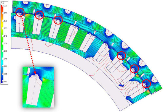
Figure 43.
Calculated motor magnetic induction distribution without the axial segmentation of the magnets, in the 847th second of the Artemis Motorway150 cycle time with the operating parameters: vvehicle = 150.4 km/h; n = 1140 rpm; Tm = 596 Nm; IRMS = 92.26 A, αphase advance = 20.5°).
8. Driving Simulations—Slope
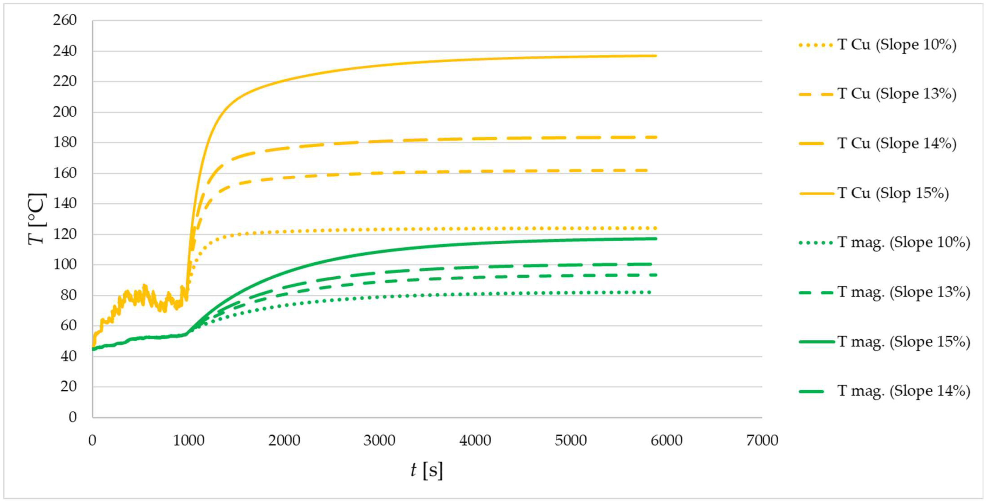
The next research that is necessary to understand the capabilities of the designed motor is uphill driving simulations. While driving, the car may be driven on roads with various types of slopes. Calculations have been made for different percentage slopes. The calculations were carried out so that at the end of the Artemis Urban cycle simulation, in 983 s of the cycle, when the car slows down (Figure 15), the drive begins with constant torque and constant speed v = 50 km/h for slopes up to 15% (Figure 44) and at a speed of v = 30 km/h for higher slopes (Figure 45). For higher slopes, a lower vehicle speed was assumed as more likely when negotiating various ramps in the city. The calculations were made similar to the previous simulation for the maximum mass of the vehicle with a load of m = 3300 kg. Table 5 presents the operating parameters set in the simulation resulting from the vehicle speed.
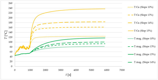
Figure 44.
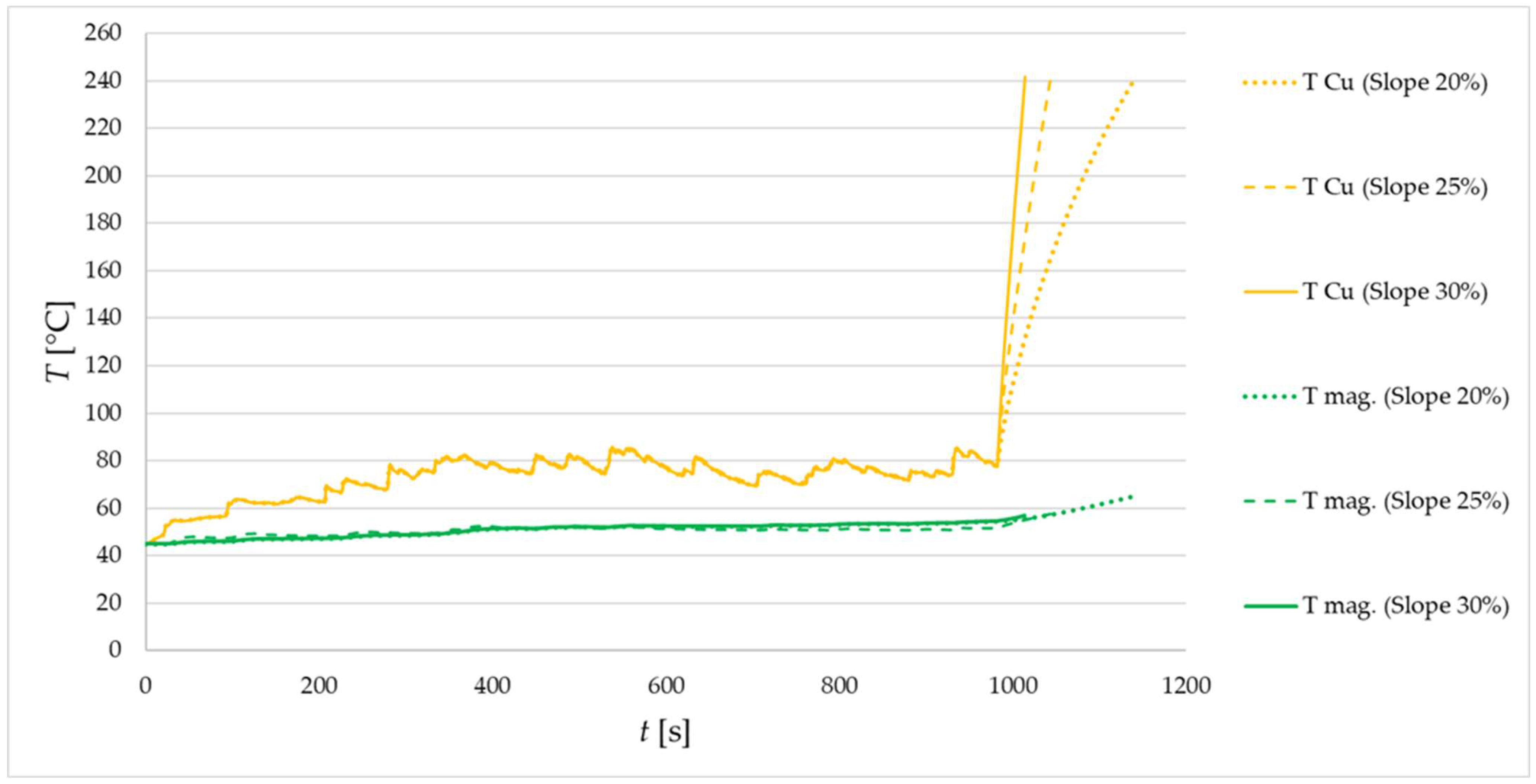
Calculated temperature waveforms of the winding and magnets while driving the car at a speed of v = 50 km/h, on the road with different slopes.
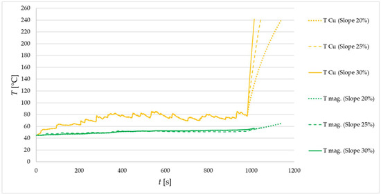
Figure 45.
Calculated temperature waveforms of the winding and magnets while driving the car at a speed of v = 30 km/h, on the road with different slopes.

Table 5.
Calculated motor operating parameters when driving the car on the road with different slopes.
From the presented calculation results, it can be concluded that the drive system of two-wheel hub motors ensures safe, constant driving at a speed of v = 50 km/h on a road with a 13% gradient. The winding temperature is set at approx. TCu = 160 °C. The temperature of the magnets under these operating conditions is set at approx. Tmag. = 95 °C. Both temperatures are safe for long-term operation. With a slope of the route at the level of 15%, the temperature TCu = 160 °C is reached after t = 150 s, while TCu = 200 °C was reached after t = 385 s. It can be concluded that such motor overload is permissible not permanently but until t = 385 s, which corresponds to covering the distance m = 5.34 km. Under this assumption, the temperature of the magnet will not exceed the allowable temperature.
For larger road slopes/gradients, the winding temperature exceeded TCu = 200 °C in all cases. Driving on a road with such a slope/gradient is time-limited, while slopes/gradients are relatively very large, in fact occurring in very limited sections of slopes or on climbs. Under the assumed operating conditions, the permissible maximum operating temperature TCu = 200 °C, when driving on a 30% gradient, will be achieved after driving s = 190 m, which seems to be a good result.
The calculated temperatures indicate that under the considered operating conditions, the winding temperature limits the motor operating time. The temperature of the magnets remains at an acceptable level, assuming that the operating time of the motor will be limited until the winding hotspot reaches the permissible maximum temperature. Demagnetization in such a case is not possible to appear.
Additionally, it should be remembered that the considered drive is hybrid. In cases where the vehicle runs outside the “green zone”, the electric motors may be assisted by the internal combustion engine or completely unloaded.
9. Conclusions
The analysis of the motor operation, in the assumed drive, consisting of two-wheel hub motors, installed in the rear drive axle, allowed us to consider its parameters in various conditions, while driving the car. At the stage of designing the drive and the electric motor, especially those of atypical design, it is important to have a broad look at the possible scenarios of the work regimes in which the motor will work. The analysis assumed that the motor structure fills the entire available area in the rim and that the motor will be tested for three different driving cycles: city driving, suburban driving, and highway driving. The variables were the battery supply voltage and the maximum power consumed by the two electric motors.
The specification of the maximum torque requirements at a given rotational speed in a given driving cycle allowed for the presentation of the wheel hub motor’s operating range in the proposed drive configuration and for the analysis of its power parameters (supply voltage, power demand).
The analysis presents the methodology of the approach to designing the power supply system and designing the power supply system as well as selecting the supply voltage and designing the motor, taking into account the operating conditions encountered in traction applications.
The simulation tests carried out have shown that for driving in the city cycle, the battery voltage UDC = 400 V is a sufficient voltage. The operating temperatures obtained are much lower than the permissible for permanent magnets, windings, epoxy resin, and for the lamination core (in this case, the difference between the temperature of the lamination core and the supporting structure on which it is mounted is limited). The achieved maximum operating temperatures are so small that in the event of limiting the drive operation to the considered cycle and rotational speed range, it is possible to consider shortening the motor magnetic core lamination with a simultaneous increase in the number of turns to the value ensuring unchanged maximum torque. You can also consider reducing the supply voltage. In the urban cycle, the guarantee of maximum power for two motors, at the level of PIN = 120 kW, is a sufficient value with a large margin at low rotational speeds, where the cycle requires relatively large torques and with a very large excess (unnecessary) at higher rotational speeds, where required the torque is relatively small.
In the road cycle, despite the need to work the wheel hub motor partially in the flux weakening zone, the temperatures achieved are also safe and do not come close to the maximum permissible. The demand for power increases significantly. The PIN value of 120 kW is somewhat insufficient at lower vehicle speeds and has no reserve at higher speeds.
In the case of driving on the highway, the achieved operating temperatures of the winding, when supplied with voltage UDC = 400 V, are much higher, equal to or close to the maximum permissible. The temperature of the magnets remains at a safe level, as is the temperature of the magnetic core yoke (depending on the manufacturing technology and the pressing of the laminated stack/core/package onto the supporting structure). The high operating temperatures of the winding are caused by the necessity of a fairly deep flux weakening of the motor and the related increase of the motor supply current. Increasing the supply voltage causes the operating range in the second control zone to decrease so that the winding temperature is within safe limits. The higher the supply voltage, the lower the winding operating temperature in the motorway cycle. Increasing the supply voltage even to the value of UDC = 700 V and a very large reduction in the flux weakening zone resulted in an increase in the power generated in the magnets, but it did not increase the operating temperature of the magnets to a dangerous value.
Due to the relatively low operating temperature of the magnets in all three driving cycles, an additional simulation of the wheel hub motor operation was performed for the highway cycle without magnet segmentation. Segmentation of the magnets involves additional production costs of the magnets themselves and the manufacture of the rotor.
The simulations of the motor operation have shown that when using a magnet without axial segmentation, when the motor is supplied with the voltage of UDC = 700 V, a very large increase in power losses in the magnets will result in an increase in the operating temperature above the Tmag temperature. > 140 °C. Additionally, according to the simulated driving cycle, the magnet is under the effect of flux weakening during this time. The analysis of the distribution of the magnetic induction field showed that at this temperature in certain areas the magnet becomes demagnetized. Lowering the operating temperature of the magnets for this operating point can in this case be achieved by using the weakening of the magnetic flux in the second motor control zone, which can be seen in the example of the supply voltage UDC = 400 V, but as before it is associated with an increase in the supply current and an unacceptable increase in the winding temperature.
The use of the supply voltage UDC = 550 V makes the temperature of the magnets at this operating point slightly safer, while the winding temperature is at a safe level.
In summary, simulation studies have shown that magnet segmentation is necessary to ensure the safe operation of the motor in the highway cycle.
The designed electric motor meets the requirements of the car operating cycles described in the literature. A vehicle equipped with the designed electric motors can move with a full load in urban and suburban areas without the support of the internal combustion engine. Motorway driving is also possible if the drive is configured with a higher supply voltage. If laboratory and road tests confirm the thermal load of the motor in various road conditions, then it is possible to consider reducing the size of the motor or increasing its operating range for driving on the highway.
In the next publication, the authors plan to present the results of laboratory and traction measurements of the prototype wheel hub motor. If the measurements of the motor confirm the large temperature reserves shown by simulation tests, a new wheel hub motor will be designed and built with an improved structure with improved technical parameters and reduced weight.
Author Contributions
P.D.-Development of computational models, running simulation, designing electromagnetic circuits, analysis of simulation results, preparation of the article, description and presentation of control methods, help in the analysis of the results. J.M.-Description and presentation of control methods, help in the analysis of the results, editorial article. R.K.-Analysis of simulation results, participation in the creation of proposals, editorial article. All authors have read and agreed to the published version of the manuscript.
Funding
The project “Polish electric drive solutions in wheels” (“4WHED”) implemented in the Łukasiewicz Research Network is financed under specific subsidies by the Ministry of Science and Higher Education (POLAND) Number: 2/Ł-KOMEL/CŁ/2021. The research is a continuation of the project “Innovative Solutions for Direct Drive of Electric Vehicles”, financed by National Centre for Research and Development under the LIDER VII program, in accordance with the agreement: LIDER/24/0082/L-7/15/NCBR/2016 (POLAND). Research on wheel hub motors, carried out by the Łukasiewicz Research Network, received the Research Award (main award) 25th Siemens Award Competition for scientists and research teams (Poland). The results of the research will be used in the work on the doctorate carried out in the Implementation Doctorate program of the Ministry of Science and Higher Education (POLAND).
Data Availability Statement
The data presented in this study are available upon request of the corresponding author. The data is not publicly available due to the implementation nature of the project.
Conflicts of Interest
The authors declare no conflict of interest.
References
- Rahim, N.; Ping, H.; Tadjuddin, M. Design of an in-wheel axial flux brushless dc motor for electric vehicle. In Proceedings of the 2006 International Forum on Strategic Technology, Ulsan, Korea, 18–20 October 2006; pp. 16–19. [Google Scholar]
- Zhu, J.; Cheng, K.E.; Xue, X.; Zou, Y. Design of a novel high-torque-density in-wheel switched reluctancemotor for electric vehicles. In Proceedings of the 2017 IEEE International Magnetics Conference (INTERMAG), Dublin, Ireland, 24–28 April 2017. [Google Scholar]
- Rechkemmer, S.K.; Zhang, W.; Sawodny, O. Modeling of a Permanent Magnet Synchronous Motor of an E-Scooter for Simulation with Battery Aging Model. IFAC-PapersOnLine 2017, 50, 4769–4774. [Google Scholar] [CrossRef]
- Zhu, X.; Shu, Z.; Quan, L.; Xiang, Z.; Pan, X. Design and Multicondition Comparison of Two Outer-RotorFlux-Switching Permanent-Magnet Motors for In-Wheel Traction Applications. IEEE Trans. Ind. Electron. 2017, 64, 6137–6148. [Google Scholar] [CrossRef]
- Gao, P.; Gu, Y.; Wang, X. The Design of a Permanent Magnet In-Wheel Motor with Dual-Stator andDual-Field-Excitation Used in Electric Vehicles. Energies 2018, 11, 424. [Google Scholar] [CrossRef]
- Biček, M.; Lampič, G.; Zupan, S.; Obrul, B.; Gotovac, G.; Štefe, B.; Valentinčič, J. HIGH TORQUE “IN-WHEEL” MOTORS FOR RESCUE VEHICLES. In Proceedings of the Innovative Automotive Technology—IAT 2012, DolenjskeToplice, Slovenia, 12–13 April 2012. [Google Scholar]
- Luo, Y.; Tan, D. Lightweight design of an in-wheel motor using the hybrid optimization method. Proc. Inst. Mech. Eng. Part D J. Automob. Eng. 2013, 227, 1590–1602. [Google Scholar] [CrossRef]
- Shin, P.S.; Kim, H.D.; Chung, G.B.; Yoon, H.S.; Park, G.S.; Koh, C.S. Shape Optimization of a Large-ScaleBLDC Motor Using an Adaptive RSM Utilizing Design Sensitivity Analysis. IEEE Trans. Magn. 2007, 43, 1653–1656. [Google Scholar] [CrossRef]
- Seo, I.M.; Kim, H.K.; Hur, J. Design and analysis of modified spoke type BLDC motor using a ferritepermanent-magnet. In Proceedings of the 17th International Conference on Electrical Machines and Systems(ICEMS), Hangzhou, China, 22–25 October 2014; pp. 1701–1705. [Google Scholar]
- Łebkowski, A. Design, Analysis of the Location and Materials of Neodymium Magnets on the Torque and Power of In-Wheel External Rotor PMSM for Electric Vehicles. Energies 2018, 11, 2293. [Google Scholar] [CrossRef]
- Frajnkovic, M.; Omerovic, S.; Rozic, U.; Kern, J.; Connes, R.; Rener, K.; Biček, M. Structural Integrity of In-Wheel Motors. In Proceedings of the International Powertrains, Fuels & Lubricants Meeting, Heidelberg, Germany, 17 September 2018. [Google Scholar] [CrossRef]
- Biček, M.; Connes, R.; Omerović, S.; Gündüz, A.; Kunc, R.; Zupan, S. The Bearing Stiffness Effect on In-Wheel Motors. Sustainability 2020, 12, 4070. [Google Scholar] [CrossRef]
- Li, G.; Wang, Y.; Zong, C. Driving State Estimation of Electric Vehicle with Four-wheel-hub-motors. Qiche Gongcheng/Automot. Eng. 2018, 40, 150–155. [Google Scholar]
- Wanner, D.; Kreußlein, M.; Augusto, B.; Drugge, L.; Stensson Trigell, A. Single wheel hub motor failures and their impact on vehicle and driver behavior. Veh. Syst. Dyn. 2016, 54, 1345–1361. [Google Scholar] [CrossRef]
- Lampič, G.; Detela, A.; Valentinčič, J. Management of innovative technology of Elaphe* in-wheel. Electric motors—A case study. In Proceedings of the 9th International Conference on Management of Innovative Technologies MIT’2007, Fiesa, Slovenia, 9–10 October 2007. [Google Scholar]
- Kostic Perovic, D. Making the Impossible, Possible—Overcoming the Design Challenges of In Wheel Motors. World Electr. Veh. J. 2012, 5, 514–519. [Google Scholar] [CrossRef]
- Ślaski, G.; Gudra, A.; Borowicz, A. Analysis of the influence of additional unsprung mass of in-wheel motors on the comfort and safety of a passenger car. Arch. Automot. Eng.—Arch. Motoryz. 2014, 65, 51–64. [Google Scholar]
- Parczewski, K.; Romaniszyn, K.; Wnęk, H. Influence of electric motors assembly in hubs of vehicle wheels on the dynamics of movement, especially on surfaces with different adhesion coefficient. Combust. Engines 2019, 179, 58–64. [Google Scholar] [CrossRef]
- Dukalski, P.; Będkowski, B.; Parczewski, K.; Wnęk, H.; Urbaś, A.; Augustynek, K. Analysis of the influence of assembly electric motors in wheels on behaviour of vehicle rear suspension system. In IOP Conference Series: Materials Science and Engineering; IOP Publishing: Bristol, UK, 2018; Volume 421. [Google Scholar] [CrossRef]
- Parczewski, K.; Wnek, H. Comparison of overcoming inequalities of the road by a vehicle with a conventional drive system and electric motors placed in the wheels. In Proceedings of the Transport Means 2020, Palanga, Lithuania, 30 September–2 October 2020. [Google Scholar]
- Dukalski, P.; Będkowski, B.; Parczewski, K.; Wnęk, H.; Urbaś, A.; Augustynek, K. Analysis of the Influence of Motors Installed in Passenger Car Wheels on the Torsion Beam of the Rear Axle Suspension. Energies 2022, 15, 222. [Google Scholar] [CrossRef]
- Szewczyk, P.; Łebkowski, A. Studies on Energy Consumption of Electric Light Commercial Vehicle Powered by In-Wheel Drive Modules. Energies 2021, 14, 7524. [Google Scholar] [CrossRef]
- Available online: http://in-wheel.com/en/ (accessed on 5 June 2022).
- Available online: https://www.ziehl-abegg.com/de/en/product-range/automotive/in-wheel-hub-motors/ (accessed on 5 June 2022).
- Available online: https://www.proteanelectric.com/ (accessed on 5 June 2022).
- Available online: https://www.lordstownmotors.com/pages/tech (accessed on 5 June 2022).
- Bedkowski, B.; Dukalski, P.; Jarek, T.; Wolnik, T. Tests of Electrical Motor for Installation in the Wheel Hub of an Electric Car. In IOP Conference Series Materials Science and Engineering; IOP Publishing: Bristol, UK, 2020; Volume 841, p. 012003. [Google Scholar]
- Dukalski, P.; Krok, R. Selected Aspects of Decreasing Weight of Motor Dedicated to Wheel Hub Assembly by Increasing Number of Magnetic Poles. Energies 2021, 14, 917. [Google Scholar] [CrossRef]
- Tomasz, W.; Szczepan, O.; Łukasz, C.; Tomasz, J.; Vojtech, S. Design methods for limiting rotor losses in a fractional slot PMSM motor with high power density. Arch. Electr. Eng. 2022, 71, 963–979. [Google Scholar] [CrossRef]
- Yamazaki, K.; Shina, M.; Kanou, Y.; Miwa, M.; Hagiwara, J. Effect of Eddy Current Loss Reduction by Segmentation of Magnets in Synchronous Motors: Difference between Interior and Surface Types. IEEE Trans. Magn. 2009, 45, 4756–4759. [Google Scholar] [CrossRef]
- Martin, F.; Zaim ME, H.; Tounzi, A.; Bernard, N. Improved Analytical Determination of Eddy Current Losses in Surface Mounted Permanent Magnets of Synchronous Machine. IEEE Trans. Magn. 2014, 50, 1–9. [Google Scholar]
- Huang, W.Y.; Bettayeb, A.; Kaczmarek, R.; Vannier, J.C. Optimization of Magnet Segmentation for Reduction of Eddy-Current Losses in Permanent Magnet Synchronous Machine. IEEE Trans. Energy Convers. 2010, 25, 381–387. [Google Scholar] [CrossRef]
- Upadhayay, P.; Patwardhan, V. Magnet Eddy-Current Losses in External Rotor Permanent Magnet Generator. In Proceedings of the International Conference on Renewable Energy Research and Applications, Madrid, Spain, 20–23 October 201.
- Ouamara, D.; Dubas, F. Permanent-Magnet Eddy-Current Losses: A Global Revision of Calculation and Analysis. Math. Comput. Appl. 2019, 24, 67. [Google Scholar] [CrossRef]
- Gao, R.-Z.; Zhai, L.; Su, L.-W. The Research on Full-speed Field Weakening Control Method of Electric Vehicle Interior Permanent Magnet Synchronous Motor. ITM Web Conf. 2017, 11, 09001. [Google Scholar] [CrossRef]
- Ustun, O.; Kivanc, O.C.; Senol, S.; Fincan, B. On Field Weakening Performance of a Brushless Direct Current Motor with Higher Winding Inductance: Why Does Design Matter? Energies 2018, 11, 3119. [Google Scholar] [CrossRef]
- Rivera, C.A.; Poza, J.; Ugalde, G.; Almandoz, G. Field Weakening Characteristics Computed with FEM-Coupled Algorithms for Brushless AC Motors. Energies 2018, 11, 1288. [Google Scholar] [CrossRef]
- Lee, H.-J.; Shon, J.-G. Improved Voltage Flux-Weakening Strategy of Permanent Magnet Synchronous Motor in High-Speed Operation. Energies 2021, 14, 7464. [Google Scholar] [CrossRef]
- Kowal, D.; Sergeant, P.; Dupré, L.; Vandenbossche, L. Comparison of Iron Loss Models for Electrical Machines WithDifferent Frequency Domain and Time Domain Methodsfor Excess Loss Prediction. IEEE Trans. Magn. 2015, 51, 1–10. [Google Scholar] [CrossRef]
- Yamazaki, K.; Fukushima, N. Iron-Loss Modeling for Rotating Machines: Comparison between Bertotti’s Three-Term Expression and 3-D Eddy-Current Analysis. IEEE Trans. Magn. 2010, 46, 3121–3124. [Google Scholar] [CrossRef]
- Zhao, H.; Luo, Y.; Ren, H.W.; Peter, B. A Complete Model for Iron Losses Prediction in Electric Machines Including Material Measurement, Data Fitting, FE Computation and Experimental Validation. Electr. Rev. 2012, 88, 52–55. [Google Scholar]
- Bertotti, G. General properties of power losses in soft ferromagnetic material. IEEE Trans. Magn. 1988, 24, 621–630. [Google Scholar] [CrossRef]
- Fadel, M.; Sepulchre, L.; Pietrzak-David, M. Deep Flux-Weakening Strategy with MTPV for High-Speed IPMSM for Vehicle Application. IFAC-PapersOnLine 2018, 51, 616–621. [Google Scholar] [CrossRef]
- Hu, D.; Zhu, L.; Xu, L. Maximum Torque per Volt operation and stability improvement of PMSM in deep flux-weakening Region. In Proceedings of the 2012 IEEE Energy Conversion Congress and Exposition (ECCE), Raleigh, NC, USA, 15–20 September 2012; pp. 1233–1237. [Google Scholar] [CrossRef]
- Ji, X.; Lv, Y. Field weakening control of PMSM used in an electric power steering system. In Proceedings of the 2011 International Conference on Electric Information and Control Engineering, ICEICE 2011, Wuhan, China, 15–17 April 2011; pp. 2194–2199. [Google Scholar] [CrossRef]
- Neapolitan, R.E.; Hee Nam, K. PMSM Control Methods. In AC Motor Control and Electrical Vehicle Applications; CRC Press: Boca Raton, FL, USA, 2019; Available online: https://www.taylorfrancis.com/chapters/mono/10.1201/9781315200149-7/pmsm-control-methods-richard-neapolitan-kwang-hee-nam (accessed on 5 November 2020).
- Nguyen, Q.K.; Petrich, M.; Jörg, R.-S. Implementation of the MTPA and MTPV control with online parameter identification for a high speed IPMSM used as traction drive. In Proceedings of the 2014 International Power Electronics Conference (IPEC-Hiroshima 2014—ECCE ASIA), Hiroshima, Japan, 18–21 May 2014; Volume 4, pp. 318–323. [Google Scholar] [CrossRef]
- Sepulchre, L.; Fadel, M.; Pietrzak-David, M.; Porte, G. MTPV Flux-Weakening Strategy for PMSM High Speed Drive. IEEE Trans. Ind. Appl. 2018, 54, 6081–6089. [Google Scholar] [CrossRef]
- Będkowski, B.; Madej, J. The innovative design concept of thermal model for the calculation of the electromagnetic circuit of rotating electrical machines. Eksploat. i Niezawodn.—Maint. Reliab. 2015, 17, 481–486. [Google Scholar] [CrossRef]
- Krok, R. Sieci Cieplne w Modelowaniu Pola Temperatury w Maszynach Elektrycznych prądu Przemiennego; Wydawnictwo Politechniki Śląskiej, Monograph: Gliwice, Poland, 2010. [Google Scholar]
- Motor-CAD v14.1 Manual (11/01/2021).
- André, M. The ARTEMIS European driving cycles for measuring car pollutant emissions. Sci. Total Environ. 2005, 334–335, 73–84. [Google Scholar] [CrossRef]
- Nyberg, P.; Frisk, E.; Nielsen, L. Using Real-World Driving Databases to Generate Driving Cycles with Equivalence Properties. IEEE Trans. Veh. Technol. 2015, 65, 4095–4105. [Google Scholar] [CrossRef]
Publisher’s Note: MDPI stays neutral with regard to jurisdictional claims in published maps and institutional affiliations. |
© 2022 by the authors. Licensee MDPI, Basel, Switzerland. This article is an open access article distributed under the terms and conditions of the Creative Commons Attribution (CC BY) license (https://creativecommons.org/licenses/by/4.0/).

