Abstract
The total current of dielectrics under DC voltage consists of relaxation current and conduction current, which contains the information about the relaxation polarization and conduction. The time-domain spectrum (TDS) is an effective method to study the dielectric properties of insulating dielectrics. In this paper, the TDS method is also used to study the dielectric properties of the compressed inorganic hexagonal boron nitride (BN) and magnesium oxide (MgO) insulating powders. It is interestingly found that these inorganic insulating powders shows an abnormal TDS, where the current decreases monotonically to a certain level at first and then increases with time while in normal TDS the current decreases monotonically with time and finally reaches a steady value which is conduction current. The experiments verify that the abnormal phenomenon is attributed to the moisture absorption of powders during the testing process, which causes an increase in conductivity and leads to the increasing current at the end of testing time. The insulating powder cannot be regarded as a time-invariant system during the measurement, and the time-varying characteristic is mainly manifested in conduction. A time-domain least squares fitting method is presented and is effective to eliminate the deviation from normal TDS. The results of this paper provide a reference for dealing with abnormal TDS.
1. Introduction
Inorganic insulating powder is widely used as raw materials to synthesize electrical and electronic ceramics [1,2,3], and is also used as functional filler in polymer composites to improve their thermal, mechanical, and electrical insulating performance [4,5,6,7]. In addition, due to its excellent high-temperature resistance and radiation resistance, the inorganic insulating powder is also usually used as insulating material for the fire-resistant cables [8] and the nuclear power plant’s cables [9], and it has a cheerful prospect of application in electrical insulation under extreme working environment. Therefore, it is of great academic and engineering significance to carry out the research on dielectric properties of inorganic insulating powder.
The relationship between the current following through the specimen and time under DC voltage is a kind of current TDS, and it is an important method to study the dielectric properties of electrical insulating materials [10]. Usually, this time-domain current decreases monotonically with time, and finally reaches a steady state, i.e., the conduction current, which is normally used to calculate the conductivity of insulating materials. When the conduction current is subtracted from the time-domain current, the absorption current is obtained and is attributed to the establishment of relaxation polarization. The absorption current decreases monotonically with time and tends to be zero. By the integration of the absorption current density and time, the relationship between the relaxation polarization and time is obtained. Combined with the trend prediction method, the steady-state polarization of specimen under a certain applied electric field is obtained and then is used to determine the steady-state susceptibility of insulating material.
In the study of conductivity and relaxation polarization characteristics of inorganic insulating powder under DC voltage, it can be found that some kind of inorganic insulating powder shows an abnormal current TDS. That is, the current cannot reach to the steady state. In this paper, two typical kinds of inorganic insulating powder, i.e., hexagonal boron nitride (BN) [11,12,13,14] and magnesium oxide (MgO) are studied under DC voltage and the abnormal current TDS are presented. Through the study on the stability of inorganic insulating powder, the mechanism of the abnormal phenomena is discussed. Moreover, the analysis method for the abnormal current TDS is presented.
2. Materials and Methods
2.1. Sample Preparation
Commercially available hexagonal BN and granular MgO powders are used in this research. The average diameter of BN particle is about 10 μm, and that of MgO particle is about 30 μm. The SEM pictures of BN and MgO powders are shown in Figure 1, which shows that particle size distribution is basically uniform.
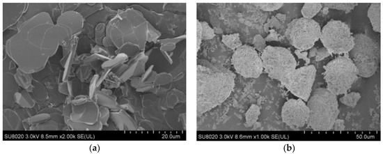
Figure 1.
SEM pictures of BN and MgO powders. (a) SEM picture of BN; (b) SEM picture of MgO.
Figure 2 shows the XRD spectrum of BN and MgO powders. It can be found that there are almost no impurities in powders used in the experiments.
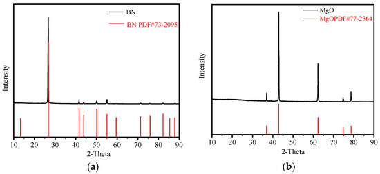
Figure 2.
XRD spectrum of BN and MgO powders. (a) XRD spectrum of BN; (b) XRD spectrum of MgO.
The powder is short-circuited and dried at 200 °C in vacuum with −0.1 Mpa for 48 h before testing to remove the moisture and residual charge inside the powders. Thereafter, the powder is cooled down to the experimental temperature in vacuum to measure the current TDS.
2.2. Measurement System for the Current TDS
A there-electrode system is designed, as shown in Figure 3, for the measurement of current TDS of inorganic insulating powder under different temperatures and different electric fields. The high voltage electrode of the three-electrode system is made into a tank shape, which not only holds the powder specimen, but also the side mechanical pressure. The measurement electrode and the shield electrode are separated by a polytetrafluoroethylene (PTFE) block, and are assembled into a cylindrical plane plate system fixed by bolts, so the external mechanical load is uniformly acted on the powder specimen.
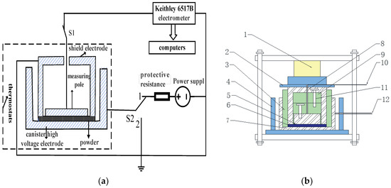
Figure 3.
Measurement and electrode systems for the current TDS. (a) Schematic diagram of the measurement system; (b) Schematic diagram of three-electrode system, where 1—pressure sensor, 2—epoxy resin board, 3—internal insulation, 4—external insulation, 5—measurement electrode with diameter 50 mm, 6—powder specimen, 7—high voltage electrode with inner diameter 94 mm and outer diameter 114 mm, 8—shield electrode with inner diameter 54 mm and outer diameter 74 mm, 9—PTFE block, 10—measurement lead, 11—screws, 12—high voltage lead.
The maximum output voltage of HB-Z103-1AC DC voltage supply is 10 kV with an accuracy of 1 V. A Keithley 6571B electrostatic meter with an accuracy of 10−15 A is used to measure the TDS.
2.3. Measurement Procedure for TDS
The electrode system is put in a temperature-controlled oven for 5 h to ensure that it reaches the testing temperature of 25 °C and 70 °C, respectively. The powder specimen is placed in the three-electrode system and then is applied by 1 MPa pressure. The thickness of powder specimen is controlled in the region of 5~7 mm. The whole electrode system is located in the testing temperature for 1 h, and the temperature of powder specimen is monitored by an infrared temperature gun to ensure it to come into temperature stabilization. The current TDS of powder specimen is then measured via Keithley 6571B electrostatic meter for 1 h under 0.1 and 0.7 kV/mm, respectively.
3. Results and Discussion
3.1. Normal Current TDS
Figure 4a shows the current TDS of BN powder at 25 °C in linear coordinate. It can be seen that the current nearly decreases with time under 0.1 and 0.7 kV/mm, but it cannot be distinguished from each other in the long time even described as in the inset of Figure 4a. So, the TDS of BN powder is shown in double logarithmic coordinate as in Figure 4b.
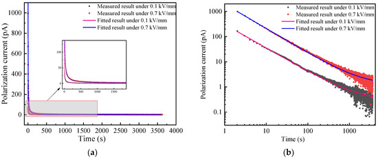
Figure 4.
Current TDS of BN powder at 25 °C. (a) Linear coordinate; (b) double logarithmic coordinate.
It can be seen from Figure 4b that the current TDS changes as a straight line with time at the beginning and gradually tends to the steady state in the double logarithmic coordinate. The relationship between the current and time is consistent with the Curie von Schweidler relation also called “universal law” as shown in Equation (1), which is recognized by many scholars [15] and is used to fit the experimental results in Figure 4b.
In Equation (1), i is the time-domain current, t is the time, At−n is the polarization absorption current, A and n is constant; idc is the steady-state conduction current.
The current TDS of BN powder as shown in Figure 4 is normal, which is fitted by (1) to eliminate the noise signal and achieve the decomposition of the polarization absorption current and the steady-state conduction current. It is yet to be verified whether this denoising process removes only noise rather than any valuable information. Therefore, the conventional residuals of the current TDS are analyzed. The residuals are calculated as:
where is the measured time-domain current and is the fitted current. is the residual value between the measured and fitted current, k is the serial number. The time step is 1 s. The residual values of BN powder under 0.1 and 0.7 kV/mm are calculated as shown in Figure 5a,b, respectively.
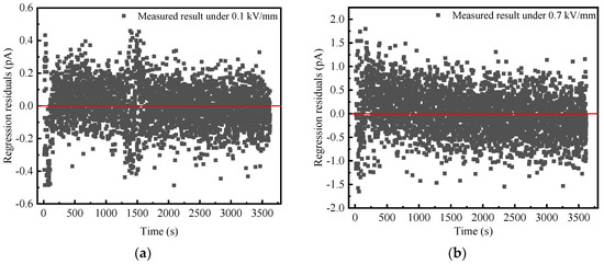
Figure 5.
Residual values of BN powder at 25 °C. (a) 0.1 kV/mm; (b) 0.7 kV/mm.
As can be seen from Figure 5, residual value fluctuates around zero and is independent of time. This result indicates that the current TDS of BN powder i obeys (1), and the removed residual is the white noise. In addition, the residual values under 0.7 kV/mm is significantly higher than that under 0.1 kV/mm, which is mainly attributed to the increase in random fluctuations of the applied DC power supply with the increasing output voltage.
The relaxation polarization current ip(t) and the conduction current idc can be obtained by fitting the measured time-domain current of BN powder with (1). The relaxation polarization P(t) corresponding to ip(t) can be expressed as follows.
The relationship between the relaxation polarization and time is obtained by (3), and then the steady-state relaxation polarization is predicted by the form of a sum of multiple exponential function, as below.
Under 0.1 kV/mm, the steady-state relaxation polarization of BN powder is 1.67 C/m2, and the steady-state susceptibility is 1.89. The conduction current density is 1.36 × 10⁻¹⁴ A/cm2, and the conductivity is 1.36 × 10⁻¹⁵ S/m. Under 0.7 kV/mm, the steady-state relaxation polarization of BN powder is 9.07 C/m2, and the steady-state susceptibility is 1.46. The conduction current density is 5.37 × 10⁻¹⁴ A/cm2, and the conductivity is 7.66 × 10⁻¹⁶ S/m.
3.2. Abnormal Current TDS
The current TDS of MgO at 25 °C is shown in Figure 6. It can be seen that the current under 0.7 kV/mm has a larger offset than that under 0.1 kV/mm, which is attributed to a larger conductive current because the conductive current will increase as the electric field increases [16]. Whether under 0.1 or 0.7 kV/mm, the time-domain current decays to a certain degree with time and then gradually increases with time as shown in the inset of Figure 4. This contradicts with the normal current TDS, and the MgO powder shows an abnormal current TDS. Moreover, when time is larger than 2000 s, the increase rate of time-domain current to time under 0.7 kV/mm is greater than that of 0.1 kV/mm. Namely, the higher electric field leads to a higher increase rate in the long time.
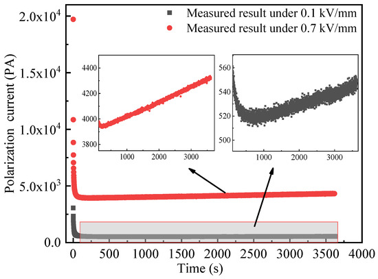
Figure 6.
Current TDS of MgO powder at 25 °C.
The abnormal current TDS is not the first observed in MgO powder, similar abnormal phenomena was found in polymer under DC voltage [17]. The difference is that the former shows abnormal phenomena under low electric field for no more than 1 h, and the latter only shows abnormal current TDS under high electric field for a long time (up to a few days). The abnormal phenomenon of polymer is related to space charge effects, formation, and dissipation of low fraction products in the polymer material. By contrast, due to the low applied electric field and short time, the abnormal time-domain current of inorganic insulating powder is obviously related to the powder’s stability.
The factors that affect the stability of dielectric properties of inorganic insulating powder include the powder’s packing state, the moisture, and the temperature rise. Under a constant applied pressure, the packing state of insulating powder is stable in several seconds or minutes [18]. However, the current TDS of MgO powder shows abnormal phenomena after 200~500 s of the applied voltage as shown in the inset of Figure 6, so the abnormal current spectrum is not attributed to the powder’s packing state.
It is found that the surface modification of inorganic insulating powder is able to greatly inhibit the moisture absorption [19,20,21,22]. A typical silane coupling agent of KH550 is used to modify the surface of MgO powder and to verify whether the abnormal current TDS is related to the moisture absorption during the experiment.
Figure 7 shows the current TDS of the modified MgO powder at 25 °C. It can be seen from Figure 7a that under 0.1 or 0.7 kV/mm, the time-domain current of the modified MgO powder decreases monotonically with time and tends to be the steady state. The insets of Figure 7a also show that the time-domain current of MgO in the long time is nearly closed to the steady state for 0.1 and 0.7 kV/mm. These means that normal current TDS occurs in modified MgO powder and no abnormal phenomena appears.
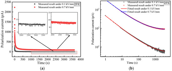
Figure 7.
Current TDS of surface modified MgO powder at 25 °C. (a) Linear coordinate; (b) double logarithmic coordinate.
Moreover, the Fourier transform infrared spectrometer (FTIR) of three powders of MgO, BN, and surface modified MgO before and one hour after the current TDS measurement are shown in Figure 8a–c, respectively.
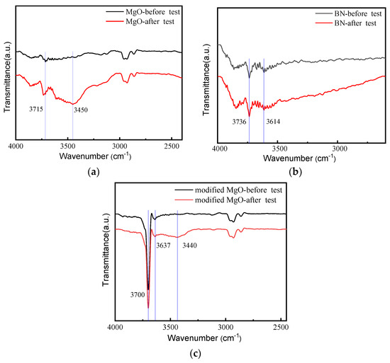
Figure 8.
FTIR of powders before and after TDS measurement. (a) MgO powders; (b) BN powders; (c) modified MgO powders.
The infrared absorption peaks at around 3700 cm−1, 3400 cm−1 correspond to the antisymmetric stretching vibration peak and symmetric stretching vibration peak of the O-H bond in water molecule. From Figure 8a, it can be seen that the intensity of the anti-symmetric stretching vibration peak of the O-H bond of the MgO powder at 3715 cm−1 increased significantly after the experiment, and the symmetric stretching vibration peak of the O-H bond of the water molecule appeared at 3450 cm−1, indicating that the moisture content in MgO powder increased significantly after the experiment, and the powder was damped during the experiment. Figure 8b shows that the absorption peak intensity of O-H bond at wavelength 3736 cm−1 and 3614 cm−1 of the BN powder before and after the experiment is basically the same, which means that the BN powder is not significantly damped during the experiment. As can be seen from Figure 8c, the absorption peak intensity of O-H bond at wavelength 3700 cm−1 and 3637 cm−1 of the modified MgO powder after the experiment is basically the same, but a small O-H bond appears at 3440 cm−1, indicating that the modified MgO powder is slightly damped during the experiment, but it is not as serious as the unmodified MgO damped.
Combined with the current TDS of these powders, it can be found that the abnormal TDS is mainly caused by the absorption of moisture in powders.
Curie von Schweidler formula (1) is used to fit the measured current TDS of modified MgO powder, as shown in Figure 7b. It can be observed that the fitting effect of modified MgO powder is similar to that of BN powder, which also indicates that the current TDS of the modified MgO powder is normal. The comparison of current TDS between the original MgO powder in Figure 7 and the modified MgO powder in Figure 7a shows that the time-domain current of the modified MgO powder is much less than that of the original one. This suggests that the surface modification can eliminate the effect of the powder’s moisture absorption on the measurement of current TDS.
From the above, it can be concluded that the powder’s moisture absorption contributes a lot to the abnormal time-domain current. To further verify whether the temperature rise caused by the Joule heat of powder also has an effect on the measurement, the current TDS of the modified MgO powder at 70 °C is measured as shown in Figure 9.
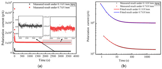
Figure 9.
Current TDS of surface modified MgO powder at 70 °C. (a) Linear coordinate; (b) double logarithmic coordinate.
From Figure 9a, it is found that the time-domain current of the modified MgO at 70 °C decreases with time and tends to be in the steady state in the long time under 0.1 and 0.7 kV/mm, respectively. This indicates that the current TDS of the modified MgO powder at 70 °C is still normal.
Comparing Figure 7 with Figure 9, it can be learnt that the time-domain current of modified MgO powder at 70 °C is much higher than that of 25 °C, which means that more Joule heat is generated at 70 °C. The more Joule heat only contributes to a larger conduction current (i.e., a larger steady-state time-domain current), but the conduction current hardly increases with time, and the current TDS is normal. Thus, the Joule heat can be ruled out to affect the measured abnormal TDS.
3.3. Analysis of Abnormal Current TDS
According to the above analysis, the reason for the abnormal current TDS is the MgO powder’s moisture absorption, which occurs during the measurement process and is uncontrollable. The similar phenomena and relative conductive mechanism are also described in reference [23]. Therefore, it is of great significance to eliminate the deviation from normal TDS caused by influence of the moisture absorption and to obtain the real dielectric parameters of inorganic insulating powder.
In order to eliminate the deviation, the polynomial expansion of time is added in (1) to describe the time-varying trend because of the generality of polynomial in mathematics. So, there is no physical mechanism involved. It should be noted that this approach is a kind of trend filtering method for current TDS in this sense, and (1) is rewritten as below.
where km is a coefficient, and l is the number of time term. The abnormal current TDS is fitted by the least squares method with (4), and the fitting curve can be obtained under different values of l. The value of l is determined by the optimal fitting effect. Subsequently, the current TDS without time-varying factors and the white noise are obtained, respectively.
With this method, the time-domain current spectrum of original MgO powder under 0.1 kV/mm as an example is fitted to illustrate the feasibility. When fitting with Equation (4), it is found that when , the fitting does not converge. While l ≤ 3, the fitting parameters are shown in Table 1.

Table 1.
Fitting parameters of different formulars.
Comparing the fitting effect of l ≤ 3, it can be seen that when the value of l is 3, the fitting effect is the best. The relationship between the fitting residual and time for l = 3 is shown in Figure 10.
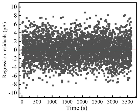
Figure 10.
Relationship between residual values of original MgO powder and time obtained by (4) with l = 3 at 25 °C.
Figure 10 shows that the residual values belong to white noise. The normal time-domain current spectrum of the inorganic insulating powder with moisture absorption is obtained by eliminating the effects of white noise and time-varying factors. For the original MgO powder under 0.1 kV/mm at 25 °C, the fitting parameters of A = 2567.856, n = 0.885, and idc = 184.877 pA are obtained via (4) by eliminating the effect of time-varying factors. Accordingly, the steady-state relaxation polarization of the original MgO powder under 0.1 kV/mm is 18.576 C/m2, and the steady-state susceptibility is 20.99. The conductivity is 8.7 × 10⁻¹³ S/m.
4. Conclusions
Insulation properties of inorganic insulating powder is extremely sensitive to the moisture. In the absence of absolutely sealed experimental conditions, during the measurement of insulation properties of hydrophilic inorganic insulating powder, such as MgO powder, the moisture exchange between the tested specimen and the external atmosphere environment is easy to occur and makes the tested specimen become a time-varying system, resulting in an abnormal time-domain current spectrum. When the testing temperature is low, the powder tends to absorb moisture from the external atmosphere, which increases the micro-water content of the insulating powder and in turn forms a time-varying conduction current. Thus, the time-varying conduction current leads to the abnormal time-domain current spectrum in the end of time.
The hydrophobic inorganic insulating powder, such as BN powder, is insensitive to moisture, and its measured specimen is able to be regarded as a time-invariant system during the whole measurement, so the time-domain current decreases with time and approaches to the steady state, and the time-domain current spectrum is normal.
For the measured powder, its initial moisture state is known or controllable, but its moisture absorption during the measurement is uncontrollable. In this sense, the effect of the powder’s moisture absorption occurred during the measurement must be eliminated in order to obtain the real dielectric properties of inorganic insulating powder. An absolutely sealed condition can avoid the moisture exchange between the powder specimen and the external atmosphere during the measurement. By contrast, when the absolutely sealed condition cannot be achieved, the time-varying term is added to the least squares fitting equation to eliminate the influence of time-varying factors. In this paper, a polynomial term of time is used in Curie von Schweidler formula, which depends on the time-varying characteristics of the time-domain current spectrum in the end of time.
The reconstructed normal time-domain current spectrum is obtained by excluding the added term of time, and the dielectric parameters (e.g., conductivity and steady-state susceptibility) of inorganic insulating powder can be calculated, which lays an important foundation for the application of inorganic insulating powder in the electrical equipment.
Author Contributions
Conceptualization, Z.L.; data collection, Y.X.; funding acquisition, Z.L.; investigation, Y.X. and Y.H.; methodology, Y.S.; supervision, Z.L.; writing—original draft, Y.X.; writing—review and editing, W.G. All authors have read and agreed to the published version of the manuscript.
Funding
This research was funded by National Natural Science Foundation of China, No. 51837003.
Data Availability Statement
Not applicable.
Conflicts of Interest
The authors declare no conflict of interest.
References
- Chen, Y.H.; Wang, Y.S.; Zhao, D.E.; Wang, H.; He, X.M.; Zheng, Q.J.; Lin, D.M. Enhanced energy storage properties and dielectric stabilities in BNT-based ceramics via multiphase and dielectric peak broadening engineering. Mater. Chem. Phys. 2022, 290, 126542. [Google Scholar] [CrossRef]
- Zhou, H.F.; Tan, X.H.; Liu, X.B.; Wang, K.G.; Li, S.X.; Chen, X.L. Low permittivity MgO-xB(2)O(3)-yBaCu(B2O5) microwave dielectric ceramics for low temperature co-fired. Ceram. Technol. 2018, 29, 18486–18492. [Google Scholar]
- Kulawik, J.; Szwagierczak, D.; Groger, B. Investigations of properties of ceramic materials with perovskite structure in chosen electronic applications. Bull. Pol. Acad. Sci.-Tech. 2007, 55, 293–297. [Google Scholar]
- Zhou, Y.; Hu, J.; Chen, X.; Yu, F.; He, J.L. Thermoplastic polypropylene/aluminum nitride nanocomposites with enhanced thermal conductivity and low dielectric loss. IEEE Trans. Dielectr. Electr. Insul. 2016, 23, 2768–2776. [Google Scholar] [CrossRef]
- Wang, Y.Y.; Wang, C.; Zhang, Z.X.; Xiao, K. Anti-thermal aging properties of low-density polyethylene-based nanocomposites. IEEE Trans. Dielectr. Electr. Insul. 2018, 25, 1003–1013. [Google Scholar] [CrossRef]
- Zhang, X.X.; Wen, H.; Chen, X.Y.; Wu, Y.J.; Xiao, S. Study on the thermal and dielectric properties of SrTiO3/epoxy nanocomposites. Energies 2017, 10, 692. [Google Scholar] [CrossRef]
- Vishal, M.; Kumar, A.P. Dynamic mechanical analysis of PVC/TiO2 nanocomposites. Adv. Compos. Hybrid Mater. 2018, 1, 741–747. [Google Scholar]
- Pilarska, A.A.; Klapiszewski, L.; Jesionowski, T. Recent development in the synthesis, modification and application of Mg(OH)(2) and MgO: A review. Powder Technol. 2017, 319, 373–407. [Google Scholar] [CrossRef]
- Harvey, A.; Walker, S.A. Mineral-insulated magnets for high-radiation environments. IEEE Trans. Nucl. Sci. 1969, 16, 611–612. [Google Scholar] [CrossRef]
- Suo, C.Y.; Li, Z.H.; Sun, Y.L.; Han, Y.S. Application of L1 trend filtering technology on the current time domain spectroscopy of dielectrics. Electronics 2019, 8, 1046. [Google Scholar] [CrossRef]
- Wang, S.H.; Li, J.Y.; Li, S.T. XLPE/h-BN nanocomposites with enhanced DC insulation properties. IEEE Trans. Dielectr. Electr. Insul. 2022, 29, 62–68. [Google Scholar] [CrossRef]
- Yu, C.P.; Zhang, J.; Tian, W.; Fan, X.D.; Yao, Y.G. Polymer composites based on hexagonal boron nitride and their application in thermally conductive composites. RSC Adv. 2018, 39, 21948–21967. [Google Scholar] [CrossRef] [PubMed]
- Pakdel, A.; Zhi, C.; Bando, Y.; Golberg, D. Low-dimensional boron nitride nanomaterials. Mater. Today 2012, 15, 256–265. [Google Scholar] [CrossRef]
- Duan, G.Y.; Wang, Y.; Yu, J.R.; Zhu, J.; Hu, Z.M. Novel poly(m-phenyleneisophthalamide) dielectric composites with enhanced thermal conductivity and breakdown strength utilizing functionalized boron nitride nanosheets. Macromol. Mater. Eng. 2019, 304, 1900310. [Google Scholar] [CrossRef]
- Jonscher, A.K. Dielectric Relaxation in Solids; Chelsea Dielectrics Press: London, UK, 1983. [Google Scholar]
- Sun, Y.L.; Li, Z.H.; Han, Y.S.; Zhang, X. Quantitative investigation of the nonlinear polarization in epoxy/SiC nanocomposite. IEEE Trans. Dielectr. Electr. Insul. 2021, 28, 66–73. [Google Scholar] [CrossRef]
- Hossein, G.; Thomas, C.; Martin, C.; Emmanuel, L.; Hossein, G.; Lorenz, H.; Henrik, H.; Linnea, P.; Julia, V. Long-term conductivity decrease of polyethylene and polypropylene insulation materials. IEEE Trans. Dielectr. Electr. Insul. 2017, 24, 1485–1493. [Google Scholar]
- Li, H.; Sego, D.C. Equation for complete compaction curve of fine-grained soils and its applications. In Proceedings of the Symposium on Constructing and Controlling Compaction of Earth Fills, Seattle, WA, USA, 1–2 July 1999. [Google Scholar]
- Zhang, Y.; Fang, F.; Wang, C.; Wang, L.D.; Wang, X.J.; Chu, X.Y.; Li, J.H.; Fang, X.; Wei, Z.P.; Wang, X.H. Hydrophobic modification of ZnO nanostructures surface using silane coupling agent. Polym. Compos. 2014, 35, 1204–1211. [Google Scholar] [CrossRef]
- Fei, X.N.; Xi, X.Z.; Gao, J.; Zhu, S.; Jiao, X.M.; Cao, L.Y.; Liu, L.J. Effects of silica fume powder modified by oleic acid on the settleability of bulking sludge. Environ. Technol. 2022, 11–16. [Google Scholar] [CrossRef]
- Pallon, L.K.H.; Hoang, A.T.; Pourrahimi, A.M.; Hedenqvist, M.S.; Nilsson, F.; Gubanski, S.; Gedde, U.W.; Otsson, R.T. The impact of MgO nanoparticle interface in ultra-insulating polyethylene nanocomposites for high voltage DC cables. J. Mater. Chem. A 2016, 4, 8590–8601. [Google Scholar] [CrossRef]
- Arase, H.; Taniguchi, K.; Kai, T.; Murakami, K.; Adachi, Y.; Ooyama, Y.; Kunugi, Y.; Ohshita, J. Hydrophobic modification of SiO2 surface by aminosilane derivatives. Compos. Interface 2018, 26, 15–25. [Google Scholar] [CrossRef]
- Uchikawa, F.; Shimamoto, K.; Hasegawa, T.; Yoshida, T. Conduction mechanisms and time dependence of sensing characteristics on SiO2 humidity-sensitive films. Hyomen Kagaku 1984, 5, 233–240. [Google Scholar] [CrossRef]
Publisher’s Note: MDPI stays neutral with regard to jurisdictional claims in published maps and institutional affiliations. |
© 2022 by the authors. Licensee MDPI, Basel, Switzerland. This article is an open access article distributed under the terms and conditions of the Creative Commons Attribution (CC BY) license (https://creativecommons.org/licenses/by/4.0/).