Next Article in Journal
Geochemical Characteristics of Water Produced from Coalbed Methane Wells in the Southern Qinshui Basin and Construction of an Associated Model: Implications for Coalbed Methane Co-Production
Next Article in Special Issue
Degradation of Concrete Structures in Nuclear Power Plants: A Review of the Major Causes and Possible Preventive Measures
Previous Article in Journal
Thermoelectric Generator for Waste Energy Recovery in Transport
Previous Article in Special Issue
Analysis of a Hybrid Nuclear Renewable Energy Resource in a Distributed Energy System for a Rural Area in Nigeria
 
 
Correction published on 10 May 2024, see Energies 2024, 17(10), 2293.
Article

Chromium-Coated Zirconium Cladding Neutronics Impact for APR-1400 Reactor Core

by
Mohammad Alrwashdeh
* and
Saeed A. Alameri
*
Department of Nuclear Engineering, Emirates Nuclear Technology Center (ENTC), Khalifa University of Science and Technology, Abu Dhabi P.O. Box 127788, United Arab Emirates
*
Authors to whom correspondence should be addressed.
Energies 2022, 15(21), 8008; https://doi.org/10.3390/en15218008
Submission received: 29 September 2022 / Revised: 25 October 2022 / Accepted: 26 October 2022 / Published: 28 October 2022 / Corrected: 10 May 2024
(This article belongs to the Special Issue New Challenges in Nuclear Energy Systems)

Abstract

:
The accident-tolerant fuel concept involves replacing the conventional cladding system (zirconium) with a new material or coating that has specific thermomechanical properties. The aim of this study is to evaluate the neutronics performance of a chromium coating concept and design solutions. A Zircaloy–uranium fuel system (Zr–U) is currently used as a standard fuel system in pressurized water reactors around the world. This investigation presents the benefits of utilizing an alternative cladding material such as chromium coating and the effects on the thermal neutron parameters of the way in which the chromium coating is introduced in the reactor fuel. Among these significant benefits is an increase in the reactor fuel’s thermal conductivity, which improves reactor safety. Two types of fuel-cladding systems were investigated: Zircaloy–uranium (Zr–U) and Zircaloy–chromium (Zr–Cr–U) coating fuel systems. Neutronics analysis evaluations were performed for the selected fuel assemblies and a two-dimensional full core based on an APR-1400 reactor design. Neutronics analyses were performed for the application of the new fuel-cladding material systems using the reactor-physics Monte Carlo code Serpent 2.31.

1. Introduction

In conventional light-water-reactors (LWRs), zirconium alloy has been historically used as a fabricated fuel system. There is a demand for higher fuel-burnup levels for LWR core designs, which requires cladding materials with higher corrosion resistance [1]. Notably, there is a worldwide demand for LWR fuel with higher burnup levels, reduced material corrosion, and improved cladding material creep properties, leading the nuclear fuel industry to develop alternative cladding systems to conventional zircaloy (Zr), which has mostly been replaced with proprietary Zr-based cladding alloys [2].
Westinghouse and the University of Wisconsin are developing and testing a chromium-cladding fuel system that consists of ZIRLO® and Optimized ZIRLO™ cladding using a cold spray-coating process to apply the chromium coating [3,4]. The proposed chromium coating thickness is up to 30 µm based on the experimental testing that Westinghouse performed on the chromium-cladding coating system. The assessments done by Kim et al. [5] included corrosion tests in high-temperature steam and pressurized water, mechanical property testing, and chalk river unidentified deposit (CRUD) and loss of coolant accident (LOCA) post-quench ductility tests [5].
Metallic coatings of chromium for accident-tolerant fuel (ATF) have been proposed as one of the potential options for ATF cladding [6]. Such coatings could be used to enhance the safety and reliability of light-water reactors (LWRs) that are currently being developed by join research between University of Wisconsin–Madison and Westinghouse Electric Company [7]. After the Great East Japan Earthquake, the Fukushima Daiichi Nuclear Power Plant had to endure a tsunami, and the subsequent events that followed led to global interest in enhancing and developing new forms of reactor fuel or utilizing different cladding materials to expand the reactor safety margin during extreme operation conditions [8]. In response, many institutes have launched research and development programs on ATF materials [9]. To this end, new ATF cladding concepts are expected to be formulated to overcome the severe consequences in various operational conditions (normal and abnormal) [10]. After deformations such as thermal expansion, ballooning, or irradiation growth of the cladding tube under normal operating settings or accident conditions, including quenching of overheated fuel rods, no coating spallation was discovered on the Cr-coated Zr alloys [11].
ATF fuel-cladding systems are being improved primarily to overcome high-temperature oxidation that may occur as a result of a design basis accident (DBA) or operation beyond the reactor fuel’s standard design basis. To do so, a set of general requirements must be adapted for the reactor fuel and cladding design. The requirements may include the retention of the cladding shape, retention of all pellets and fission products, and effective transfer of heat to the coolant [12].
Based on the experimental results obtained by Schuster and his team in CEA-France [13], for high-steam temperatures, chromium still has a high resistance to oxidation. Therefore, adding chromium as a cladding coating lead to enhanced mechanical properties for the cladding system compared with conventional Zr cladding. Therefore, adopting a chromium coating enhances and expands the capacity to overcome severe accidents, such as loss-of-coolant accidents (LOCA). Generally, most ATF cladding materials are smart materials developed for improved oxidation under extreme operating conditions, such as a sudden increase of the system temperature beyond the operation level [14].
The focus of this research is the neutronics evaluation and comparisons between Zircaloy and chromium-coated fuel-cladding systems, this evaluation were carried out for various fuel assemblies and two-dimensional APR-1400 core. previous research calculations have been performed for different fuel-cladding material systems [15,16,17] and two-dimensional reactor cores. The neutronic performances of potential APR-1400 ATF cladding systems, such as the multiplication factor, neutron spectrum, linear power, and radial neutron flux, were calculated and compared with the reference cladding, specifically the neutronic penalty of adapting a new fuel-cladding system in the APR-1400 reactor core towards the end of the cycle (EOC). In this study specified Cr coating thicknesses (10 µm, 15 µm, and 20 µm) are selected to assure the accident-tolerance and high-temperature corrosion resistance of Zr alloy cladding throughout a fuel life cycle.

2. Design Parameters

2.1. Core Description

The reactor fuel assemblies contain 236 fuel rods, four guide tubes, neutron burnable absorber rods, and one instrument tube layout in a 16 × 16 square array, which is held together by a bottom and top nozzle and guide tubes welded to 12 spacer grids [17]. The reactor core contains 93 control assemblies, 241 fuel assemblies with varied enrichment, and 61 instrument assemblies [18]. The active fuel is 3.810 m in height with a diameter of 3.647 m [19]. Table 1 presents the design parameters for the APR-1400 reactor core.

2.2. Materials

Although chromium has numerous advantages over other ATF materials, the high thermal-neutron absorption cross section may negatively impact the fuel cycle length. Therefore, chromium coating was adapted with a specific thickness (10 µm, 15 µm, and 20 µm) due to its corrosion resistance and its ability to reduce the production of hydrogen gas. Table 2 shows the chemical composition, density, and absorption cross section of each cladding material.

2.3. Core Configuration

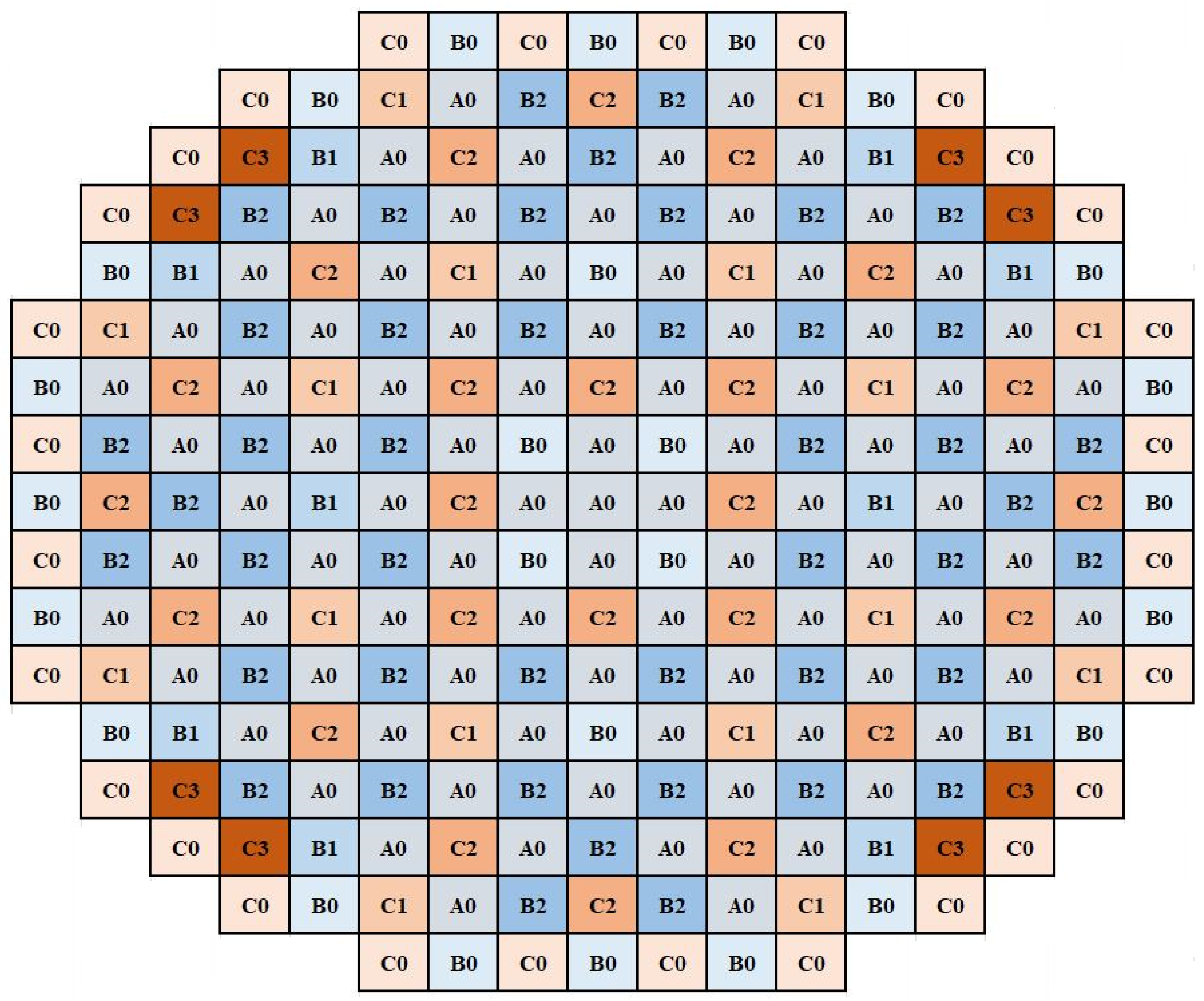
The APR-1400 reactor core is composed of eight types 16 × 16 square fuel assemblies. Three of them have no gadolinium and are labeled as a0, b0, and c0. Other assemblies have various numbers of Gd2O3 rods and are labeled as b1, b2, c1, c2, and c3. Table 3 presents the specifications of each fuel assembly, and Figure 1 shows the layout of various types of APR-1400 assemblies in cross-sectional views. Figure 2 presents APR-1400 reactor-core fuel-loading pattern.

2.4. Fuel Assembly and Core Models

The Monte Carlo method was utilized in Serpent 2.31 code to perform reactor-physics and burnup calculations [21,22]. The generation of thermal-neutron homogenized group constants was utilized to carry out two-dimensional full core neutronics calculations. For ATF materials, fuel geometry modification may be applied to the fuel rods to overcome high absorption for thermal neutrons for a newly adapted material. The evaluated neutronics parameters for reactor fuel assemblies and a two-dimensional full core were evaluated using nuclear data library ENDF/B-VII.1 [23] and enhanced nuclear data libraries [24,25,26,27]. Based on these considerations, the total cycles were set to 250 while skipping 50 cycles with particles per cycle set to 10,000 for fuel unit cells, 100,000 for various fuel assemblies, and 500,000 neutrons for full core.

3. Results

3.1. Various Enrichment Unit Cell Models

To investigate the role of chromium coating on the assembly neutronics, Serpent 2.31 code was used to model the APR-1400 pin-cell design. The fuel enrichment of each pin cell is 1.68, 2.64, 3.14, and 3.46%, and the helium gap is placed between the fuel pellet and the cladding layer with a density of 0.0015599 g/cm3. The outer fuel pellet’s radius was 4.095 mm, its helium gap was 85.0 μm, and the cladding thickness was 570.0 μm. Water was utilized as a coolant and a moderator.
As a reference case, a pin cell with Zircaloy clad was used. The burnup calculations were performed using a constant power density of 40 kW/kgU for a discharge burnup value of 20 GWd/ton, which is around 500 to 600 effective full-power days (EFPD). Table 4 provides a summary of the geometry of the pin cell for the reference and chromium-coating cases.
Table 5 presents the infinite multiplication factor (kinf) values for different pin-cell enrichments for both types of cladding materials. The computation of the fuel pin models was evaluated using the likelihood of collision methods. The modeled system temperatures are as follows: 900 K for the fuel, 600 K for the cladding, and about 580 K for the moderator.
Figure 3 demonstrates the variation in kinf between the reference case (Zr) and chromium coating with thicknesses of 10 µm, 15 µm, and 20 µm, with various fuel unit cell enrichment (1.68 wt %, 2.64 wt %, 3.14 wt %, and 3.46 wt %). Compared with the reference case, the additional chromium coatings with different thicknesses have a slight impact on kinf at the beginning of life (BOL). As seen in Table 5 and Figure 3, the thickness of chromium cladding has a direct impact on the initial value of the multiplication factor. From Table 5 and Figure 3, the reactivity differences at the BOL for the fuel unit cell with a coating thickness of 10 µm are −317.0 pcm, −246.0 pcm, −257.0 pcm, and −214.0 pm for 1.68 wt %, 2.64 wt %, 3.14 wt %, and 3.46 wt % fuel unit cell enrichments, respectively. As the coating thickness increases, the reactivity penalty also increases due to the reduction of the thermal neutron population inside the modeled unit cell. For that, the coating thickness with less impact on the neutronics parameters such as kinf during the fuel life cycle is more favorable to adopt in future fuel design. Table 5 presents the reactivity penalty associated with different thicknesses of chromium coating.
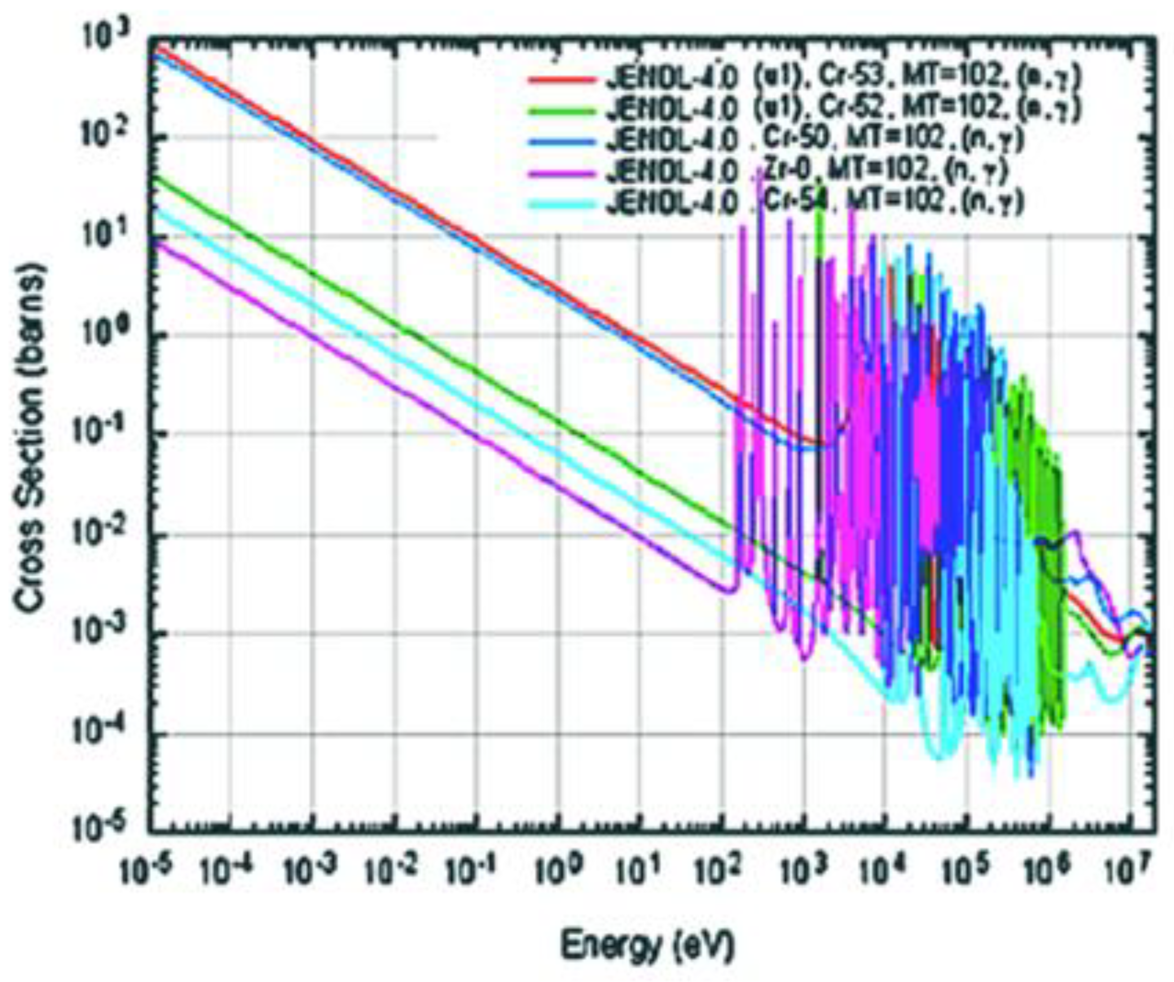
Nuclei such as 90Zr40 have a “magic number” of neutrons that leads to the tendency to capture a low number of thermal neutrons. Figure 4 shows the thermal-neutron capture cross sections for both fuel-cladding systems (Zr–U, and Zr–Cr–U). In the thermal energy region (1/v region), the capture cross section of the reference Zircaloy is on the order of 103 barns less than those of Cr-50 and Cr-53 and around 101 and 102 barns for Cr-54 and Cr-52, respectively. However, due to the thin coating layers of chromium (10 µm, 15 µm, and 20 µm), the neutronics penalty regarding the reference Zircaloy is acceptable, as presented in Table 5.
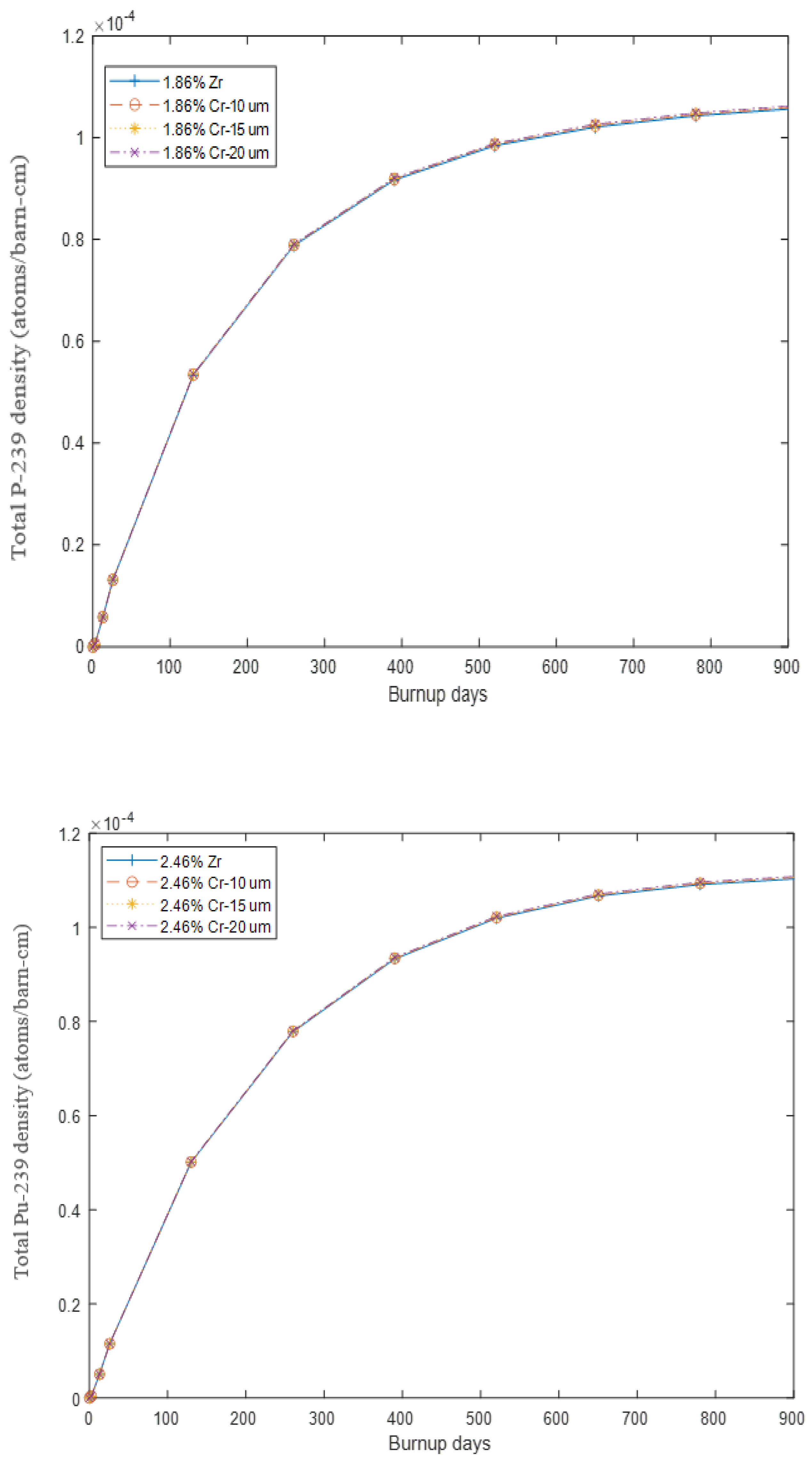
Figure 5 shows the evolution of the 239Pu content during the fuel life cycle for both the Zircaloy and chromium-coating cladding systems. The 1.68 wt %, and 2.64 wt % fuel unit cell enrichments were selected to demonstrate 239Pu production through the fuel life cycle. Since 239Pu is a fissionable material, it has an impact on the thermal neutron population within the modeled system, which leads to more excess reactivity during the fuel life cycle. The chromium coating thickness (10 µm, 15 µm, and 20 µm) does not have a major impact on the evolution of 239Pu for the modeled fuel unit cells (the 1.68 wt %, and 2.64 wt %). As expected, despite the higher thermal-neutron cross section for chromium, the generation of 239Pu is almost the same as that with the reference Zircaloy-fuel-cladding system. In general, with a higher number of fast neutrons within the modeled fuel system, there is a higher probability of 238U nuclides transmuting to 239Pu nuclides. In the fuel unit cell models (1.68 wt %, and 2.64 wt %) the thin layer of the chromium coating does not have a major effect on the thermal neutron population. Consequently, the 239Pu production rates during the fuel life cycle are almost the same for all the modeled thicknesses with various fuel unit cell enrichments.

3.2. Reactor Assemblies Model Calculations

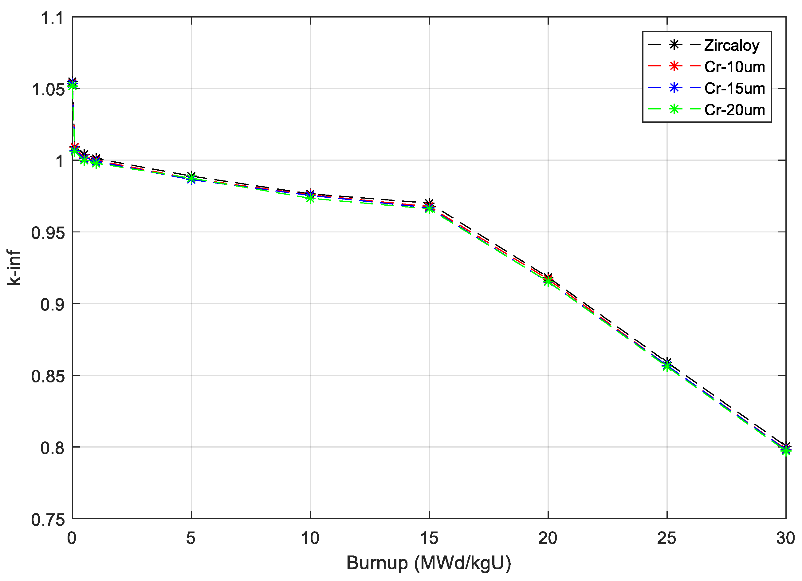
The fuel assemblies were designed, developed, and organized in a specific way to optimize the neutronic performance in terms of energy and space distribution. The neutronics parameters calculations were carried out to assure criticality during the desired length of the fuel life cycle, for example, the neutron multiplication factor, thermal flux spectrum, and linear power distribution. Furthermore, in this study, at an assembly level, burnup calculations were carried out to measure the changes due to applying chromium coating with various thicknesses (10 µm, 15 µm, and 20 µm) over the APR-1400 reactor lifetime. Burnup calculations were carried out on several types of APR-1400 reactor fuel assemblies, and kinf values for both Zircaloy-uranium (Zr–U) and Zircaloy-chromium (Zr–Cr–U) cladding systems were evaluated and compared. Figure 6 illustrates selected fuel assemblies (c3 and b1) that maintained the same trend as a function of burnup toward the end of the cycle. As expected, the kinf values in the BOC for both cladding systems (Zr–U and Zr–Cr–U) are practically identical.
For the c3 fuel assembly, the kinf values are around 1.10449 ± 0.0005, 1.10263 ± 0.0005, 1.10116 ± 0.0006, and 1.10040 ± 0.0006 for Zircaloy, Zr–Cr–U-10 µm, Zr–Cr–U-15 µm, and Zr–Cr–U-20 µm, respectively. The reactivity differences between the reference and coated cladding system material are about −167.0, −302.0, and −372.0 PCM for Zr–Cr–U-10 µm, Zr–Cr–U-15 µm, and Zr–Cr–U-20 µm, respectively, while for b1 assembly these values are around 1.05485 ± 0.0006 (Zr), 1.05369 ± 0.0006 (10 µm), 1.05332 ± 0.0006 (15 µm), and 1.05169 ± 0.0006 (20 µm), and the reactivity difference compared with the original fuel-cladding system is about −110.0, −145.0, and −300.0 PMC for Zr–Cr–U-10 µm, Zr–Cr–U-15 µm, and Zr–Cr–U-20 µm, respectively.
Table 6 shows the differences in kinf and reactivity at BOC for various APR-1400 fuel assemblies. As shown in Figure 6, because of the high absorption cross section and low thickness of the Cr coating, the values of kinf are not significantly affected during the fuel life cycle compared with that of the reference Zr–U fuel-cladding system. There is an obvious effect of the high absorption of thermal neutrons associated with fuel assemblies containing gadolinium rods, as presented in Figure 6. As expected, the high absorption cross section of gadolinium suppresses the initial reactivity during the fuel life cycle. regardless of the different thicknesses of the chromium cladding coating (10 µm, 15 µm, and 20 µm) and the high absorption cross section of thermal neutrons in Cr isotopes. Similar tendencies were observed for the various thicknesses of Cr coating. This leads to almost constant reactivity differences between the three types of cladding coating toward the end of the cycle. On the other hand, APR-1400 fuel assemblies with a 10 µm chromium thickness have an almost similar manner to the reference fuel-cladding system, with less reactivity penalty at BOC compared with the other chromium coating thicknesses (15 µm, and 20 µm) as presented in Table 6. For a0 fuel assembly type, the reactivity difference between 10 µm and 15 µm is about 202.0 pcm, and between 10 µm and 20 µm is about 382.0 pcm, and so on for other types of APR-1400 fuel assemblies, which makes the 10 µm, chromium coating thickness more adaptable in the APR-1400 fuel assemblies design.
Figure 7 presents the neutron spectrum for selected APR-1400 fuel assemblies for both Zr–U and Zr–Cr–U cladding systems at BOC. As presented in the figure, the thermal reactor neutron spectrum is divided into three regions: thermal, epithermal (slowing down (1/E)), and fast regions. Because of the elastic scattering and the moderator, these neutrons were slowed down toward the 1/E and thermal energy ranges, resulting in the flux spectrum shown in Figure 7 for the b1 fuel assembly.
The thermal neutron flux energy peak depends on the fuel material composition, moderator temperature, and materials. The effect of adding chromium coating with different thicknesses to the Zircaloy cladding on the thermal neutron spectrum hardening was investigated and compared to the behavior of the original cladding system of the APR-1400 fuel assemblies.
Despite the large thermal-neutron absorption cross section, both the reference cladding (Zr–U) and coated cladding (Zr–Cr–U) with different thicknesses presented the same behavior in the thermal energy range. This behavior is unexpected for a coated-cladding system with a large absorption cross section and occurred because of the low thickness (in the range of µm) compared to the cladding material.
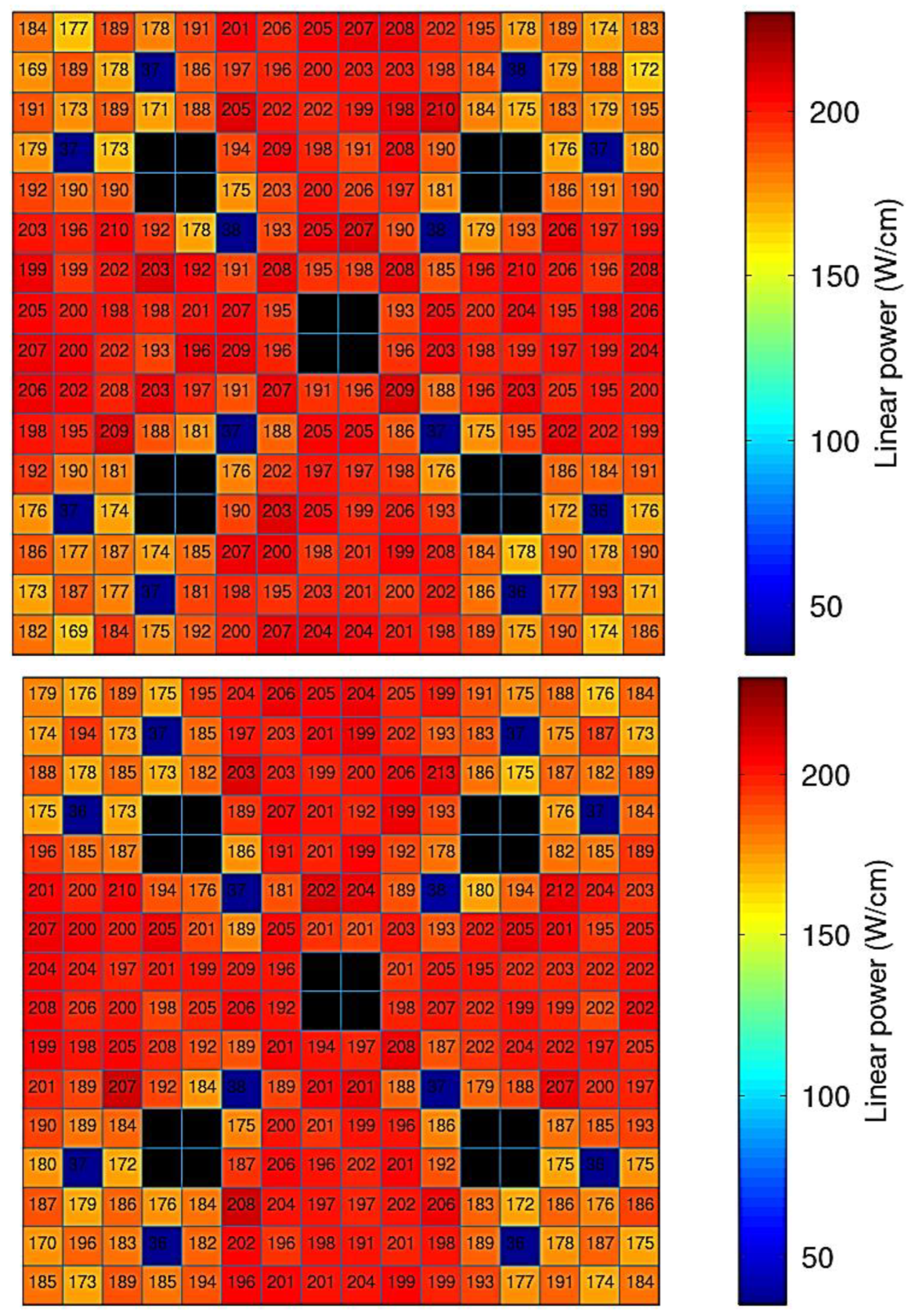
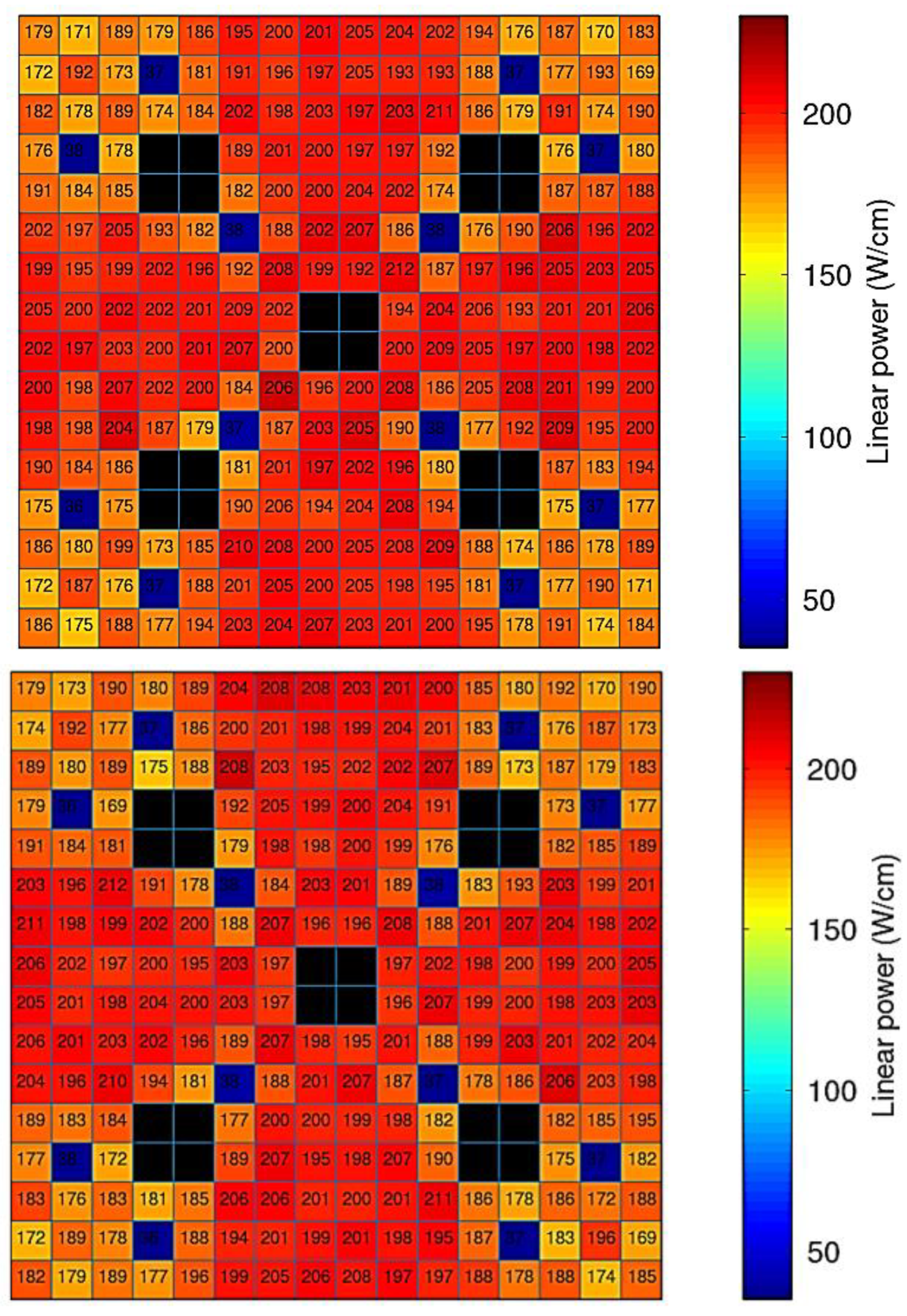
Figure 8 shows the fuel assembly’s linear power distribution for the reference cladding and coated cladding with different thicknesses. The power distribution across the reactor assembly can be used to predict the heat flux and the fuel’s centerline temperature distribution to enhance the safety calculations for an operating power plant.
The analyses of pin power distribution were obtained by evaluating the reaction rate and density distribution across the fuel assembly for thermal neutrons using the Serpent 2.31 code. As expected, the linear pin power across the radial positions for the reference cladding and coated cladding for the b1 fuel assembly is symmetric with maximum values of 210.0, 213.0, 212.0, and 211.00 W/cm for Zr–U, Zr–Cr–U-10 µm, Zr–Cr–U-15 µm, and Zr–Cr–U-20 µm, respectively.
The gadolinia fuel pin positions are presented in dark blue, and the average values of the linear power in these positions for all cases are about 37.0 W/cm. The sudden drop in the linear power in these positions is due to the absorption of the thermal neutron within the gadolinium rods. The linear power in the water positions is equal to zero because of the absence of fission materials in these locations. As expected, the fuel pins surrounding the water positions showed higher pin power than the rest of the fuel pins due to the thermalization process for thermal neutrons in the water region.
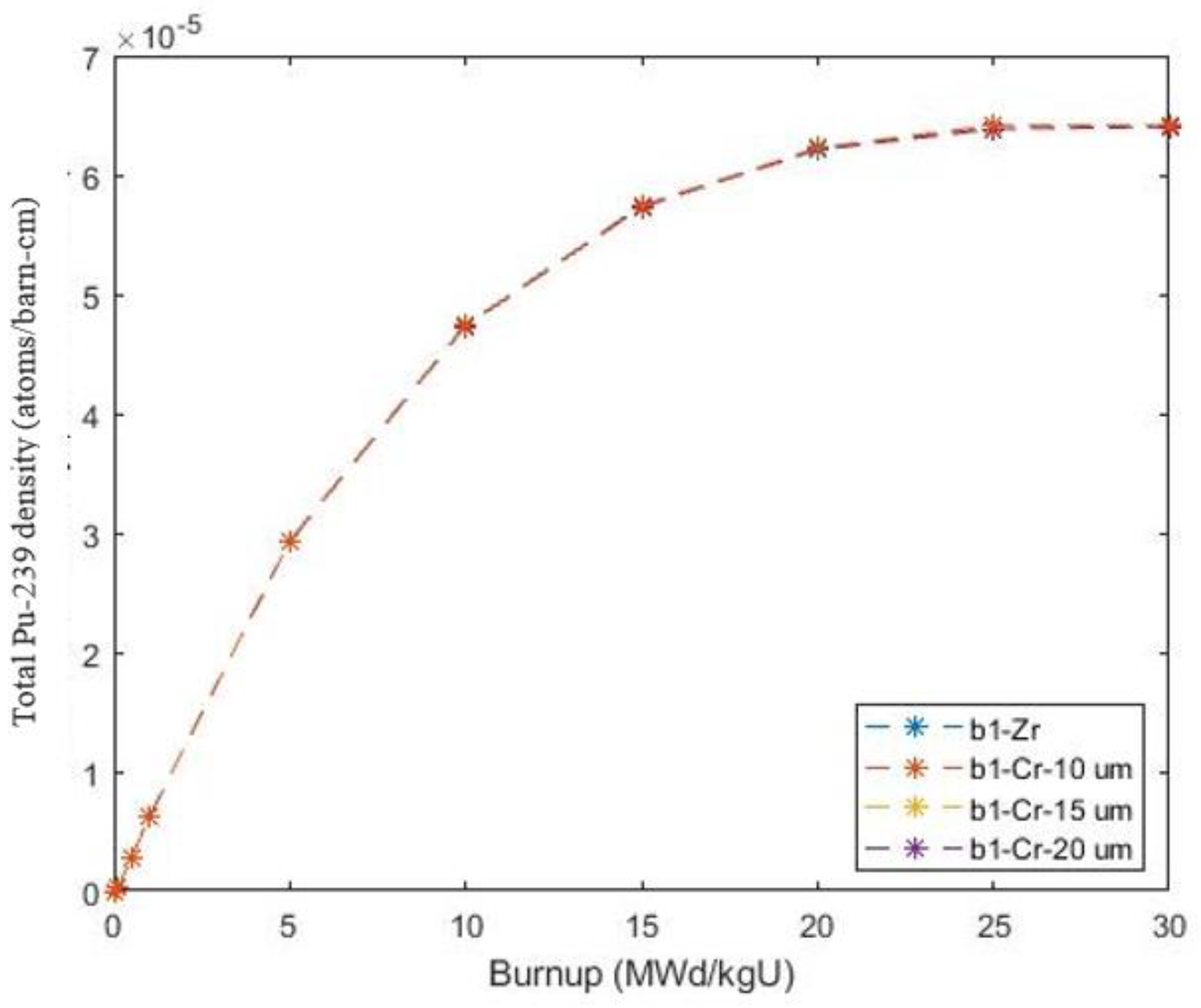
The 239Pu accumulation during the fuel life cycle was analyzed for the b1 APR-1400 fuel assembly type, as presented in Figure 9. In general, the increased 239Pu content throughout the cycle in the presence of the hardening thermal neutron spectrum leads to a significant reduction in the fuel cycle length for the molded fuel.
As expected, in the case of thin coating thickness, the changes in 239Pu content during the fuel life cycle were almost identical to those in the reference fuel-cladding system material, and the chromium-coated cladding with various thicknesses (10 µm, 15 µm, and 20 µm) does not have a major impact on the plutonium production throughout the fuel life cycle. Despite the high absorption cross section of the coating material, the thermal spectra of all types of cladding did not experience any softening or hardening in the thermal energy range (Figure 7).

4. Two-Dimension Full Core Calculation

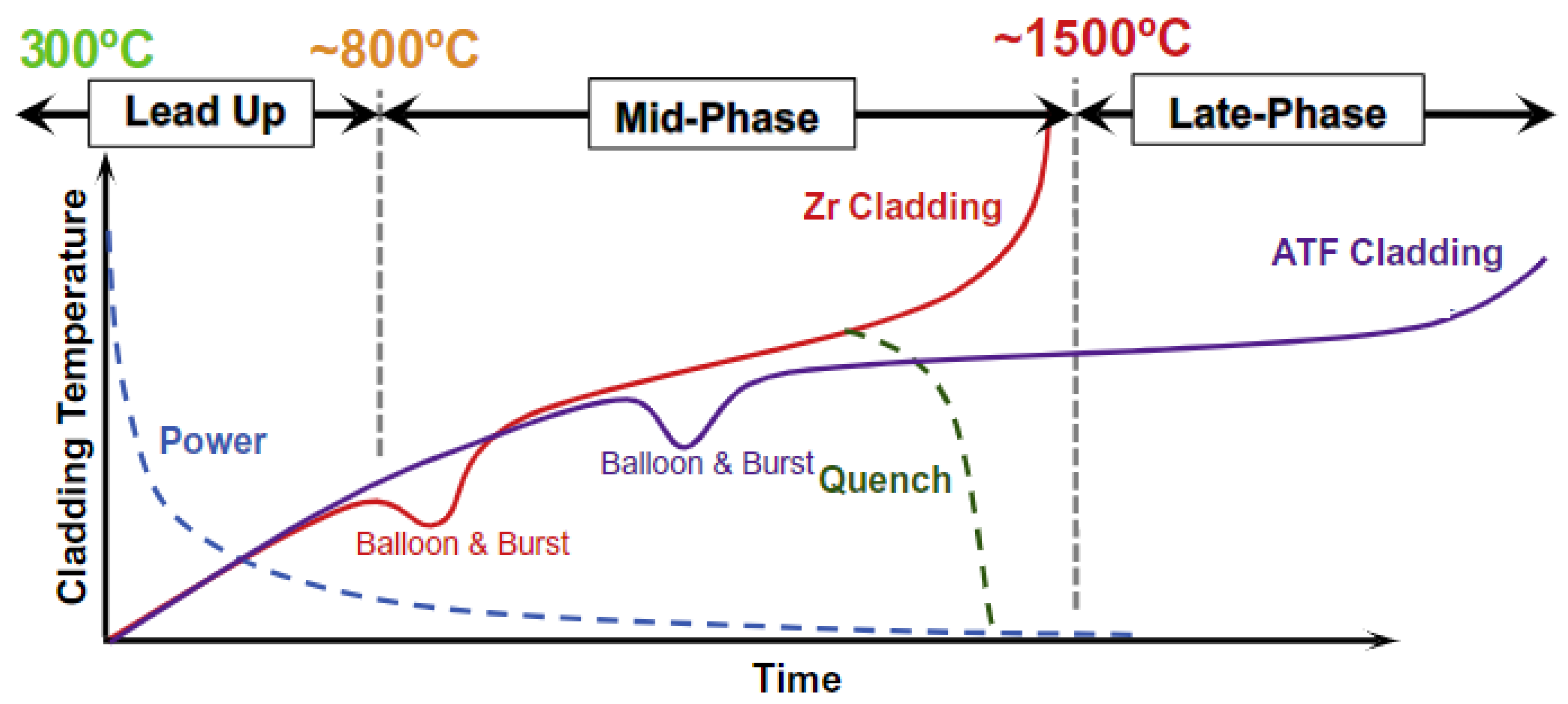
A two-dimensional APR-1400 full core was modeled, in which all the reactor fuel assemblies were modeled and placed accordingly in the core based on the core layout configuration presented in Figure 2 For both Zr–U and Zr–Cr–U fuel-cladding systems, neutronics analyses such as effective multiplication factor and thermal neutron radial power profiles were carried out and compared to enhance reactor safety without a neutronics penalty. Figure 10 shows a broad overview of the LWR degradation process for ATF materials compared with conventional cladding systems (Zircaloy).
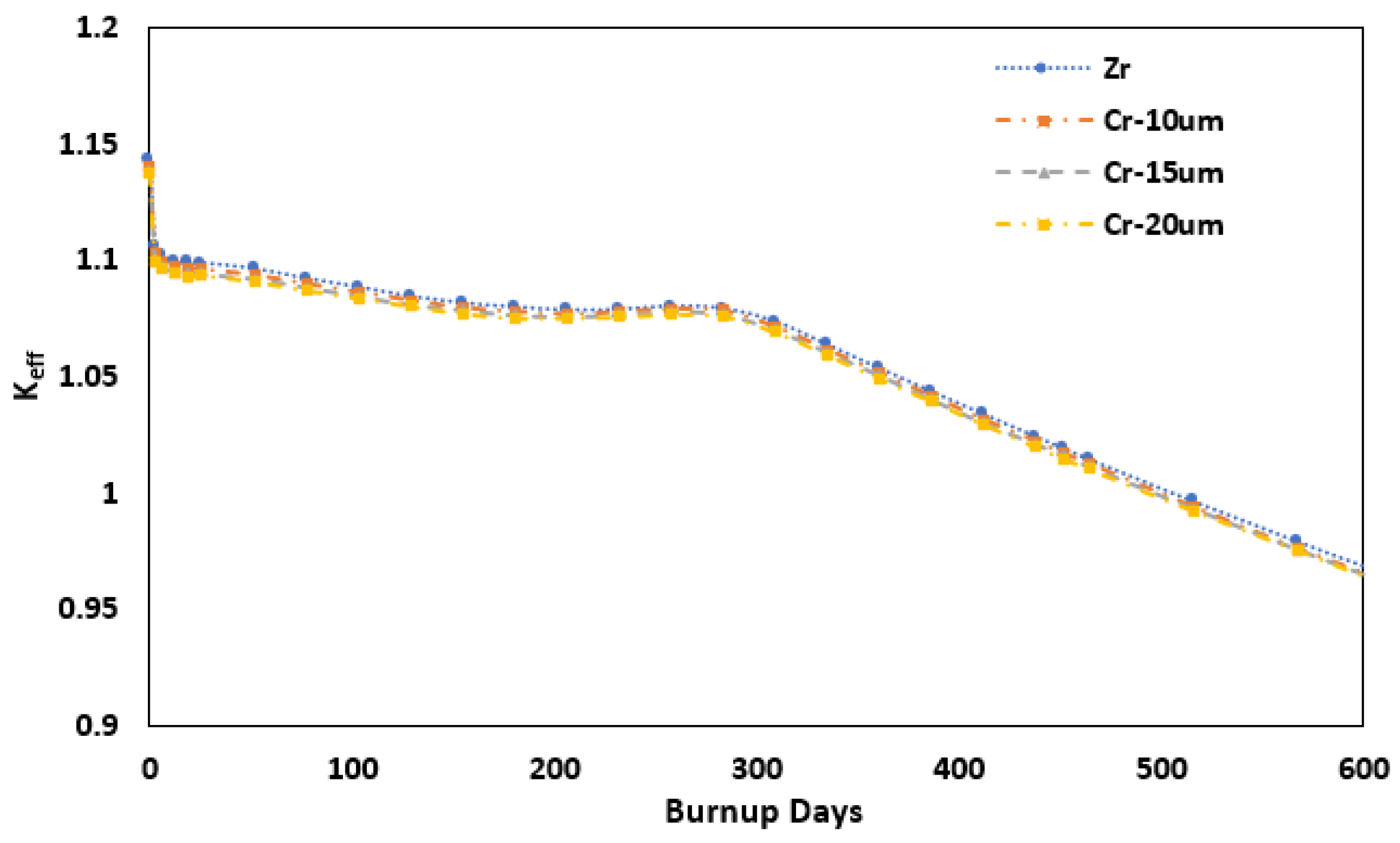
Figure 11 shows a comparison between the APR-1400 effective multiplication factor (keff) between the reference fuel-cladding system, and the chromium-coated fuel-cladding system. The behavior of the multiplication-factor throughout the fuel life cycle for the modeled fuel systems is almost identical for all cases, and the values of the keff at the BOC are about 1.14332 ± 0.0002, 1.14057 ± 0.0002, 1.13845 ± 0.0003, and 1.13723 ± 0.0004 for Zr–U, Zr–Cr–U-10 µm, Zr–Cr–U-15 µm, and Zr–Cr–U-20 µm coating thickness, respectively. Figure 12 presents the reactivity difference for different thicknesses (10 µm, 15 µm, and 20 µm) of cladding coating with respect to the reference fuel-cladding system (Zr–U). Obviously, the chromium has a larger cross section for the absorption of a thermal neutron, but because of the thin thickness (in the range of µm) of the coating material, it does not have a significant influence on the values of keff compared with the original cladding system (Zr–U). The reactivity differences at the BOC for the APR-1400 reactor core between the Zr–U and Zr–Cr–U systems are about −241.0 pcm, −427.0 pcm, and −535.0 pcm for Zr–Cr–U-10 µm, Zr–Cr–U-15 µm, and Zr–Cr–U-20 µm coating thickness, respectively. The tendency of the multiplication factor for 10 µm chromium coating during the fuel life cycle, and the low reactivity difference to the reference fuel-cladding system make it more adaptable than other coating thicknesses (15 µm, and 20 µm) for the APR-1400 reactor core. which makes it the favorable choice due to the thin thickness layer to improve the fuel-cladding system thermomechanical properties due to the lowest impact on the neutronics parameters.
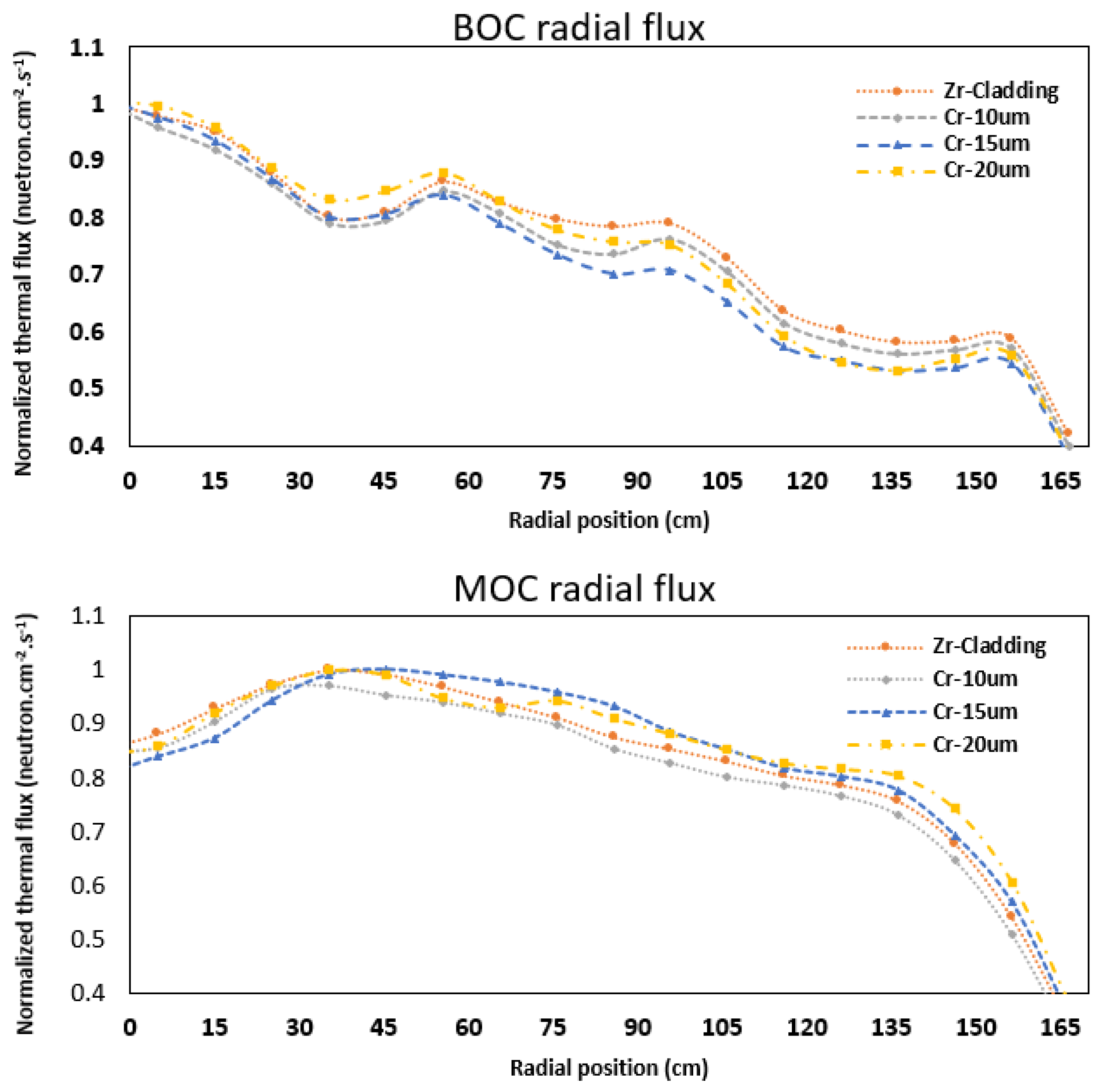
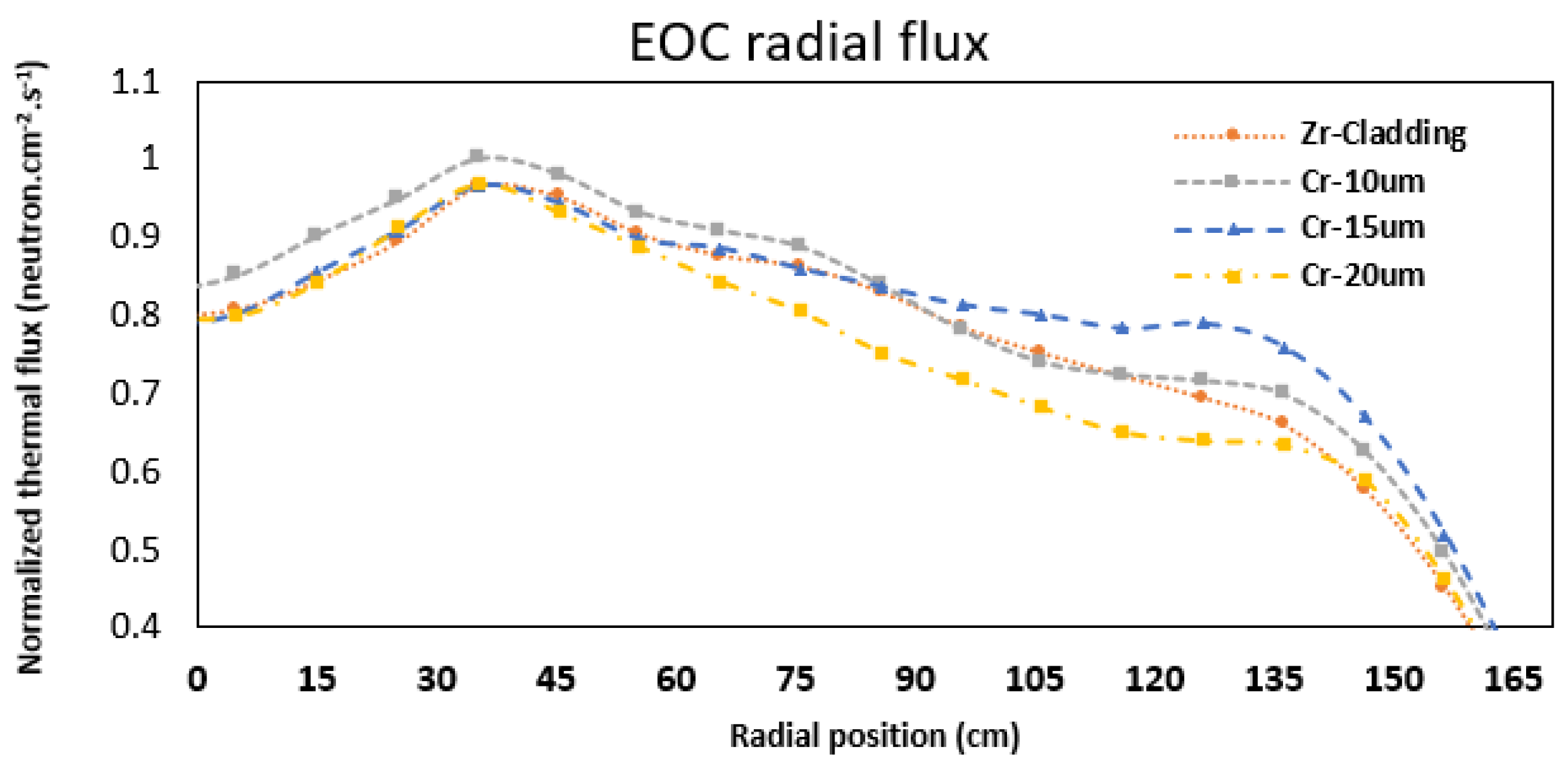
The fission products released throughout the fuel life cycle can be monitored since some isotopes would initiate fission reactions while others would impede them. The record of isotopic evolution plays an integral part in setting the parameters of the control methods, such as boron concentration in the coolant overtime. These fission products also affect the power and flux distribution in the core at various fuel burnup levels during the fuel life cycle. Figure 13 presents the radial neutron flux for the APR-1400 two-dimensional reactor core at the BOC, middle of the cycle (MOC), and end of the cycle (EOC). As observed, the effect of adding cladding chromium coating with different thicknesses is obvious, and the radial flux profiles are almost symmetrical on both sides of the APR-1400 reactor core, where it is maximum in the center and decreases toward the APR-1400 reactor core boundary at the BOC. At the BOC, it can be noticed that the tendency of the radial neutron flux for all core models is very similar. The reference cladding and the proposed chromium-coated cladding with various thicknesses show the highest thermal flux at the center of the core and gradually decrease toward the core peripheral region. At the MOC and EOC, the accumulation of the fission products within the reactor core leads to a lowering of the normalized radial neutron flux at the center of the core, with the maximum value is around 35.0 CM in the radial position from the center. All the radial flux profiles (BOC, MOC, and EOC) for reference cladding and chromium-coated cladding with different thicknesses (10 µm, 15 µm, and 20 µm) do not show a substantial neutronics penalty for the APR-1400 reactor core. From Figure 13, it is obvious that adding an additional coating layer to the reference cladding does not have a significant impact on the radial thermal flux profile for thermal neutrons in the APR-1400 reactor core.

5. Conclusions

In general, severe accident progression in LWRs is influenced by the reactor response system during such events. ATFs such as chromium coating can affect the sequence and rate of this progression, thereby reducing the burden on the reactor safety response systems and providing enhanced thermomechanical properties as a coping time during a severe accident event. In this manner, utilizing chromium coating as a potential ATF material leads to enhancing the safety margins for nuclear power systems.
In this research, neutronics analyses were performed on APR-1400 fuel pin cells, various assemblies, and a two-dimensional reactor core for both Zr–U and Zr–Cr–U fuel-cladding systems. Comparisons were performed to determine the consequences of the absorption cross section of the thermal neutron to the new fuel cladding on neutronics parameters.
Due to the thin thickness of the chromium coating, both types of cladding systems (Zr–U and Zr–Cr–U) tend to have the same behavior of the multiplication factor, neutron flux, pin power distribution, and evolution of 239Pu content as the reference Zu–U fuel-cladding system. The large thermal-neutron absorption cross section of the chromium coating in the Zr–Cr–U fuel-cladding system does not have a significant impact on the neutronics parameters with the recommended thinness (10 µm, 15 µm, and 20 µm) in comparison with the reference system (Zr–U). The 10 µm coating thickness has a lower neutronics impact in all the analyses, which makes Zr–Cr–U-10 µm one of the best candidates as an alternative cladding material.
In future work, three-dimensional analyses of the APR-1400 reactor core will be performed to estimate the fuel cycle cost for the new fuel-cladding system for the equilibrium cycle of the APR-1400 core, and more research will be conducted on severe accident analysis progression for the potential ATF cladding in the APR-1400 core design to enhance the safety margins in the reactor system.

Author Contributions

Conceptualization, M.A. and S.A.A.; methodology, M.A.; software, M.A.; validation: S.A.A.; formal analysis, M.A.; investigation, M.A. and S.A.A.; resources, S.A.A.; data curation, M.A.; writing—original draft preparation, M.A. and S.A.A.; writing—review and editing, M.A. and S.A.A.; visualization, M.A.; supervision, S.A.A.; project administration, S.A.A.; funding acquisition, S.A.A. All authors have read and agreed to the published version of the manuscript.

Funding

This research was supported by the UAE Ministry of Education (CRPG-2019, Grant No.: 1570604539) and the Emirates Nuclear Technology Center (ENTC), Khalifa University of Science and Technology, UAE.

Institutional Review Board Statement

Not applicable.

Informed Consent Statement

Not applicable.

Data Availability Statement

The datasets used and/or analyzed during the current study are available from the corresponding author on reasonable request.

Conflicts of Interest

The authors declare no conflict of interest.

References

  1. Allen, P.L.; Ford, L.H.; Shennan, J.V. Nuclear Fuel Coated Particle Development in the Reactor Fuel Element Laboratories of the U.K. Atomic Energy Authority. Nucl. Technol. 1977, 35, 246–253. [Google Scholar] [CrossRef]
  2. Zinkle, S.; Terrani, K.; Gehin, J.; Ott, L.; Snead, L. Accident tolerant fuels for LWRs: A perspective. J. Nucl. Mater. 2014, 448, 374–379. [Google Scholar] [CrossRef]
  3. Bocock, G.; Oelrich, R.; Ray, S. Westinghouse EnCore registered accident tolerant fuel. Innovations for the future. Atw. Int. Z. Kernenerg. 2018, 63, 442–446. [Google Scholar]
  4. Yeom, H.; Maier, B.; Johnson, G.; Dabney, T.; Lenling, M.; Sridharan, K. High temperature oxidation and microstructural evolution of cold spray chromium coatings on Zircaloy-4 in steam environments. J. Nucl. Mater. 2019, 526, 151737. [Google Scholar] [CrossRef]
  5. Kim, H.-G.; Kim, I.-H.; Jung, Y.-I.; Park, D.-J.; Park, J.-Y.; Koo, Y.-H. Adhesion property and high-temperature oxidation behavior of Cr-coated Zircaloy-4 cladding tube prepared by 3D laser coating. J. Nucl. Mater. 2015, 465, 531–539. [Google Scholar] [CrossRef]
  6. Fejt, F.; Ševeček, M.; Frybort, J.; Novák, O. Study on neutronics of VVER-1200 with accident tolerant fuel cladding. Ann. Nucl. Energy 2019, 124, 579–591. [Google Scholar] [CrossRef]
  7. Charit, I. Accident Tolerant Nuclear Fuels and Cladding Materials. JOM 2018, 70, 173–175. [Google Scholar] [CrossRef]
  8. Younker, I.; Fratoni, M. Neutronic evaluation of coating and cladding materials for accident tolerant fuels. Prog. Nucl. Energy 2016, 88, 10–18. [Google Scholar] [CrossRef]
  9. Mouche, P.; Evans, A.; Zhong, W.; Koyanagi, T.; Katoh, Y. Effects of sample bias on adhesion of magnetron sputtered Cr coatings on SiC. J. Nucl. Mater. 2021, 556, 153251. [Google Scholar] [CrossRef]
  10. Barrett, K.E.; Teague, M.P.; Van Rooyen, I.J.; Bragg-Sitton, S.M.; Ellis, K.D.; Glass, C.R.; Roth, G.A.; McHugh, K.M.; Garnier, J.E.; Griffith, G.W.; et al. Engineering Challenges of LWR Advanced Fuel Cladding Technology in Preparation for In-Reactor Demonstrations; Oak Ridge National Lab (ORNL): Oak Ridge, TN, USA, 2012.
  11. Yang, J.; Steinbrück, M.; Tang, C.; Große, M.; Liu, J.; Zhang, J.; Yun, D.; Wang, S. Review on chromium coated zirconium alloy accident tolerant fuel cladding. J. Alloys Compd. 2022, 895, 162450. [Google Scholar] [CrossRef]
  12. George, N.M.; Terrani, K.; Powers, J.; Worrall, A.; Maldonado, I. Neutronic analysis of candidate accident-tolerant cladding concepts in pressurized water reactors. Ann. Nucl. Energy 2015, 75, 703–712. [Google Scholar] [CrossRef]
  13. Pasamehmetoglu, K.; Massara, S.; Costa, D.; Bragg-Sitton, S.; Moatti, M.; Kurata, M.; Iracane, D.; Ivanova, T.; Bischoff, J.; Delafoy, C.; et al. State-of-the-Art Report on Light Water Reactor Accident-Tolerant Fuels (No. NEA—7317); Organisation for Economic Co-Operation and Development: Paris, France, 2018.
  14. Terrani, K.; Zinkle, S.; Snead, L. Advanced oxidation-resistant iron-based alloys for LWR fuel cladding. J. Nucl. Mater. 2014, 448, 420–435. [Google Scholar] [CrossRef]
  15. Alaleeli, M.M.; Alameri, S.A.; Alrwashdeh, M. Neutronic Analysis of SiC/SiC Sandwich Cladding Design in APR-1400 under Normal Operation Conditions. Energies 2022, 15, 5204. [Google Scholar] [CrossRef]
  16. Alrwashdeh, M.; Alameri, S.A. SiC and FeCrAl as Potential Cladding Materials for APR-1400 Neutronic Analysis. Energies 2022, 15, 3772. [Google Scholar] [CrossRef]
  17. Alrwashdeh, M.; Alameri, S.A. Preliminary neutronic analysis of alternative cladding materials for APR-1400 fuel assembly. Nucl. Eng. Des. 2021, 384, 111486. [Google Scholar] [CrossRef]
  18. Do, M.; Nguyen, X.H.; Jang, S.; Kim, Y. Physics study for high-performance and very-low-boron APR1400 core with 24-month cycle length. Nucl. Eng. Technol. 2020, 52, 869–877. [Google Scholar] [CrossRef]
  19. Salazar, D.; Franceschini, F.; Petrarca, A.; Godfrey, A.T.; Stimpson, S.G.; Evans, T.M.; Collins, B.S.; Gentry, C.A. AP1000 PWR Cycle 1 Hfp Depletion Simulations with Vera-CS; Oak Ridge National Lab (ORNL): Oak Ridge, TN, USA, 2016.
  20. Alnoamani, Z.; Alameri, S.A.; Elsawi, M. Neutronic and Fuel Performance Evaluation of Accident Tolerant Fuel Concepts in APR1400 Reactor. Transactions 2018, 118, 1010–1013. [Google Scholar]
  21. Fridman, E.; Leppänen, J. On the use of the Serpent Monte Carlo code for few-group cross section generation. Ann. Nucl. Energy 2011, 38, 1399–1405. [Google Scholar] [CrossRef]
  22. Leppänen, J.; Pusa, M.; Viitanen, T.; Valtavirta, V.; Kaltiaisenaho, T. The Serpent Monte Carlo code: Status, development and applications in 2013. Ann. Nucl. Energy 2015, 82, 142–150. [Google Scholar] [CrossRef]
  23. van der Marck, S.C. Benchmarking ENDF/B-VII.1, JENDL-4.0 and JEFF-3.1.1 with MCNP6. Nucl. Data Sheets 2012, 113, 2935–3005. [Google Scholar] [CrossRef]
  24. Alrwashdeh, M. 239Pu evaluation comparison study. Ann. Nucl. Energy 2018, 118, 313–316. [Google Scholar] [CrossRef]
  25. Stanisz, P.; Oettingen, M.; Cetnar, J. Development of a Trajectory Period Folding Method for Burnup Calculations. Energies 2022, 15, 2245. [Google Scholar] [CrossRef]
  26. Alrwashdeh, M.; Kan, W. U233 data evaluation for criticality study. J. Nucl. Eng. Radiat. 2016, 2, 034501. [Google Scholar] [CrossRef]
  27. Alrwashdeh, M. Covariance data evaluation for 233U. Appl. Radiat. Isot. 2018, 133, 105–110. [Google Scholar] [CrossRef]
  28. JAEA Nuclear Data Center Home Page. Available online: https://wwwndc.jaea.go.jp/ (accessed on 16 February 2022).
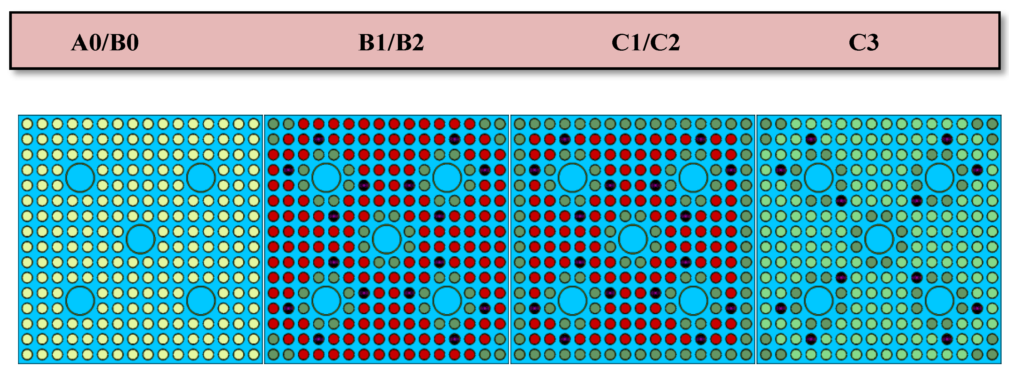
Figure 1. Fuel assemblies’ cross-sectional view.
Energies 15 08008 g001
Figure 2. Fuel loading pattern.
Energies 15 08008 g002
Figure 3. Unit cell infinite multiplication factor vs. burnup days with different enrichments: (A) 1.68 wt %, (B) 2.64 wt %, (C) 3.14 wt %, (D) 3.46 wt %.
Energies 15 08008 g003
Figure 4. Capture cross section comparison between Cr and Zr [28].
Energies 15 08008 g004
Figure 5. Evolution of Pu-239 inventory for Zircaloy and chromium-coating cladding systems.
Energies 15 08008 g005
Figure 6. Kinf versus burnup days and fuel reactivity compared to the reference cladding for c3 and b1 assemblies.
Energies 15 08008 g006aEnergies 15 08008 g006b
Figure 7. Neutron flux spectrum for b1 APR-1400 fuels assembly.
Energies 15 08008 g007
Figure 8. Pin power distribution at BOC comparison between reference cladding and coated cladding 10 µm, 15 µm, and 20 µm, respectively, for b1 fuel assembly.
Energies 15 08008 g008aEnergies 15 08008 g008b
Figure 9. Pu inventory during the life cycle of b1 fuel assembly.
Energies 15 08008 g009
Figure 10. LWR accident evolution scenario for reference cladding and ATF cladding [2].
Energies 15 08008 g010
Figure 11. Effective multiplication factor comparison versus burnup days for APR-1400 reactor core.
Energies 15 08008 g011
Figure 12. Reactivity difference with respect with the reference cladding material.
Energies 15 08008 g012
Figure 13. Radial neutron fluxes across the APR-1400 reactor core.
Energies 15 08008 g013aEnergies 15 08008 g013b
Table 1. APR-1400 core design parameters [20].
ItemValue
Fuel assemblies241
Number of control assemblies93
Number of fuel rod locations56,876
APR-1400 Core diameter, m3.647
Gd2O3 concentration 8.0 w/o
Gd2O3 per assembly 12, 16
Table 2. Cladding material composition [15,16].
Composition (wt %)Cross Section (Barn)
Cladding MaterialDensity (g/cm3)ZrSnFeCr
Zircaloy-46.5797.71.10.11.10.185
Cr7.19---------100.0 *3.070
* Cr-Isotope Mass Number ([at %]): Cr-50 (4.34); Cr-52 (83.79); Cr-53 (9.50); Cr-54 (2.37).
Table 3. Assembly specifications.
Assembly TypeNumber of Assemblies Enrichment (w/o)Fuel RodsGd2O3 Rods
a0851.68236-
b0203.14236-
b1123.14/2.64172/5212
b2483.14/2.64168/5216
c0283.64/3.14184/52-
c1163.64/3.14168/5216
c2243.64/3.14120/10016
c383.64/3.14172/5212
Table 4. Pin cell geometries.
Case #Pellet Radius (mm)He Gap
(µm)
Clad Thickness
(µm)
Coating Thickness
(µm)
wt %
Zr–U4.095085.0570.0---1.68, 2.64, 3.14, 3.46
Zr–Cr–U4.095085.0560.0, 555.0, 550.010.0, 15.0, 20.01.68, 2.64, 3.14, 3.46
Table 5. kinf values at beginning of the cycle (BOC) for different pin cell enrichment for both types of cladding materials.
Fuel Enrichment (wt %)kinf, Zr–Ukinf, Cr-Zr–UReactivity Change (pcm)
10 µm15 µm20 µm10 µm15 µm20 µm
1.681.16109 ± 0.000141.15742 ± 0.000141.15550 ± 0.000131.15341 ± 0.00013−317.0−484.0−666.0
2.641.24543 ± 0.000141.24237 ± 0.000131.24050 ± 0.000141.23880 ± 0.00014−246.0−397.0−535.0
3.141.31111 ± 0.000131.30774 ± 0.000131.30639 ± 0.000141.30482 ± 0.00014−257.0−361.0−482.0
3.461.33424 ± 0.000131.33139 ± 0.000141.33012 ± 0.000141.32860 ± 0.00014−214.0−310.0−425.0
Table 6. kinf values and reactivity difference at BOC for APR-1400 fuel assemblies.
Fuel Enrichment (wt %)kinf, Zr–Ukinf, Cr-Zr–U Δρ (pcm)
10 µm15 µm20 µm10 µm15 µm20 µm
a01.03920 ± 0.00031.03645 ± 0.00031.03435 ± 0.00031.03249 ± 0.0003−265.0−469.0−650.0
b01.23772 ± 0.00041.23580 ± 0.00041.23414 ± 0.00041.23312 ± 0.0004−155.0−290.0−373.0
b11.05485 ± 0.00061.05369 ± 0.00061.05332 ± 0.00061.05169 ± 0.0006−110.0−145.0−300.0
b21.00720 ± 0.00071.00361 ± 0.00071.00193 ± 0.00061.00164 ± 0.0006−358.0−526.0−555.0
c01.26845 ± 0.00041.26510 ± 0.00041.26509 ± 0.00041.26268 ± 0.0005−264.0−266.0−457.0
c11.05601 ± 0.00051.05357 ± 0.00051.05313 ± 0.00061.05132 ± 0.0007−232.0−237.0−446.0
c21.04670 ± 0.00071.04493 ± 0.00071.04233 ± 0.00061.04233 ± 0.0006−169.0−419.0−419.0
c31.10449 ± 0.00051.10263 ± 0.00051.10116 ± 0.00061.10040 ± 0.0006−167.0−302.0−372.0
Publisher’s Note: MDPI stays neutral with regard to jurisdictional claims in published maps and institutional affiliations.