Abstract
As one of the effective solutions to recover waste heat, absorption refrigeration systems are used in various industrial or refrigeration places. Flat-plate falling-film absorption is one of the newer types, and the lattice Boltzmann method (LBM) has certain advantages compared with the traditional numerical simulation method. In this work, an LBM is used to analyze flat-plate falling-film absorption. Using the additional calculation of the pressure by the pseudo-force model, a lithium bromide–water working fluid–heat and mass transfer model driven by steam partial pressure is realized. The results show that the turbulence generated in the surface wave has a favorable effect on the absorption process; the degree of turbulence gradually decreases with the increase in the Reynolds number, which weakens the increasing effect of the surface wave on the absorption. When the Reynolds number is moderate, the solitary wave flows forward relative to the front thin liquid film, which promotes concentration and temperature diffusion inside the liquid film and inside the solitary wave. The model of falling-film flow under vibration environment is realized by using the characteristic of imposing inertial force in the model by pseudo-force method. The results show that vibration has a favorable effect on liquid film absorption, increasing the amplitude can increase the gas–liquid contact area and obtain a lower average film thickness, while increasing the vibration frequency can promote the internal diffusion of the solution.
1. Introduction
With the emphasis on energy saving and emission reduction, the application and research of lithium bromide absorption refrigeration systems in the industrial and civil fields of artificial environment and air conditioning have attracted more and more attention. Among them, the absorption process affects the performance of the entire absorption system. In order to improve the heat and mass transfer performance during the absorption process, different types of absorbers have been studied. Horizontal tubular falling-film absorbers have been widely used and studied in absorption units, such as Choudhury et al. [1], Hoffmann et al. [2], Jeong and Garimella [3], Francés and Ojer [4], Sultana et al. [5], and Islam [6]. However, a horizontally arranged absorber has difficultly reducing floor space, thus limiting the development of the unit to miniaturization. The vertical absorber, which occupies a relatively small area, has attracted people’s attention. Under the same Reynolds number, when the solution falls along the vertical wall, the coverage rate (wetting) of the tube wall is better than that of the horizontal one, the film thickness is evenly distributed along the flow direction, and the heat and mass transfer effect is better than the falling-film absorption outside the horizontal tube. Miller and Keyhani [7], Medrano et al. [8], Takamatsu et al. [9], and Karami and Farhanieh [10] carried out experimental and numerical research on vertical tube or vertical plate absorbers. To enhance the heat and mass transfer process during the absorption process, additives such as surfactants and nanoparticles were also employed [11,12,13,14]. In addition, vibration proved to be an effective way to enhance heat transfer [15].
Compared with the traditional numerical simulation method, the lattice Boltzmann method (LBM) is simple in calculation, efficient in operation, high in data accuracy, and very friendly to programming. It has great advantages in the study of multiphase flow problems such as plate falling-film absorption. Kang et al. [16] used the LBM pseudo-force scheme to study the flow state of droplets along the wall under different contact angle conditions. Hantsch and Gross [17] realized a complete falling-film flow model and carried out flow simulations for different Reynolds numbers under the assumption of isothermal environment, obtaining a fluctuation relationship consistent with the actual situation. Shi et al. [18] constructed a periodic model of falling-film flow, omitting the difference between the entrance and exit, obtaining a local liquid film distribution.
The above studies have contributed to the application of the LBM model to the falling-film flow or falling-film absorption process, however, there is still room for improvement in the use of LBM to simulate vertical plate falling-film absorption. In the falling-film absorption process, the steam transfer power comes from the vapor pressure difference between the solution and the environment, and there is no LBM pseudo-force model that relies on this principle to realize mass transfer. Many studies have simulated the falling-film flow under periodic vibration state by periodically changing the inlet boundary conditions, while the actual vibration phenomenon should be the disturbance of the entire flow field by the inertial force. To overcome these problems, this paper uses a Python script to build a vertical plate falling-film flow LBM model. Using the nonlinear increasing characteristic of pressure to density in the pseudo-force method, the heat and mass transfer across the liquid film depending on the water vapor partial pressure difference is realized in the LBM model. Then, by introducing the vibration inertial force into the pseudo-force model, the fluctuation effect of the falling-film flow in the process of simple harmonic vibration is simulated.
2. Mathematic Model
Most of the literature analyzed the falling-film absorption process from a two-dimensional perspective. Due to the high construction cost of the three-dimensional lattice Boltzmann model, the two-dimensional D2Q9 model is also used to study the liquid film flow in the longitudinal section. In the lattice Boltzmann model, the D2Q9 model is used to simulate a two-dimensional flow field, in which the particles on the lattice node are distributed in 9 velocity directions in the form of probability. The particle distribution function f is represented by the speed discrete form of the Boltzmann equation:
Shan and Chen [19] proposed a pseudo-potential scheme to simulate a multicomponent multiphase flow model. They embodied the interaction of fluids through nonlocal forces in the flow field. The potential function as follows:
To implement the evaluation of the potential function in the LBM model, the Green function G is only valid for adjacent grid points, and the potential function is discretized as follows:
Fluid density and momentum are statistical results of distribution functions that satisfy the following equations:
The fluid evolution relies on equilibrium distribution , which is related to density and equilibrium velocity. To implement the force applied into the model, Shan and Doolen [20] proposed a fluid equilibrium velocity as follows:
The discretized form of is:
By setting up passive scalars, the temperature and concentration changes in the flow field are realized by using the double distribution function. Establish temperature distribution functions and concentration distribution functions gi and hi that conform to the evolution law of the lattice Boltzmann model:
The dimensionless relaxation time requirements for temperature and concentration are obtained as follows:
The fluid pressure of the traditional LBM model is a single-valued function of the fluid density. In the pseudo-force model, the fluid pressure also considers the potential function:
The lattice virtual pressure driving the concentration migration can be expressed as:
In the falling-film absorption process, the mass transfer power of vapor transmission across the liquid film comes from the vapor partial pressure difference on both sides of the liquid film. Motivation is related to vapor partial pressure. The vapor partial pressure in the liquid film is obtained using the empirical formula for vapor partial pressure proposed by McNeely [21]:
P is the partial pressure of water vapor inside the solution, kPa; TD is the dew point temperature of the solution in the current state, °C.
The empirical formula for dew point temperature TD is:
where X is the solution mass fraction, wt.%; T is the solution temperature, °C.
The correlation coefficients of Equations (14) and (15) are referred from literature [21].
Applying the pseudo-force scheme to the concentration distribution function, and combining the obtained lattice pressure with Equation (13), we can obtain:
Substituting the effective concentration into Equation (3), we obtain:
The motion law of the temperature distribution function is similar to that of the concentration distribution function, and the gradient ratio of temperature and concentration near the liquid film satisfies:
where Δh is the heat of absorption generated by the water vapor absorbed by the solution, J/kg; ρ is the density of the solution, kg/m3; D is the diffusion coefficient in the solution, m2/s; and λ is the thermal conductivity of the solution, W/(K·m).
The effective temperature is obtained using the same approach:
We added an alternating force to the model to study how the device works under vibration. The alternating force is shown as simple harmonic vibration, and the direction is perpendicular to the heat exchange wall, as shown in Figure 1.
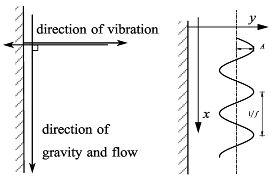
Figure 1.
Vibration direction and vibration type.
Amplitude A and vibration frequency f are independent variables; it can be known that the vibration trajectory of the device is:
where S is the vibration displacement of the device, m; t is the current flow time, s.
Ignoring the damping of the vibration of the device by the inertia of the fluid in the flow field, during the vibration process, the reaction force received by the internal fluid is:
From the above, a falling-film absorption flow model with the impact of vibration can be obtained.
3. Parameter Settings and Model Validation
The actual physical scale of the model requires additional dimensional calculations based on the constant assumption of the local speed of sound based on the LBM equation.
The liquid film thickness is set to 10 grid distances, and the length ratio is obtained:
The velocity scale and time scale of the model obtained from the actual sound velocity of the fluid are:
Using the length ratio and the time ratio, the viscosity coefficient and the gravitational acceleration can be obtained in the same way. For a typical lattice Boltzmann model, densities (and likewise temperature and concentration) are used as scalars, and their values only produce proportional changes to the results. We can temporarily set them to numerical values that are convenient to calculate, such as setting the density to a constant 1 and multiplying the actual value of the density before converting it to an actual physical quantity (see the Table 1).

Table 1.
Falling-film absorption parameter settings.
3.1. Parameter Settings
The basic design of the falling-film flow model is shown in Figure 2, using the D2Q9 plane model.
Figure 2.
Falling-film flow diagram.
The liquid film flow length is set to 100 × δ, and the vibration direction is normal to the film flow direction. The bottom of the model is the rebound boundary, the right side is the free outlet boundary, the left side below the liquid film thickness is the velocity inlet boundary, and the rest is the pressure inlet boundary.
Referring to the range of Re numbers used by previous researchers, for example, Rastaturin et al. [22] selected 40 and 75, Lu and Xiao [23] selected 1 to 20, this paper selected 5, 20, and 40. The angle between the plate and the ground is set to 90°. The parameters related to the model are set referring to the actual operation parameters, as shown in the Table 1.
Taking the Re number 5 as the flow parameter of conventional falling-film flow, 3 vibration conditions are set, respectively, in which the amplitude parameter is measured in the unit of liquid film thickness, and the working condition parameters are shown in the Table 2.
Table 2.
Vibration condition setting.
3.2. Model Validation
Using the falling-film absorption parameter settings used in the paper by Kawae et al. [24], the temperature and concentration curves of the liquid film surface under stable laminar flow were intercepted for comparison, as shown in Figure 3. The comparison results show that the temperature change is in good agreement with the literature, and the concentration change is only slightly deviated from the literature.
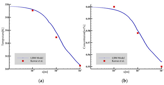
Figure 3.
The temperature and concentration profiles were compared with the results of Kawae et al. [24]. (a) Temperature comparison; (b) concentration comparison.
4. Results and Discussion
The running time of the model is limited to twice the characteristic time t0, where the characteristic time refers to the time it takes for the solution at the inlet to flow to the outlet of the plate.
4.1. Mass Transfer Flux and Liquid Film Surface Height
When the Reynolds number is 5 and the flow time is t = 0.28 t0, as shown in Figure 4a, the surface mass transfer flux surges in the inlet region, followed by a rapid decline to normal levels. When flow length reaches the peak position, the mass transfer flux decreases to a local minimum and turns to increase with the decrease in the liquid film height. On the surface distribution of the liquid film at this moment, the liquid film in front of the solitary wave is squeezed, resulting in a series of tiny fluctuations, and the mass transfer flux fluctuates in the opposite direction in this region. After the surface of the liquid film recovers to a gentle level, the surface mass transfer flux decreases monotonically with the flow distance until the flow field exits.
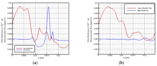
Figure 4.
Mass transfer flux and liquid film surface height as a function of flow distance, Re = 5. (a) t = 0.28 t0, (b) t = 2 t0.
When the flow time is t = 2 t0, as shown in Figure 4b, the solution absorbs steam in the feeding area with a greater intensity. The surface of the liquid film in the state of violent fluctuation has several small disturbances, which make the absorption process of the solution to the vapor also subject to positive disturbance, while the disturbance generated by the surface of the liquid film in the state of smooth flow is not enough to affect the absorption of the film surface, i.e., the transmission process. The overall mass flux declines and maintains at an average level of 0.003 to 0.004 kg/(m2s). When flow distance reaches the fluctuation region, the mass transfer flux changes in the opposite direction with the change in the liquid film surface height.
Analysis of the change law of the surface mass transfer flux when the Reynolds number is 5 shows that the mass transfer flux changes in the opposite direction with the surface height in the fluctuation region of the film surface: as the liquid film surface height rises, it decreases. However, even if the surface of the liquid film fluctuates violently, the overall change trend of the surface mass transfer flux is still not significantly different from that of the liquid film in a gentle state. Both the velocity and the inlet flow are low, so the mass transfer flux is not sensitive to changes in the liquid film surface.
When the Reynolds number is 20 and the flow time is t = 0.58 t0, as shown in Figure 5a, it can be seen that when the liquid film is in a state of violent fluctuation, the surface mass transfer flux begins to decrease after a certain distance behind the solitary wave and maintains a downward trend. At the front wave waist, the surface mass transfer flux reaches a local minimum. In the fluctuating state, the solitary wave front has a slender, thin liquid film, and the surface mass transfer flux begins to increase gradually in the region located in the slender, thin liquid film, indicating that the solution in the thin liquid film region gradually restores the strength of the vapor absorption. This can be explained by concentration and temperature distributions at this time. At inlet, when the liquid film region flows smoothly, the surface mass transfer flux gradually rises to the highest point, and then begins to decrease, indicating that the solution at the liquid film inlet has the greatest absorption strength for steam under steady state. When flowing to the fluctuating region near the outlet, the surface mass transfer flux shows an opposite trend with the change in the liquid film height, which is different from the change trend of the liquid film surface mass transfer flux in the state of severe fluctuation. The mass transfer flux in the state of severe fluctuation reaches a minimum value at the waist of the wave front, while the mass transfer flux in the state of smooth flow reaches a minimum value at the peak of the wave.
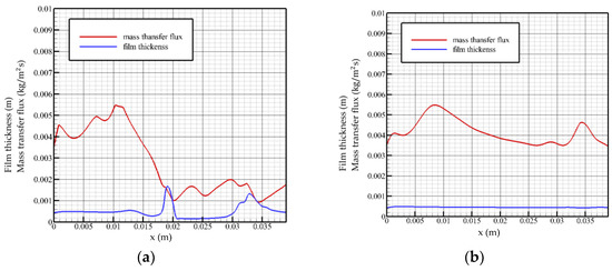
Figure 5.
Mass transfer flux and liquid film surface height as a function of flow distance, Re = 20. (a) t = 0.58 t0, (b) t = 2 t0.
When the Reynolds number is 20 and the flow time is t = 2 t0, as shown in Figure 5b, near the inlet, the surface mass transfer flux curve shows an upward trend, and the absorption strength of the solution to the vapor gradually increases in this region. Additionally, after reaching the highest point (x ≈ 0.008 m), it decreases gently, and the overall level of mass transfer flux at this time is more than 0.004 kg/(m2s). When the flow reaches the fluctuation region near the outlet, the mass transfer flux rises briefly with the disturbance of the liquid film. It can be seen that under the steady flow state, the liquid film fluctuation has a positive excitation on the surface mass transfer flux. When the liquid film height reaches the lowest point, the mass transfer flux curve rises briefly to reach the second peak value and then decreases with the recovery of the liquid film height.
When the Reynolds number is 40 and the flow time is t = 0.76 t0, as shown in Figure 6a, near the flow inlet, the mass transfer flux on the surface of the liquid film increases gradually. When the surface of the liquid film fluctuates, the mass transfer flux changes from a gentle change to a downward trend, and a local minimum occurs when the flow distance reaches the wavefront region (x ≈ 0.028 m), where the absorption strength of steam is weak. When reaching the trough position, the mass transfer flux turns to rise and has a local maximum value and then drops sharply with the steeply rising liquid film surface height. The thickness of the liquid film in the leeward side area decreases as a whole. At this time, due to the good heat exchange environment, the mass transfer flux gradually increases until the level of the inlet is restored. Liquid film fluctuations reduce the average mass transfer flux as a whole.
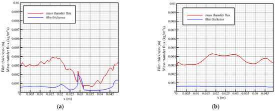
Figure 6.
Mass transfer flux and liquid film surface height as a function of flow distance, Re = 40. (a) t = 0.76 t0, (b) t = 2 t0.
When the flow time is t = 2 t0, as shown in Figure 6b, the change trend of the mass transfer flux is more gradual, and it gradually increases with the flow distance and maintains the overall highest level in the middle region of the flow plate.
When the Reynolds number is 40, the change curve of the mass transfer flux is not exactly opposite to the height of the liquid film surface, and the change curve has a hysteresis characteristic, that is, the location of the minimum value of the mass transfer flux curve lags behind the location of the peak of the wave. The mass transfer flux in the steady state gradually increases at the inlet position, and the overall absorption intensity of the solution in this region gradually increases. When the Reynolds number is 40, the fluctuating region of the liquid film is closer to the outlet, and the mass transfer flux curve fluctuates when it is located in the middle of the flow plate and remains above 0.004 kg/(m2s). It turns to descend when approaching the outlet and varies with the thickness of the liquid film.
Overall, the surface mass transfer flux decreases in the rising region of the liquid film thickness and rises in the falling region. The influence degree increases with the increase in the Reynolds number, and the change trend shows a hysteresis with the increase in the Reynolds number. When the wave crosses the thin liquid film, the concentration diffusion from the liquid film to the wave is promoted. The turbulent solution in the wave drives the solution in the thin liquid film with sufficient heat exchange between the wave front and the back of the wave and pulls it into the wave, which promotes the heat exchange in the wave. When the Reynolds number is low, only the phenomenon of intra-wave turbulence occurs. With the increase in the Reynolds number, the fluctuation phenomenon of the liquid film advancing relatively near the wall surface gradually becomes obvious. However, when the Reynolds number increases to 40, neither turbulence nor relative liquid film migration occurs during the fluctuation process, and the absorption effect is poor.
4.2. Concentration Distribution in Liquid Film
The concentration distribution in the liquid film at each moment is shown in Figure 7. When the Reynolds number is 5, the absorption effect of the windward surface is better in the initial fluctuation state of the flow. The concentration distribution inside the wave crest shows a counterclockwise disturbance. The absorbed steam on the windward side migrates counterclockwise with the flow in the wave to the leeward side of the solitary wave while diffusing; the absorption intensity of the steam in this area is low, and the absorption of the steam is relatively low. The contribution of the process is not large, so the accumulation of low-concentration solution in this area is beneficial to the smooth progress of the absorption process in other areas. Only when the solitary wave peak reaches a certain height will the phenomenon of spontaneous concentration migration within the wave occur, and when the solitary wave maintains its own height, the internal concentration will continue to migrate until the concentration in the wave reaches a uniform distribution.
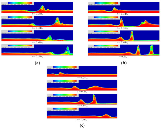
Figure 7.
The concentration distribution in the liquid film at each moment. (a) Re = 5, (b) Re = 20, (c) Re = 40.
At a Reynolds number of 20, in the wave foot area of the windward side of the solitary wave, the concentration of the solitary wave diffuses into the inner wave. The diffusion direction is opposite to the flow direction of the liquid film. There is a thin and thin liquid film behind this area, and the concentration is obviously low. The solitary wave has a faster flow velocity relative to the liquid film. When the thickness of the liquid film in front is sufficient, the fluctuation of the film surface will squeeze the liquid film in front. When the thickness of the liquid film on the front side is lower than a certain threshold, the fluctuation of the film surface no longer squeezes the liquid film on the front side but moves forward relative to the liquid film and finally continues to flow from the top of the film. The region maintains the original diffusion strength. The rear surface wave passes from above, causing the phenomenon that the concentration of the wave trough is reduced. After the low-concentration area is in contact with the high-concentration area, the concentration diffusion intensity increases, which is beneficial to the absorption of the slender and thin liquid film area.
At a Reynolds number of 40, the solution concentration near the inlet and on the windward side of the surface wave is lower. The concentration on the leeward side of the surface wave is always high, and there is a counterclockwise diffusion of the concentration inside the wave crest, but a high concentration band appears in the wave waist, which cuts off the low concentration areas of the wave crest and the wave trough. The surface fluctuation of the film firstly generates a wavelet above the solitary wave; then, the concentration diffusion in the wave is confined within the range of the subwave, and the concentration diffusion in the wave reduces the positive excitation effect of the absorption, which has an adverse effect on the absorption. In addition, the phenomenon of solitary waves flowing from above the low-concentration region in the thin liquid film still occurs. Due to the increase in the Reynolds number, the flow rate and velocity increase synchronously, and the ratio of the wave velocity to the velocity of the liquid film surface gradually decreases, so that the solitary wave gradually decreases. The forward motion of the wave relative to the slender, thin liquid film is not obvious and, finally, the effect of diffusion of the vapor concentration in the thin liquid film into the wave is not as effective as when the Reynolds number is 20.
4.3. Temperature Distribution in Liquid Film
The temperature distribution in the liquid film at each moment is shown in Figure 8. When the Reynolds number is 5, the temperature in the film gradually decreases with the flow distance, and gradually increases with the height from the wall. When the wave is generated, the motion of the wave pulls the low-temperature solution in this area into the wave. The contact area between the wave surface and the steam gradually increases, but the surface temperature rises insignificantly, which promotes the absorption process of the wave surface.
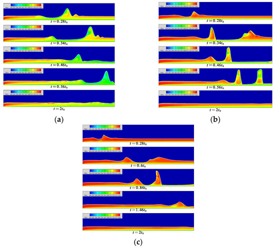
Figure 8.
The temperature distribution in the liquid film at each moment. (a) Re = 5, (b) Re = 20, (c) Re = 40.
When the Reynolds number is 20, the average flow rate of the liquid film increases, resulting in an insufficient heat transfer process of the solution. Therefore, when the liquid film flow reaches a gentle level, the minimum temperature of the solution surface is still much higher than the temperature of the cooling wall surface. In the fluctuating state, the mass of the fluctuating surface of the liquid film comes from the wave front and the back of the wave. At the moment of t = 0.34 t0 in Figure 8b, the mass of the slender and low-temperature thin liquid film goes to the wave waist of the front wave and the wave peak of the back wave, respectively, and its flow law is in line with the counterclockwise flow of the solution inside the wave. With the movement of the solitary wave, a high-temperature area appears in the middle part of the wave, which separates the upper and lower low-temperature areas. The upper low-temperature area comes from the supply of low-temperature solution on both sides of the wave; the lower low-temperature area comes from the low-speed flow near the heat exchange wall.
When the Reynolds number is 40, the temperature of the liquid film surface remains high. When the liquid film forms a region of lower film thickness, the low-temperature solution migrates to the wave surfaces on both sides. The migration of the solution is not obvious. When the solution migrates to the leeward side of the solitary wave, it is intercepted at the trough of the wavelet, so that the solution in the wave cannot conduct sufficient heat exchange. In the region with lower liquid film thickness on the back side of the wave, the tendency of the low-temperature solution to flow into the wave can be clearly found, but this part of the solution does not finally reach the wave surface. In this region, the flow of the solution into the wave is blocked. The generation of wavelets is not the direct cause of the blocked flow of the low-temperature solution. It may be that the increase in the Reynolds number slows down the counterclockwise flow of the solution in the wave, resulting in insufficient low-temperature solution at the bottom of the liquid film to be drawn into the film.
4.4. Absorption Effects with Vibration
The Reynolds number of 5 is selected to examine the effect of vibration on the absorption. The falling-film absorption effect under different vibration parameters is shown in Figure 9.
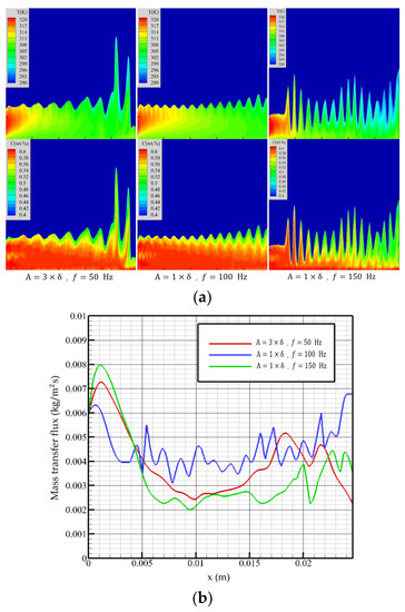
Figure 9.
Falling-film absorption effects with different vibration parameters. (a) Temperature (top figure) and concentration (bottom figure) distributions, (b) mass transfer flux curves of membrane surfaces by different vibration parameters.
In the vibration state with an amplitude of three times the film thickness and a frequency of 50 Hz, the surface of the liquid film produces continuous fluctuations, which increases the contact area of the film surface with the steam, reduces the overall film thickness, and improves the overall flow performance of the liquid film. The mass transfer flux begins to decrease after reaching the maximum value at the inlet position. Due to the lower vibration frequency, the fluctuation state of the liquid film is similar to that under non-equilibrium disturbance. The influence of the fluctuation at this time on the liquid film absorption process is not obvious. When flow distance reaches the violent fluctuation region, the mass transfer flux decreases with the liquid film height. At the exit, there is an upward trend.
When amplitude is one time the film thickness, and the frequency is 100 Hz, the liquid film fluctuates regularly, and the fluctuation is weaker than that of high amplitude and low frequency. However, the higher frequency makes the solution in the liquid film fully disturbed, which promotes the diffusion of temperature and concentration in the film. When the flow distance is close to the outlet, the mass transfer flux increases with the flow distance and then begins to decline. The overall trend is not significantly different from that of high amplitude and low frequency.
When the amplitude is one time the film thickness, and the frequency is increased to 150 Hz, the higher vibration frequency causes the liquid film to fluctuate violently; the violent fluctuation breaks the characteristics of high absorption intensity at the entrance, and the mass transfer flux first shows a downward trend. It can be seen from Figure 9 that due to the influence of high-frequency vibration, the temperature and concentration in this area are higher than the first two vibration conditions, so the mass transfer flux is low. With the continuous flow of the liquid film, the violent vibration of the film surface increases the absorption area and, at the same time, has a good heat exchange effect with the cooling wall, so the mass transfer flux always maintains a stable level, and the overall performance is better than the previous two.
The stable flow under vibration conditions is related to the amplitude and vibration frequency, and the lower amplitude and frequency can maintain the normal flow of the liquid film. When vibration frequency increases, the wavelength of the liquid film surface wave decreases. When the surface wave frequency is greater than the surface vorticity change frequency, the irregular wave of the liquid film will be induced. When the liquid film does not peel off, the vibration has a favorable effect on the liquid film absorption. Increasing the amplitude can increase the gas–liquid contact area and obtain a lower average film thickness, while increasing the vibration frequency can promote the internal flow of the solution and the diffusion of concentration and temperature.
5. Conclusions
Aiming at the vertical-plate falling-film absorption process in absorption refrigeration, the lattice Boltzmann model is developed using the Python scripting language, and the lithium bromide–water falling-film flow model with actual physical parameters is established by using the pseudo-force multiphase flow model. Using the additional calculation of the pressure by the pseudo-force model, a lithium bromide–water working fluid-to-heat and mass transfer model driven by the vapor partial pressure is realized. A falling-film flow model under vibration environment is constructed to simulate the wave effect of falling-film flow during vertical simple harmonic vibration, using the characteristic of imposing inertial force in the model by the pseudo-force method. The simulation results show the flat-plate falling-film flow process from a relatively microscopic point of view and describe the occurrence and development of liquid film surface waves and their effects on heat and mass transfer performance. At the same time, the influence of vibration on the falling-film absorption process of the flat plate under the condition of applying inertial force is discussed. Generally, a surface wave facilitates heat and mass transfer in the absorption process; appropriate vibration can promote the formation of surface waves and heat and mass transfer. However, the parameter range used in this paper is small, and the conclusions obtained are limited. If a wider range of Reynolds numbers, vibration parameters, etc., are explored, it will be more beneficial for engineering applications.
Author Contributions
Conceptualization, H.Z. and H.G.; methodology, H.Z. and H.G.; software, H.Z.; validation, H.Z.; investigation, H.Z. and X.G.; writing—original draft preparation, H.Z. and X.G.; writing—review and editing, H.G. and Y.Y.; supervision, H.G.; project administration, H.G. and Y.Y.; funding acquisition, H.G. and Y.Y. All authors have read and agreed to the published version of the manuscript.
Funding
This research was funded by the Research Funds of the Maritime Safety Administration of the People’s Republic of China (2012_27); the Special Project of Central Government for Local Science and Technology Development of Liaoning Province (2021JH6/10500153); and the European Union’s Horizon 2020 research and innovation programme under the Marie Skłodowska-Curie grant agreement No. 778104.
Data Availability Statement
The data presented in this study are available on request from the corresponding author.
Conflicts of Interest
The authors declare no conflict of interest.
Nomenclature
| Notation | |
| fi | particle distribution in the ith direction |
| fieq | equilibrium distribution of particles in the i direction |
| x | position of particle |
| ci | lattice speed in the ith direction |
| δt | elapsed time between collisions |
| τ | dimensionless relaxation time |
| ρ | density (kg·m−3) |
| u | velocity (m·s−1) |
| σ | represents σ th material |
| potential energy between σ and | |
| Green function between σ and | |
| ψσ | effective density of particle σ |
| Fσ | potential energy force applied to σ |
| ω | weighting factor in the i direction |
| T | temperature |
| C | concentration |
| gi | temperature distribution in the ith direction |
| hi | concentration distribution in the ith direction |
| v | kinematic viscosity |
| Pσ | virtual pressure characterizing the motion intensity of σ particle |
References
- Choudhury, S.K.; Hisajima, D.; Ohuchi, T.; Nishiguchi, A.; Fukushima, T.; Sakaguchi, S. Absorption of vapors into liquid films flowing over cooled horizontal tubes. ASHRAE Trans. Res. 1993, 99, 81–89. [Google Scholar]
- Hoffmann, L.; Greiter, I.; Wagner, A. Experimental investigation of heat transfer in a horizontal tube falling film absorber with aqueous solutions of LiBr with and without surfactants. Int. J. Refrig. 1996, 19, 331–341. [Google Scholar] [CrossRef]
- Jeong, S.; Garimella, S. Falling-film and droplet mode heat and mass transfer in a horizontal tube LiBr/water absorber. Int. J. Heat Mass Transf. 2002, 45, 1445–1458. [Google Scholar] [CrossRef]
- Francés, V.M.S.; Ojer, J.M.P. Validation of a model for the absorption process of H2O (vap) by a LiBr (aq) in a horizontal tube bundle, using a multi-factorial analysis. Int. J. Heat Mass Transf. 2003, 46, 3299–3312. [Google Scholar] [CrossRef]
- Sultana, P.; Wijeysundera, N.E.; Ho, J.C.; Yap, C. Modeling of horizontal tubebundle absorbers of absorption cooling systems. Int. J. Refrig. 2007, 30, 709–723. [Google Scholar] [CrossRef]
- Islam, M.R. Absorption process of a falling film on a tubular absorber: An experimental and numerical study. Appl. Therm. Eng. 2008, 28, 1386–1394. [Google Scholar] [CrossRef]
- Miller, W.A.; Keyhani, M. The correlation of simultaneous heat and mass transfer experimental data for aqueous lithium bromide vertical falling film absorption. J. Solar Energy Eng. 2001, 123, 30–42. [Google Scholar] [CrossRef]
- Medrano, M.; Bourouis, M.; Coronas, A. Absorption of water vapour in the falling film of water–lithium bromide inside a vertical tube at air-cooling thermal conditions. Int. J. Therm. Sci. 2002, 41, 891–898. [Google Scholar] [CrossRef]
- Takamatsu, H.; Yamashiro, H.; Takata, N.; Honda, H. Vapor absorption by LiBr aqueous solution in vertical smooth tubes. Int. J. Refrig. 2003, 26, 659–666. [Google Scholar] [CrossRef]
- Karami, S.; Farhanieh, B. A numerical study on the absorption of water vapor into a film of aqueous LiBr falling along a vertical plate. Heat Mass Transf. 2009, 46, 197–207. [Google Scholar] [CrossRef]
- Heris, S.Z.; Etemad, S.G.; Esfahany, M.N. Experimental investigation of oxide nanofluids laminar flow convective heat transfer. Int. Commun. Heat Mass Transf. 2006, 33, 529–535. [Google Scholar] [CrossRef]
- Lucas, A.D.; Donate, M.; Rodriguez, J.F. Applying surfactants to improve the absorption capacity of mixtures of lithium bromide and formats in absorption refrigeration coolers. Int. J. Refrig. 2008, 31, 1073–1080. [Google Scholar] [CrossRef]
- Khan, W.A.; Goria, R.S.R. Heat and mass transfer in power-law nanofluids over a non-isothermal stretching wall with convective boundary condition. ASME J. Heat Transf. 2012, 134, 112001. [Google Scholar] [CrossRef]
- Gao, H.T.; Mao, F.; Song, Y.C.; Hong, J.J.; Yan, Y.Y. Effect of adding copper oxide nanoparticles on the mass/heat transfer in falling film absorption. Appl. Therm. Eng. 2020, 181, 115937. [Google Scholar] [CrossRef]
- Rahman, A.; Tafti, D. Characterization of heat transfer enhancement for an oscillating flat plate-fin. Int. J. Heat Mass Transfer 2020, 147, 119001. [Google Scholar] [CrossRef]
- Kang, Q.; Zhang, D.; Chen, S. Displacement of a two-dimensional immiscible droplet in a channel. Phys. Fluids 2002, 14, 3203–3214. [Google Scholar] [CrossRef]
- Hantsch, A.; Gross, U. Numerical Simulation of Falling Liquid Film Flow on a Vertical Plane by Two-Phase Lattice Boltzmann Method. J. Eng. 2013, 2013, 484137. [Google Scholar] [CrossRef]
- Shi, Y.; Chen, G.; Wang, Q.; Chen, Q. Simulation on falling film absorption based on lattice Boltzmann method at moderate Reynolds number. Int. J. Heat Mass Transf. 2019, 128, 991–998. [Google Scholar] [CrossRef]
- Shan, X.; Chen, H. Lattice Boltzmann model for simulating flows with multiple phases and components. Phys. Rev. E 1993, 47, 1815–1819. [Google Scholar] [CrossRef]
- Shan, X.; Doolen, G. Multicomponent lattice-Boltzmann model with interparticle interaction. J. Stat. Phys. 1995, 81, 379–393. [Google Scholar] [CrossRef]
- McNeely, L.A. Thermodynamic properties of aqueous solutions of lithium bromide. ASHRAE Trans. 1979, 85 Pt 1, 413–434. [Google Scholar]
- Rastaturin, A.; Demekhin, E.; Kalaidin, E. Optimal regimes of heat-mass transfer in a falling film. J. Non-Equilib. Thermodyn. 2006, 31, 1–10. [Google Scholar] [CrossRef]
- Lu, T.; Xiao, F. Lattice Boltzmann simulation of falling film flow under low Reynolds number. Heat Transf. Eng. 2018, 39, 1531–1542. [Google Scholar] [CrossRef]
- Kawae, N.; Shigechi, T.; Kanemaru, K.; Yamada, T. Absorption of water vapor into the laminar film flow of a lithium bromide-water solution. Influence of variable properties and inlet film thickness on absorption rate. Nihon Kikai Gakkai Ronbunshu B Hen/Trans. Jpn. Soc. Mech. Eng. Part B 1987, 53, 3059–3064. [Google Scholar] [CrossRef][Green Version]


Publisher’s Note: MDPI stays neutral with regard to jurisdictional claims in published maps and institutional affiliations. |
© 2022 by the authors. Licensee MDPI, Basel, Switzerland. This article is an open access article distributed under the terms and conditions of the Creative Commons Attribution (CC BY) license (https://creativecommons.org/licenses/by/4.0/).