Abstract
The exhaust heat of energy conversion systems can be usefully recovered by Organic Rankine Cycles (ORC) instead of wasting it into the environment, with benefits in terms of system efficiency and environmental impact. Rankine cycle technology, consolidated in stationary power plants, has not yet spread out into transport applications due to the layout limitations and to the necessity of containing the size and weight of the ORC system. The authors investigated an ORC system bottoming a compression ignition engine for marine application. The exhaust mass flow rate and temperature, measured at different engine loads, have been used as inputs for modeling the ORC plant in a Simulink environment. An energy and exergy analysis of the ORC was performed, as well as the evaluation of the ORC power at different engine loads. Two different working fluids were considered: R1233zd(e), an innovative fluid belonging to the class of hydrofluoroolefin, still in development but interesting due to its low flammability, health hazard, and environmental impact, and R601, a hydrocarbon showing a benchmark thermodynamic performance but highly flammable, considered as a reference for comparison. Three plant configurations were investigated: single-pressure, dual-pressure, and reheating. The results demonstrated that the dual-pressure configuration achieves the highest exploitation of exhaust heat. R1233zd(e) produced an additional mechanical power of 8.0% with respect to the engine power output, while, for R601, the relative contribution of the ORC power was 8.7%.
1. Introduction
The exhaust stream of energy conversion systems shows temperatures much higher than the environmental one, with the cost rate of exergy loss accounting for most of the total system cost rate [1]. Consequently, the residual energy and exergy contents can be further exploited in plants to improve the overall system efficiency, with a consequent reduction of greenhouse gases and pollutant emissions [2].
Currently, the global emissions of carbon dioxide exceed 30 Gt/year. About 25% are produced by the transport sector. The fourth International Maritime Organization (IMO) [3] shows that, in 2018, the greenhouse gas emissions by shipping amounted to about 1.08 Gt of CO2 equivalent, corresponding to about 3.5% of the total anthropogenic emissions [4].
In the last decades, new stringent emission limits have been introduced by institutions around the world, such as the European Union [5], the American Environmental Protection Agency [6,7], and the IMO [8], to control pollutants and to reduce the impact of marine transport. In recent years, emissions from maritime transport have increasingly affected the air quality. Sulphur dioxide emissions, caused by the sulphur content of fuel, are responsible for acid rains and, in combination with other pollutants, generate fine particles [9,10].
Internal combustion engines can attain thermal efficiency values up to 50% for large compression ignition engines [11,12]. Nevertheless, the exhaust stream enthalpy is still high, particularly at full engine load. The heat rejected to the exhaust gas in diesel engines is between 22% and 35% of the fuel energy, while the coolant absorbs between 16% and 35% of the fuel energy [13].
The waste heat available in the exhaust gases, EGR, coolant, lubricant, and charge air cooler could be recovered using Organic Rankine Cycles (ORC) for additional power generation [14]. The working fluid, pressurized by a pump, evaporates into a recovery heat exchanger (RHX), flows through an expander generating mechanical power, and finally, returns to its initial conditions in a condenser.
ORC technology is well-known but still recent for internal combustion engines in road transport application due to the difficult vehicle integration and the stringent regulations ensuring equipment safety. Size and mass constraints, very demanding for cars, are less significant for heavy road vehicles [15] and for marine applications, which are also characterized by a favorable engine operating profile [16]. The ORC system weight, size, and cost can be minimized, as well as system-produced power and reliability, can be maximized by means of plant design optimization [17,18,19,20,21]. Therefore, the results of these studies can be summarized by stating that the best solution for water heat recovery should consider multiple aspects, particularly for vehicle applications. The integration of an ORC system on the exhaust line of an engine increases the weight and complexity of the system and the exhaust gas backpressure, which can lead to engine performance degradation [22].
The ORC working fluid also shows a fundamental role, having a strong effect on the cycle efficiency, system safety, and environmental impact [15,23,24]. Analytical formulations have been developed for the selection of ORC working fluids [25]. From a thermodynamic point of view, the fluids can be classified based on their saturation vapor curve slope in the temperature–entropy (T-s) diagram, with dry and isentropic fluids expanding with no condensation; for such fluids, superheating before expansion does not result in a higher work [26]. The condensing temperature should also be considered as a decision variable for working fluid selection [27]. According to the National Fire Protection Association (NFPS) 704 Standard, fluids are classified based on their health, flammability, and reactivity hazards and ranked with values from 0 to 4 (low to high hazards) [28]. The environmental impact of the working fluid should also consider the global warming potential index (GWP) and the ozone depletion potential (ODP) [29]. Generally, water alcohols and hydrocarbons [30] are suitable as working fluids for waste heat recovery at high temperatures, such as exhaust gases and EGR, despite some of them being characterized by high flammability. Refrigerants are well-suited for low-temperature heat sources, such as CAC and engine coolant [31,32].
Exhaust gases are subject to a large temperature variation in the RHX, with large exergy destruction due to the finite temperature difference between the two fluids [18,19,33]. The use of mixtures as working fluid in place of pure fluids allows heat transfer at variable temperatures, decreasing the temperature difference between hot and cold fluids, which, in turn, reduces the exergy destruction in the cycle [34,35]. However, the process to determine the mixture constituents and composition is very complex, and more research is necessary for the adoption of such solutions. Furthermore, the potential increase of exergy efficiency could not be enough to compensate the heat transfer coefficient reduction which characterizes the mixtures [36].
The bottoming ORC must also adopt an appropriate control strategy: the superheating at the evaporator outlet must be controlled by adjusting the pump speed, as well as the expander energy output, by regulating the mass flow rate at the expander inlet to stabilize the operation during transience [37].
The paper presents an energy and exergy performance evaluation of an ORC system, modeled in a Simulink® environment, bottoming a compression ignition engine installed on a ship for electric power generation. The ORC power and the consequent engine efficiency increase were evaluated, and an exergy analysis performed. The engine exhaust mass flow rates and temperatures measured at different engine loads [10] were used as the input for the ORC simulations, and a detailed heat exchanger model was developed.
The novelty of this article lies in the evaluation of a new refrigerant, the R1233zd(e), as the ORC working fluid. It belongs to the class of hydrofluoroolefin, interesting due to its low levels of flammability, health hazard, and environmental impact. The performance of the ORC system with R1233zd(e) was compared with a standard working fluid, R601, which can be considered a benchmark for its thermodynamic performance, but it is characterized by a high flammability index. Although a recent paper [35] investigated the use of R1233zd(e) as a component of a zeotropic mixture, it did not compare the ORC performance with the benchmark fluid R601 and did not investigate the performance of the ORC system with different configurations (single-pressure, dual-pressure, and reheating.
Another aspect worth to notice lies in the use of experimental data from an internal combustion engine for the determination of the exhaust gas mass flow rates and temperatures as a function of the engine load.
Three plant configurations were investigated: single-pressure; dual-pressure, and reheating. The results demonstrated that the dual-pressure configuration allows the highest exploitation of exhaust heat, with the performance of the R1233zd(e) working fluid similar to the reference fluid, R601.
2. Materials and Methods
2.1. System Description
The exhaust heat available for the ORC was evaluated from the results of an experimental activity on a compression ignition engine for onboard electric power generation, whose main characteristics are reported in Table 1. The engine was fueled by DMA diesel fuel, according to ISO 8217, and tested at a constant speed and different loads [10].

Table 1.
Engine characteristics.
Figure 1 shows the exhaust heat and its ratio to the fuel chemical energy as a function of the engine load at 1500 rpm. The amount of exhaust heat increases almost linearly with the engine load, attaining a maximum of 1125 kW at a rated power while the ratio of the waste heat to the chemical energy supplied by the fuel is almost constant with the load, being slightly higher than 30%. The engine operating conditions considered for modeling the ORC plant were 50%, 75%, and 100% of the engine load at 1500 rpm, representative of a typical operating profile of the application.
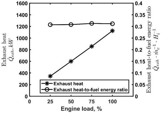
Figure 1.
Exhaust heat and exhaust heat-to-fuel energy ratio, , as a function of the engine load, 1500 rpm.
The exhaust heat is recovered by a RHX specifically designed for this purpose. A schematic representation of the internal combustion engine coupled with the RHX is reported in Figure 2. Heat sources such as coolant fluid, with temperatures in the range 80–90 °C, and lubricant, with temperatures between 80 and 120 °C, were not exploited. In fact, these temperatures being close to the ambient one, harnessing them is not economically convenient [38,39].
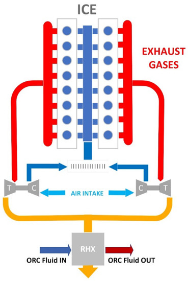
Figure 2.
Schematic representation of the internal combustion engine (ICE) coupled with the recovery heat exchanger (RHX).
2.2. ORC System Configurations
Three ORC system configurations were modeled in a Simulink® environment:
- Single-pressure, Figure 3a: It consists of a pump (P), an evaporator (RHX), a turbine (T), and a condenser (C).
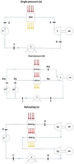 Figure 3. Representation of the ORC layouts considered for waste heat recovery: single-pressure (a), dual-pressure (b), and reheating (c).
 - Dual-pressure, Figure 3b: It consists of two evaporating pressure levels feeding the turbine. The flow coming from the low-pressure circuit enters the turbine at an intermediate expansion stage.
- Single-pressure with reheating, Figure 3c: It consists of an evaporator feeding the high-pressure turbine T1 and a reheater feeding the low-pressure turbine T2. The working fluid enters T2 in superheated conditions.
A regenerative cycle was not considered since, even if it increases the cycle efficiency, it reduces the power output, which, on the contrary, should be maximized in a recuperative ORC.
The Rankine cycle simulations are based on the following assumptions: steady-state conditions, adiabatic expanders and pumps, and head losses neglected in pipes. The expander efficiency is assumed to be 0.80 and pump efficiency 0.75, according to the data available in the literature [30,40].
The addition of a RHX on the exhaust line increases the back pressure and, consequently, the engine pumping work. However, the effect of the exhaust backpressure on the engine efficiency was neglected, the values between 0.8 and 3.2 kPa for R1233zd(e) and between 0.9 and 4.0 kPa for R601; the lowest pressure drops correspondingly to the single-pressure cycle and the highest to the dual-pressure cycles [22,41].
2.3. ORC Working Fluids
The selected working fluids are R1233zd(e) and n-pentane (R601). R1233zd(e) is an innovative working fluid belonging to the hydrofluoroolefins (HFO), developed for replacing flammable fluids and fluids with high ozone depletion potential (ODP) and global warming potential (GWP) in refrigerant applications. R1233zd has a flammability index equal to zero (0/4), with a health index of 2/4 and no reactivity hazards (0/4); it has a GWP equal to 1 and ODP index zero. R601 is a hydrocarbon with excellent thermodynamic properties as an ORC working fluid but with a flammability index of 4/4, a low health hazard (1/4), and no chemical reactivity (0/4); it does not have ODP, while the 100-years GWP is 5 [6,20]. Both R601 and R1233zd(e) belong to the to the dry fluid class. As R1233zd(e) is a recently developed fluid, its thermodynamic properties are not yet available in the main modeling code libraries. For this reason, correlations were used to obtain the thermophysical properties of the fluid using the data available in the literature [30,31].
The fluid thermal resistance depends also on the convective heat transfer coefficients, hext and hint. The first one is linked to the geometry of the RHX [42], while the second one is calculated using the Gnielinski correlation [41]. The RHX tubes were assumed to be stainless-steel-type 410, whose thermal conductivity is about 25 W/m/K, according to the ASTM AISI Standards.
The fluid properties were evaluated by using CoolProp [43], except for the thermal conductivity of R1233zd(e). The thermal conductivity of the liquid phase of R1233zd(e), expressed in W/m/K, was calculated according to the following equation [44]:
where pcrit is the critical pressure in bars, M is the molar mass in kg/kmol, Tr is the reduced temperature (dimensionless), and ω is the acentric factor (dimensionless).
The thermal conductivity of the saturated liquid λL,sat is well-approximated by the following correlation [45], with Tsat as the saturation temperature in K:
The thermal conductivity of the dry vapor λV,sat was determined according to:
The previous correlation can be modified to model the thermal conductivity of the fluid in superheated conditions when below the critical temperature, according to:
where pressure is expressed in bars, temperature in Kelvin, and thermal conductivity in W/mK.
For a superheated vapor over the critical temperature, the following correlation is proposed:
where pr is the reduced pressure [45].
2.4. Recovery Heat Exchanger (RHX) Model
A compact crossflow exchanger was considered to minimize the system size for an easy installation.
Heat exchanger tubes are finned to increase the heat transfer between the two fluids. Since there are no analytical expressions for the determination of the heat transfer coefficient hext and friction factor f, they were derived using the correlations based on the experimental data reported in [42] for circular tubes with circular fins, Surface CF-8.72.
The fluid properties were calculated using an average temperature between the inlet and outlet of RHX. The external fluid (the exhaust gases) was considered “mixed” and the internal one (the working fluid) “unmixed”.
The RHX was assumed to be composed of two parts in a series with only one passage of the fluid in the tubes, the preheater of length L1, and the evaporator of length L2 (Figure 4).
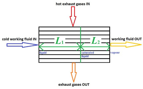
Figure 4.
RHX schematic representation showing the preheater, L1, and the evaporator, L2.
The pressurized cold working fluid enters the preheater of the RHX as liquid and is heated until reaching a saturated liquid state. Pt1 is the heat exchanged in the preheater of the RHX:
where cp is the specific heat at a constant pressure, h is the specific enthalpy, ṁ the mass flow rate, P is the power, T is the temperature, and the subscript sl refers to the saturated liquid state for the ORC fluid. The specific heat is evaluated at the average temperature of the hot gases.
Afterwards, the preheated ORC fluid enters the evaporator, where it is assumed to attain the thermodynamic state of dry saturated vapor. The heat exchanged Pt2 is:
where subscript 2 indicates the vaporizer.
Assuming a uniform temperature for each fluid in every cross-section along the flow direction and uniform mass distribution of the external fluid along the length of the RHX tubes, the following equation can be written for a one-pass heat exchanger:
where L is the length in m.
The ε-NTU method provides the overall thermal conductance UA1 and UA2 for the preheater and the evaporator to reach the desired working fluid thermodynamic conditions for each part of the heat exchanger [46].
where i = 1 (preheater) or 2 (vaporizer), A is the heat transfer area in m2, Ċ is the thermal capacity per unit time, NTU is the number of heat transfer units, U is the overall heat transfer coefficient, UA is the overall thermal conductance, and ε is the heat exchanger effectiveness.
The overall thermal conductance can be calculated according to:
where R is the thermal resistance, and ext indicates the external fluid, int the internal fluid, and mat the RHX tubes.
Each thermal resistance and the overall conductance are functions of the RHX tube lengths. Once the number of rows and the number of tubes per row are defined, the lengths of the tubes must be iteratively changed to verify the following equation:
Once UA1 is calculated, it is also known as the total length of the RHX, L1 + L2 and, consequently, L1 and L2 are related to the total length.
Depending on the working fluid characteristics, the expansion of a dry saturated vapor in a turbine can cause fluid condensation. This can be avoided by adding a superheater to change the working fluid exiting the RHX to a superheated vapor.
Having designed the RHX preheater and evaporator for operating with a defined mass flow rate, ṁc must be reduced until the desired temperature as the superheater outlet is attained.
For the reheater, the designing process is simpler, because there is no phase change, and the RHX can be considered as a single unit. The length of the reheater is calculated, imposing equality between UAi and UAi,required.
2.5. Exergy Analysis
The exergy analysis was accomplished considering the ambient state at T0 = 298 K and p0 = 101.3 kPa. The standard air composition was assumed for the dead state. Furthermore, since the exhaust gases enter and exit the RHX components without changing their chemical composition, and the same is true for the ORC fluids, only the physical exergy component was considered in the calculations. The exhaust gases are considered as a mixture of ideal gases, with molar compositions equal to 6.6% for CO2, 7.0% for H2O, 76.2% for N2, and 10.2% for O2, corresponding to an equivalence ratio ф equal to 0.5, typical of the employed engine. The exhaust gas composition changes with the engine load due to the variation of ф, but this occurrence was not considered, because it does not cause a significant variation in the thermodynamic properties of the exhaust stream.
The exergy efficiency of the ORC system was evaluated as:
With PORC, the net mechanical exergy of the cycle and the terms at the denominator represent the exhaust gas physical exergy variations.
3. Results and Discussion
3.1. RHX Data
The thermodynamic data of the cycle are obtained from the results of the RHX design, as indicated in the previous section.
It should be observed that, for any ORC configuration, R1233zd(e), Table 2a, allows a larger total heat transfer between the two fluids compared with R601, Table 2b. The dual-pressure cycle shows the largest heat transfer. In fact, the high-pressure section is identical to those of the single-pressure and reheating cycles, but there is the low-pressure section, where more ORC working fluid flow receives additional heat from the exhaust gas. For the reheating configuration, the same ORC mass flow rate goes through first in the high-pressure RHX, then, after a first expansion, is heated again by the exhausts in the low-pressure heat exchanger. Using these main heat transfer data from the RHX component design, the different cycles were modeled, and the results are presented in the next section.

Table 2.
Total recovered heat for different ORC configurations: (a) R1233zd(e) and (b) R601.
3.2. Rankine Cycle Thermodynamic Model
For both fluids, the Rankine cycles operate between the pressure levels reported in Table 3, which also shows the maximum cycle temperature. The condensation pressure of 0.3 MPa for R1233zd(e) and 0.15 MPa for R601 assures a saturation temperature of 324 K and 321 K for R1233zd(e) and R601, respectively, values compatible with the environmental temperature. The maximum pressure is set to 3.0 MPa for both fluids to avoid material strength issues [22] and to stay below the critical pressures. The maximum temperatures guarantee a superheated fluid at the expander inlet.

Table 3.
Maximum ORC cycle pressure and intermediate pressure (dual-pressure cycle only) for R1233zd(e) and R601.
Figure 5, Figure 6 and Figure 7 report the temperature–entropy charts for the single-pressure, dual-pressure, and reheating cycles, respectively: (a) R1233zd(e) and (b) R601. The cycle is assumed to not change with the engine load and, therefore, with the recovered heat , Table 2, because the ORC working fluid mass flow rates were adjusted to achieve the same degree of superheating, as the available exhaust heat varies.
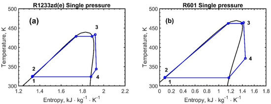
Figure 5.
Temperature–entropy chart for the single-pressure ORC configuration: (a) R1233zd(e) and (b) R601. The numbers in the figures represent the thermodynamic states of the fluids.
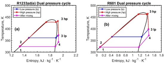
Figure 6.
Temperature–entropy chart for the dual-pressure ORC configuration: (a) R1233zd(e) and (b) R601. The numbers in the figures represent the thermodynamic states of the fluids.
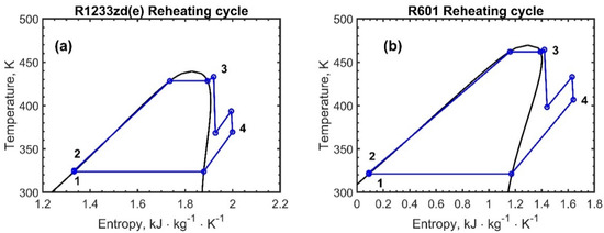
Figure 7.
Temperature–entropy chart for the reheating the ORC configurations: (a) R1233zd(e) and (b) R601. The numbers in the figures represent the thermodynamic states of the fluids.
The high-pressure section is the same for any configuration, processing the same mass flow rate for each fluid, with differences only in the design of the low-pressure exchanger for the dual-pressure and the reheating cycle configurations. The working fluid mass flow rates are reported in Table 4, where is the total mass flow rate for the simple and reheating cycles and that of the working fluid of the high-pressure section of the dual-pressure cycles, while is the low-pressure section mass flow rate for the dual-pressure cycles. As the engine load and increase, it is possible to process a higher working fluid mass flow rate, keeping a constant degree of superheating.

Table 4.
Working fluid mass flow rate for the high-pressure and low-pressure circuits.
The results of the ORC simulations are proposed in this section for the considered system configurations and the two fluids: R1322zd(E) and R601. The ORC power output depends on the cycle efficiency and recovered heat according to the equation:
is affected by the ORC system configuration, as previously reported in Table 2, and in Figure 8, refers to the fuel energy. Compared with single-pressure, the reheating and dual-pressure cycles allow to recover a higher amount of heat, with the latter showing the highest values, and these values are slightly affected by the engine load. In fact, considering R1233zd(e), the ratio for the single-pressure configuration is almost constant with the engine load and equal to 0.180, whereas, for the reheating and dual-pressure, a slight increase with the engine load is observed, from 0.198 to 0.206 and from 0.210 to 0.232, respectively. A comparable occurrence is displayed for the R601 fluid.
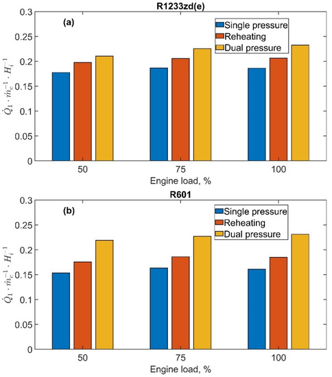
Figure 8.
Recovered exhaust heat-to-fuel energy ratio, , as a function of the engine load at 1500 rpm: (a) R1233zd(e) and (b) R601.
The ORC thermodynamic efficiency is shown in Figure 9a,b for R1233zd(e) and R601, respectively. The efficiency of the ORC plant is nearly constant with the engine load for a defined ORC layout. This is due to the constant maximum cycle pressure and temperature values, the last of which was achieved by optimizing the working fluid mass flow rate. In fact, the Rankine cycle was kept unchanged with the engine load, i.e., different exhaust gas mass flow rate and temperature, adjusting the Rankine cycle working fluid mass flow rate to attain the target temperature at the RHX outlet. In this case, it can be observed that the single-pressure cycle shows the highest efficiency with values of 16.0% for R1233zd(e) and 18.2% for R601. In fact, reheating and low pressure circuits in the case of dual-pressure both operate at a lower pressure level, constrained by the exhaust gas temperature value at the outlet of the first heat exchanger. The amount of heat recovered in the low-pressure circuit is transferred to the working fluid at a lower average temperature, and consequently, the thermodynamic efficiency slightly decreases. Though this can appear as a negative result, it should be considered that, in ORC systems, where the heat is recovered and not produced by the combustion of a fuel, the focus is mainly on the ORC power output compared to on the system efficiency.
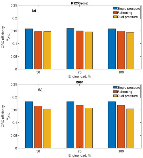
Figure 9.
ORC efficiency as a function of the engine load for both fluids and for all ORC configurations: (a) R1233zd(e) and (b) R601.
The results shown in Figure 10 display the PORC/Peng ratio as a function of the engine load, PORC as the ORC net power output and Peng the engine power output. For both fluids: R1233zd(e), Figure 10a, and R601, Figure 10b, the engine load again does not significantly affect the contribution of the ORC system to the total produced power output. In fact, as previously observed in Figure 8 and Figure 9, neither the exchanged heat or the efficiency depend on the engine load. Therefore, PORC/Peng is constant at all engine loads. Conversely, the ORC configuration plays an important role, with the dual-pressure cycle allowed to recover the highest power fraction at all engine loads for both fluids, with a maximum of around 8.0% for R1233zd(e) and 8.7% for R601. For the dual-pressure cycle, in fact, the higher recovered heat offsets the reduction of the cycle efficiency.
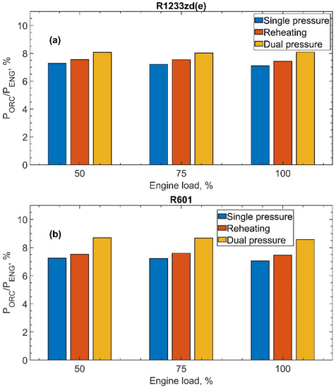
Figure 10.
Relative contribution of the ORC power, PORC, related to the engine power Peng as a function of the engine load for both fluids and for all ORC configurations: (a) R1233zd(e) and (b) R601.
Figure 11a,b plot the exergy efficiency of the ORC plant, unveiling the amount of recoverable work from the exhaust gas stream exergy content. The values of the exergy efficiency are always larger than 30% for both the fluids and all cycle configurations, with the highest values obtained with the single-pressure cycle. Comparing the two fluids, some important differences can be observed. R601 shows a better exergy performance, always overcoming the innovative R1223zd(e) fluid. For the single-pressure case, R601 presents values 10% greater than R1223zd(e), ranging from 0.38 to 0.36 as the engine load increases from 50% to 100%, while R1223zd(e) underperforms in the range 0.34–0.33 for the same engine load variation. The differences between the two fluids are lower considering the reheating and dual-pressure cycles, with deviations in the range 4.0–7.5%.
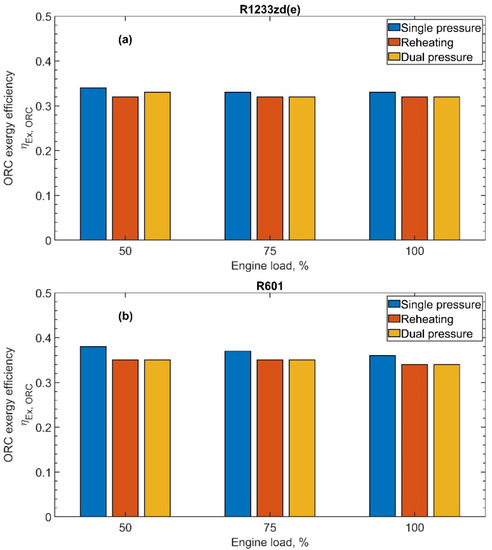
Figure 11.
ORC exergy efficiency as a function of the engine load for all ORC configurations: (a) R1233zd(e) and (b) R601.
The increase of the engine load brings about an increment of the exhaust gas temperature at the RHX outlet, thus with a larger physical exergy content that could be conveniently exploited. All the cycle configurations show a typical behavior relating the exergy efficiency with the exhaust gas outlet temperature from the RHX; in fact, the larger the gas outlet temperature, the lower the exergy efficiency of the ORC plant.
The dual-pressure ORC configuration is the most effective solution in recovering the exhaust heat from the internal combustion engine, with a consequent maximum ORC power generation. This implies that, when possible, a dual-pressure heat exchanger should be integrated in the exhaust line.
R1233zd(e) is a new fluid that gives promising thermodynamic results as the working fluid in ORC systems. Furthermore, it gives no flammability concerns and has a low ozone depletion potential and global warming potential. The thermodynamic performances are comparable with those obtained with the reference working fluid R601, which can be considered a benchmark.
4. Conclusions
This paper investigates the use of an innovative working fluid, R1233zd(e), for recovering the exhaust heat from an internal combustion engine for marine application in an ORC. R1233zd(e) is a new fluid belonging to the hydrofluoroolefins, developed for replacing flammable fluids and fluids with high ozone depletion potential and global warming potential in refrigerant applications. The performance of the system with R1233zd(e) is then compared with R601, a hydrocarbon with excellent thermodynamic properties but with flammability concerns.
The performance assessment was carried out with different system configurations: a simple cycle, a reheating cycle, and a dual-pressure cycle.
The results show that the recovered heat can be efficiently exploited using all the investigated ORC configurations, with the dual-pressure configuration performing the highest exploitation of exhaust heat. Consequently, despite the additional heat recovered in the low-pressure section causing a reduction of the Rankine cycle thermodynamic efficiency, it is possible to produce up to 8.0% more mechanical power with R1233zd(e) in the dual-pressure configuration. This result is comparable with what can be obtained with R601 at the same operating conditions, where the relative contribution of the ORC power related to the engine power is 8.7%.
Exergy efficiency comparisons were also carried out, observing that R601 outperformed R1223zd(e), especially for the single-pressure level with a difference of about 10%, whereas the other configurations displayed lower differences, between 4.0 and 7.5%.
In conclusion, the innovative R12233zd(e) can be adopted as the ORC working fluid with a thermodynamic performance comparable with the reference fluid R601 but with lower flammability risks and, in general, a lower environmental impact.
Future research will be focused on exploring the use of ORC bottoming larger internal combustion engines for ship propulsion, adopting different working fluids and performing an economic analysis of the proposed solutions.
Author Contributions
Conceptualization, A.M., B.M. and A.U.; Data curation, A.M. and D.L.; Investigation, A.M., D.L., M.V.P. and A.U.; Methodology, A.M.; Resources, M.V.P.; Software, D.L.; Supervision, B.M., M.V.P. and A.U.; Validation, B.M. and D.L.; Writing—original draft, A.M.; Writing—review & editing, B.M. and A.U. All authors have read and agreed to the published version of the manuscript.
Funding
This research received no external funding.
Conflicts of Interest
The authors declare no conflict of interest.
Nomenclature
| Symbols | |
| A | Heat transfer area (m2) |
| Ċ | Thermal capacity (W/K) |
| cp | Specific heat (J/(kg∙K)) |
| f | Friction factor (-) |
| h | Specific enthalpy (J/kg) |
| ṁ | Mass flow rate (kg/s) |
| L | Length (m) |
| M | Molar mass (kg/kmol) |
| NTU | Number of heat transfer unit (-) |
| P | Power (kW) |
| p | Pressure (Pa) |
| pr | Reduced pressure (-) |
| Heat (kW) | |
| R | Thermal resistance (m2K/W) |
| RHX | Recovery Heat Exchanger |
| T | Temperature (K) |
| Tr | Reduced temperature (-) |
| U | Overall heat transfer coefficient (W/(m2∙K)) |
| UA | Overall thermal conductance (W/K) |
| Greek symbols | |
| ε | Heat exchanger effectiveness |
| η | Efficiency (-) |
| λ | Thermal conductivity (W/(m∙K)) |
| ω | Acentric factor (-) |
| ф | Equivalence ratio (-) |
| Subscripts | |
| 1 | Preheater |
| 2 | Vaporizer |
| ORC | Organic Rankine Cycle |
| crit | Critical |
| exh | Exhaust gas |
| EX | Exergy |
| ext | External fluid |
| i | 1 (preheater) or 2 (vaporizer) |
| in | Inlet |
| int | Internal fluid |
| L | Liquid |
| mat | Material of the tubes |
| max | Maximum |
| min | Minimum |
| out | Outlet |
| sat | Saturated |
| sl | Saturated liquid |
| t | Thermal |
| V | Vapor |
References
- Nondy, J.; Gogoi, T.K. Exergoeconomic Investigation and Multi-Objective Optimization of Different ORC Configurations for Waste Heat Recovery: A Comparative Study. Energy Convers. Manag. 2021, 245, 114593. [Google Scholar] [CrossRef]
- United Nations. Kyoto Protocol to the United Nations Framework Convention on Climate Change. Available online: https://unfccc.int/resource/docs/convkp/kpeng.pdf (accessed on 21 October 2021).
- IMO. IMO—The International Maritime Organization. Available online: https://www.imo.org/en (accessed on 21 October 2021).
- Fourth IMO GHG Study 2020 Full Report; International Maritime Organization: London, UK, 2020.
- The European Parliament; The Council of the European Union. Directive 2012/33/EU Regards the Sulphur Content of Marine Fuels. Off. J. Eur. Union 2012, 1–13. [Google Scholar]
- EPA. Control of Emissions from New and In-Use Marine Compression-Ignition Engines and Vessels; United States Environmental Protection Agency: Washington, DC, USA, 2018.
- EPA. Control of NOx, SOx, and PM Emissions from Marine Engines and Vessels Subject to the Marpol Protocol; United States Environmental Protection Agency: Washington, DC, USA, 2008.
- IMO. Reduction of GHG Emissions from Ships; International Maritime Organization: London, UK, 2021. [Google Scholar]
- Ni, P.; Wang, X.; Li, H. A Review on Regulations, Current Status, Effects and Reduction Strategies of Emissions for Marine Diesel Engines. Fuel 2020, 279, 118477. [Google Scholar] [CrossRef]
- Boscarato, I.; Hickey, N.; Kašpar, J.; Prati, M.V.; Mariani, A. Green Shipping: Marine Engine Pollution Abatement Using a Combined Catalyst/Seawater Scrubber System. 1. Effect of Catalyst. J. Catal. 2015, 328, 248–257. [Google Scholar] [CrossRef]
- Cao, J.; Li, T.; Zhou, X. A Study of Smart Thermal Insulation Coating on Improving Thermal Efficiency in a Marine Two-Stroke Low-Speed Diesel Engine. Fuel 2021, 304, 120760. [Google Scholar] [CrossRef]
- Dere, C.; Deniz, C. Effect Analysis on Energy Efficiency Enhancement of Controlled Cylinder Liner Temperatures in Marine Diesel Engines with Model Based Approach. Energy Convers. Manag. 2020, 220, 113015. [Google Scholar] [CrossRef]
- Heywood, J.B. Internal Combustion Engine Fundamentals, 2nd ed.; Mc Graw-Hill: New York, NY, USA, 2018. [Google Scholar]
- Alshammari, F.; Pesyridis, A.; Alshammari, A.S.; Alghafis, A.; Alatawi, I.; Alzamil, A. Potential of Capturing Transportation Wasted Heat for Better Fuel Economy and Electricity Generation: Comprehensive Testing Organic Rankine Cycle. Energy Convers. Manag. 2022, 267, 115939. [Google Scholar] [CrossRef]
- Lion, S.; Michos, C.N.; Vlaskos, I.; Rouaud, C.; Taccani, R. A Review of Waste Heat Recovery and Organic Rankine Cycles (ORC) in on-off Highway Vehicle Heavy Duty Diesel Engine Applications. Renew. Sustain. Energy Rev. 2017, 79, 691–708. [Google Scholar] [CrossRef]
- Lion, S.; Michos, C.N.; Vlaskos, I.; Taccani, R. A Thermodynamic Feasibility Study of an Organic Rankine Cycle (ORC) for Heavy-Duty Diesel Engine Waste Heat Recovery in off-Highway Applications. Int. J. Energy Environ. Eng. 2017, 8, 81–98. [Google Scholar] [CrossRef]
- Xu, B.; Rathod, D.; Yebi, A.; Filipi, Z. A Comparative Analysis of Real-Time Power Optimization for Organic Rankine Cycle Waste Heat Recovery Systems. Appl. Therm. Eng. 2020, 164, 114442. [Google Scholar] [CrossRef]
- Nazari, N.; Heidarnejad, P.; Porkhial, S. Multi-Objective Optimization of a Combined Steam-Organic Rankine Cycle Based on Exergy and Exergo-Economic Analysis for Waste Heat Recovery Application. Energy Convers. Manag. 2016, 127, 366–379. [Google Scholar] [CrossRef]
- Valencia, G.; Fontalvo, A.; Cárdenas, Y.; Duarte, J.; Isaza, C. Energy and Exergy Analysis of Different Exhaust Waste Heat Recovery Systems for Natural Gas Engine Based on ORC. Energies 2019, 12, 2378. [Google Scholar] [CrossRef]
- Valencia, G.; Fontalvo, A.; Duarte Forero, J. Optimization of Waste Heat Recovery in Internal Combustion Engine Using a Dual-Loop Organic Rankine Cycle: Thermo-Economic and Environmental Footprint Analysis. Appl. Therm. Eng. 2021, 182, 116109. [Google Scholar] [CrossRef]
- Wu, X.; Zhang, N.; Xie, L.; Ci, W.; Chen, J.; Lu, S. Thermoeconomic Optimization Design of the ORC System Installed on a Light-Duty Vehicle for Waste Heat Recovery from Exhaust Heat. Energies 2022, 15, 4486. [Google Scholar] [CrossRef]
- Michos, C.N.; Lion, S.; Vlaskos, I.; Taccani, R. Analysis of the Backpressure Effect of an Organic Rankine Cycle (ORC) Evaporator on the Exhaust Line of a Turbocharged Heavy Duty Diesel Power Generator for Marine Applications. Energy Convers. Manag. 2017, 132, 347–360. [Google Scholar] [CrossRef]
- Wang, E.H.; Zhang, H.G.; Fan, B.Y.; Ouyang, M.G.; Zhao, Y.; Mu, Q.H. Study of Working Fluid Selection of Organic Rankine Cycle (ORC) for Engine Waste Heat Recovery. Energy 2011, 36, 3406–3418. [Google Scholar] [CrossRef]
- Bao, J.; Zhao, L. A Review of Working Fluid and Expander Selections for Organic Rankine Cycle. Renew. Sustain. Energy Rev. 2013, 24, 325–342. [Google Scholar] [CrossRef]
- Xu, W.; Zhao, L.; Mao, S.S.; Deng, S. Towards Novel Low Temperature Thermodynamic Cycle: A Critical Review Originated from Organic Rankine Cycle. Appl. Energy 2020, 270, 115186. [Google Scholar] [CrossRef]
- Chen, H.; Goswami, D.Y.; Stefanakos, E.K. A Review of Thermodynamic Cycles and Working Fluids for the Conversion of Low-Grade Heat. Renew. Sustain. Energy Rev. 2010, 14, 3059–3067. [Google Scholar] [CrossRef]
- Méndez-Cruz, L.E.; Gutiérrez-Limón, M.Á.; Lugo-Méndez, H.; Lugo-Leyte, R.; Lopez-Arenas, T.; Sales-Cruz, M. Comparative Thermodynamic Analysis of the Performance of an Organic Rankine Cycle Using Different Working Fluids. Energies 2022, 15, 2588. [Google Scholar] [CrossRef]
- NFPA. Available online: https://www.nfpa.org/ (accessed on 3 October 2022).
- EPA. Greenhouse Gas Emissions. Available online: https://www.epa.gov/ghgemissions/understanding-global-warming-potentials (accessed on 3 August 2022).
- Wang, S.; Liu, C.; Zhang, S.; Li, Q.; Huo, E. Multi-Objective Optimization and Fluid Selection of Organic Rankine Cycle (ORC) System Based on Economic-Environmental-Sustainable Analysis. Energy Convers. Manag. 2022, 254, 115238. [Google Scholar] [CrossRef]
- Lion, S.; Vlaskos, I.; Rouaud, C.; Taccani, R. Overview of the Activities on Heavy Duty Diesel Engines Waste Heat Recovery with Organic Rankine Cycles (ORC) in the Frame of the ECCO-MATE EU FP7 Project. Energy Procedia 2017, 129, 786–793. [Google Scholar] [CrossRef]
- Hountalas, D.T.; Mavropoulos, G.C.; Katsanos, C.; Knecht, W. Improvement of Bottoming Cycle Efficiency and Heat Rejection for HD Truck Applications by Utilization of EGR and CAC Heat. Energy Convers. Manag. 2012, 53, 19–32. [Google Scholar] [CrossRef]
- Mariani, A.; Laiso, D.; Morrone, B.; Unich, A. Exergy Analysis of Organic Rankine Cycles with Zeotropic Working Fluids. Fluid Dyn. Mater. Process. 2023, 19, 593–601. [Google Scholar] [CrossRef]
- Chys, M.; van den Broek, M.; Vanslambrouck, B.; De Paepe, M. Potential of Zeotropic Mixtures as Working Fluids in Organic Rankine Cycles. Energy 2012, 44, 623–632. [Google Scholar] [CrossRef]
- Braimakis, K.; Karellas, S. Exergy Efficiency Potential of Dual-Phase Expansion Trilateral and Partial Evaporation ORC with Zeotropic Mixtures. Energy 2022, 262, 125475. [Google Scholar] [CrossRef]
- Scaccabarozzi, R.; Tavano, M.; Invernizzi, C.M.; Martelli, E. Thermodynamic Optimization of Heat Recovery ORCs for Heavy Duty Internal Combustion Engine: Pure Fluids vs. Zeotropic Mixtures. Energy Procedia 2017, 129, 168–175. [Google Scholar] [CrossRef]
- Enayatollahi, H.; Fussey, P.; Nguyen, B.K. Control of Organic Rankine Cycle, a Neuro-Fuzzy Approach. Control Eng. Pract. 2021, 109, 104728. [Google Scholar] [CrossRef]
- Mondejar, M.E.; Andreasen, J.G.; Pierobon, L.; Larsen, U.; Thern, M.; Haglind, F. A Review of the Use of Organic Rankine Cycle Power Systems for Maritime Applications. Renew. Sustain. Energy Rev. 2018, 91, 126–151. [Google Scholar] [CrossRef]
- Singh, D.V.; Pedersen, E. A Review of Waste Heat Recovery Technologies for Maritime Applications. Energy Convers. Manag. 2016, 111, 315–328. [Google Scholar] [CrossRef]
- Han, Z.; Li, P.; Han, X.; Mei, Z.; Wang, Z. Thermo-Economic Performance Analysis of a Regenerative Superheating Organic Rankine Cycle for Waste Heat Recovery. Energies 2017, 10, 1593. [Google Scholar] [CrossRef]
- Katsanos, C.O.; Hountalas, D.T.; Pariotis, E.G. Thermodynamic Analysis of a Rankine Cycle Applied on a Diesel Truck Engine Using Steam and Organic Medium. Energy Convers. Manag. 2012, 60, 68–76. [Google Scholar] [CrossRef]
- Kays, W.M.; London, A.L. Compact Heat Exchangers, 3rd ed.; MCGraw-Hill: New York, NY, USA, 1984. [Google Scholar]
- Bell, I.H.; Wronski, J.; Quoilin, S.; Lemort, V. Pure and Pseudo-Pure Fluid Thermophysical Property Evaluation and the Open-Source Thermophysical Property Library Coolprop. Ind. Eng. Chem. Res. 2014, 53, 2498–2508. [Google Scholar] [CrossRef] [PubMed]
- Tomassetti, S.; Coccia, G.; Pierantozzi, M.; Di Nicola, G. Correlations for Liquid Thermal Conductivity of Low GWP Refrigerants in the Reduced Temperature Range 0.4 to 0.9 from Saturation Line to 70 MPa. Int. J. Refrig. 2020, 117, 358–368. [Google Scholar] [CrossRef]
- Alam, M.J.; Islam, M.A.; Kariya, K.; Miyara, A. Measurement of Thermal Conductivity and Correlations at Saturated State of Refrigerant Trans-1-chloro-3,3,3-Trifluoropropene (R-1233zd(E)). Int. J. Refrig. 2018, 90, 174–180. [Google Scholar] [CrossRef]
- Hesselgreaves, J.E. Compact Heat Exchangers; Pergamon: Oxford, UK, 2001. [Google Scholar] [CrossRef]
Publisher’s Note: MDPI stays neutral with regard to jurisdictional claims in published maps and institutional affiliations. |
© 2022 by the authors. Licensee MDPI, Basel, Switzerland. This article is an open access article distributed under the terms and conditions of the Creative Commons Attribution (CC BY) license (https://creativecommons.org/licenses/by/4.0/).