
Numerical and Experimental Study of a Novel Additively Manufactured Metal-Polymer Composite Heat-Exchanger for Liquid Cooling Electronics


Abstract
:1. Introduction
2. Experimental Study
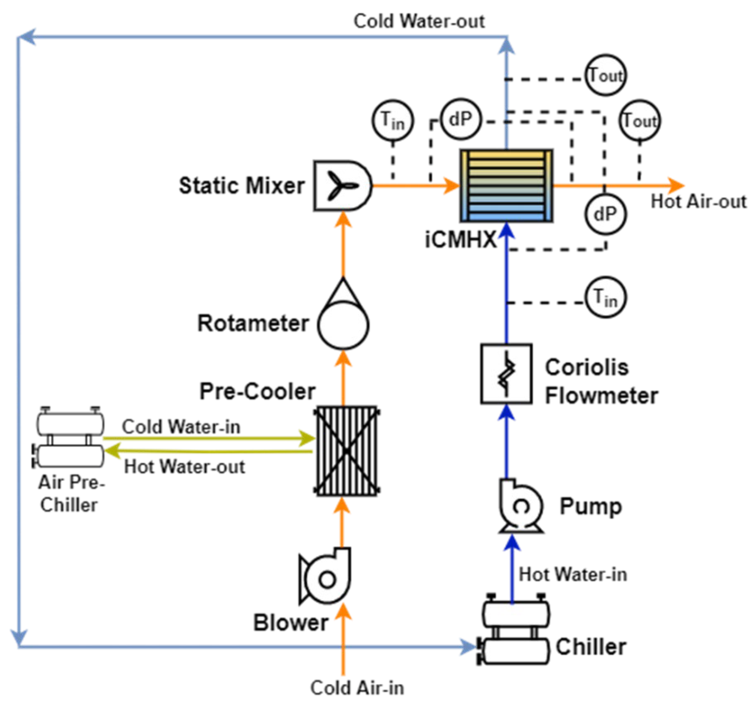
2.1. Test Setup
2.2. Instrumentation
2.3. Data Reduction
2.4. Uncertainty Analysis
3. Effect of Printing Variabilities
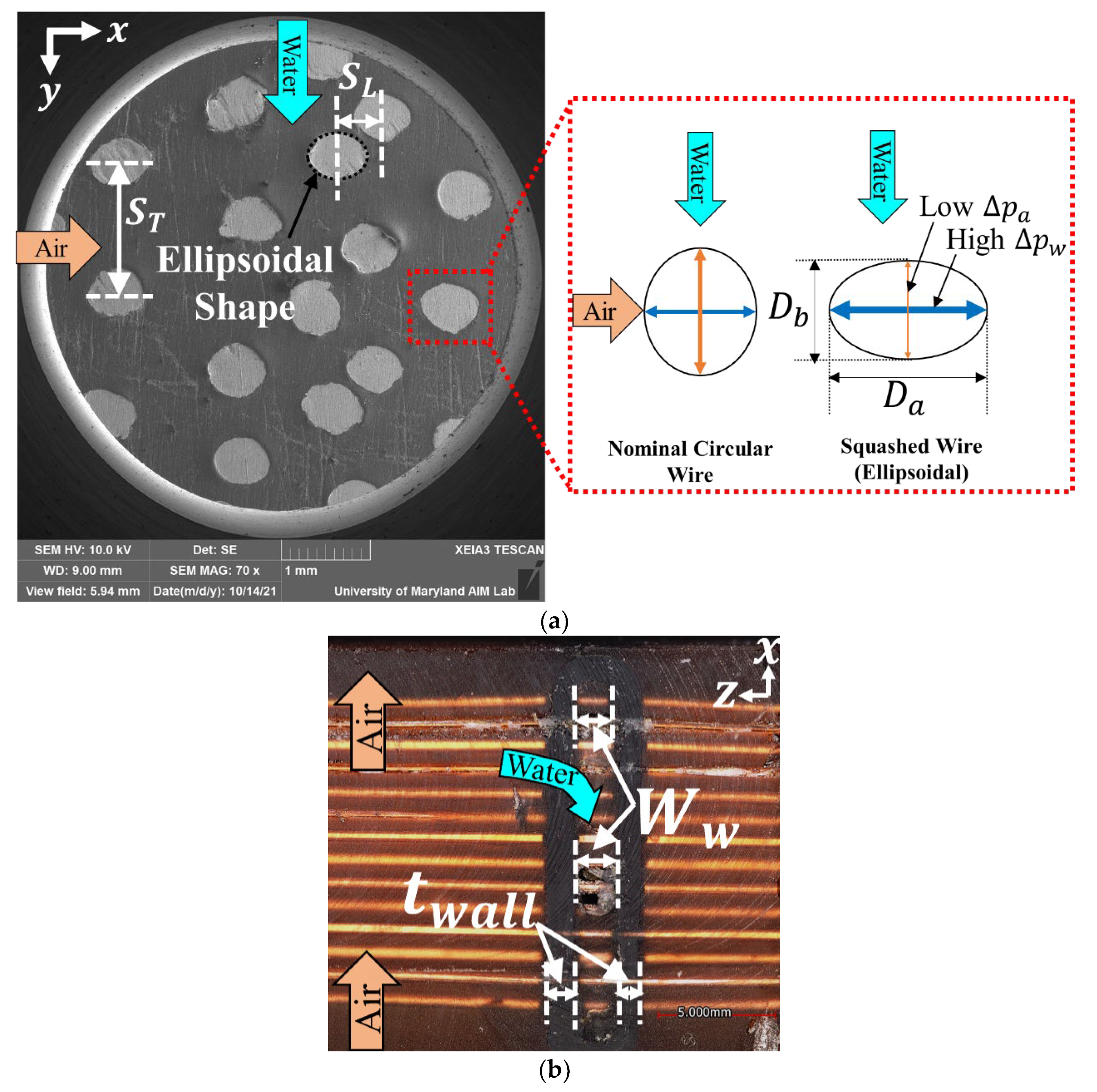
- The wires were extremely squashed in the water flow direction (y axis), such that they acquired spatially varying ellipsoidal shapes instead of nominal circular shapes (see Figure 4a). This could be due to improper functioning of the wire-extruder mechanism of the printer’s metal head.
- The wire spacings, particularly SL, varied with a high standard deviation, which is evident in Figure 4a. This misalignment among a few rows of wires deviated from the nominal staggered configuration and might have occurred due to precision errors in the movement of the printer’s metal head.
- Water channel width, Ww, also varied spatially due to variable polymer wall thickness (see Figure 4b), which is possibly caused by precision errors in the movement of the printer’s polymer head. The deviation in the average reading of the width of the water channel from its nominal reading was the highest of all geometrical parameters.
- The coating thickness of polyurethane sealant (tcoat) around the wire was measured to be around 20
4. Numerical Study
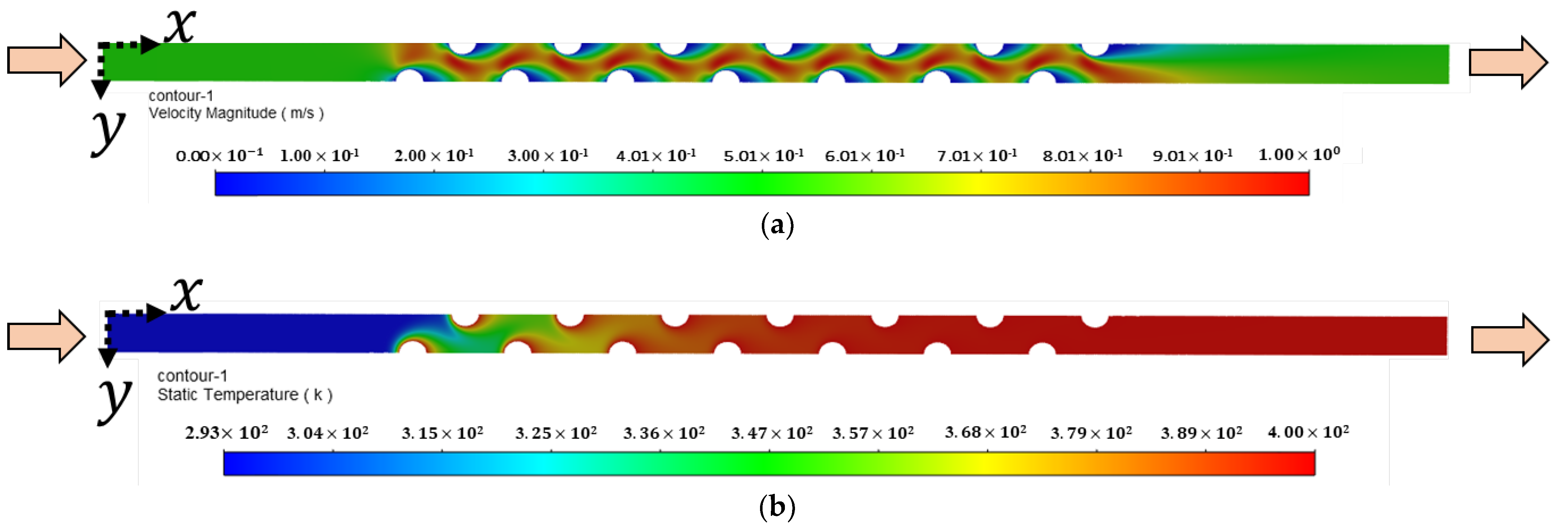
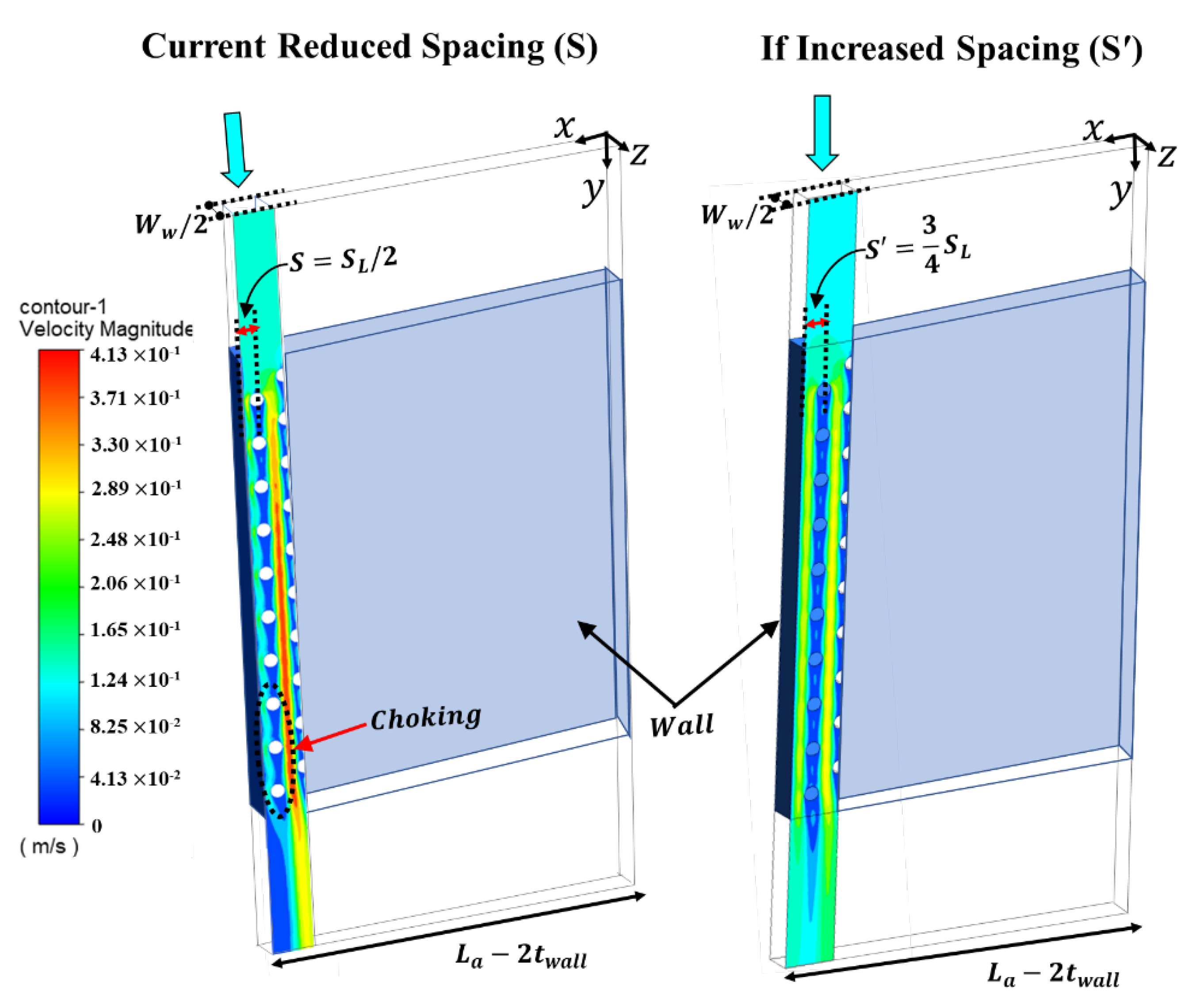
4.1. 3D CFD Model
4.2. Analytical Model for the Entire HX
5. Results and Discussion
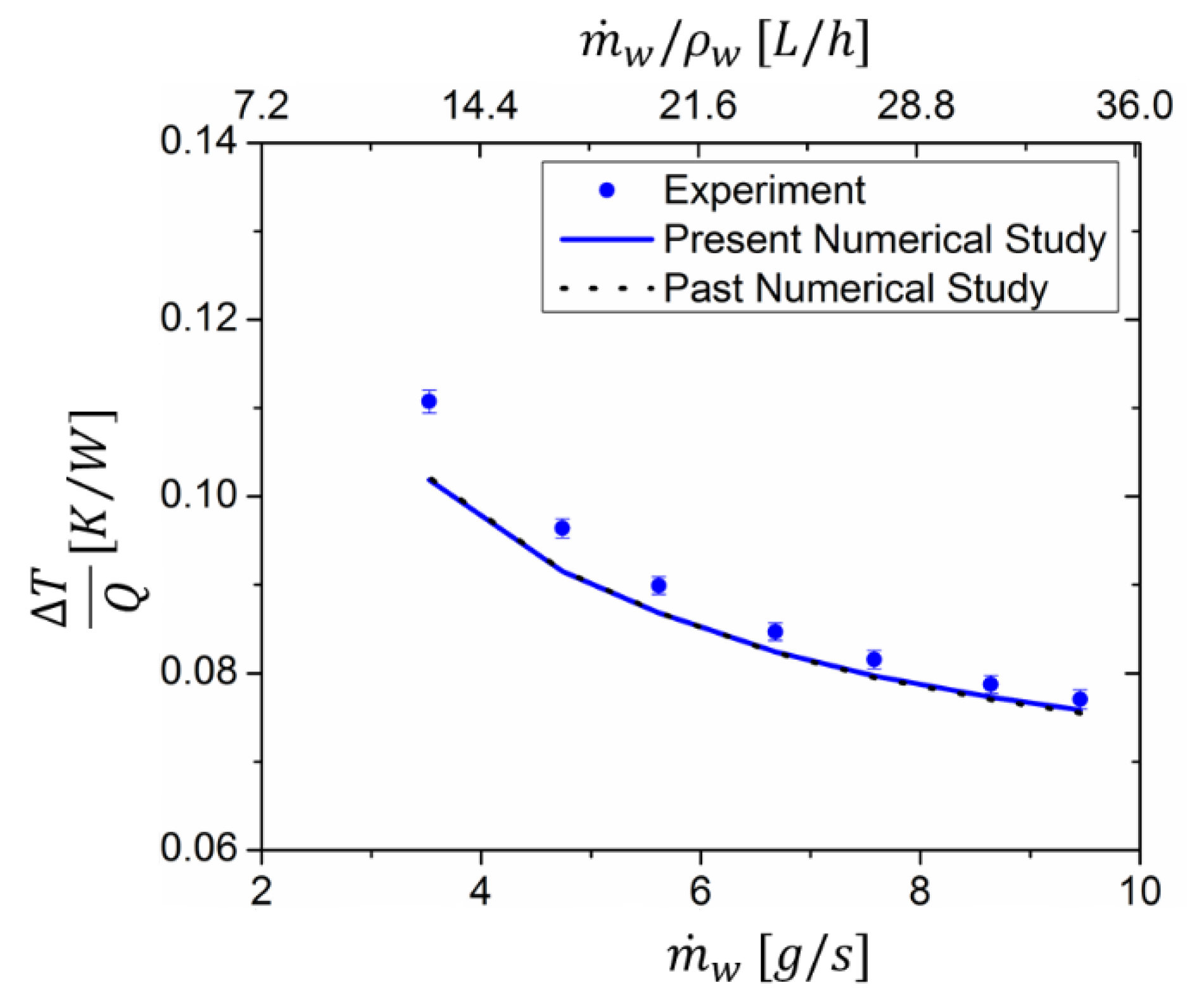
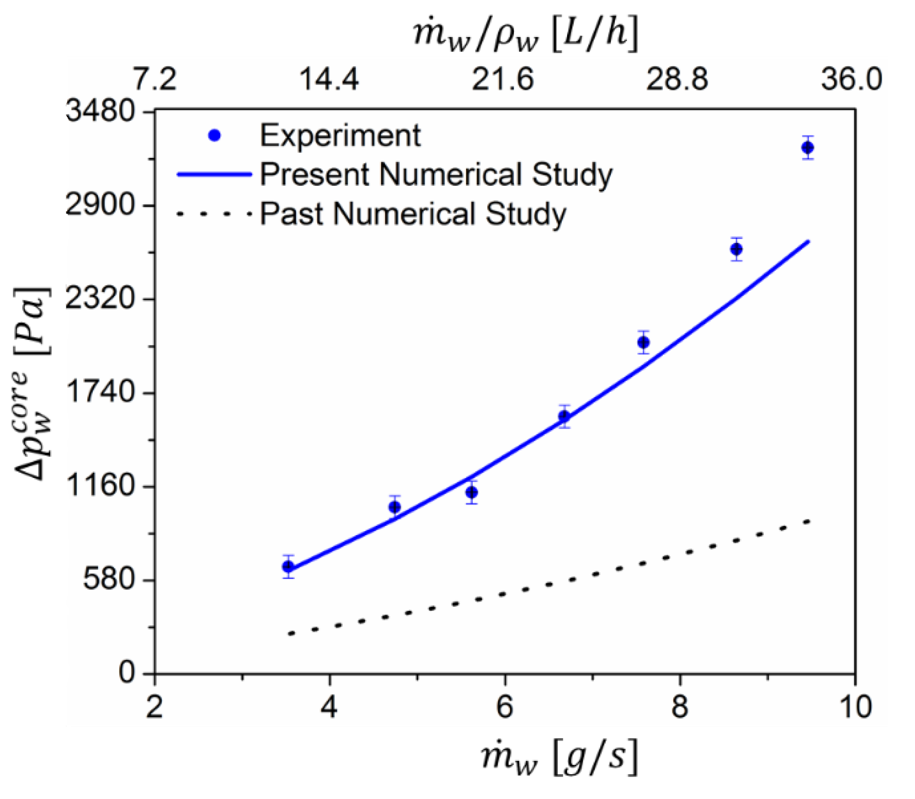
5.1. Validation of Numerical Results with Water-Side Testing Data
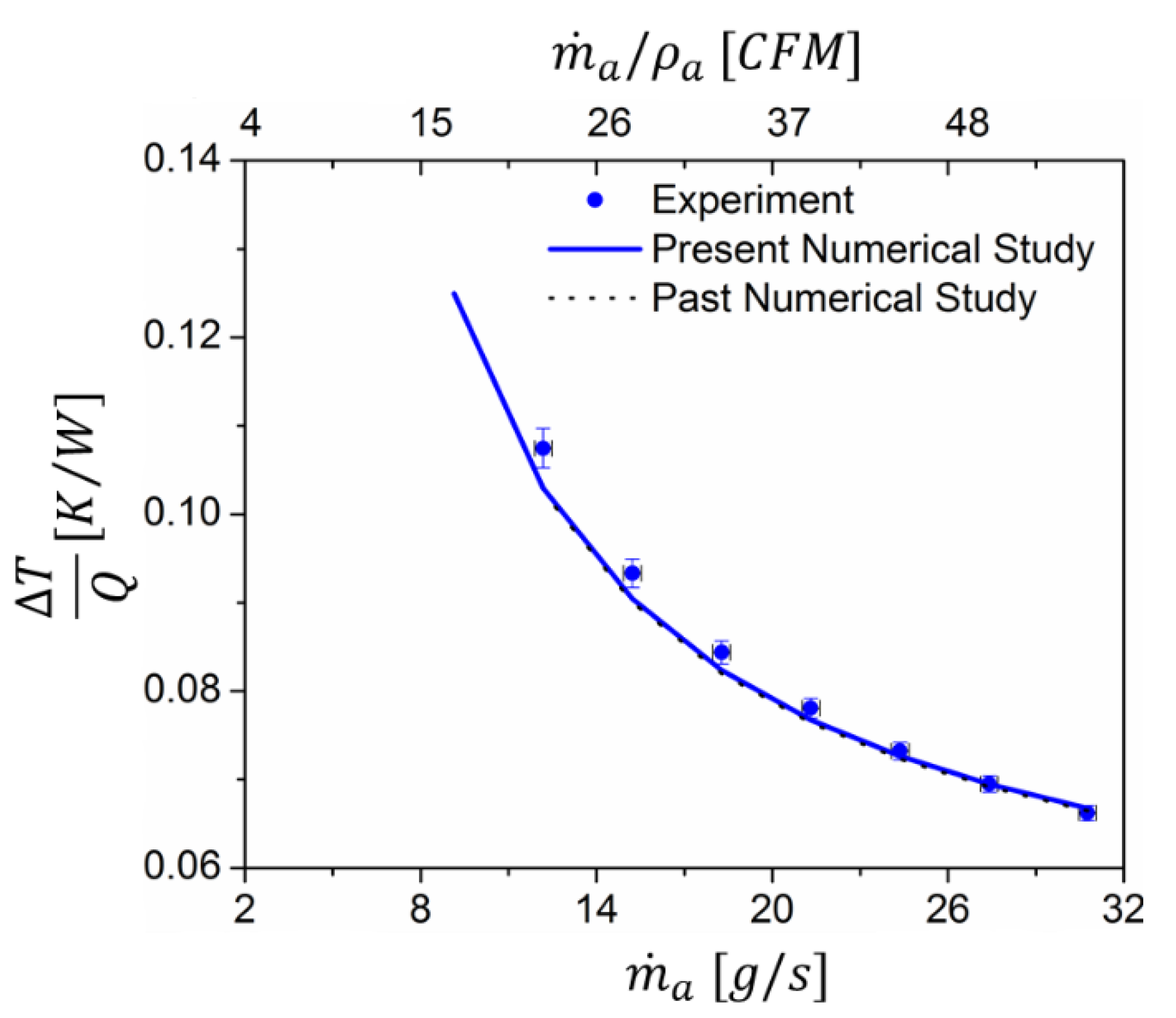
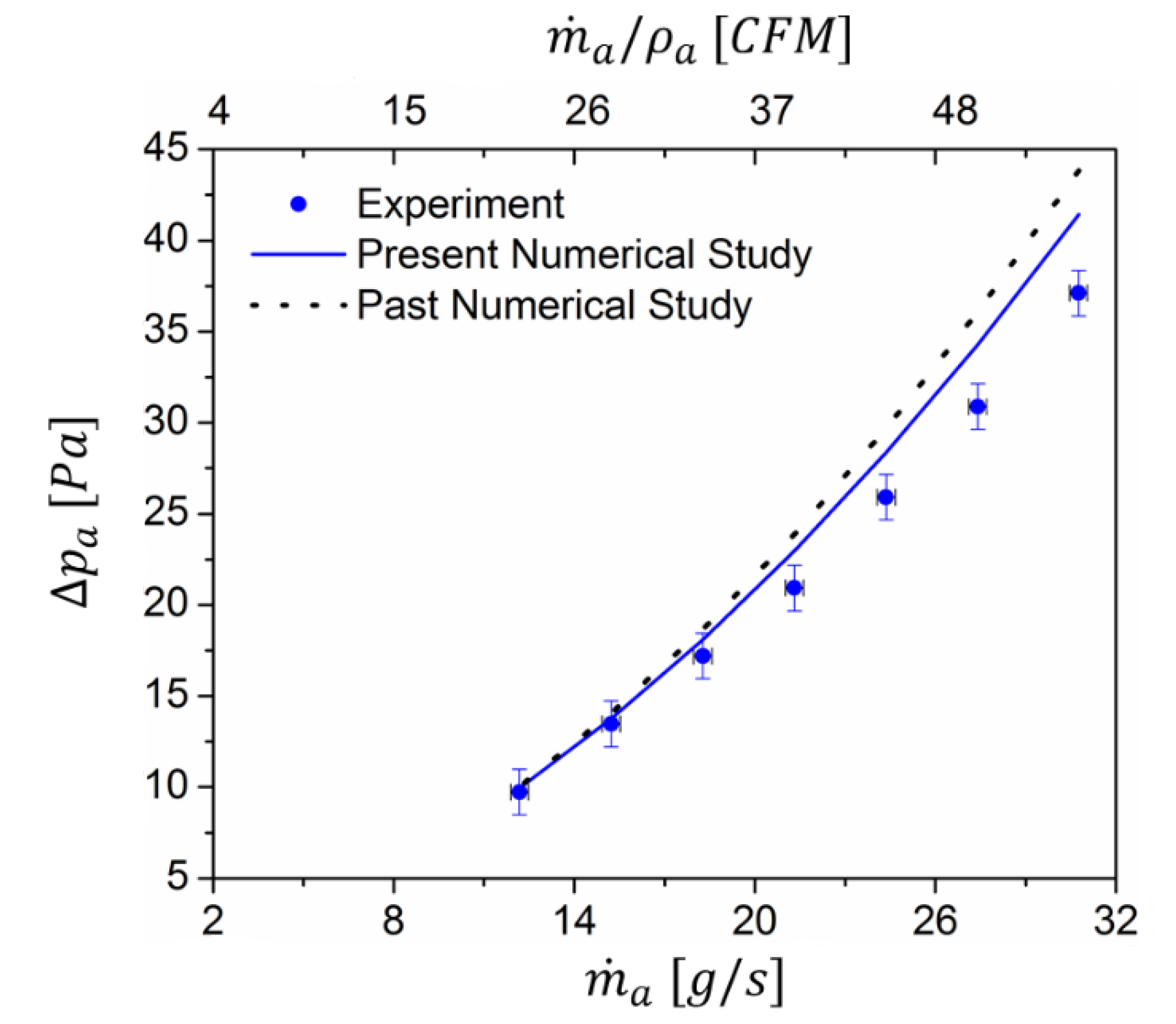
5.2. Validation of Numerical Results with Air-Side Testing Data
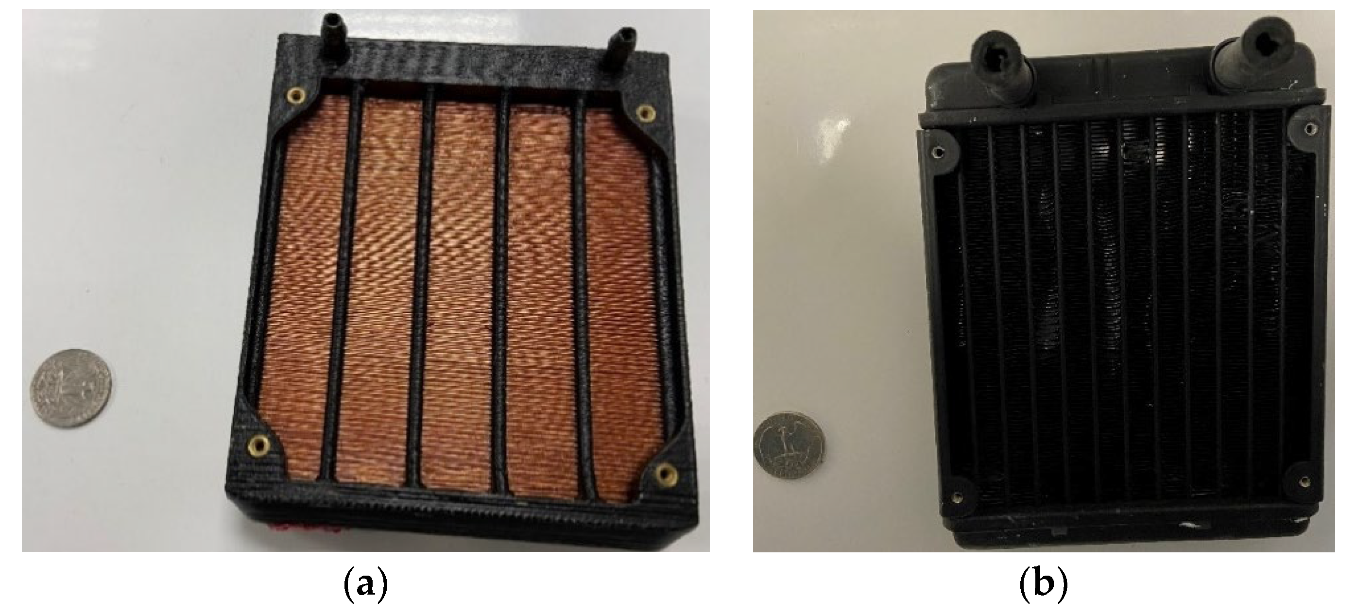
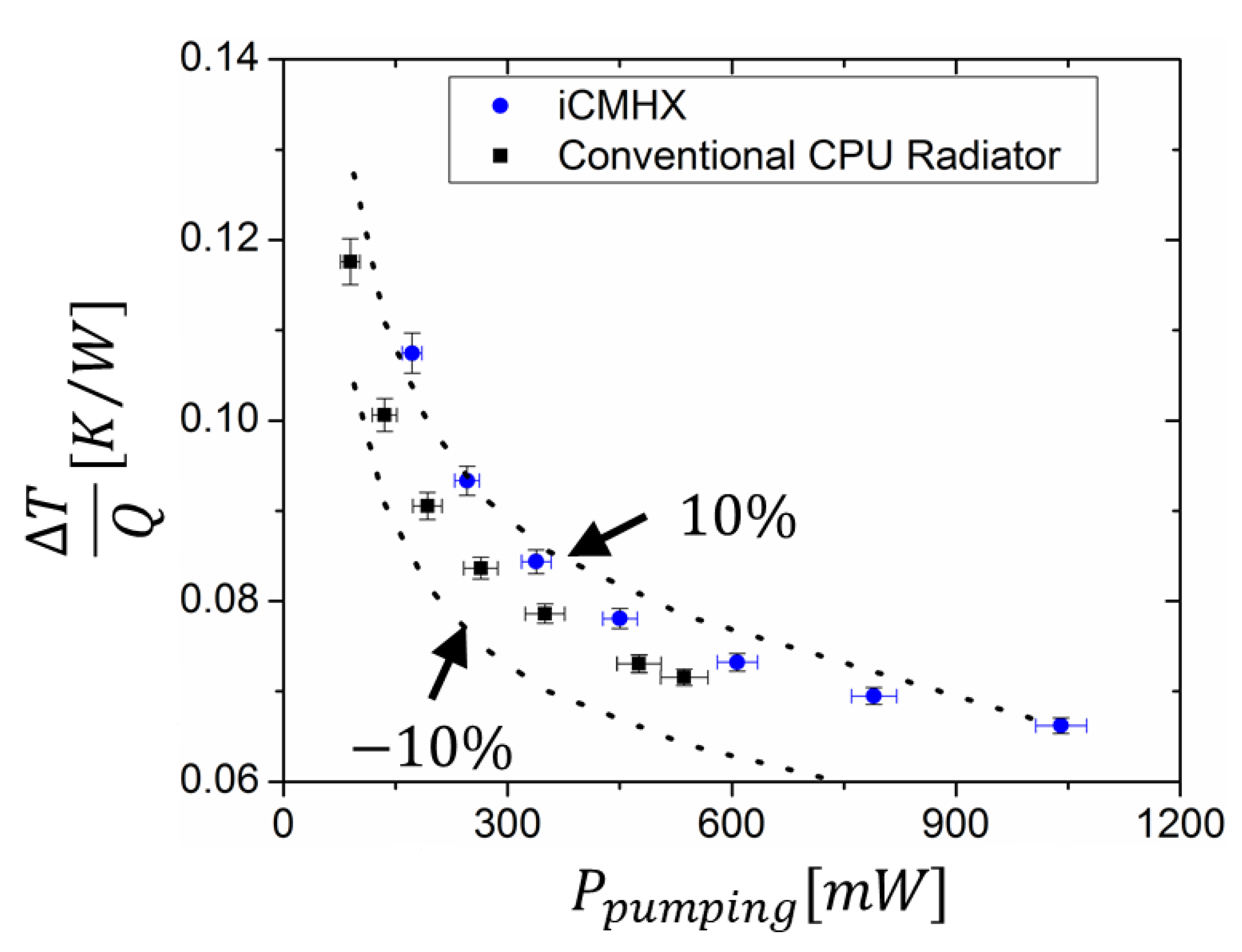
5.3. Comparison to a High-Performance, Commercially Available CPU Cooler Radiator
6. Conclusions
Author Contributions
Funding
Institutional Review Board Statement
Informed Consent Statement
Data Availability Statement
Acknowledgments
Conflicts of Interest
Nomenclature
| the ratio of maximum heat capacity to minimum heat capacity | |
| Euler number | |
| fin-parameter | |
| number of fins | |
| number of channels | |
| Nusselt number | |
| the direction along x axis | |
| axis | |
| axis | |
| Greek Symbols | |
| uncertainty | |
| fin effectiveness | |
| fin efficiency | |
| Subscripts | |
| air | |
| average | |
| conductive | |
| equivalent | |
| flow | |
| hydraulic | |
| longitudinal direction | |
| maximum | |
| minimum | |
| no flow | |
| overall | |
| ratio | |
| transverse direction | |
| thermal | |
| water | |
| Superscripts | |
| corrected | |
| cross-section | |
| inlet | |
| outlet | |
| surface | |
| Abbreviations | |
| acrylonitrile butadiene styrene | |
| coefficient of performance | |
| central processing unit | |
| data acquisition | |
| energy balance | |
| embedded fiber composite additive manufacturing | |
| fused deposition modeling | |
| heat exchanger | |
| integrated cross-media heat exchanger | |
| not applicable | |
| number of transfer units | |
| Scanning Electron Microscope | |
| Volume | |
References
- Qasem, N.; Zubair, S.M. Compact and microchannel heat exchangers: A comprehensive review of air-side friction factor and heat transfer correlations. Energy Convers. Manag. 2018, 173, 555–601. [Google Scholar] [CrossRef]
- Lyu, S.; Wang, C.; Zhang, C.; Royon, L.; Guo, X. Experimental characterization of a novel soft polymer heat exchanger for wastewater heat recovery. Int. J. Heat Mass Transf. 2020, 161, 120256. [Google Scholar] [CrossRef]
- Didmanidze, O.N.; Khakimov, R.T.; Parlyuk, E.P.; Bol’Shakov, N.A. Test Results of a Polymer Radiator of MTZ-80 Tractor Cooling System. Agric. Mach. Technol. 2020, 14, 55–60. [Google Scholar] [CrossRef]
- Chen, X.; Su, Y.; Reay, D.; Riffat, S. Recent research developments in polymer heat exchangers–A. review. Renew. Sustain. Energy Rev. 2016, 60, 1367–1386. [Google Scholar] [CrossRef]
- Githens, R.E. Flexible-tube heat exchangers. Chem. Eng. Prog 1965, 61, 55–62. [Google Scholar]
- Deisenroth, D.C.; Moradi, R.; Shooshtari, A.H.; Singer, F.; Bar-Cohen, A.; Ohadi, M. Review of Heat Exchangers Enabled by Polymer and Polymer Composite Additive Manufacturing. Heat Transf. Eng. 2017, 39, 1648–1664. [Google Scholar] [CrossRef]
- Mark, J. Physical Properties of Polymers Handbook; Springer: New York, NY, USA, 2007. [Google Scholar]
- Glouannec, P.; Chauvelon, P.; Feller, J.; Noël, H.; Ploteau, J.-P. Current passage tubes in conductive polymer composite for fluid heating. Energy Convers. Manag. 2008, 49, 493–505. [Google Scholar] [CrossRef]
- Xu, Y.; Ray, G.; Abdel-Magid, B. Thermal behavior of single-walled carbon nanotube polymer–matrix composites. Compos. Part A Appl. Sci. Manuf. 2006, 37, 114–121. [Google Scholar] [CrossRef]
- Hussain, A.R.J.; Alahyari, A.A.; Eastman, S.A.; Thibaud-Erkey, C.; Johnston, S.; Sobkowicz, M. Review of polymers for heat exchanger applications: Factors concerning thermal conductivity. Appl. Therm. Eng. 2017, 113, 1118–1127. [Google Scholar] [CrossRef] [Green Version]
- Zaheed, L.; Jachuck, R. Review of polymer compact heat exchangers, with special emphasis on a polymer film unit. Appl. Therm. Eng. 2004, 24, 2323–2358. [Google Scholar] [CrossRef]
- Smith, W.F. Solar Energy Absorber. U.S. Patent 4763641, 6 November 1987. [Google Scholar]
- Shuster, J.P.; Cesaroni, A.J. Heat Exchanger Fabricated from Polymer Compositions. U.S. Patent 4955435, 11 September 1990. [Google Scholar]
- Rasouli, E.; Strong, A.; Narayanan, V. High efficiency microchannel polymer heat exchangers for heating and cooling applications. ASHRAE Trans. 2020, 126, 341–348. [Google Scholar]
- Harris, C.; Despa, M.; Kelly, K. Design and fabrication of a cross flow micro heat exchanger. J. Microelectromechanical Syst. 2000, 9, 502–508. [Google Scholar] [CrossRef]
- Rajagopal, M.C.; Chang, H.C.; Man, T.; Kuntumalla, G.; Meng, Y.; Sundar, S.; Zhao, H.; Salapaka, S.; Shao, C.; Ferreira, P.; et al. Materials-to-device design of hybrid metal-polymer heat exchanger tubes for low temperature waste heat recovery. Int. J. Heat Mass Transf. 2019, 143, 118497. [Google Scholar] [CrossRef]
- Fugmann, H.; Schnabel, L.; Frohnapfel, B. Heat transfer and pressure drop correlations for laminar flow in an in-line and staggered array of circular cylinders. Numer. Heat Transfer Part A Appl. 2019, 75, 1–20. [Google Scholar] [CrossRef]
- Azzouz, K.; Boisselle, P.; De Vaulx, C. Heat Exchanger and Method for Manufacturing Same. International Patent WO2017162966A1, August 1994. [Google Scholar]
- Sahiti, N. Thermal and fluid dynamic performance of pin fin heat transfer surfaces. Ph.D. Thesis, Friedrich-Alexander Universitat, Erlangen-Nurnberg, Germany, 27 January 2006. [Google Scholar]
- Arie, M.; Hymas, D.; Singer, F.; Shooshtari, A.; Ohadi, M. Performance Characterization of a Novel Cross-Media Composite Heat Exchanger for Air-to-Liquid Applications. In Proceedings of the InterSociety Conference on Thermal and Thermomechanical Phenomena in Electronic Systems, ITherm, Las Vegas, NV, USA, 28–31 May 2019; pp. 933–940. [Google Scholar]
- Arie, M.; Hymas, D.; Singer, F.; Shooshtari, A.; Ohadi, M. An additively manufactured novel polymer composite heat exchanger for dry cooling applications. Int. J. Heat Mass Transf. 2019, 147, 118889. [Google Scholar] [CrossRef]
- Hymas, M.; Arle, M.A.; Singer, F.; Shooshtari, A.H.; Ohadi, M.M. Enhanced Air-Side Heat Transfer in an Additively Manufactured Polymer Composite Heat Exchanger. In Proceedings of the 16th IEEE InterSociety Conference on Thermal and Thermomechanical Phenomena in Electronic Systems, ITherm, Orlando, FL, USA, 30 May–2 June 2017; pp. 634–638. [Google Scholar] [CrossRef]
- Kailkhura, G.; Mandel, R.K.; Shooshtari, A.H.; Ohadi, M.M. Numerical Investigation of an Integrated Cross-Media Heat Exchanger (iCMHX) for Gas-to-Liquid Cooling Applications. In Proceedings of the 19th IEEE InterSociety Conference on Thermal and Thermomechanical Phenomena in Electronic Systems, ITherm, Orlando, FL, USA, 26–29 May 2020; pp. 501–509. [Google Scholar] [CrossRef]
- Kailkhura, G.; Mandel, R.K.; Shooshtari, A.H.; Ohadi, M.M. Experimental Study of a Set of Integrated Cross-Media Heat Exchangers (iCMHXs) for Liquid Cooling Applications in Desktop Computers. InterPACK 2020, 91, 1–58. [Google Scholar]
- Singer, F.; Deisenroth, D.C.; Hymas, D.M.; Ohadi, M.M. Additively manufactured copper components and composite structures for thermal management applications. In Proceedings of the 16th IEEE Intersociety Conference on Thermal and Thermomechanical Phenomena in Electronic Systems (ITherm), Orlando, FL, USA, 30 May–2 June 2017; pp. 174–183. [Google Scholar] [CrossRef]
- Hymas, S.; Dessiatoun, S.V.; Ohadi, M.M. Metal/Polymer Composite Additive Manufacturing (mfc-am) and Composite Structures Formed by mfc-am. U.S. Patent US20200016823, 16 January 2020. [Google Scholar]
- Nazari, M.; Karami, M.; Ashouri, M. Comparing the thermal performance of water, Ethylene Glycol, Alumina and CNT nanofluids in CPU cooling: Experimental study. Exp. Therm. Fluid Sci. 2014, 57, 371–377. [Google Scholar] [CrossRef]
- Pastukhov, V.; Maidanik, Y.; Vershinin, C.; Korukov, M. Miniature loop heat pipes for electronics cooling. Appl. Therm. Eng. 2003, 23, 1125–1135. [Google Scholar] [CrossRef]
- Lang, T.A.; Secic, M. How to Report Statistics in Medicine: Annotated Guidelines for Authors, Editors, and Reviewers; American College of Physicians: Philadelphia, PA, USA, 1997. [Google Scholar]
- Taylor, B.N.; Kuyatt, C.E. Guidelines for evaluating and expressing the uncertainty of NIST measurement results. NIST Tech. Notes 1994, 1297, 20. [Google Scholar] [CrossRef]
- Berbish, N.S. Heat transfer and flow behavior around four staggered elliptic cylinders in cross flow. Heat Mass Transf. 2010, 47, 287–300. [Google Scholar] [CrossRef]
- Tala, J.S.; Bougeard, D.; Russeil, S.; Harion, J.-L. Tube pattern effect on thermalhydraulic characteristics in a two-rows finned-tube heat exchanger. Int. J. Therm. Sci. 2012, 60, 225–235. [Google Scholar] [CrossRef]
- Hasan, A. Thermal-hydraulic performance of oval tubes in a cross-flow of air. Heat Mass Transf. 2005, 41, 724–733. [Google Scholar] [CrossRef]
- Ibrahim, T.A.; Gomaa, A. Thermal performance criteria of elliptic tube bundle in crossflow. Int. J. Therm. Sci. 2009, 48, 2148–2158. [Google Scholar] [CrossRef]
- Jang, J.-Y.; Yang, J.-Y. Experimental and 3-D Numerical Analysis of the Thermal-Hydraulic Characteristics of Elliptic Finned-Tube Heat Exchangers. Heat Transf. Eng. 1998, 19, 55–67. [Google Scholar] [CrossRef]
- Chen, Y.; Fiebig, M.; Mitra, N.K. Conjugate Heat Transfer of a Finned Oval Tube Part A: Flow Patterns. Numer. Heat Transfer Part A Appl. 1998, 33, 371–385. [Google Scholar] [CrossRef]
- Bergman, T.L.; Lavine, A.S.; Incropera, F.P.; DeWitt, D.P. Fundamentals of Heat and Mass Transfer; John Wiley & Sons: Hoboken, NJ, USA, 2011. [Google Scholar]
- Rodgers, P.; Goharzadeh, A.; Ali, O.A.E.; Eveloy, V. An experimental and numerical investigation of tube bank heat exchanger thermofluids. In Proceedings of the EuroSimE 2008–International Conference on Thermal, Mechanical and Multi-Physics Simulation and Experiments in Microelectronics and Microsystems, Freiburg im Breisgau, Germany, 20–23 April 2008; pp. 1–10. [Google Scholar] [CrossRef]
- Khan, W.A.; Culham, J.R.; Yovanovich, M.M. Convection heat transfer from tube banks in crossflow: Analytical approach. Int. J. Heat Mass Transf. 2006, 49, 4831–4838. [Google Scholar] [CrossRef]
- Tahseen, T.A.; Ishak, M.; Rahman, M. An overview on thermal and fluid flow characteristics in a plain plate finned and un-finned tube banks heat exchanger. Renew. Sustain. Energy Rev. 2015, 43, 363–380. [Google Scholar] [CrossRef] [Green Version]
- Gaddis, E.S.; Gnielinski, V. Pressure drop in cross flow across tube bundles. Int. Chem. Eng. 1985, 25, 1–15. Available online: https://www.osti.gov/biblio/6503251-pressure-drop-cross-flow-across-tube-bundles (accessed on 14 January 2020).
- El Gharbi, N.; Kheiri, A.; El Ganaoui, M.; Blanchard, R. Numerical optimization of heat exchangers with circular and non-circular shapes. Case Stud. Therm. Eng. 2015, 6, 194–203. [Google Scholar] [CrossRef]


| Fluid | Equipment | Specifications | |
|---|---|---|---|
| Water side | Chiller | ThermoNESLAB RTE 7 (R134A) 800 W heater | NA |
| Pump | Micropump I-Drive (Type 76,003) 0 to 12.33 g/s | NA | |
| Coriolis Flowmeter | Endress+Hauser Promass 83 A Nominal Diameter: 1/12” 0 to 27.7 g/s | 0.1% of measured value | |
| Manometer | 0 to 17.85 kPa | 50 Pa | |
| Parallel Thermopile | Omega T-type thermocouples | ||
| Air side | Blower | Baldor Industrial Motor—3Phase (F198 series) 0 to 89 g/s | NA |
| Pre-Chiller | Forma Scientific Model 2067 650 W heater | ||
| Rotameter | Fischer & Porter (Model No. 10A4557S) 0 to 32 g/s | ||
| Analogue Pressure Gauge | Magnehelic Dyer Instruments 0 to 64 Pa | ||
| Thermopile Parallel | Omega T-type thermocouples |
| iCMHX | Conventional Unit | |||
| Temperature Conditions | ||||
| 12.8–16.6 | 12.5–15.4 | |||
| 42.4–45.5 | 44–48 | |||
| Flow Conditions | ||||
| Air-side Test | Water-side Test | Air-side Test | Water-side Test | |
| 10–30.8 | 21.9 | 12–29 | 29.2 | |
| 9.5 | 3.5–9.5 | 9.6 | 3.6–9.6 | |
| Derived Quantities | |
|---|---|
| 1.8–3% | |
| 1.7–2.6% | |
| 1.1–2.2% | |
| 3.3–12% |
| Nominal | Measured | ||||
|---|---|---|---|---|---|
| (mm) | Average (mm) | Standard Deviation (mm) | Range (mm) | Number of Measurement Points | |
| 0.44 | 0.48 | 0.042 | 0.343–0.686 | 982 | |
| 0.44 | 0.42 | 0.045 | 0.275–0.566 | 1025 | |
| 1.4 | 1.4 | 0.15 | 0.472–2.78 | 941 | |
| 1 | 0.94 | 0.253 | 0.224–1.74 | 850 | |
| 2 | 1.79 | 0.18 | 1.23–2.13 | 106 | |
| 1 | 1.08 | 0.127 | 0.85–1.48 | 49 | |
| iCMHX | Conventional CPU Radiator | |
|---|---|---|
| Overall design | ||
| 16 | 15 | |
| 119.6 | 118 | |
| 119 | 109.75 | |
| 253.2 | ||
| 2.27 × 10⁵ | ||
| Polymer geometrical parameters | ||
| 19 | 7.23 | |
| 1.79 | 1.9 | |
| 1.08 | 0.13 | |
| 5 | 12 | |
| 6 | 13 | |
| Fin geometrical parameters | ||
| 1.4 | 1.241 | |
| - | 0.2 | |
| 0.9 | - | |
| 0.48 | - | |
| 0.42 | - | |
| 14 | - | |
| 84 | 94 | |
| Assumptions |
| Laminar flow, steady-state, incompressible flow |
| Constant fluid and material properties |
| Uniform fluid flow and temperature profiles at the inlets |
| Solver Details and Methods |
| PRESTO for pressure 1st order upwind for momentum and energy Coupled scheme for pressure and velocity |
| for energy |
Publisher’s Note: MDPI stays neutral with regard to jurisdictional claims in published maps and institutional affiliations. |
© 2022 by the authors. Licensee MDPI, Basel, Switzerland. This article is an open access article distributed under the terms and conditions of the Creative Commons Attribution (CC BY) license (https://creativecommons.org/licenses/by/4.0/).
Share and Cite
Kailkhura, G.; Mandel, R.K.; Shooshtari, A.; Ohadi, M. Numerical and Experimental Study of a Novel Additively Manufactured Metal-Polymer Composite Heat-Exchanger for Liquid Cooling Electronics. Energies 2022, 15, 598. https://doi.org/10.3390/en15020598
Kailkhura G, Mandel RK, Shooshtari A, Ohadi M. Numerical and Experimental Study of a Novel Additively Manufactured Metal-Polymer Composite Heat-Exchanger for Liquid Cooling Electronics. Energies. 2022; 15(2):598. https://doi.org/10.3390/en15020598
Chicago/Turabian StyleKailkhura, Gargi, Raphael Kahat Mandel, Amir Shooshtari, and Michael Ohadi. 2022. "Numerical and Experimental Study of a Novel Additively Manufactured Metal-Polymer Composite Heat-Exchanger for Liquid Cooling Electronics" Energies 15, no. 2: 598. https://doi.org/10.3390/en15020598
APA StyleKailkhura, G., Mandel, R. K., Shooshtari, A., & Ohadi, M. (2022). Numerical and Experimental Study of a Novel Additively Manufactured Metal-Polymer Composite Heat-Exchanger for Liquid Cooling Electronics. Energies, 15(2), 598. https://doi.org/10.3390/en15020598