1. Introduction
Contemporary technological advances seek the efficient exploitation of the vast wave energy toward the transition of the European countries to a carbon-neutral energy future. Accordingly, the technology of wave energy converters (WECs) has been rapidly evolving during the last few years, with the aim of delivering commercially competitive solutions characterized by energy effectiveness, adequate structural integrity, and cost efficiency. Among the various types of WECs proposed or developed so far [
1], heaving devices are considered nowadays one of the most advanced WEC technology [
2].
The design of heaving WECs relies heavily on the utilization of conventional, computationally efficient, linear numerical models for assessing the hydrodynamic behavior and, thus, the power absorption ability of the device under the wave action in frequency or time domain. However, nonlinear effects existing in the real physical problem may become important (e.g., at nearshore locations or at resonance conditions), and therefore, the deployment of nonlinear numerical models for simulating the interaction of the heaving device with the waves is required. Along these lines, Boussinesq-type numerical models accurately predicting nonlinear nearshore hydrodynamics could be utilized.
In previous works, Boussinesq-type numerical models were employed to simulate the generation and propagation of ship-borne waves (e.g., [
3,
4,
5,
6,
7,
8,
9,
10]). The ship was represented as a moving pressure disturbance by incorporating a pressure term in the momentum equation. In a similar way, Bingham [
11], Koutandos et al. [
12], and Eskilsson et al. [
13] used 1DH Boussinesq-type modeling equations to predict the wave-induced motion of a floating structure. In the above works, the pressure term was calculated in a simple way by considering a single static surface depression [
5,
7,
8,
9] or in a more complicated way by solving simultaneously an additional equation (the Laplace equation, as in [
12], or a depth-integrated momentum equation, as in [
13]). Lannes [
14] proposed together with the Boussinesq equations the simultaneous solution of an elliptic equation to determine the pressure exerted by the fluid on the floating body (see also [
15]). Quite recently, a Boussinesq-type model has been developed in [
16] for solving the problem of only the wave diffraction induced by a fixed truncated vertical cylinder.
With the aim of filling existing research gaps, the present paper highlights a 2DH Boussinesq-type numerical model with advanced features, developed for the simulation of nonlinear wave-heaving cylinder interaction. The model is based on the 2DH post-Boussinesq model of Karambas and Memos [
17], which is capable to describe the propagation of fully dispersive and weakly nonlinear waves over any finite water depth, and it has been applied in several research studies and engineering applications (indicative reference is made to [
18,
19]). The main advantage of the present nonlinear wave model is that it is a wavenumber-free model and, as far as the theoretical linear dispersion relation is concerned, the approach is exact. Thus, the model is able to describe the propagation of any nonlinear wave (or other sea surface disturbance) at any finite water depth. Following [
14], the wave-cylinder interaction is taken into account by solving simultaneously an elliptic equation that determines the fluid pressure applied on the floating body. Newton’s law is employed to form the body’s equation of motion in the vertical direction, and, thus, calculate the heave motion of the cylinder. The developed model is applied for the case of a fixed and a free-floating circular cylinder under the action of regular waves, as well as for a free-floating circular cylinder undergoing a forced motion in heave. Results are compared with those obtained using WAMIT©, which is based on the well-known boundary integral equation method (BIEM). It is worth noting that although the present approach is based on the post-Boussinesq model of [
17], it can be also deployed in any other Boussinesq-type model.
The remainder of the paper is organized as follows: In
Section 2, the 2DH post-Boussinesq model is presented, together with the elliptic equation that determines the pressure exerted by the fluid on the floating body. In this section, the numerical scheme and the equation of the partially immersed body’s heave motion under the action of waves are also described. In
Section 3, the results of the present investigation are presented and discussed in detail, while, finally, in
Section 4, the main conclusions of this study are cited along with suggestions for future investigation.
2. The 2DH Post-Boussinesq Model
2.1. Model Equations
The model’s momentum equations were extracted adopting a methodology based on the Fourier transform, leading to equations similar to the respective ones for long waves, incorporating a single additional frequency dispersion term. The latter is expressed through convolution integrals, which are estimated using appropriate impulse functions. Accordingly, the momentum equations are expressed as follows [
17]:
where
,
are, respectively, the depth-averaged velocity components along the
and
direction,
is the water density,
is the free surface elevation,
the gravitational acceleration,
is time, and
is the interior pressure exerted by the fluid on the bottom of the floating body. In Equations (1) and (2), the kernel
is given by [
17] as:
where
is the water depth and
.
Equations (1) and (2) together with the continuity equation
form the system of equations of the 2DH post-Boussinesq model.
The model is wavenumber free and, as far as the theoretical linear dispersion relation is concerned, the approach is exact (i.e., the model poses no restriction on the water depth). It also includes only a single frequency dispersion term to obtain the theoretical dispersion relation, while other Boussinesq-type models consider a significant number of terms with high order derivatives.
2.2. The Pressure in the Interior Domain
Due to the presence of the floating body, the horizontal plane is divided into two regions—the interior domain, defined as the projection of the wetted surface on the body, and the exterior domain. The interior pressure
of the last terms of the right-hand side of Equations (1) and (2) is calculated by numerically solving the following elliptic equation according to [
14]:
where
is the local instantaneous draught of the floating body (i.e., the instantaneous hull’s wetted surface and, consequently, the shape of a pressure disturbance),
is the total water depth—namely,
,
, and
are the nonlinear terms of the momentum equations (Equations (1) and (2)), whereas
and
are the dispersion terms (i.e., the integral terms) of Equations (1) and (2).
At the bottom boundary of the floating body, the following condition is applied:
where
is the pressure on the body bottom, which is calculated by adopting the pressure distribution of the Boussinesq equations [
12].
The terms
,
,
and
of Equation (5) are defined as follows:
In the case of other types of classical Boussinesq equations, the dispersive terms
and
can be written as (assuming constant depth)
Equation (5), as well as the pressure terms , of Equations (1) and (2), respectively, were applied only in the interior computational domain, while in the exterior domain, zero surface (atmospheric) pressure was considered, i.e., .
2.3. Numerical Scheme
The numerical solution was accomplished by a widely used simple and well-documented explicit second-order finite difference scheme, centered in space and forward in time on a staggered grid [
17]. The scheme conserves mass and energy for nonbreaking waves in a satisfactory manner. The discrete continuity equation is centered in the level points and the momentum equations in the flux points.
The continuity and the momentum equations are approximated by finite difference equations according to the selected explicit scheme. The convolution integrals of Equations (1) and (2) are calculated numerically using higher-order methods [
17].
The deployed finite differences scheme explicitly avoids the solution of a large system of algebraic equations, as in other Boussinesq formulations, which include a large number of terms.
The waves are generated inside the computational domain by simply adding a line source (a point source in the one-dimensional case) in the continuity equation [
20]. Wave absorption at the open boundaries of the computational domain is achieved using the sponge layer technique according to [
21].
2.4. Floating Body Dynamics
The equation of the heave motion for the partially immersed body’s dynamics under the action of regular waves is described by Newton’s law in the
direction as follows:
In Equation (13),
is the vertical displacement of the floating body,
is the submerged mass of the body,
is the heave added mass (hydrodynamic mass coefficient),
is a heave damping coefficient resulting from various sources (e.g., viscous damping),
is the heave hydrostatic restoring force coefficient, and
is the vertical exciting force. The latter quantity is obtained by integrating the interior pressure
derived from the numerical solution of the elliptic equation (Equation (5)) over the wetted surface of the body
as follows:
where
is the normal unit vector along
direction.
In addition to the above, the horizontal (along
) exciting force,
, can be calculated as follows:
where
is the pressure on the body sides, calculated by adopting the pressure distribution of the Boussinesq equations [
12], and
is the normal unit vector along the
direction.
In the case of a heaving circular cylinder with radius
and draft (at rest)
, as examined in this investigation, the submerged mass
is equal to
and its heave hydrostatic restoring force coefficient
is equal to
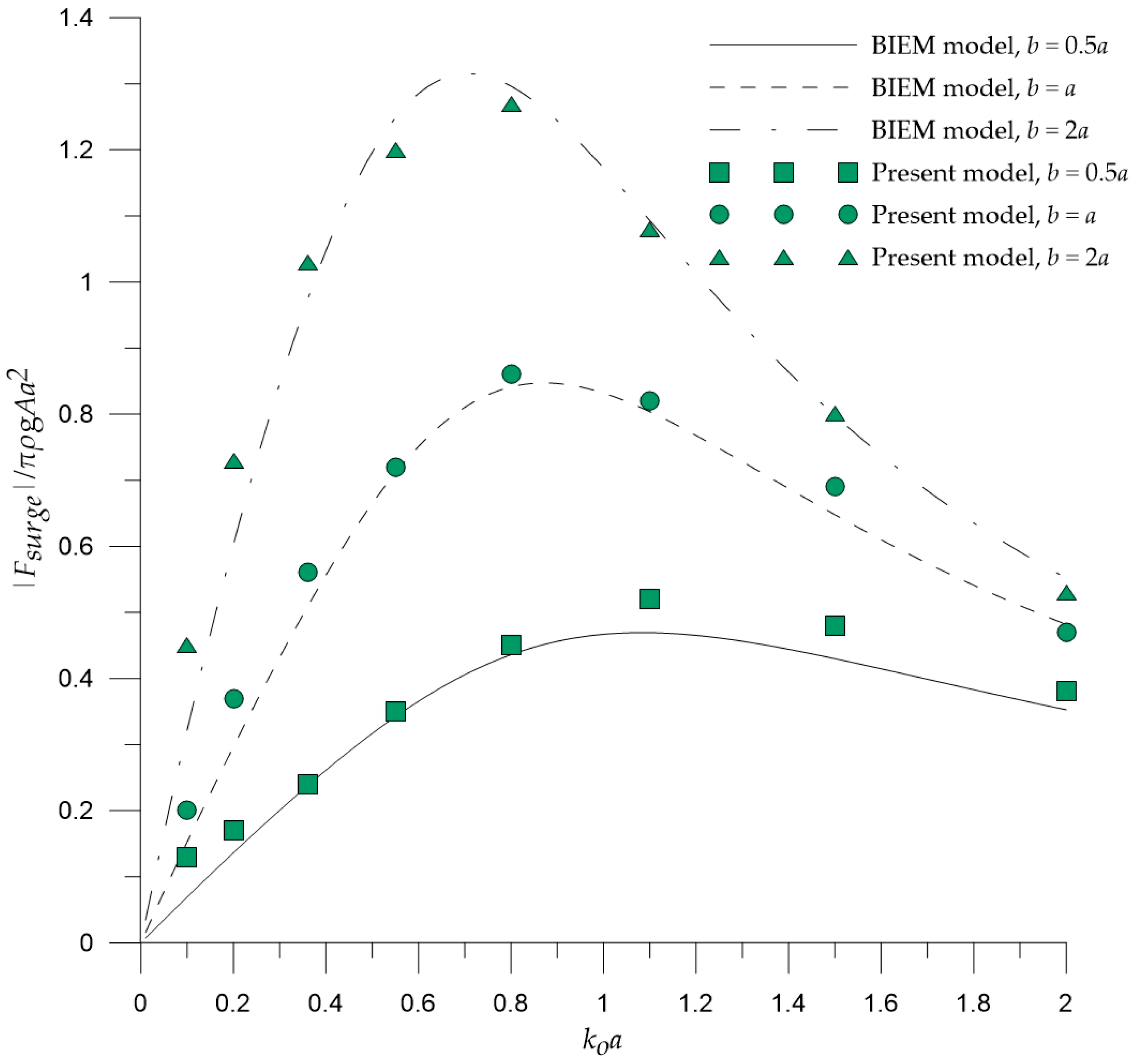
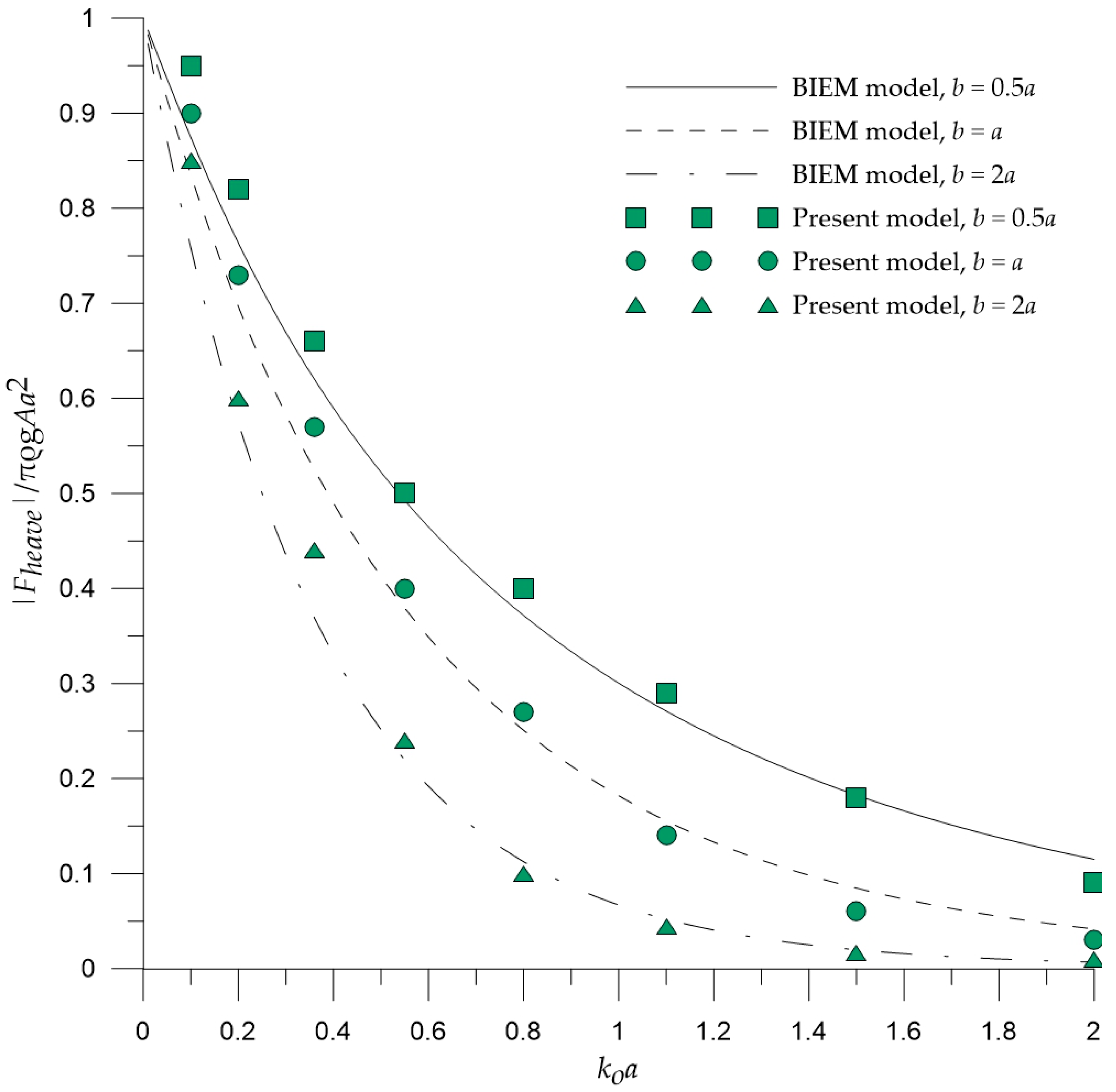
[
22]. As for
(Equation (13)), this frequency-depended coefficient was obtained in the present paper using WAMIT© (2006) code [
23], which is based on the well-known BIEM. The relevant frequency domain linear hydrodynamic analysis under unit-amplitude regular waves assumes incompressible and inviscid fluid, as well as irrotational flow. Thus, the fluid motion is described by introducing the velocity potential, which satisfies the Laplace equation everywhere in the fluid domain. The corresponding boundary value problem is formed by imposing the well-known linearized boundary conditions on the free surface, on the sea bottom, and on the floating body [
23,
24]. The boundary integral equations for the unknown velocity potentials on the boundary of the body are formed utilizing Green’s theorem, and the boundary value problem is solved by deploying a three-dimensional high-order panel method [
23,
24]. Subsequently, all physical quantities describing the hydrodynamic behavior of the floating body (e.g., heave exciting force and hydrodynamic coefficients, heave response, etc.) were calculated. It is worth noting that WAMIT© was also deployed in the present paper in order to compare its results with those obtained from the 2DH post-Boussinesq model.
4. Conclusions
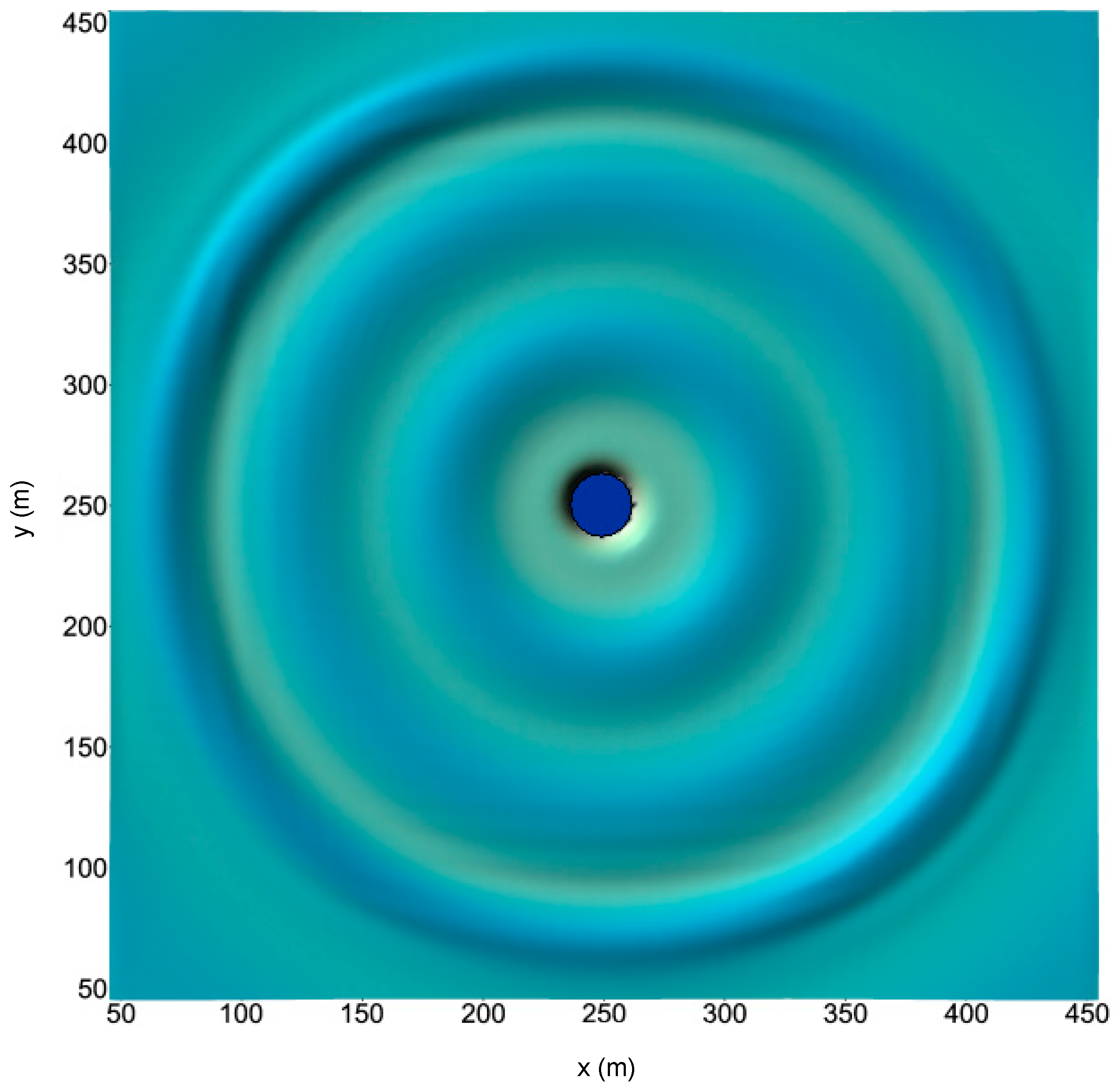
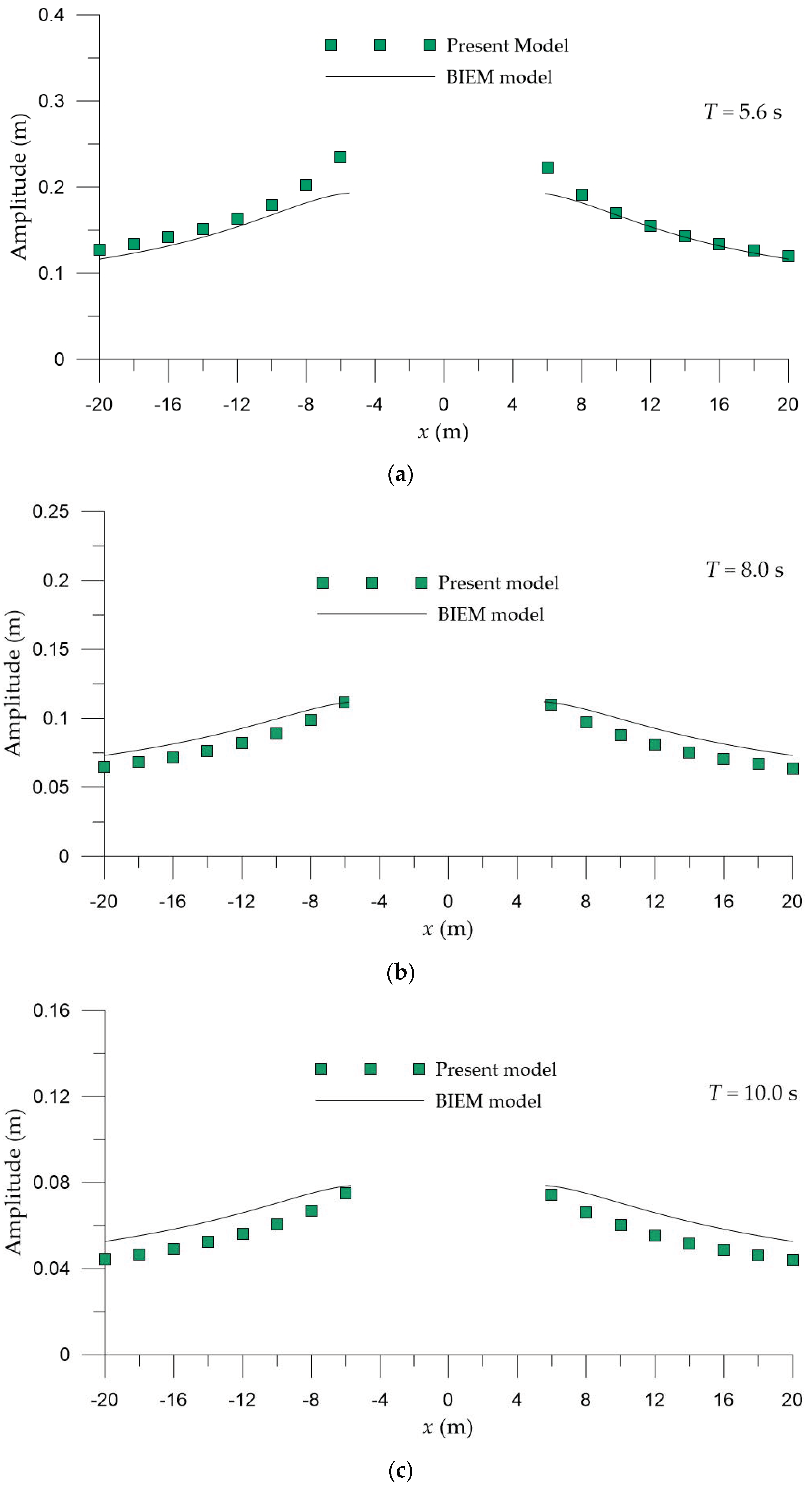
In the present work, a 2DH post-Boussinesq numerical model for the simulation of nonlinear wave-heaving cylindrical interaction was developed and presented. The model is able to describe the propagation of any nonlinear wave or other sea surface disturbance at any finite water depth, while the wave-cylinder interaction was taken into account by solving simultaneously an elliptic equation that determines the fluid pressure applied on the floating body. The model was applied for three different cases of a circular cylinder (a fixed and a free-floating cylinder under the action of regular waves, and a free-floating cylinder undergoing a forced motion in heave) in order to (a) compare results with those obtained using a BIEM model and (b) demonstrate the ability of the model to capture effectively the main aspects of the examined physical problem.
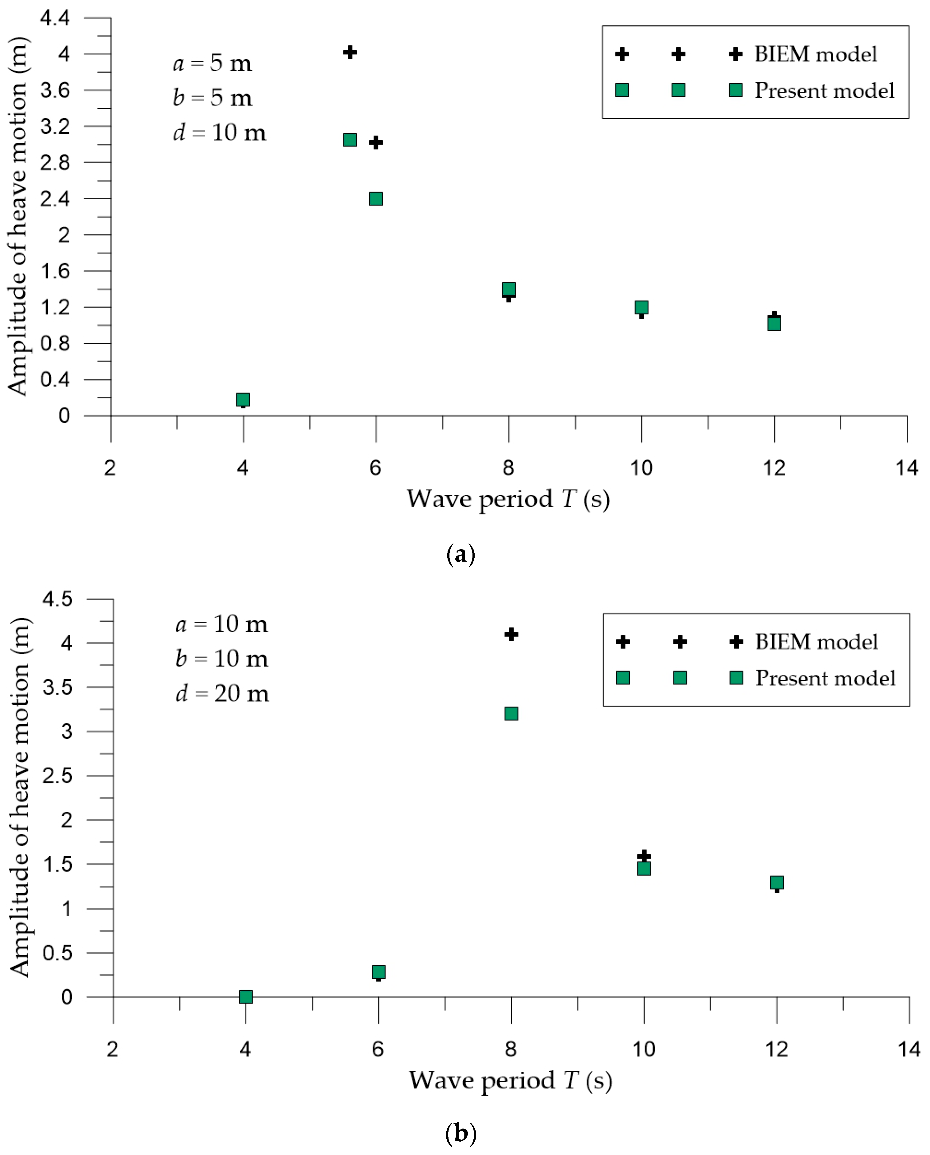
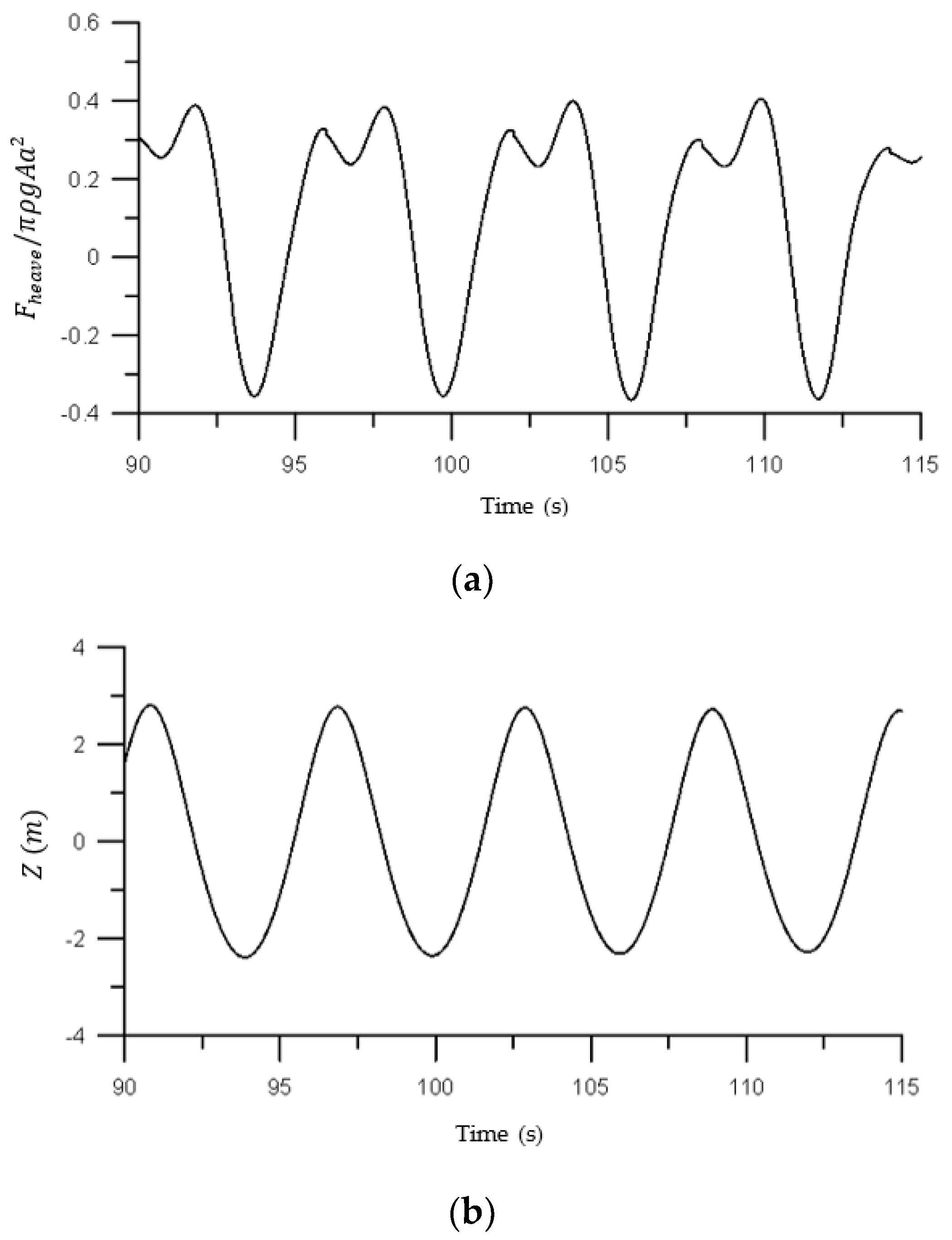
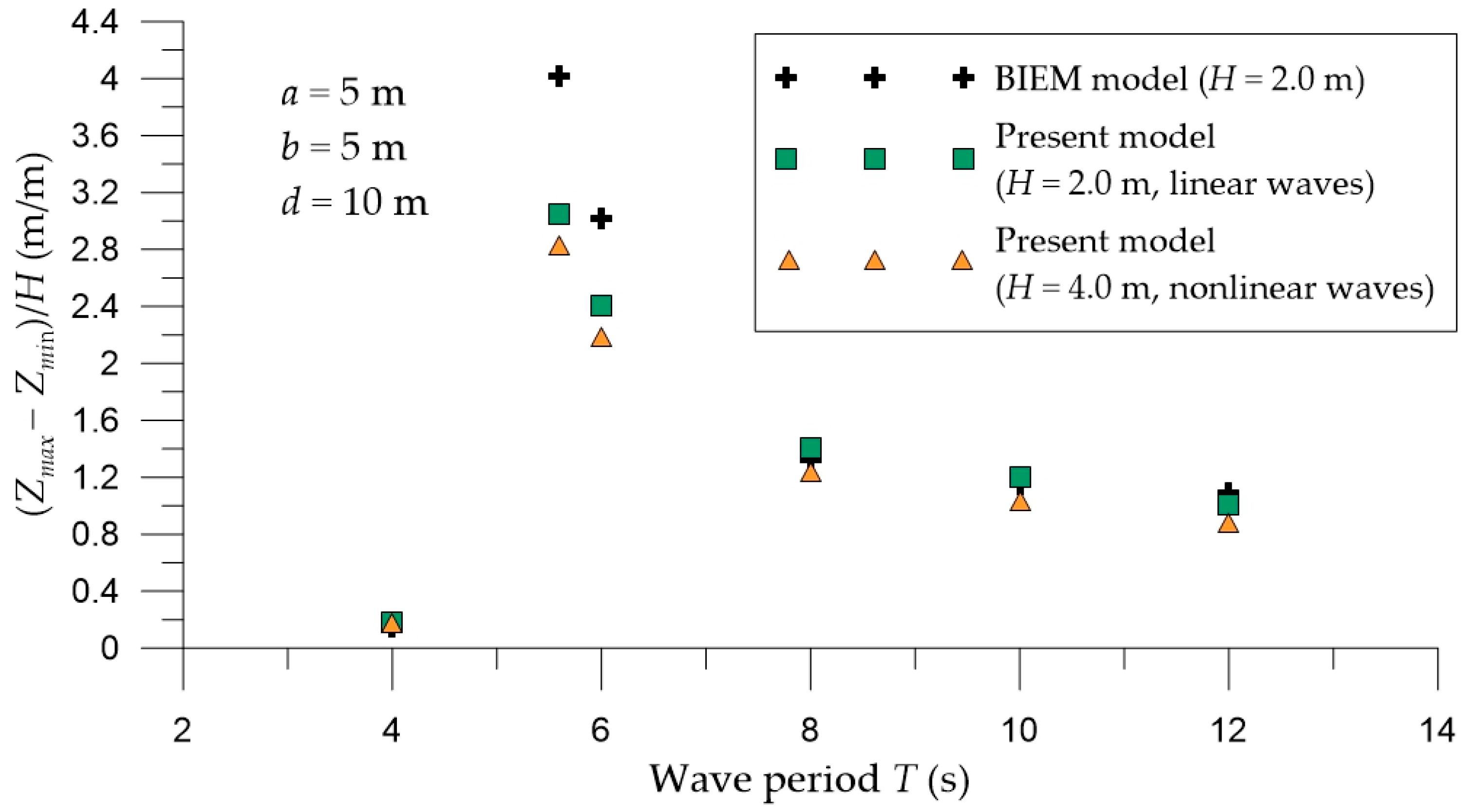
In the case of a fixed circular cylinder under the action of regular waves, the results of the 2DH post-Boussinesq model efficiently illustrated the foreseen effects of the nondimensional wavenumber and the nondimensional cylinder’s draft on the heave and surge exciting forces. Similarly, the developed numerical model effectively captured the anticipated features of the wave elevation and the heave response variation for a free-floating circular cylinder under a forced motion in heave and under the action of regular waves, respectively.
For all cases examined, the results of the 2DH post-Boussinesq model showed very good agreement with those obtained using the BIEM model. The most pronounced differences were observed in the case of the heave response of the free-floating circular cylinder under the wave action at the wave period range, where resonance phenomena occur. In this period range, numerical round-off and truncation errors introduced in the numerical schemes of the present model (in the solution of both the hydrodynamic and motion equations) led to smaller values of the heave motion, compared with those of the BIEM model.
The present model requires much more computational time, compared with the applied BIEM model. However, it has the advantage of simulating both near- and far-field (propagation) effects of heaving cylinders over a variable bathymetry, as well as the interaction of these structures with nonlinear irregular waves.
Along these lines, the present model could be deployed in order to assess the performance of a heaving WEC under the action of nonlinear regular and/or irregular waves, by introducing the power take-off system forces in the equation of motion. The model could be also further extended to deal with arrays of heaving cylinders or WECs, enabling the assessment of the impacts of these multi-body configurations on the surrounding wave field, especially, at nearshore locations.


