Article

Reframing the Selection of Hydraulic Turbines Integrating Analytical Hierarchy Process (AHP) and Fuzzy VIKOR Multi-Criteria Methods

by
Rudimar Caricimi
1,
Géremi Gilson Dranka
2,3,
Dalmarino Setti
1 and
Paula Ferreira
3,*
1
Industrial and Systems Engineering Graduate Program (PPGEPS), Federal University of Technology—Paraná (UTFPR), Pato Branco 85503-390, Brazil
2
Department of Electrical Engineering, Federal University of Technology—Paraná (UTFPR), Pato Branco 85503-390, Brazil
3
ALGORITMI Research Center/LASI, University of Minho, 4800-058 Guimarães, Portugal
*
Author to whom correspondence should be addressed.
Energies 2022, 15(19), 7383; https://doi.org/10.3390/en15197383
Submission received: 31 August 2022 / Revised: 19 September 2022 / Accepted: 22 September 2022 / Published: 8 October 2022

Abstract

:
Before selecting a proper hydraulic turbine for power generation, conflicting factors frequently emerge from the wide range of available technology alternatives. The preliminary selection of hydraulic turbines (PSHT) has been usually carried out by overlooking and/or overshadowing downstream and upstream processes. The development of a new conceptual framework that allows for including more parameters into the decision-making process at company levels is still required to avoid the danger of engaging in a one-dimensional approach, which would not only result in a reduced and simplistic vision of the choice but would also overlook the trade-offs between individual aspects and the possible unintended side-effects. This paper aims to provide empirical evidence for the PSHT by proposing a well-thought-out framework based on a mixed methodology approach (analytical hierarchy process (AHP) and fuzzy-VIKOR multi-criteria methods) and focused on small hydropower projects. A total of 16 criteria are proposed and divided into 4 main categories—(i) turbine performance, (ii) turbine and generator costs, (iii) other equipment costs, and (iv) civil costs. Findings reported here reveal a specific alignment between investors’ preferences and experts’ judgments with real market practices. The 16 proposed criteria can be further considered to support the decision-making process for PSHT in different head and flow conditions.

1. Introduction

In the new global economy, including sustainability aspects in decision-making has become a central issue for a cleaner and affordable energy transition. Different pathways to decarbonize energy-related activities have been proposed by the uptake of climate-friendly innovations and novel technologies (see [1,2], for example). At the same time, sustained growth in electricity generation from renewable energy sources (RES) has been seen worldwide [3]. The joint use of RES and energy efficiency measures (EEMs) [4,5] might have a significant effect on decreasing the level of greenhouse gas (GHG) emissions and, at the same time, supporting the achievement of the goals proposed in the Paris agreement to strengthen the world responsiveness to the threat of climate change [6].
Hydroelectricity is considered a proven technology and offers advantages over other power-producing facilities, including reduced GHG emissions, high efficiency, low operating and maintenance costs, and a high level of reliability [2,7,8]. The worldwide installed capacity from hydropower sources reached 1292 GW in 2018, representing 62% of the overall electricity production among RES (4200 TWh) [9]. The remaining global hydropower potential is still high (9.49 PWh), although only approximately 5.67 PWh is supposed to be exploited in an ecological scenario [10]. This high hydropower potential also suggests new project opportunities for the future, even considering the existence of trade-offs related to constructing new hydropower plants.
Small hydropower plants (SHP) have been considered “one of the most environmental friendly cost-effective energy technologies for generation of electrical power [11]”. Breeze [12] highlights that “high-head sites are often preferred because smaller turbines and smaller water flows can be used”. SHPs present a set of advantages compared to traditional power supply options, including their high reliability, high-efficiency levels, low maintenance costs, and storage capacity (depending on the construction scheme) [13,14]. Furthermore, small-scale hydropower systems usually have a shorter construction period, possible subsidies on capital costs, do not require large areas, present high-capacity factors and are considered a safer and waste-free technology [15]. SHPs also exhibit minor environmental impacts compared to traditional power sources acting as decentralized energy resources improving network stability and reducing transmission losses [16]. However, regardless of these advantages, the current worldwide installed capacity of SHPs represents only 4.5% among RES, and nearly 66% of the overall world’s hydropower potential remains untapped [17].
The technical aspects of using hydraulic turbines in hydropower plants have been widely discussed in the literature. Recent research developments in the field have been addressed by previous research, including, for example, the material selection for hydraulic turbines [18]. Based on operating data and expert elicitation, the ranking and prioritization of the risk factors responsible for hydraulic turbine equipment failures have been performed in [19]. An overview of the recent efforts to increase hydraulic turbines’ operational range to reach exceptional flexibility levels has been investigated in [20]. Ref. [21] proposed a method for sizing and siting SHP projects using geographic information systems (GIS) capabilities. In contrast, the selection of turbines for ultra-low-head (ULH) power plants by evaluating potential sites for these enterprises has been dealt with by Zhou and Deng [22]. An optimization model has been developed by Ibrahim et al. [23] for the preliminary design of run-of-river projects. Yildiz [24] proposed an evolutionary algorithm to optimize the design of run-of-river projects. The algorithm maximizes a set of parameters, including the type, number, discharge of turbines, and penstock diameter and length. An algorithm has been proposed by Nasir [25] to design micro-hydro power plants based mainly on the head and flow rate data. A review of micro-hydropower turbines for low-head applications is undertaken by Elbatran et al. [26], focusing on the different categories, performance, cost, and operation aspects.
Despite the fundamental role of SHPs worldwide, there has been little research on the methods for selecting the most suitable hydraulic turbine for a given hydropower project. The turbine selection process is considered “one of the most difficult decisions in the design of a hydropower plant [24]”. The decision-making process is complex and subjected to conflicting and interrelated technical, environmental, and economic criteria. Sangal et al. [27] reviewed the optimal selection of hydraulic turbines. The optimal choice of hydraulic turbines focused on SHPs has been discussed in [28] for a Nigeria case study. At the same time, there has also been disagreement on the criteria for selecting the most suitable hydraulic turbine, mainly for small-scale hydropower projects. Williams and Upadhyay [29] addressed the turbine selection process focused on SHP projects by considering the capital cost per kW output, ease of installation, average turbine lifetime, local manufacture and local repair/maintenance capability criteria. In a follow-up study [27], the need to address the efficiency, constructability, cost, maintenance, serviceability, portability, and scope of modularity criteria was reported. Williamson et al. [30] emphasized the importance of including the efficiency, power, civil structures, portability, modularity, and maintenance and serviceability criteria in the hydraulic turbine’s selection process.
The key stages related to the development of a hydropower project are illustrated in Figure 1 [31], which can be summarized as follows: The physical aspects of a SHP induces the types of turbines employed and the civil structures required for the deployment and, therefore, influence the cost and economic benefits generated by the project [8]. Stage 1 (Feasibility) can be split into (i) the opportunity identification, (ii) preliminary turbine selection, (iii) preliminary design, and (iv) pre-feasibility study, as illustrated in Figure 1. The planning phase (Stage 2—Planning) can be split into three key stages: schedule preparation, final feasibility study, and decision-making for execution [32]. The next stage (Stage 3—Construction) deals with the civil structures, i.e., related to the construction of the hydropower plant, including manufacturing, delivery, and equipment installation. The last stage (Stage 4—Start-up) is responsible for conducting a set of tests (e.g., load, vibrations, temperature, safety systems, protections, power test, load rejections, and index tests) until the full operation is achieved.
The preliminary study for selecting the most suitable hydraulic turbine for a hydropower project is complex. Understanding the complexity associated with the turbine selection phase is vitally crucial since inadequate selection may under or overestimate the real turbine needs for a given hydropower project. It might also deeply impact the capital, operational, and maintenance costs and, therefore, future project cash flows [33]. However, the preliminary selection of hydraulic turbines (PSHT) has been traditionally performed based on the previous knowledge background of industry experts by applying two approaches: (i) the rule of thumb (practical approach) (i.e., based on the available manufacturer’s information) and/or using (ii) the scientific approach (i.e., based on simplified calculation methods).
Although the current methods for the PSHT have proven useful, research has consistently shown that the preliminary selection has been made based on empirical evidence and can be adversely affected under certain conditions. Therefore, although there is no one-size-fits-all solution regarding the hydraulic turbine selection process, this problem is yet to be explored and calls for an innovative framework approach. The development of a new methodology that allows to include more parameters into the decision-making process at company levels is still required to avoid the danger of engaging in a one-dimensional approach, which would not only result in a reduced and simplistic vision of the choice but would also overlook the trade-offs between individual aspects and the possible unintended side-effects.
On the other hand, the proper selection of a hydraulic turbine can also be performed using multi-criteria decision making (MCDM) methods. MCDM deals with decisions involving the choice of the best alternative among a set of options. It has been widely applied in different fields, including designing or managing production systems and logistics and applications in the renewable energy sector (e.g., [34,35,36,37,38]). MCDM is also considered a suitable tool in the PSHT since qualitative and quantitative criteria can be considered for decision-making. However, previous research that attempted to employ such MCDM practices is scarce. Therefore, this paper proposes a more efficient methodology based on a multi-criteria approach for the PSHT. The proposed framework considers the interdependencies between the cost and technical constraints surrounding the hydraulic turbine selection process. The methodology has been designed and is best suited for selecting hydraulic turbines for SHPs and expects to fill this field gap and facilitate the knowledge exchange between the academy and industry. The proposed methodology extends beyond the cases addressed as it may provide valuable lessons for other decision-making processes related to the most suitable turbine choice for a given SHP project. Still, it can also be extended to evaluating different turbine ranges, such as hydraulic turbines for larger hydropower projects.
This paper is divided into five main sections. This first section provides background information on the subject. A theoretical background on the fundamentals of hydraulic turbines and multi-criteria approaches is then addressed in Section 2. The methodological approach is further described (Section 3), together with the presentation of the proposed framework. The paper proceeds by presenting the main research findings based on a real case-study application in Section 4. Finally, Section 5 draws together the key results of the research, including the implications for policymakers and possible avenues for further investigation.

2. Theoretical Background

This chapter highlights the key theoretical concepts associated with this research paper. The first section provides the fundamentals of hydraulic turbines, including the most common types and standard practices for the PSHT process. The second section attempts to overview multi-criteria decision making (MCDM) methods briefly.

2.1. Fundamentals of Hydraulic Turbines

Hydraulic turbines convert water pressure into mechanical shaft power, which drives electricity generators. The available output power (watts) is proportional to the product of the net head and flow rate, as illustrated in Equation (1) [39,40], where P is the mechanical power produced at the turbine shaft (watts), ρ is the density of water (kg/m3), g is the acceleration due to the gravity (m/s2), H N is the net head of water across the turbine (m), Q is the flow rate passing through the turbine (m3/s), and η is the hydraulic efficiency of the turbine.
P = ρ   ·   g   ·   H N   ·   Q   ·   η
Pelton, Francis, and Kaplan models are considered the most commonly employed turbines for hydroelectricity production and are distinguished mainly by their runner’s shape. Traditionally, Pelton turbines (PT), Francis turbines (FT), Kaplan turbines (KT) present different configurations based on the shaft or generator position. For PT, there are two primary configurations: horizontal (HP) (up to three jets) and vertical (VP) (from four to six jets). FT can be classified into vertical francis (VF), single horizontal francis (SHF), and double horizontal francis (DHF). The most traditional KT configurations are the Kaplan with the spiral casing and the one with a vertical shaft (VK). There are other tubular models including the upstream S-type (UST), downstream S-type (DST), both with the shaft in the horizontal position [41] and the Vertical S-type/Saxo (VST) [42], with the shaft in the vertical position. There are several other types of available hydraulic turbines usually well suited for micro and pico hydro applications, including the cross-flow/Banki, Turgo, propeller, Deriaz, Kinetic and Archimedes Screw. A full discussion of these types of hydraulic turbines lies beyond the scope of this study.
Several factors can affect the selection of a suitable turbine configuration, including the site location and the operating regimes [43]. The PSHT process can be iterative and usually starts by verifying the net head ( H N ) and estimated flow rate ( Q ) available on-site [27,44], which generally defines the size of the hydraulic turbine. There are two main approaches typically employed in the PSHT: (i) the rule of thumb (practical approach) and (ii) the scientific approach [45]. The rule of thumb approach (i) chooses the most suitable hydraulic turbine for a given hydropower project based on the net head and flow rate conditions of a river, which are compared to standard charts, as shown in Figure 2 (see the examples in [27,46]). Therefore, selecting the most appropriate turbine for this practice-based approach can be performed based on the information extracted from manufacturers (e.g., using available catalogs). Kaunda et al. [44] highlight that manufacturers recommend various turbine types based on the net head and flow rate information, which can guide the turbine’s choice.
The second-largest approach widely used in real applications for the PSHT is based on the scientific approach (ii). For this case, the turbine is selected based on its specific speed ( N s ) [27,45,47], as illustrated in Equation (2), where N is the nominal turbine speed (rpm), with P in kW and H N in meters. The specific turbine speed ( N s )   is defined as the speed—in revolutions per minute (rpm)—in which a turbine of homologous design would operate if the runner were scaled down to a size that developed one metric horse power under one meter for the net head. Table 1 presents the typical range for the specific speed considering the most typical hydraulic turbines [48,49].
N s = N P   ·   1.358 ) H 1.25
Analyzing Figure 2 and Table 1, an intersection region in the transition between the different types of turbines can be noted. Therefore, the decision-maker might have other options depending on the approach used. Based on this context, this paper proposes a framework for the PSHT, considering the most relevant criteria, which have been defined based on a systematic literature review. The proposed framework can be used jointly with the traditional approaches previously mentioned.

2.2. Multi-Criteria Decision Making (MCDM) in Renewable Applications

Multi-criteria decision making (MCDM) is usually employed for solving complex decision-making problems involving quantitative and qualitative factors [50]. The most traditional employed methods are the AHP (25.6%); TOPSIS (11.4%); ÉLECTRE (8.6%); PROMETHEE (6.6%); and VIKOR (3.6%) [50]. Recently, considerable literature has grown around the employment of MCDM approaches focused on renewable energy decisions. The most significant recent developments in this direction have been related to ranking power sources’ best choices.
A state-of-the-art review focused on decision support methods applied to renewable and sustainable energy was carried out by Strantzali and Aravossis [51]. Suganthi et al. [52] presented a systematic review of the most used MCDM methods for renewable energy systems. Siksnelyte et al. [53] reviewed research papers on both energy sustainability issues and MCDM techniques using the SWOT analysis and highlighted the usefulness and popularity of MCDM in dealing with energy sustainability problems. The common use of fuzzy-VIKOR and AHP techniques to define the best alternative for renewable energy in Istambul is investigated in [54]. A comparative analysis among VIKOR, TOPSIS, WSM (weighted sum method), and ÉLECTRE MCDM methods for ranking renewable energy sources in Taiwan was studied in [55], whereas a hybrid MCDM model based on benefits, opportunities, costs, and risks (BOCR) and analytic network process (ANP) techniques to prioritize energy sources in Turkey is addressed in [56]. Tasri and Susilawati [57] associated Fuzzy with AHP to select the best energy alternatives for Indonesia. In Pakistan, the assessment of sustainable energy planning strategies was addressed by Solangi et al. [58] through an integrated SWOT-AHP and Fuzzy-TOPSIS approach, whereas Wang et al. [59] focused on selecting renewable energy strategies using fuzzy-AHP and SWOT methods.
Multi-criteria decision methods have also emerged as a powerful tool focused on selecting the best places for hydropower projects. Supriyasilp et al. [60] employed a MCDM technique to select the best sites for hydropower projects in Thailand, taking stakeholder involvement, electricity generation, environment, socio-economics, engineering, and economics aspects into account. Economic, technical, environmental, and socio-political criteria have been considered by Rosso et al. [61], which adopted the AHP method to solve conflicts of interest among stakeholders for a SHP project placed on mountain areas. Kumar and Singal [62] employed a MCDM method to select the best operating site based on their current performance regarding the hydroelectric operational strategies. The combined use of the AHP and TOPSIS methods was employed by Özcan et al. [14] for maintenance strategy selection in hydropower projects. Fuzzy-AHP and TOPSIS have also been considered by Majumder et al. [63] to select indicators to analyze performance-related reliability in hydropower plants. A MCDM method has also been employed to choose material for the production of penstock [62], whereas Adhikary et al. [64] addressed the selection of suppliers/manufacturers of hydraulic turbines for SHPs in India. The use of MCDM with a particular focus on selecting hydraulic turbines for low head and very low power (less than 5kW) facilities is presented in [30].

3. Materials and Methods

This research paper focuses on the PSHT for SHP projects (Stage 1—Feasibility)—see Figure 1, which is also positioned in the first stage of the standard IEC 61116 [65]. The research follows a mixed (quantitative and qualitative) approach within the research design.
The innovative aspects of the present research come from the proposed framework, which combines the most relevant criteria defined in the literature review with the combined use of MCDM methods (AHP and fuzzy-VIKOR) for the PSHT. The AHP is used to determine the criteria weight, and fuzzy-VIKOR is considered to obtain a solution with feasible alternatives and not only considering the hierarchy of alternatives.
The detailed conceptual framework proposed in the present research for the PSHT is illustrated in Figure 3. The general methodological approach considers three major phases: 1. Literature Review and Criteria Definition; 2. Case Study; and 3. Application of MCDM.
Firstly, a literature review was conducted (Step 1.1—Phase 1) using Proknow-C [66] and snowballing [67] techniques to define the most relevant criteria for the PHST (Step 1.2—Phase 1). The selected criteria will be presented in the results section. Phase 2 is responsible for the project characterization (Step 2.1), which includes the characterization of the case study, data collection, and analysis, followed by the definition of the alternatives (Step 2.2). The definition of the first set of alternatives can be performed using the traditional approaches highlighted in the theoretical background section. The methodology proceeds to the MCDM application (Phase 3). The weights for each criterion are first defined (Step 3.1) based on the investor’s preferences using the AHP method. The alternatives’ performance can be verified (Step 3.2) by comparing the alternatives using fuzzy language. The fuzzy-VIKOR method is applied in Step 3.3 to solve the subjective preferences, and the decision-making process can finally be conducted to choose the hydraulic turbine for the project. Figure 4 illustrates the details of the MCDM application (i.e., Phase 3).
The criteria traditionally considered by previous research for the design of SHP projects differ substantially in the literature. Therefore, the literature is systematically reviewed to obtain the most important criteria considered by previous research to design SHP projects. The selected papers have been defined based on two techniques (i) Proknow-C [66] and (ii) snowballing [67]. The Proknow-C procedure involves finding relevant research through a screening and eligibility procedure using a keyword search process. The papers were selected and analyzed whether the titles were associated with the subject. The methodology proceeds by reading the abstracts and selecting the related studies. Screening the references comprises the next step (“cited-by sections”), which is known as the “snowballing” technique.
The AHP method is used to define the criteria weighting according to the investor’s preferences. The evaluation of the alternatives is also required to assess each alternative’s performance based on the defined criteria. The alternatives’ evaluations are performed based on experts’ opinions in the field through linguistic variables and based on the fuzzy triangular number (see Table 2) to deal with the uncertainties involved in the decision-making process. The fuzzy-VIKOR method establishes a compromise solution that meets technical experts’ preferences and approaches the ideal solution, considering the alternatives (or available turbines in our case). Once the judgments are known, the fuzzy-VIKOR method can be applied, and finally the compromise solution can be defined. The step-by-step instructions for using AHP and fuzzy-VIKOR methods are presented in Appendix B and Appendix C, respectively.

4. Results and Discussion

The proposed methodology will be applied to a real case study based on a run-of-river SHP project installed in the South of Brazil. The following subsections will describe each phase and step of the detailed conceptual framework proposed (see Figure 3).

4.1. Phase 1—Step 1.2—Criteria Definition

Table 3 summarizes the categories traditionally considered by previous research to design SHP projects related to civil structures, equipment, and operation and maintenance (O&M). If the dot is present in Table 3, the category was considered in the study. These categories will be further considered to establish the most relevant criteria for the PSHT. The literature review revealed that the most important categories are related to Turbine and Generator, Dam/Intake/Forebay, followed by the powerhouse and penstock structures. This suggests that the aspects linked to the power plant structure have been considered fundamental in the design phase of the SHPs projects.
However, the literature search revealed few studies that systematically reviewed the most important criteria for selecting the most suitable hydraulic turbine for SHPs since the traditional procedure followed for the PSHT is based on catalogs and expert opinions approaches. Based on the literature review, the 16 criteria (Phase 1—Step 1.2) are defined, which are split into four key categories: 1. Turbine Performance (TP), 2. Turbine and Generator Cost (TGC), 3. Other Equipment Cost (OEC) and 4. Civil Structures Cost (CSC), illustrated in Table 4.

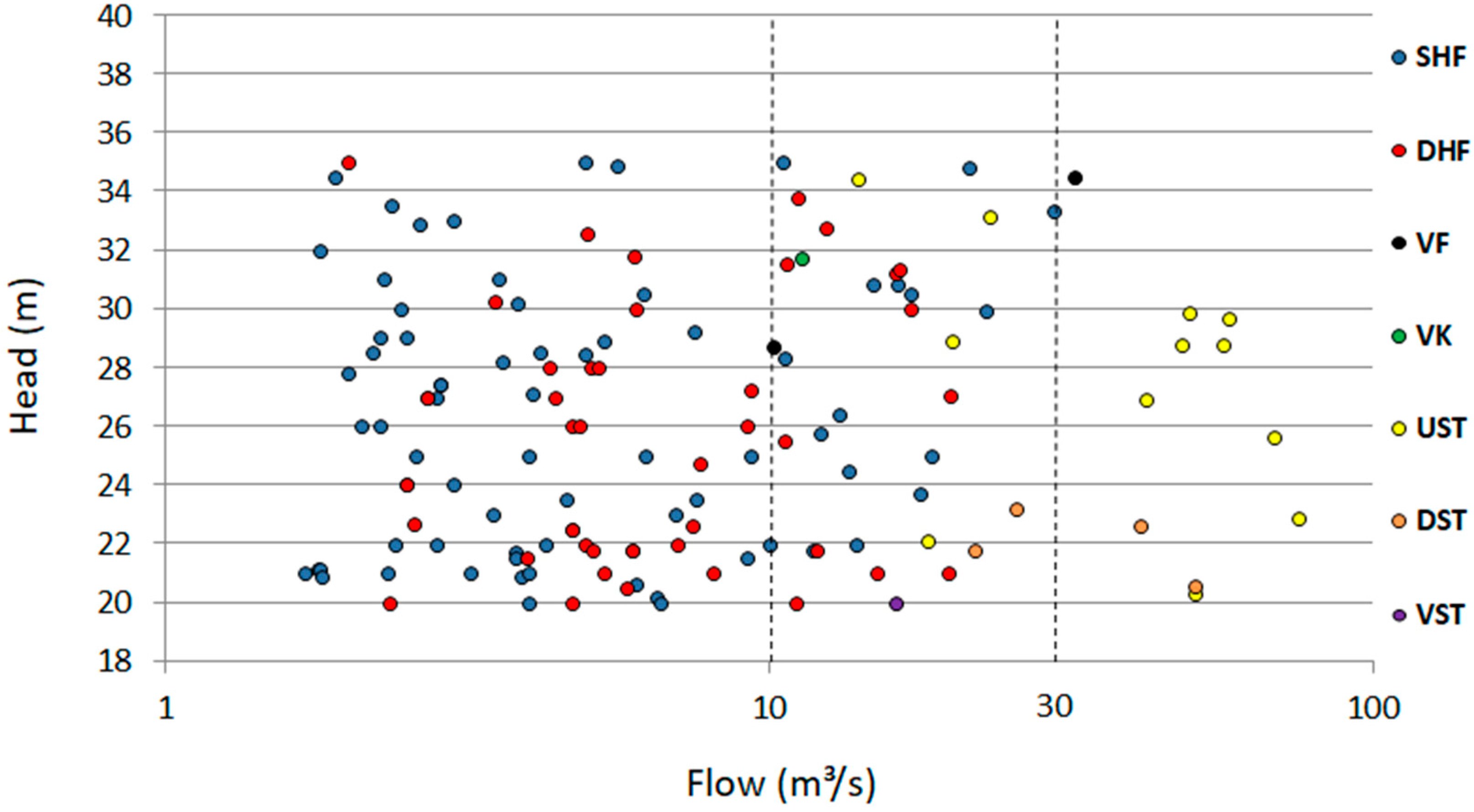
4.2. Phase 2—Step 2.1—Project Characterization

The proposed methodology is applied to a real case study based on a run-of-river SHP project installed in the South of Brazil (Phase 2). The SHP installed capacity is approximately 2.357 MW, with the following technical data: 21.85 m for the net head ( H N ) , 11.8 m3/s for the flow rate ( Q ) , and a nominal turbine speed ( N ) of 360 rpm.

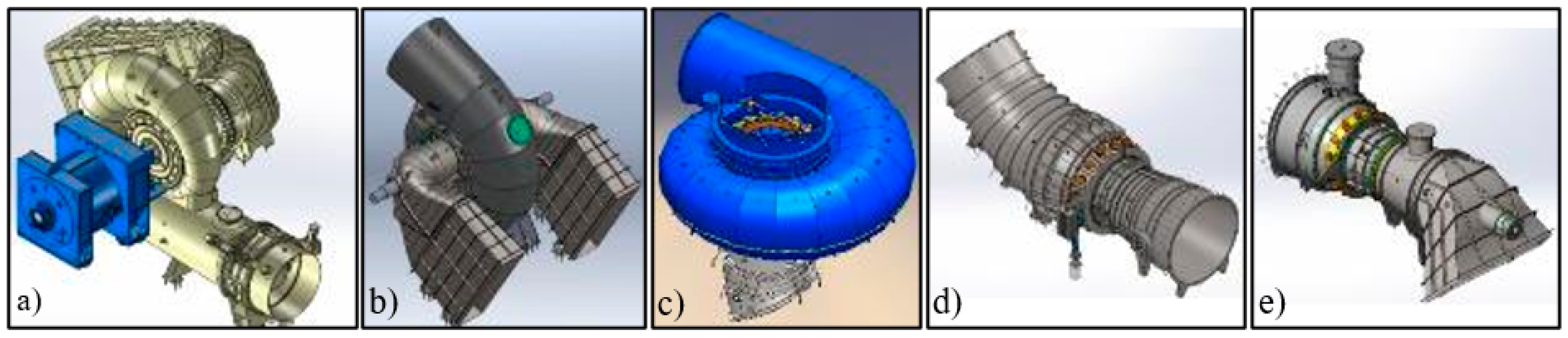
4.3. Phase 2—Step 2.2—Alternatives Selection

Using Equation (2), the turbine’s specific speed is obtained ( N s = 431   rpm ) . Based on the net head and flow rate (Figure 2), it can be determined which turbine category best fits this application (Phase 2—Step 2.2). Francis and Kaplan’s models are found to be best suited considering the rule of thumb. The results are similar when considering the scientific approach (Table 1) in which Francis and Kaplan (including its variants, i.e., tubular, bulb and propeller) models could be selected.
Following the traditional approaches for the PSHT, the decision-maker (e.g., the technical analyst) would select one of the turbines obtained in Step 2.2 according to its experience and preference. Another possibility would be to analyze consumers’ preferences. However, in general, investors are often unaware of the types of available turbines and their particularities. For the case study, it could be chosen Francis or Kaplan family turbines. Francis turbines are more straightforward and usually cheaper than Kaplan turbines. On the other hand, Francis turbines have lower efficiency than Kaplan turbines, as it competes to generate electricity with intermediate flow rates. In this case, the multi-criteria approach becomes a great tool that may support the choice and include the investor’s preferences and other critical criteria in the decision-making process.
The selected alternatives considered during the evaluation process are limited to those hydraulic turbines defined in Step 2.2 (Figure 3). The alternatives comprise the following turbines: SHF, DHF, and VF, with Francis runner; and VK, UST, DST, VST, Bulb, with Kaplan runner (see the intersected area in Figure 2). However, according to the literature review, the VK and Bulb subcategories are usually employed for large hydropower projects. Moreover, typically the VST models have not been used in SHPs. Therefore, these alternatives were subtracted from the main group based on technical requirements and stakeholders’ expertise. Therefore, the selected options (Step 2.2) are illustrated in Figure 5 and comprise (a) SHF, (b) DHF, (c) VF, (d) UST, and (e) DST.
As mentioned in the methodology section, the AHP method establishes the criteria’s weight, while fuzzy-VIKOR is applied to find the most suitable turbine (or turbine group), resulting in the desired compromise solution, as represented in Figure 4.

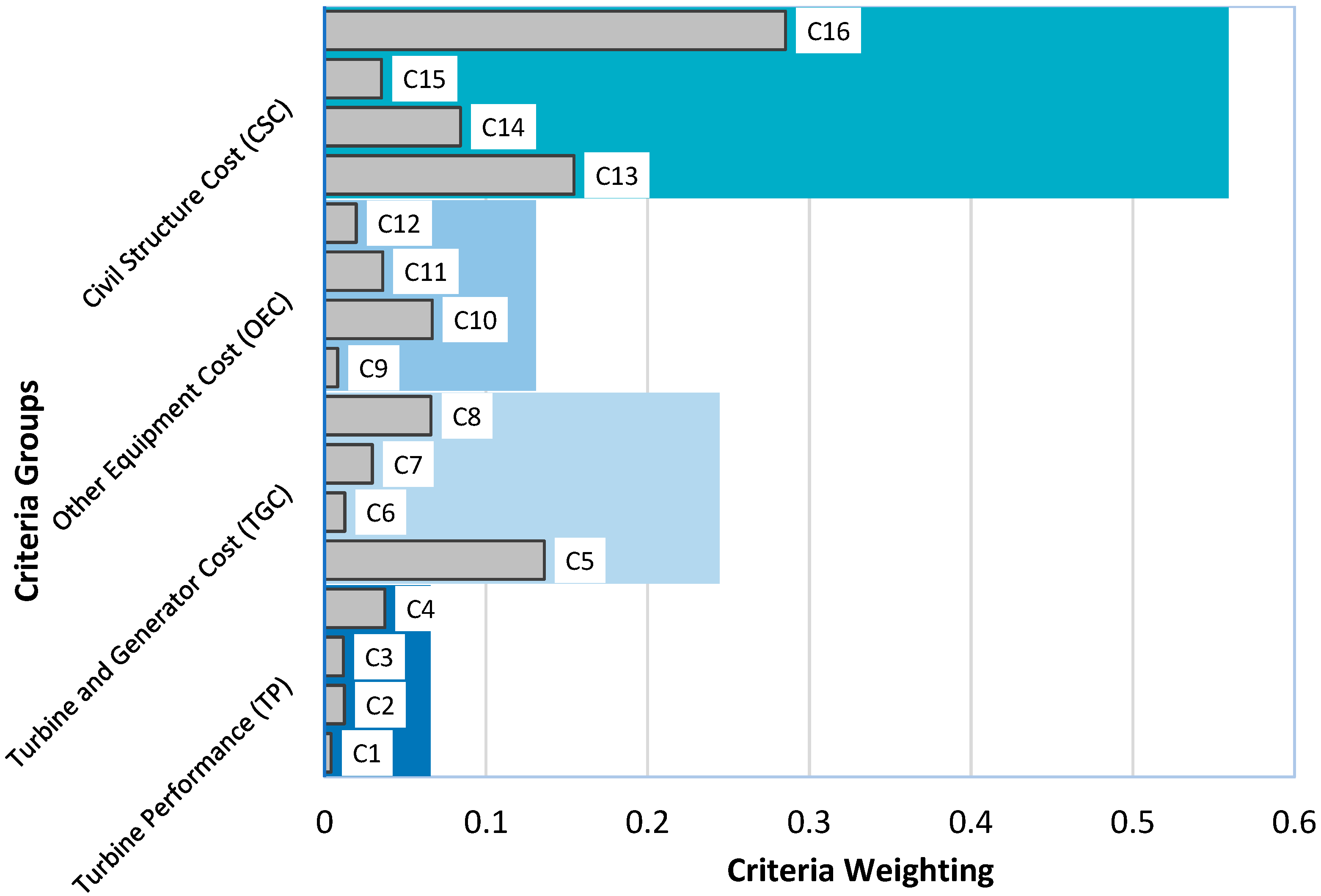
4.4. Phase 3—Step 3.1—Criteria Weighting

The criteria were calculated using the AHP method according to the procedure described in Appendix B. The criteria weights were determined by verifying the investor’s preferences and supported by the project’s technical team, according to Step 3.1 (Phase 3) of Figure 3. The results for the criteria weighting are illustrated in Figure 6. The calculation of the geometrical mean is unnecessary because of the technical team’s consensus. Consequently, the normalization procedure is not necessary in this case. The criteria weighting indicates the relative importance in the category, while the value assigned to each criterion indicates its overall participation, calculated from the fuzzy VIKOR method (Appendix C).
The obtained criteria weighting follows as: TP = 0.0657, TGC = 0.2444, OEC = 0.1308 and CSC = 0.5591. As clearly illustrated in Figure 6, the ‘Civil Structures Cost’ category seems to have higher relative importance, followed by the ‘Turbine and Generator Cost’ and ‘Other Equipment Cost’ categories. The ‘Turbine Performance’ category is found to have smaller importance, which suggests that the cost criteria are more important in this case. From the perspective of investors, the representativeness of each criterion suggests that the cost of structures and equipment is more significant than the equipment’s performance. In other words, even when considering performance over the long term (during the plant’s useful life), the building and acquisition expenditures still emerge as being more significant. These findings support those of Ogayar et al. [82] and Singal et al. [72], who concluded that the turbine-generator set is responsible for 30% of the expenses, whereas the estimated costs for civil works are approximately 40%.

4.5. Phase 3—Step 3.2 and Step 3.3—Alternatives Performance and Compromise Solution

The alternatives evaluation should be carried out in Step 3.2 (Figure 3) to assess the performance of each alternative (A1 = SHF, A2 = DHF, A3 = VF, A4 = UST, and A5 = DST) according to each decision maker (DM) judgment. The judgments of the alternatives were performed by hydraulic turbine experts who have been working in Latin America. Four product engineering specialists were individually interviewed (i.e., DM1, DM2, DM3, and DM4). Table 5 illustrates the results from the expert judgment. The linguistic variables were converted into fuzzy numbers to solve the VIKOR method.
In Step 3.3 (Figure 3), the performance of each alternative is established based on the specialist’s judgment using the m i n l i , m a x r i and the geometric mean for m i , as described in Appendix A (Table A1). The benefits criteria are identified with the symbol (+), while the cost criteria as (-). The distance ‘di’ for each alternative is calculated using Equations (A10) and (A11) (see Table A2). S j   and R j are further calculated using the normalized pondered distance (Equations (A12) and (A13)). The maximum S ,   S ,   R ,   R extracted from Table A3—are shown in Table A4 and represent the fuzzy pondered sum and the maximum fuzzy operator, respectively. These values are necessary to compute each alternative’s fuzzy merit ( Q f ) , as shown in Table A5. The compromise solution is provided by alternatives A1 and A2 (SHF and DHF, respectively) (Table 6).
According to investors’ preferences and expert judgment, SHF and DHF turbines were found as compromise solutions for all scenarios that consider the strategic weights ( v = 0.3 , v = 0.5 , and v = 0.7 ). Therefore, the strategic weights did not influence the results, probably because of the great distance from the first and second alternatives compared to the other alternatives. It is worth mentioning that other solutions could be obtained for other investors’ preferences.
Therefore, the results of this study indicate that SHF and DHF turbine models were considered best suited for the case study under analysis according to the 16 criteria considered. A practical analysis can also be performed by comparing the obtained results with data from a set of installed hydraulic turbines in the country. Data from the largest local manufacturer of hydraulic turbines [91] (Figure 7) is considered, taking into account 135 hydraulic turbines already installed in the last 30 years in SHP projects (with the net head varying between 20 and 35 m). The range of net head was defined based on the shaded region presented in Figure 2.
It can be seen from the data in Figure 7 that historically, the majority of turbines (for the same range of head [20–35 m] and flow rates [10–30 m3/s]) already installed in the country comprises SHF (53%) and DHF (33%). SHF is the most employed turbine in SHP projects in Brazil. Together these turbines represent nearly 86% of the total. Along the same lines, Ref. [92] supports that Francis turbines are the most commonly used turbines for hydroelectric plants in Brazil. Analyzing Figure 7, it can be also noted that near the operating conditions of the case study (i.e., H N = 21.85 m e Q = 11.8 m3/s), there are two DHF turbines and one SHF turbine, which also supports the findings of this research. In this case, the subjective preferences have resembled purely technical decisions, as verified by the technical approach. Taken together, this combination of findings provides some support for the conceptual premise that there is a strong association between experts’ preferences and real-world practices. Therefore, it is likely that such connections exist because the designer’s views are primarily based on cost aspects.
Traditionally, Francis turbines present a more compact layout compared to Kaplan turbines. This research revealed that lower costs with civil structures seem more critical based on investors’ preferences. In general, SHP projects that employ Francis turbines are typically cheaper than Kaplan turbines, even considering that Kaplan turbines usually present higher capacity factors than Francis turbines [23].

5. Conclusions

The preliminary selection of the most suitable hydraulic turbine for a hydropower project has been proven to be not a trivial task and a clearly defined process. Research on the subject has been mostly restricted to limited comparisons of hydraulic turbines and based on empirical evaluation processes, e.g., manufacturer’s recommendations and single expert judgments. For both the practice-based and the scientific-based approaches, the complexities of the hydraulic turbine selection process can be correlated to a series of practical issues, such as the lack of precise information and the wide range of available manufacturers’ catalogs but also depending deeply on the decision maker’s expertise.
Therefore, although the current methods have proven useful, research has consistently shown that the PSHT has been made based on empirical evidence. This process can be adversely affected under certain conditions. Recognizing that the existing approaches may result in sub-optimal results is, therefore, imperative. Bringing to the table the need for a more objective approach to selecting the most suitable hydraulic turbine for a given hydropower project is thus very relevant.
In summary, this research established a robust methodology to support current real-world decision-making problems related to the PSHT. The overall goal of this research lies in the development of a model for the pre-selection of hydraulic turbines through a multicriteria approach, useful for real situations in which the available technical data for the net head and flow rates present a conflict of interest. The framework proposed in this paper not only recognizes the investor’s preferences in the preliminary solution but also integrates other fundamental technical aspects into the decision-making process through an integrated MCDM approach (AHP and fuzzy-VIKOR). A significant advantage of using a MCDM approach is that it allows considering a broader perspective for the investor’s choice and goes beyond the traditional empirical approaches typically employed in the sector.
We systematically reviewed the literature to select the most representative criteria, which were combined into 16 subcriteria, that can be used in future research to evaluate selecting a broad range of hydraulic turbines for hydropower projects. Previous research emphasized the importance of including the efficiency, power, civil structures, portability, modularity, ease of installation, and maintenance and serviceability criteria in the hydraulic turbine’s selection process. Compared to previous studies on the topic, this research increased the perception of essential criteria to be considered for the PSHT.
According to the 16 subcriteria taken into account, the simple horizontal francis (SHF) and double horizontal francis (DHF) turbine models were found to be the most suitable for the case study under analysis. Analyzing existing projects in the region (Brazil), it was found that nearly 86% of the projects employ Francis turbines for the same range of head [20–35 m] and flow rates [10–30 m3/s] (SHF—53% and DHF—33%). These findings clearly indicate the connection between investors’ preferences and local market practices for the case study under analysis. This also suggests that the preliminary project is valid for the executive project since it seems to point to the intended solution. It is worth mentioning that the proposed framework might also support the investor’s preferences in the preliminary stage of the project (PHST). It is worth noting that the results may differ according to the investor’s preferences. Therefore, with the investor’s participation in the decision-making process, the final choice will consider not only the investor’s interest but also other core technical aspects.
Previous studies on typical power applications (i.e., with head [20–35 m] and flow rates [10–30 m3/s]) were found to be scarce, and the most suitable turbine may differ for each project. For example, a method to select a hydro turbine has been proposed by Williamson et al. [30], but with a particular focus on pico hydro turbines for low head sites. The authors of [30] concluded that propeller or single-jet Turgo designs would be more suitable for the particular power applications considered in their study. Adejumobi and Shobayo [28] also dealt with the optimal selection of hydraulic turbines but focused on SHP projects and taking into account a particular net head and flow rate.
The results of the present research can be extended and used in other projects, particularly in the range of net head and flow rates established. Although the case study is focused on a specific head and flow range, projects whose technical data are not included in this range may adopt the same criteria, but the alternatives should be reviewed considering the particular project’s data. The proposed methodological approach proves to be particularly useful if more than one alternative or type of turbine is considered in the application. Therefore, the 16 subcriteria proposed in the present research can be further considered to support the decision-making process for other hydropower projects with different head and flow rates, including SHPs and larger hydropower projects.
The findings of this study make several contributions and policy implications to the current literature and the insights gained may be of assistance to both practitioners and policymakers. Further research should be undertaken, including information regarding the river’s flow curve, which would define the ideal number of generating units, which can also depend on the turbine type.

Author Contributions

Conceptualization, R.C. and D.S.; data curation, R.C. and D.S.; methodology, R.C., D.S. and G.G.D.; validation, R.C. and D.S.; visualization, R.C., D.S. and G.G.D.; formal analysis, R.C. and G.G.D.; writing—original draft preparation, R.C. and G.G.D.; writing—review and editing, G.G.D. and P.F.; supervision, D.S. and P.F. All authors have read and agreed to the published version of the manuscript.

Funding

This work has been supported by FCT – Fundação para a Ciência e Tecnologia within the R&D Units Project Scope: UIDB/00319/2020.

Data Availability Statement

Not applicable.

Conflicts of Interest

The authors declare no conflict of interest.

Abbreviations

The following abbreviations are used in this manuscript:
AHPAnalytical Hierarchy Process
BOCRBenefits, Opportunities, Costs, and Risks
CSCCivil Structures Cost
DHFDouble Horizontal Francis
DMDecision Maker
DSTDownstream S-type
EEMsEnergy Efficiency Measures
ÉLECTREÉLimination Et Choix Traduisant la REalité
FTFrancis Turbine
GHGGreenhouse Gas Emissions
GISGeographic Information Systems
GWGigawatt
HHigh
HPHorizontal Pelton
IECInternational Electrotechnical Commission
KTKaplan Turbines
kWKilowatt
LLow
MMedium
MCDMMulti-Criteria Decision Making
MHMedium High
MLMedium Low
MWMegawatt
NNominal Turbine Speed
NsSpecific Turbine Speed
O&MOperation & Maintenance
OECOther Equipment Cost
PMechanical Power
PTPelton Turbine
PWhPetawatt-hour
PROMETHEEPreference Ranking Organization METHod for Enrichment of Evaluations
PSHTPreliminary Selection of Hydraulic Turbines
RESRenewable Energy Sources
SHFSimple Horizontal Francis
SHPSmall Hydropower Plant
SWOTStrengths, Weaknesses, Opportunities, and Threats
TGCTurbine and Generator Cost
TOPSISTechnique for Order Preference by Similarity to Ideal Solution
TPTurbine Performance
TWhTerawatt-hour
ULHUltra-Low-Head
USTUpstream S-type
VFVertical Francis
VHVery High
VIKORVIseKriterijumska Optimizacija I Kompromisno Resenje
VKVertical Kaplan
VLVery Low
VPVertical Pelton
VSTVertical S-type or Saxo
WSMWeighted Sum Method

Appendix A. Fuzzy-VIKOR Results

Table A1. Aggregation judgments.
CriteriaA1A2A3A4A5
lmrlmrlmrlmrlmr
C1 (+)0.0000.3870.8300.0000.2720.6700.0000.3600.8300.3300.7661.0000.3300.7311.000
C2 (+)0.0000.2720.6700.0000.1820.5000.0000.3010.6700.6700.8301.0000.6700.8301.000
C3 (+)0.3300.6230.8300.1700.4060.6700.3300.6230.8300.6700.8701.0000.6700.8701.000
C4 (+)0.3300.6571.0000.1700.5121.0000.1700.5921.0000.5000.7871.0000.5000.7871.000
C5 (−)0.1700.4700.8300.3300.5790.8300.5000.8241.0000.5000.7071.0000.6700.8701.000
C6 (−)0.0000.1820.5000.0000.2020.6700.1700.4510.6700.1700.5220.8300.1700.5220.830
C7 (−)0.0000.2450.5000.1700.4370.8300.3300.6881.0000.5000.7871.0000.3300.7311.000
C8 (−)0.1700.3940.8300.1700.4370.8300.5000.7871.0000.5000.7811.0000.3300.6881.000
C9 (−)0.0000.2720.6700.0000.3340.6700.5000.7811.0000.3300.6230.8300.5000.7461.000
C10 (−)0.1700.3660.6700.1700.4060.6700.3300.6571.0000.5000.7461.0000.3300.6931.000
C11 (−)0.0000.1820.5000.3300.6571.0000.1700.4700.8300.0000.2240.6700.0000.2240.670
C12 (−)0.0000.1350.5000.0000.1820.5000.1700.4060.6700.1700.4850.8300.0000.3600.830
C13 (−)0.1700.4510.6700.1700.4510.6700.6700.8301.0000.5000.7871.0000.3300.6931.000
C14 (−)0.0000.2720.6700.1700.4060.6700.3300.7261.0000.3300.7261.0000.3300.7261.000
C15 (−)0.1700.3660.6700.1700.4060.6700.5000.8241.0000.5000.7811.0000.3300.6881.000
C16 (−)0.1700.3660.6700.1700.3660.6700.3300.6401.0000.5000.7071.0000.3300.7661.000
Table A2. Distance of the alternatives.
Criteriaƒ*ƒ
lmrlmr
C1 (+)0.3300.7661.0000.0000.2720.670
C2 (+)0.6700.8301.0000.0000.1820.500
C3 (+)0.6700.8701.0000.1700.4060.670
C4 (+)0.5000.7871.0000.1700.5121.000
C5 (−)0.1700.4700.8300.6700.8701.000
C6 (−)0.0000.1820.5000.1700.5220.830
C7 (−)0.0000.2450.5000.5000.7871.000
C8 (−)0.1700.3940.8300.5000.7871.000
C9 (−)0.0000.2720.6700.5000.7811.000
C10 (−)0.1700.3660.6700.5000.7461.000
C11 (−)0.0000.1820.5000.3300.6571.000
C12 (−)0.0000.1350.5000.1700.4850.830
C13 (−)0.1700.4510.6700.6700.8301.000
C14 (−)0.0000.2720.6700.3300.7261.000
C15 (−)0.1700.3660.6700.5000.8241.000
C16 (−)0.1700.3660.6700.5000.7661.000
Table A3. Performance Matrix.
CriteriaA1A2A3A4A5
lmrlmrlmrlmrlmr
Pondered NormalizedC1 (+)−0.0020.0020.004−0.0010.0020.004−0.0020.0020.004−0.0030.0000.003−0.0030.0000.003
C2 (+)0.0000.0070.0120.0020.0080.0120.0000.0070.012−0.0040.0000.004−0.0040.0000.004
C3 (+)−0.0020.0040.0100.0000.0070.012−0.0020.0040.010−0.0050.0000.005−0.0050.0000.005
C4 (+)−0.0230.0060.030−0.0230.0120.037−0.0230.0090.037−0.0230.0000.023−0.0230.0000.023
C5 (−)−0.1080.0000.108−0.0820.0180.108−0.0540.0580.136−0.0540.0390.136−0.0260.0650.136
C6 (−)−0.0080.0000.008−0.0080.0000.010−0.0050.0040.010−0.0050.0050.013−0.0050.0050.013
C7 (−)−0.0150.0000.015−0.0100.0060.025−0.0050.0130.0300.0000.0160.030−0.0050.0140.030
C8 (−)−0.0530.0000.053−0.0530.0030.053−0.0260.0310.066−0.0260.0310.066−0.0400.0230.066
C9 (−)−0.0060.0000.006−0.0060.0010.006−0.0010.0040.008−0.0030.0030.007−0.0010.0040.008
C10 (−)−0.0400.0000.040−0.0400.0030.040−0.0270.0230.067−0.0140.0310.067−0.0270.0260.067
C11 (−)−0.0180.0000.018−0.0060.0170.036−0.0120.0100.030−0.0180.0020.024−0.0180.0020.024
C12 (−)−0.0120.0000.012−0.0120.0010.012−0.0080.0060.016−0.0080.0080.020−0.0120.0050.020
C13 (−)−0.0930.0000.093−0.0930.0000.0930.0000.0710.154−0.0320.0630.154−0.0630.0450.154
C14 (−)−0.0560.0000.056−0.0420.0110.056−0.0290.0380.084−0.0290.0380.084−0.0290.0380.084
C15 (−)−0.0210.0000.021−0.0210.0020.021−0.0070.0200.035−0.0070.0180.035−0.0140.0140.035
C16 (−)−0.1720.0000.172−0.1720.0000.172−0.1170.0940.285−0.0580.1170.285−0.1170.1370.285
Sj−0.6280.0180.657−0.5660.0910.697−0.3180.3940.985−0.2880.3700.955−0.3920.3800.956
Rj0.0000.0070.1720.0020.0180.1720.0000.0940.2850.0000.1170.285−0.0010.1370.285
Table A4. The maximum S ,   S ,   R ,   R .
lmr
S*−0.6280.0180.657
S−0.2880.3940.985
R*−0.0010.0070.172
R0.0020.1370.285
Table A5. Fuzzy merit.
Strategic Weight A1A2A3A4A5
v = 0.5 Qfl−0.698−0.675−0.602−0.593−0.627
m0.0000.0420.2680.3010.340
r0.7010.70131.0000.9910.991
CrispSj0.0160.0790.3640.3520.331
Rj0.0460.0520.1180.1300.140
Qj0.0010.0300.2340.2500.261
v = 0.7 Qfl−0.738−0.708−0603−0.590−0.637
m0.0000.0430.2540.2680.987
r0.7390.7561.0000.9870.987
CrispSj0.0160.0790.3640.3520.331
Rj0.0460.0520.1180.1300.140
Qj0.0000.0340.2260.2330.235
v = 0.3 Qfl−0.659−0.642−0.601−0.595−0.618
m0.0000.0400.2830.3340.386
r0.6620.6701.0000.9940.995
CrispSj0.0160.0790.3640.3520.331
Rj0.0460.0520.1180.1300.267
Qj0.0010.0270.2410.2670.287

Appendix B. The Analytic Hierarchy Process (AHP)

The steps for applying the analytic hierarchy process (AHP) method can be summarized as follows.
Step 1—Experts Decision Matrix: The decision matrix in the AHP method is determined by pairwise comparison of the n elements (criteria) based on an appropriate linguistic/numerical scale (see Table A6).
Table A6. Saaty scale.
Importance IntensitySaaty Original Definition [93]Saaty Complete Definition [94]
1Equal importanceEqual importance
2-Weak importance
3Moderate importance of one over anotherModerate importance
4-Medium importance
5Essential or strong importanceStrong importance
6-Strong plus importance
7Very strong importanceVery strong importance
8-Very, very strong importance
9Extreme importanceExtreme importance
The decision makers assess the relative importance of any two criteria C i and C j by providing a comparison judgment a i j , specifying the extent that C i is preferred/not preferred to C j . If the criteria C i is preferred to C j then a i j > 1 . However, if the criteria are equally preferred, then a i j = 1 and if C j is preferred to C i then a i j < 1 . The a i j (elements located above the main diagonal of the decision matrix) can be obtained by n   ·   ( n 1 ) / 2 comparisons. The elements of the main diagonal are equal to 1. The elements below the main diagonal are reciprocals of the values obtained above the main diagonal, i.e., a i j = 1 / a j i .
Step 2—Prioritization method: The additive normalization method [95] is the procedure used in this paper to obtain the priority vector w of the elements (criteria). Priority vector w is obtained by dividing the elements of each column of the decision matrix by the sum of that column (i.e., to normalize the column). The next step consists of summing up the resulting values in each row and dividing the obtained sum by the number of elements in the row. Equations (A1) and (A2) describe this procedure mathematically.
a i j = a i j / i = j m a i j i , j = 1 ,   2 , , m .
P i = ( 1 / m ) j = 1 m a i j i , j = 1 ,   2 , , m .
where a i j is the element of the decision matrix; a i j is the normalized element of the decision matrix and w j represent the normalized weight of the criterion j.
Step 3—Consistency of the Decision Matrix: The consistency of the priority vector is calculated by using the harmonic consistency index (HCI) as proposed by [96]. HCI is recommended as a consistency measure if the additive normalization method is used, and it can be calculated using Equation (A3).
H C I = [ H M ( s ) n ] · ( n + 1 ) n · ( n 1 )
where HM(s) represents the harmonic mean of the sum of the columns of the comparison matrix and n is the number of elements of the decision matrix.
The division between HCI and the appropriate harmonic random consistency index (HRI) results in the consistency ratio (CR) illustrated in Table A7 and calculated according to Equation (A4).
Table A7. Harmonic Random Consistency Index Matrix [96].
Matrix (n)345678910152025
HRI0.5500.8591.0611.2051.3101.3811.4371.4841.5991.6501.675
H C R = H C I H R I
If a matrix has a CR up to 0.10 (0.05 for n = 3 and 0.08 for n = 4) then the priority vector obtained is sufficiently close to the eigenvector matrix to be consistent [96].
Step 4—Aggregation of the experts’ weights: The aggregation of the weights can then be obtained by using the geometric mean (GM), such as described in Equation (A5), without compromising the reciprocal relationship [97]. The normalization for the average of the judgments can be defined according to Equation (A6).
w ¯ j = k = 1 l ( w j k ) 1 l
w j = = w ¯ j j = 1 m w ¯ j  
where w ¯ j represents the aggregated weight of the criterion j for the l experts and w j = is the aggregated and normalized weight of the criterion j for the l experts.
The procedure described for determining the weights by the AHP method is applied to determine the weights of the groups of criteria and the weight of each criterion within the respective group. The overall weight of all criteria used in the evaluation is obtained using a weighted average.

Appendix C. Fuzzy-VIKOR Method

The VIKOR (VlseKriterijumska Optimizacija I Kompromisno Resenje) method was first introduced by [98], aiming to present a feasible compromise solution through the relationship between criteria and alternatives. Initially, the VIKOR method employed the crisp numbers set. However, as it is relatively complex for the DMs to inform the exact values of alternatives’ judgments, data can be expressed in linguistic terms. Therefore, to model uncertainty in human preferences, fuzzy logic can be successfully applied [98].
The VIKOR mathematical model is presented in detail in the work of [98,99], which includes the group decision aspects extracted from [68]. The essence of the Fuzzy-VIKOR method is given by Equation (A7) (the fuzzy set and fuzzy number definition are illustrated in Appendix A).
m c o j { ( f ˜ i j ( A j ) , j = 1 , , J ) , i = 1 , , n }  
where J is the number of feasible alternatives; A j = { x 1 ,   x 2 ,   } is the jth alternative obtained with specific values of system variables x ; f i j is the value of the criterion function for the alternative A j ; n is the number of criteria; m c o is referencing the operator of a MCDM procedure for selecting the best compromise alternative [99]. The step by step for the VIKOR classification algorithm can be described as follows [99]:
Step 1: Find the ‘best’ f i = ( l i ,   m i ,   r i ) and the ‘worst’ f i = ( l i ,   m i ,   r i ) , being d i j the closest solution to the ideal, with i = 1, 2, …, n . According to Equations (A8) and (A9), the ith function can represent benefit or cost. The m i n l i , m a x r i , and geometrical mean for m i can be employed as the average operators [100].
Benefit   f i = m a x f i j   f i = m i n f i j  
Cos : f i = m i n f i j   f i = m a x f i j    
Step 2: Compute the distances for each alternative, using Equations (A10) and (A11):
B e n e f i t s   d i = ( f i f i j ) ( r i l i )  
C o s t   d i = ( f i j f i ) ( r i l i )
Step 3: Compute the values of the fuzzy pondered sum S j ( S j l , S j m , S j r ) and the maximum fuzzy operator ( R j ) ( R j l , R j m , R j r ) through pondered normalization (and defuzzification) of the distance ( d i ) according to Equations (A12) and (A13), where w i represents the weights of the criteria according to the preference of the DM as the relative importance among the various criteria.
S j = i = 1 n w i   ·   d i
R j = m a x j ( w i · d i )
Step 4: Determinate the values of S ,   S ,   R ,   R , from S j   and R j of the alternatives, where:
S = m i n j S j ,   S = m a x j S j ,
R = m i n j R j ,   R = m a x j R j
Step 5: Compute the values of Fuzzy merit   Q j ( Q j l ,   Q j m ,   Q j r ) for each alternative using Equation (A14):
Q j = v · ( S j S ) ( S S ) + ( 1 v ) · ( R j R ) ( R R )  
where v is the strategic weight of the majority of criteria or the maximum group utility, whereas ( 1 v ) is the individual regret weight, with 0.7 > v > 0.3 . For v = 0.5 , the prioritization is not declared, as the preferences for maximum benefit are considered when v > 0.5 , and those of minimum regret when v < 0.5 .
Step 6: Defuzzification of the values of the   S j , R j and   Q j for each alternative, according to Equation (A15):
C r i s p   ( S j   , R j   ,   Q j ) = ( l + 2 m + r ) 4
Step 7: Classification of the alternatives in descendent order, from   Q j ,   S j and R j , respectively.
Step 8: Definition of the compromise solution, selecting the alternative with the lower   Q j . This solution is determined if two conditions were found to be satisfactory:
Condition 1—Acceptable Advantage, according to Equation (A16):
[ ( Q ( A 2 ) Q ( A 1 ) ) ( Q ( Aj ) Q ( A 1 ) ) ] 1 / ( n 1 )  
Condition 2—Acceptable Stability: The alternative A1 must also be the best classified concerning the   S j and/or   R j .
If one of the conditions is not satisfied, a set of compromise solutions must be proposed, namely:
  • Alternatives A1 and A2 if only Condition 2 is not satisfied.
  • Alternatives A1, A2, …, AM if Condition 1 is not satisfied, with AM given from Equation (A17):
Q ( AM ) Q ( A 1 ) < 1 / ( n 1 )
Finally, a set of alternatives is adopted as a compromise solution that simultaneously satisfies Condition 1 and Condition 2.

References

  1. Pineda, S.; Boomsma, T.K.; Wogrin, S. Renewable Generation Expansion under Different Support Schemes: A Stochastic Equilibrium Approach. Eur. J. Oper. Res. 2018, 266, 1086–1099. [Google Scholar] [CrossRef]
  2. Dranka, G.G.; Ferreira, P. Planning for a Renewable Future in the Brazilian Power System. Energy 2018, 164, 496–511. [Google Scholar] [CrossRef]
  3. IEA (2021), World Energy Outlook 2021, IEA, Paris. Available online: https://www.iea.org/reports/world-energy-outlook-2021 (accessed on 19 July 2020).
  4. IRENA Global Energy Transformation—A Roadmap to 2050. Available online: https://www.irena.org/publications/2018/Apr/Global-Energy-Transition-A-Roadmap-to-2050 (accessed on 19 July 2020).
  5. Dranka, G.G.; Ferreira, P.; Vaz, A.I.F. Cost-Effectiveness of Energy Efficiency Investments for High Renewable Electricity Systems. Energy 2020, 198, 117198. [Google Scholar] [CrossRef]
  6. Bauer, A.; Menrad, K. Standing up for the Paris Agreement: Do Global Climate Targets Influence Individuals’ Greenhouse Gas Emissions? Environ. Sci. Policy 2019, 99, 72–79. [Google Scholar] [CrossRef]
  7. Manglik, M.; Ram, M. Behavioural Analysis of a Hydroelectric Production Power Plant under Reworking Scheme. Int. J. Prod. Res. 2015, 53, 648–664. [Google Scholar] [CrossRef]
  8. Filho, G.L.T.; Santos, I.F.S.D.; Barros, R.M. Cost Estimate of Small Hydroelectric Power Plants Based on the Aspect Factor. Renew. Sustain. Energy Rev. 2017, 77, 229–238. [Google Scholar] [CrossRef]
  9. IHA—International Hydropower Association. 2019 Hydropower Status Report; IHA: London, UK, 2019. [Google Scholar]
  10. Gernaat, D.E.H.J.; Bogaart, P.W.; Vuuren, D.P.V.; Biemans, H.; Niessink, R. High-Resolution Assessment of Global Technical and Economic Hydropower Potential. Nat. Energy 2017, 2, 821–828. [Google Scholar] [CrossRef] [Green Version]
  11. Kumar, R.; Singal, S.K. Selection of Best Operating Site of SHP Plant Based on Performance. Procedia Soc. Behav. Sci. 2015, 189, 110–116. [Google Scholar] [CrossRef] [Green Version]
  12. Breeze, P. Chapter 6—Small Hydropower; Breeze, P.B.T.-H., Ed.; Academic Press: Cambridge, MA, USA, 2018; pp. 53–62. ISBN 978-0-12-812906-7. [Google Scholar]
  13. Balkhair, K.S.; Rahman, K.U. Sustainable and Economical Small-Scale and Low-Head Hydropower Generation: A Promising Alternative Potential Solution for Energy Generation at Local and Regional Scale. Appl. Energy 2017, 188, 378–391. [Google Scholar] [CrossRef]
  14. Özcan, E.C.; Ünlüsoy, S.; Eren, T. A Combined Goal Programming—AHP Approach Supported with TOPSIS for Maintenance Strategy Selection in Hydroelectric Power Plants. Renew. Sustain. Energy Rev. 2017, 78, 1410–1423. [Google Scholar] [CrossRef]
  15. Gono, R.; Novak, M.; Gono, M.; Kyncl, M. Utilization of Small Hydropower. In Proceedings of the 2013 13th International Conference on Environment and Electrical Engineering, EEEIC 2013—Conference Proceedings, Wroclaw, Poland, 1–3 November 2013; pp. 348–351. [Google Scholar]
  16. Borkowski, D. Small Hydropower Plant as a Supplier for the Primary Energy Consumer. In Proceedings of the 2015 16th International Scientific Conference on Electric Power Engineering, EPE 2015, Kouty nad Desnou, Czech Republic, 20–22 May 2015; pp. 148–151. [Google Scholar]
  17. UNIDO—United Nations Industrial Development Organization. World Small Hydropower Development Report 2019; UNIDO: Vienna, Austria, 2019. [Google Scholar]
  18. Ishola, F.A.; Azeta, J.; Agbi, G.; Olatunji, O.O.; Oyawale, F. Simulation for Material Selection for a Pico Pelton Turbine’s Wheel and Buckets. Procedia Manuf. 2019, 35, 1172–1177. [Google Scholar] [CrossRef]
  19. Xu, B.; Chen, D.; Li, H.; Zhuang, K.; Hu, X.; Li, J.; Skjelbred, H.I.; Kong, J.; Patelli, E. Priority Analysis for Risk Factors of Equipment in a Hydraulic Turbine Generator Unit. J. Loss Prev. Process Ind. 2019, 58, 1–7. [Google Scholar] [CrossRef]
  20. Kougias, I.; Aggidis, G.; Avellan, F.; Deniz, S.; Lundin, U.; Moro, A.; Muntean, S.; Novara, D.; Pérez-Díaz, J.I.; Quaranta, E.; et al. Analysis of Emerging Technologies in the Hydropower Sector. Renew. Sustain. Energy Rev. 2019, 113, 109257. [Google Scholar] [CrossRef]
  21. Tamm, O.; Tamm, T. Verification of a Robust Method for Sizing and Siting the Small Hydropower Run-of-River Plant Potential by Using GIS. Renew. Energy 2020, 155, 153–159. [Google Scholar] [CrossRef]
  22. Zhou, D.; Deng, Z. (Daniel) Ultra-Low-Head Hydroelectric Technology: A Review. Renew. Sustain. Energy Rev. 2017, 78, 23–30. [Google Scholar] [CrossRef]
  23. Ibrahim, M.; Imam, Y.; Ghanem, A. Optimal Planning and Design of Run-of-River Hydroelectric Power Projects. Renew. Energy 2019, 141, 858–873. [Google Scholar] [CrossRef]
  24. Yildiz, V. Numerical Simulation Model of Run of River Hydropower Plants: Concepts, Numerical Modeling, Turbine System and Selection, and Design Optimization; University of California: Oakland, CA, USA, 2015. [Google Scholar]
  25. Nasir, B.A. Design Considerations of Micro-Hydro-Electric Power Plant. Energy Procedia 2014, 50, 19–29. [Google Scholar] [CrossRef]
  26. Elbatran, A.H.; Yaakob, O.B.; Ahmed, Y.M.; Shabara, H.M. Operation, Performance and Economic Analysis of Low Head Micro-Hydropower Turbines for Rural and Remote Areas: A Review. Renew. Sustain. Energy Rev. 2015, 43, 40–50. [Google Scholar] [CrossRef]
  27. Sangal, S.; Garg, A.; Kumar, D. Review of Optimal Selection of Turbines for Hydroelectric Projects. Int. J. Emerg. Technol. Adv. Eng. 2013, 3, 424–430. [Google Scholar]
  28. Adejumobi, I.; Shobayo, D. Optimal Selection of Hydraulic Turbines for Small Hydro Electric Power Generation—A Case Study of Opeki River, South Western Nigeria. Niger. J. Technol. 2015, 34, 530. [Google Scholar] [CrossRef]
  29. Williams, A.A.; Upadhyay, D.R. Low Head Pico Hydropower: A Review of Available Turbine Technologies. In World Renewable Energy Congress VI (WREC2000); Pergamon Press: Amsterdam, The Netherlands, 2000; pp. 1745–1750. [Google Scholar] [CrossRef]
  30. Williamson, S.J.; Stark, B.H.; Booker, J.D. Low Head Pico Hydro Turbine Selection Using a Multi-Criteria Analysis. Renew. Energy 2014, 61, 43–50. [Google Scholar] [CrossRef]
  31. Alterach, J.; Popa, B.; Magureanu, R.; Šantl, S.; Kozelj, D.; Rak, G.; Skroza, A.; Steinman, F.; Zenz, G.; Harb, G.; et al. Manual Addressed to Stakeholders with the Description of Methodologies to Improve SHP Implementation in SEE Countries; See Hydopower: Milano, Italy, 2010. [Google Scholar]
  32. Singal, S. Planning and Implementation of Small Hydropower (SHP) Projects. Hydro. Nepal. J. Water Energy 2009, 5, 21–25. [Google Scholar] [CrossRef]
  33. Zhou, J.X.; Hu, M.; Cai, F.L.; Huang, X.T. Effects of Turbine’s Selection on Hydraulic Transients in the Long Pressurized Water Conveyance System. In IOP Conference Series: Earth and Environmental Science; IOP Publishing: Bristol, UK, 2014; Volume 22. [Google Scholar]
  34. Govindan, K.; Kannan, D.; Shankar, M. Evaluation of Green Manufacturing Practices Using a Hybrid MCDM Model Combining DANP with PROMETHEE. Int. J. Prod. Res. 2015, 53, 6344–6371. [Google Scholar] [CrossRef]
  35. Yadav, G.; Mangla, S.K.; Luthra, S.; Jakhar, S. Hybrid BWM-ELECTRE-Based Decision Framework for Effective Offshore Outsourcing Adoption: A Case Study. Int. J. Prod. Res. 2018, 56, 6259–6278. [Google Scholar] [CrossRef] [Green Version]
  36. Irawan, C.A.; Akbari, N.; Jones, D.F.; Menachof, D. A Combined Supply Chain Optimisation Model for the Installation Phase of Offshore Wind Projects. Int. J. Prod. Res. 2018, 56, 1189–1207. [Google Scholar] [CrossRef] [Green Version]
  37. Bai, C.; Kusi-Sarpong, S.; Badri Ahmadi, H.; Sarkis, J. Social Sustainable Supplier Evaluation and Selection: A Group Decision-Support Approach. Int. J. Prod. Res. 2019, 57, 7046–7067. [Google Scholar] [CrossRef]
  38. Mahapatra, D.; Katiyar, R.; Parida, R.; Kumar, D. A Fuzzy Multi-Criteria Approach for Evaluating the Contribution of Freight Transportation towards India’s Nationally Determined Contributions (NDCs). Int. J. Prod. Res. 2021, 59, 2857–2884. [Google Scholar] [CrossRef]
  39. Laghari, J.A.; Mokhlis, H.; Bakar, A.H.A.; Mohammad, H. A Comprehensive Overview of New Designs in the Hydraulic, Electrical Equipments and Controllers of Mini Hydro Power Plants Making It Cost Effective Technology. Renew. Sustain. Energy Rev. 2013, 20, 279–293. [Google Scholar] [CrossRef]
  40. Paish, O. Small Hydro Power: Technology and Current Status. Renew. Sustain. Energy Rev. 2002, 6, 537–556. [Google Scholar] [CrossRef]
  41. IEC. IEC/TR 61364:1999—Nomenclature for Hydroelectric Powerplant Machinery; IEC: Geneva, Switzerland, 1999. [Google Scholar]
  42. Gale, J.; Höfler, E.; Bergant, A. Compact Vertical Axial Turbine “Saxo”. In Proceedings of the 16th Intern Seminar on Hydropower Plants, Viena, Austria, 24–26 November 2010; p. 10. [Google Scholar]
  43. Yaseen, Z.M.; Ameen, A.M.S.; Aldlemy, M.S.; Ali, M.; Afan, H.A.; Zhu, S.; Al-Janabi, A.M.S.; Al-Ansari, N.; Tiyasha, T.; Tao, H. State-of-the Art-Powerhouse, Dam Structure, and Turbine Operation and Vibrations. Sustainability 2020, 12, 1676. [Google Scholar] [CrossRef]
  44. Kaunda, C.S.; Kimambo, C.Z.; Nielsen, T.K. A Technical Discussion on Microhydropower Technology and Its Turbines. Renew. Sustain. Energy Rev. 2014, 35, 445–459. [Google Scholar] [CrossRef]
  45. Uhunmwangho, R.; Odje, M.; Okedu, K.E. Comparative Analysis of Mini Hydro Turbines for Bumaji Stream, Boki, Cross River State, Nigeria. Sustain. Energy Technol. Assess. 2018, 27, 102–108. [Google Scholar] [CrossRef]
  46. WEG Group—Energy Business Unit Energia—Turbinas Hidráulicas. Available online:https://static.weg.net/medias/downloadcenter/he5/h76/WEG-turbinas-hidraulicas-50083024-catalogo-portugues.pdf (accessed on 21 November 2020).
  47. Singal, S.K.; Saini, R.P. Analytical Approach for Development of Correlations for Cost of Canal-Based SHP Schemes. Renew. Energy 2008, 33, 2549–2558. [Google Scholar] [CrossRef]
  48. Macintyre, A.J. Máquinas Motrizes Hidráulicas; Guanabara Dois: Rio de Janeiro, Brasil, 1983; ISBN 85-7030-016-6. [Google Scholar]
  49. Raabe, J. Hydro PowerDesing, Use, and Function of Hydromechanical Hydraulic and Electrical Equipament; VDI-Verlag GmbH: Würzburg, Germany, 1985; ISBN 3-18-400616-6. [Google Scholar]
  50. Mardani, A.; Jusoh, A.; Nor, K.M.; Khalifah, Z.; Zakwan, N.; Valipour, A. Multiple Criteria Decision-Making Techniques and Their Applications—A Review of the Literature from 2000 to 2014. Econ. Res. Ekon. Istraživanja 2015, 28, 516–571. [Google Scholar] [CrossRef]
  51. Strantzali, E.; Aravossis, K. Decision Making in Renewable Energy Investments: A Review. Renew. Sustain. Energy Rev. 2016, 55, 885–898. [Google Scholar] [CrossRef]
  52. Suganthi, L.; Iniyan, S.; Samuel, A.A. Applications of Fuzzy Logic in Renewable Energy Systems—A Review. Renew. Sustain. Energy Rev. 2015, 48, 585–607. [Google Scholar] [CrossRef]
  53. Siksnelyte, I.; Zavadskas, E.K.; Streimikiene, D.; Sharma, D. An Overview of Multi-Criteria Decision-Making Methods in Dealing with Sustainable Energy Development Issues. Energies 2018, 11, 2754. [Google Scholar] [CrossRef] [Green Version]
  54. Kaya, T.; Kahraman, C. Multicriteria Renewable Energy Planning Using an Integrated Fuzzy VIKOR & AHP Methodology: The Case of Istanbul. Energy 2010, 35, 2517–2527. [Google Scholar] [CrossRef]
  55. Lee, H.C.; Chang, C. ter Comparative Analysis of MCDM Methods for Ranking Renewable Energy Sources in Taiwan. Renew. Sustain. Energy Rev. 2018, 92, 883–896. [Google Scholar] [CrossRef]
  56. Kabak, M.; Daǧdeviren, M. Prioritization of Renewable Energy Sources for Turkey by Using a Hybrid MCDM Methodology. Energy Convers. Manag. 2014, 79, 25–33. [Google Scholar] [CrossRef]
  57. Tasri, A.; Susilawati, A. Selection among Renewable Energy Alternatives Based on a Fuzzy Analytic Hierarchy Process in Indonesia. Sustain. Energy Technol. Assess. 2014, 7, 34–44. [Google Scholar] [CrossRef]
  58. Solangi, Y.A.; Tan, Q.; Mirjat, N.H.; Ali, S. Evaluating the Strategies for Sustainable Energy Planning in Pakistan: An Integrated SWOT-AHP and Fuzzy-TOPSIS Approach. J. Clean Prod. 2019, 236, 117655. [Google Scholar] [CrossRef]
  59. Wang, Y.; Xu, L.; Solangi, Y.A. Strategic Renewable Energy Resources Selection for Pakistan: Based on SWOT-Fuzzy AHP Approach. Sustain. Cities Soc. 2019, 52, 101861. [Google Scholar] [CrossRef]
  60. Supriyasilp, T.; Pongput, K.; Boonyasirikul, T. Hydropower Development Priority Using MCDM Method. Energy Policy 2009, 37, 1866–1875. [Google Scholar] [CrossRef]
  61. Rosso, M.; Bottero, M.; Pomarico, S.; Ferlita, S.L.; Comino, E. Integrating Multicriteria Evaluation and Stakeholders Analysis for Assessing Hydropower Projects. Energy Policy 2014, 67, 870–881. [Google Scholar] [CrossRef]
  62. Kumar, R.; Singal, S.K. Penstock Material Selection in Small Hydropower Plants Using MADM Methods. Renew. Sustain. Energy Rev. 2015, 52, 240–255. [Google Scholar] [CrossRef]
  63. Majumder, P.; Majumder, M.; Saha, A.K.; Nath, S. Selection of Features for Analysis of Reliability of Performance in Hydropower Plants: A Multi-Criteria Decision Making Approach. Environ. Dev. Sustain. 2019, 22, 3239–3265. [Google Scholar] [CrossRef]
  64. Adhikary, P.; Kundu, S.; Roy, P.K.; Mazumdar, A. Optimum Selection of Hydraulic Turbine Manufacturer for SHP:MCDA or MCDM Tools. World Appl. Sci. J. 2013, 28, 914–919. [Google Scholar] [CrossRef]
  65. International Electrotechnical Commission IEC. In 61116:1992—Electromechanical Equipment Guide for Small Hydroelectric Installations; IEC: Geneva, Switzerland, 1992; p. 102.
  66. Ensslin, L.; Lacerda, R.T.O.; Tasca, J.E. ProKnow-C, Knowledge Development Process—Constructivist. Técnico Com Pat. Regist. Pendente Junto INPI 2010, 10, 2015. [Google Scholar]
  67. Goodman, L.A. Snowball Sampling. Ann. Math. Stat. 1961, 32, 148–170. [Google Scholar] [CrossRef]
  68. Wu, Z.; Ahmad, J.; Xu, J. A Group Decision Making Framework Based on Fuzzy VIKOR Approach for Machine Tool Selection with Linguistic Information. Appl. Soft Comput. J. 2016, 42, 314–324. [Google Scholar] [CrossRef]
  69. Mishra, S.; Singal, S.K.; Khatod, D.K. A Review on Electromechanical Equipment Applicable to Small Hydropower Plants. Int. J. Energy Res. 2012, 4, 553–571. [Google Scholar] [CrossRef]
  70. Hatata, A.Y.; El-Saadawi, M.M.; Saad, S. A Feasibility Study of Small Hydro Power for Selected Locations in Egypt. Energy Strategy Rev. 2019, 24, 300–313. [Google Scholar] [CrossRef]
  71. Alexander, K.V.; Giddens, E.P. Microhydro: Cost-Effective, Modular Systems for Low Heads. Renew. Energy 2008, 33, 1379–1391. [Google Scholar] [CrossRef]
  72. Singal, S.K.; Saini, R.P.; Raghuvanshi, C.S. Analysis for Cost Estimation of Low Head Run-of-River Small Hydropower Schemes. Energy Sustain. Dev. 2010, 14, 117–126. [Google Scholar] [CrossRef]
  73. Mishra, S.; Singal, S.K.; Khatod, D.K. Optimal Installation of Small Hydropower Plant—A Review. Renew. Sustain. Energy Rev. 2011, 15, 3862–3869. [Google Scholar] [CrossRef]
  74. Tuna, M.C. Feasibility Assessment of Hydroelectric Power Plant in Ungauged River Basin: A Case Study. Arab. J. Sci. Eng. 2013, 38, 1359–1367. [Google Scholar] [CrossRef] [Green Version]
  75. Mishra, S.; Singal, S.K.; Khatod, D.K. Cost Analysis for Electromechanical Equipment in Small Hydropower Projects. Int. J. Green Energy 2013, 10, 835–847. [Google Scholar] [CrossRef]
  76. Okot, D.K. Review of Small Hydropower Technology. Renew. Sustain. Energy Rev. 2013, 26, 515–520. [Google Scholar] [CrossRef]
  77. Gagliano, A.; Tina, G.M.; Nocera, F.; Patania, F. Technical and Economic Perspective for Repowering of Micro Hydro Power Plants: A Case Study of an Early XX Century Power Plant. Energy Procedia 2014, 62, 512–521. [Google Scholar] [CrossRef] [Green Version]
  78. Loots, I.; Van Dijk, M.; Barta, B.; Van Vuuren, S.J.; Bhagwan, J.N. A Review of Low Head Hydropower Technologies and Applications in a South African Context. Renew. Sustain. Energy Rev. 2015, 50, 1254–1268. [Google Scholar] [CrossRef]
  79. Ak, M.; Kentel, E.; Kucukali, S. A Fuzzy Logic Tool to Evaluate Low-Head Hydropower Technologies at the Outlet of Wastewater Treatment Plants. Renew. Sustain. Energy Rev. 2017, 68, 727–737. [Google Scholar] [CrossRef]
  80. Mandelli, S.; Colombo, E.; Redondi, A.; Bernardi, F.; Saanane, B.B.; Mgaya, P.; Malisa, J. A Small-Hydro Plant Model for Feasibility Analysis of Electrification Projects in Rural Tanzania. In Proceedings of the 2013 IEEE Global Humanitarian Technology Conference (GHTC), San Jose, CA, USA, 20–23 October 2013; pp. 11–16. [Google Scholar]
  81. Forouzbakhsh, F.; Hosseini, S.M.H.; Vakilian, M. An Approach to the Investment Analysis of Small and Medium Hydro-Power Plants. Energy Policy 2007, 35, 1013–1024. [Google Scholar] [CrossRef] [Green Version]
  82. Ogayar, B.; Vidal, P.G. Cost Determination of the Electro-Mechanical Equipment of a Small Hydro-Power Plant. Renew. Energy 2009, 34, 6–13. [Google Scholar] [CrossRef]
  83. Guo, P.; Wang, Z.; Sun, L.; Luo, X. Characteristic Analysis of the Efficiency Hill Chart of Francis Turbine for Different Water Heads. Adv. Mech. Eng. 2017, 9, 1–8. [Google Scholar] [CrossRef]
  84. Anagnostopoulos, J.S.; Papantonis, D.E. Optimal Sizing of a Run-of-River Small Hydropower Plant. Energy Convers. Manag. 2007, 48, 2663–2670. [Google Scholar] [CrossRef]
  85. Kumar, R.; Singal, S.K. Operation and Maintenance Problems in Hydro Turbine Material in Small Hydro Power Plant. Mater. Today Proc. 2015, 2, 2323–2331. [Google Scholar] [CrossRef]
  86. Singh, V.K.; Singal, S.K. Operation of Hydro Power Plants-a Review. Renew. Sustain. Energy Rev. 2017, 69, 610–619. [Google Scholar] [CrossRef]
  87. Dinkar, P.S.; Morankar, D.V. Performance Evaluation of Small Hydropowe Projects in Maharashtra. Int. J. Adv. Eng. Technol 2015, 8, 551–558. [Google Scholar]
  88. Thapar, O.D. Modern Hydroelectric Engineering Practice in India: Electro-Mechanical Works; Alternate Hydro Energy Centre: Roorkee, Índia, 2002. [Google Scholar]
  89. Sur, S.K. A Practical Guide to Construction of Hydropower Facilities, 1st ed.; CRC Press: New York, NY, USA, 2019; ISBN 9780815378051. [Google Scholar]
  90. Singal, S.K.; Saini, R.P.; Raghuvanshi, C.S. Cost Optimisation Based on Electro-Mechanical Equipment of Canal Based Low Head Small Hydropower Scheme. Open Renew. Energy J. 2014, 1, 26–35. [Google Scholar] [CrossRef] [Green Version]
  91. WEG Group—Energy Business Unit Types of Hydraulic Turbines Installed Based on Head and Flow—Internal WEG Report 2019, unpublished.
  92. Kim, S.J.; Choi, Y.S.; Cho, Y.; Choi, J.W.; Kim, J.H. Effect of Blade Thickness on the Hydraulic Performance of a Francis Hydro Turbine Model. Renew. Energy 2019, 134, 807–817. [Google Scholar] [CrossRef]
  93. Saaty, T. How to Make a Decision The Analytic Hierarchy Process. Eur. J. Oper. Res. 1990, 48, 19–43. [Google Scholar] [CrossRef]
  94. Saaty, T.L. Decision Making with the Analytic Hierarchy Process. Int. J. Serv. Sci. 2008, 1, 83–98. [Google Scholar] [CrossRef] [Green Version]
  95. Srdjevic, B. Combining Different Prioritization Methods in the Analytic Hierarchy Process Synthesis. Comput Oper. Res. 2005, 32, 1897–1919. [Google Scholar] [CrossRef]
  96. Stein, W.E.; Mizzi, P.J. The Harmonic Consistency Index for the Analytic Hierarchy Process. Eur. J. Oper. Res. 2007, 177, 488–497. [Google Scholar] [CrossRef]
  97. Ishizaka, A.; Labib, A. Review of the Main Developments in the Analytic Hierarchy Process. Expert Syst. Appl. 2011, 38, 14336–14345. [Google Scholar] [CrossRef] [Green Version]
  98. Opricovic, S.; Tzeng, G.H. Compromise Solution by MCDM Methods: A Comparative Analysis of VIKOR and TOPSIS. Eur. J. Oper. Res. 2004, 156, 445–455. [Google Scholar] [CrossRef]
  99. Opricovic, S. Fuzzy VIKOR with an Application to Water Resources Planning. Expert Syst. Appl. 2011, 38, 12983–12990. [Google Scholar] [CrossRef]
  100. Vaníček, J.; Vrana, I.; Aly, S. Fuzzy Aggregation and Averaging for Group Decision Making: A Generalization and Survey. Knowl. Based Syst. 2009, 22, 79–84. [Google Scholar] [CrossRef]
Figure 1. Main stages in the development of a small hydropower project (Adapted from [31]).
Energies 15 07383 g001
Figure 2. Typical application ranges based on the practice-based approach for turbine selection [46].
Energies 15 07383 g002
Figure 3. General methodological approach.
Energies 15 07383 g003
Figure 4. Application of MCDM (AHP and fuzzy-VIKOR) (Phase 3).
Energies 15 07383 g004
Figure 5. Selected possible hydraulic turbines for the case study: (a) SHF; (b) DHF; (c) VF; (d) UST; (e) DST.
Energies 15 07383 g005
Figure 6. Criteria Weighting.
Energies 15 07383 g006
Figure 7. Dispersion of installed hydraulic turbines based on head and flow rate (Brazil) [91].
Energies 15 07383 g007
Table 1. Classical hydraulic turbines based on the specific speed N s [48,49].
Type of Turbine
N s   ( rpm )
Pelton18–90
Francis55–450
Kaplan/Tubular/Bulb/Propeller250–1350
Table 2. Linguistic variables established based on Ref. [68].
ClassificationLinguistic VariableTriangular Fuzzy Number
Very LowVL(0; 0; 0.17)
LowL(0; 0.17; 0.33)
Medium LowML(0.17; 0.33; 0.5)
MediumM(0.33; 0.5; 0.67)
Medium-HighMH(0.5; 0.67; 0.83)
HighH(0.67; 0.83; 1)
Very HighVH(0.83; 1.00; 1)
Table 3. Categories traditionally considered by previous research in the design of SHP projects.
ReferenceTurbine and GeneratorMechanical and Electrical Auxiliary SystemsHydromechanical EquipmentPenstockPowerhouseOperation & Maintenance (O&M)
Mishra et al. [69]
Hatata et al. [70]
Alexander and Giddens [71]
Singal et al. [72]
Mishra et al. [73]
Tuna [74]
Mishra et al. [75]
Okot [76]
Gagliano et al. [77]
Loots et al. [78]
Ak et al. [79]
Mandelli et al. [80]
Forouzbakhsh et al. (2007) [81]
Ogayar and Vidal [82]
Total1399111213
Table 4. Categories and criteria description.
IDCategoriesCriteriaCost/BenefitDescription
C1Turbine Performance
(TP)
Net head variationThe higher, the betterSome turbines can operate in a wide range of water-head variations. Therefore, a wider operating range on the hill chart is preferable [83].
C2Flow rate variationThe higher, the betterA turbine that accepts a broader flow rate variation has a higher probability of operating for extended periods, such as in the case of drought conditions when the flow rate is reduced [83].
C3EfficiencyThe higher, the betterAn important variable to compare different turbine types is their relative efficiencies for nominal and reduced flow rates. Generally, different from Francis and propeller turbines, the Pelton, Crossflow, and Kaplan turbines retain higher efficiencies when running below the designed flow rate [40,84].
C4ReliabilityThe higher, the betterAfter some years of operation, hydraulic turbines’ performance and efficiency might decrease because of several factors, including cavitation, erosion, fatigue, and material defects [85]. For example, some hydraulic turbines are more prone to erosion and cavitation wear (e.g., Francis turbines).
C5Turbine and Generator Cost
(TGC)
Turbine and Generator Investment CostThe lower, the betterIt represents one of the highest costs of the SHPs, and it can reach levels higher than 30% of the overall project’s cost [82].
C6Turbine Operating CostThe lower, the betterA SHP has a proper operation when extracting the maximum energy from the available potential at minimum operating costs [86]. Modular turbines equipped with non-complex systems and nationalized components are cheaper.
C7Turbine and Generator Maintenance CostThe lower, the betterIt is associated with the serviceability of both the turbine and generator. The maintenance costs represent a substantial amount of the overall annual costs [87].
C8Turbine Non-availability CostThe lower, the betterThe purpose of a SHP is to sell electricity continuously. Therefore, the turbine’s non-availability might bring financial losses for the company and should be avoided [14].
C9Other Equipment Cost
(OEC)
Electric Overhead Traveling (EOT) Cranes CostThe lower, the betterIt comprises cranes for the powerhouse, intake, and tailrace. These devices are necessary for O&M due to the load-lifting capacities, which depend on the SHP layout, turbine weight, generator, hydromechanical components, and the O&M strategy. Our review found that previous research has traditionally neglected the cost associated with this equipment.
C10Hydromechanical Equipment CostThe lower, the betterThis cost includes the ones related to the gates, valves, trash racks, and other small equipment. The turbine type might also interfere with hydromechanical equipment, whose hydraulic transients may require more robust equipment [33].
C11Penstock CostThe lower, the betterThe penstock’s dimensions depend on the general layout of the power plant and the size and type of the turbine. Therefore, it has been traditionally considered acquisition, installation, and maintenance costs [62].
C12Auxiliary Systems CostThe lower, the betterElectrical and mechanical auxiliaries’ systems are considered secondary equipment but vital for operation and safety concerns. Depending on the turbine type, more robust auxiliary systems are required (e.g., Kaplan and Pelton turbines) [88,89].
C13Civil Structures Cost
(CSC)
Powerhouse Excavation CostThe lower, the betterDepending on the turbine’s size, it might be required larger powerhouses. Consequently, it might also need a greater excavation volume. Additionally, the setting of turbine installation might require extensive excavation.
C14Substructure CostThe lower, the betterThe substructure is usually built using concrete and reinforced with steel when necessary. This depends on the turbine’s size and the efforts transmitted to the structure.
C15Super-Structure CostThe lower, the betterIt can be constructed as a steel structure consisting of columns, beams, roofing trusses, roof, railings, gates, and trash racks. It can also be reinforced by a concrete framed structure [90]. This structure supports the cranes, whose capacity depends on the turbine type. The structure’s size depends on the powerhouse’s dimensions, which are also related to the size of the turbine.
C16Dam and Intake CostThe lower, the betterThe dam is considered one of the largest structures in a power plant, responsible for storing the water. It typically supports the spillway and its respective mechanical and auxiliary drive equipment. In some cases, it also includes water intake and other equipment. The penstock is connected to the intake. Thus, the outlet structure should consider the penstock dimensions, which are associated with the type of turbine.
Table 5. Fuzzy classification of the alternatives.
DM1DM2DM3DM4
A1A2A3A4A5A1A2A3A4A5A1A2A3A4A5A1A2A3A4A5
C1LLLHHMHMLMVHVHMHMMHMMMMLMHH
C2LLLHHMLLMLHHMLMLMHHMMLMHH
C3MHMMHHHMHMLMHVHVHMHMMHHHMMLMHH
C4HHHHHMHMMHHHMMMHMHMHMHMLMLHH
C5MHMHHMHHMHMHVHMHHMLMHHVHMLMMHMHH
C6LLMLMLMLMLMLMMHMHLLMMMMLMMMHMH
C7MLMLMHMHMMLMLMHHHLMVHHHMLMHMHH
C8MLMLHHMMHMHHVHVHMLMLMHMHMHMLMHMHMH
C9MMVHMHMHLLMHMMHMLMHMHHMLMMHMHH
C10MLMLMHMHMMLMLMMHMHMMHHHMLMMHHH
C11LMHMLLLLMHMHMMMLMMHMMMLHMLLL
C12LLMLMLLMLMLMMHMHLLMMMLMLMLMM
C13MMHHMMMLHVHHMMHHHMLMHMHMH
C14LMLMHMMMMHHHMLMVHVHVHMLMLMMHMH
C15MLMLHHMMMMHMHMHMLMLVHVHVHMLMHMHMH
C16MLMLMMHMMLMLMMHMHMMVHHVHMLMLMHMHH
Table 6. Compromise solution between alternatives.
Strategic Weight 1ConditionAlternative A1 (SHF)Alternative A2 (DHF)
v = 0.5 Condition 1 ≥ 0.25Not Accept
(Condition 1 = 0.1115)
Accept
(Condition 1 = 0.8831)
Condition 2-Accept
v = 0.7 Condition 1 ≥ 0.25Not Accept
(Condition 1 = 0.1447)
Accept
(Condition 1 = 0.9552)
Condition 2-Accept
v = 0.3 Condition 1 ≥ 0.25Not Accept
(Condition 1 = 0.0909)
Accept
(Condition 1 = 0.8231)
Condition 2-Accept
1 The case study will also address the verification of the selection strategy ( v ) for the following scenarios: prioritization of benefits ( v = 0.7 ), minimization of losses related to the choice ( v = 0.3 ), and undeclared prioritization ( v = 0.5 ).
Publisher’s Note: MDPI stays neutral with regard to jurisdictional claims in published maps and institutional affiliations.

