1. Introduction
According to the report “Global Energy Perspective” by McKinsey and Co in 2022, the energy transition will continue to gain momentum, with oil demand projected to peak possibly as soon as 2025. Compared to today’s demand, power consumption is estimated to triple by 2050 as both electrification for deep decarbonization and living standards grow. Electromobility is pointed to as a key important step toward the energy transition, especially with the electrification of automotive and, more recently, aircraft propulsion [
1,
2,
3]. In time, all these movements will lead to the need for more power plants, accompanied by high-capacity cable systems, all associated with the demanded significant level of renewable resources, such as offshore wind generators [
4] and solar power.
With the power demand clustering near metropolitan areas, countries are becoming characterised by highly concentrated energy pockets. These pockets are made up of relatively short transmission/distribution lines organised in a mesh network to enhance the reliability and flexibility of power transmission. This makes it very difficult to install more overhead lines and underground tunnels for power transmission, and it is also not possible to build major large-sized facilities such as power plants and substations near cities. Additionally, there is an increasing short-circuit capacity in the existing power grid, causing greater fault currents that might exceed the interrupting rating of the existing power circuit breakers in many substations [
5,
6]. As approached in this Editorial, superconducting power technology can suppress these flaws. Being a technology with higher values of specific power and energy density than the conventional technology, it can facilitate the smallness of power equipment decisive in highly populated areas. Accompanied with this is the reduction in power loss in the main electric power equipment, offering higher efficiencies than conventional facilities [
7,
8]. Furthermore, superconducting technology is also revolutionising the future of electromobility as a key enabler for future electric aircraft due to their potential ability to allow higher specific power electrical machines.
As one of its main drawbacks, superconducting power technology is not largely used mainly due to its cooling requirements that are associated to still unneglectable AC losses in high-superconducting tapes and cables. In a wider sense, AC is encountered in any transitory regime, and this aspect interests superconducting apparatus engineers the most. More efficient cooling technologies and superconductors that keep superconductivity up to higher temperature levels are being studied to mitigate the impact of these challenges.
Despite its drawbacks, in recent years, many field tests of the superconducting apparatus have been conducted, as recently shown in [
2,
5,
8]. The results of the tests prove that the superconducting technology is useful, reliable, and not so difficult to handle in comparison with the conventional one. This editorial paper presents and discusses the R&D and tests of superconducting technologies that aim to demonstrate the performance of this technology in electric power systems for more efficient use of energy. The editorial covers:
Superconducting Fault Current Limiters (SFCL) [
13,
14,
15];
The selected references will be very useful for analysing power systems with superconducting apparatuses. Problems of growing importance in power systems are also analysed, which can serve as technical resources for young engineers.
3. HTS-Cables
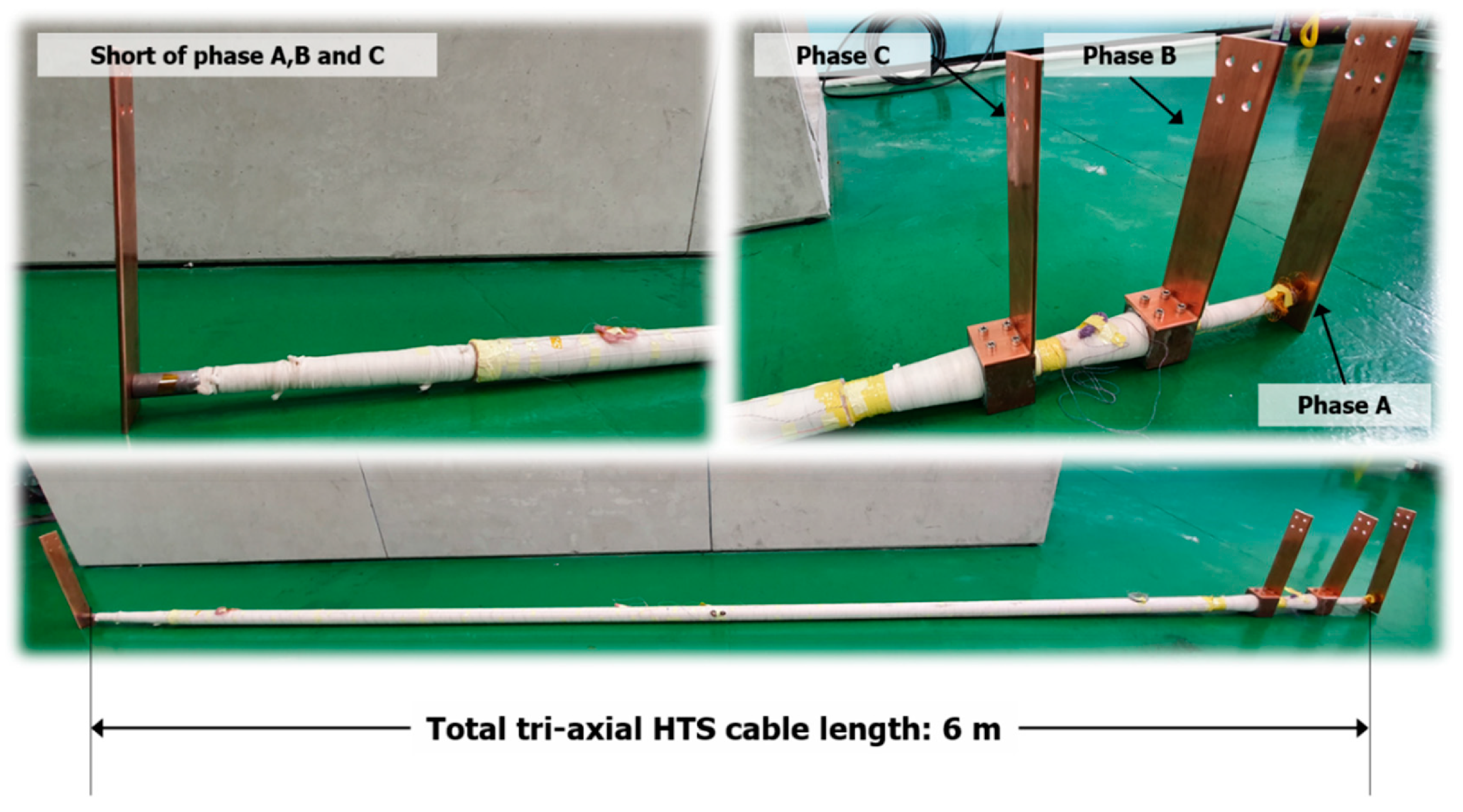
Lee et al., in [
10], analyse the performance of a 23 kV, 60 MVA class tri-axial HTS power cable (
Figure 2) to be used for real-grid applications in Korea. For this, they design and prototype a 6 m long cable for the measurement of its AC losses. The cable performance was also analysed under a finite element simulation. The AC losses are one of the most important factors in HTS power cables due to the design of the cooling system, which must be suitable to dissipate heat and maintain operating temperature for several kilometres of cable. In their research, the measured AC losses were over 250 mW/m, similar to the finite element analysis performed. The procedure for the measurements is extensively described in the paper. Measurements in DC and AC were performed. in DC, the critical current of each phase was determined. In AC, the losses were measured for each phase, as well as total cable losses. For accurate results, cancel coils were used to remove the reactive component of power, improving measurement accuracy of active power. This method is simpler and it is less expensive than using a lock-in amplifier, while maintaining the same level of precision [
9].
The purpose of the research in [
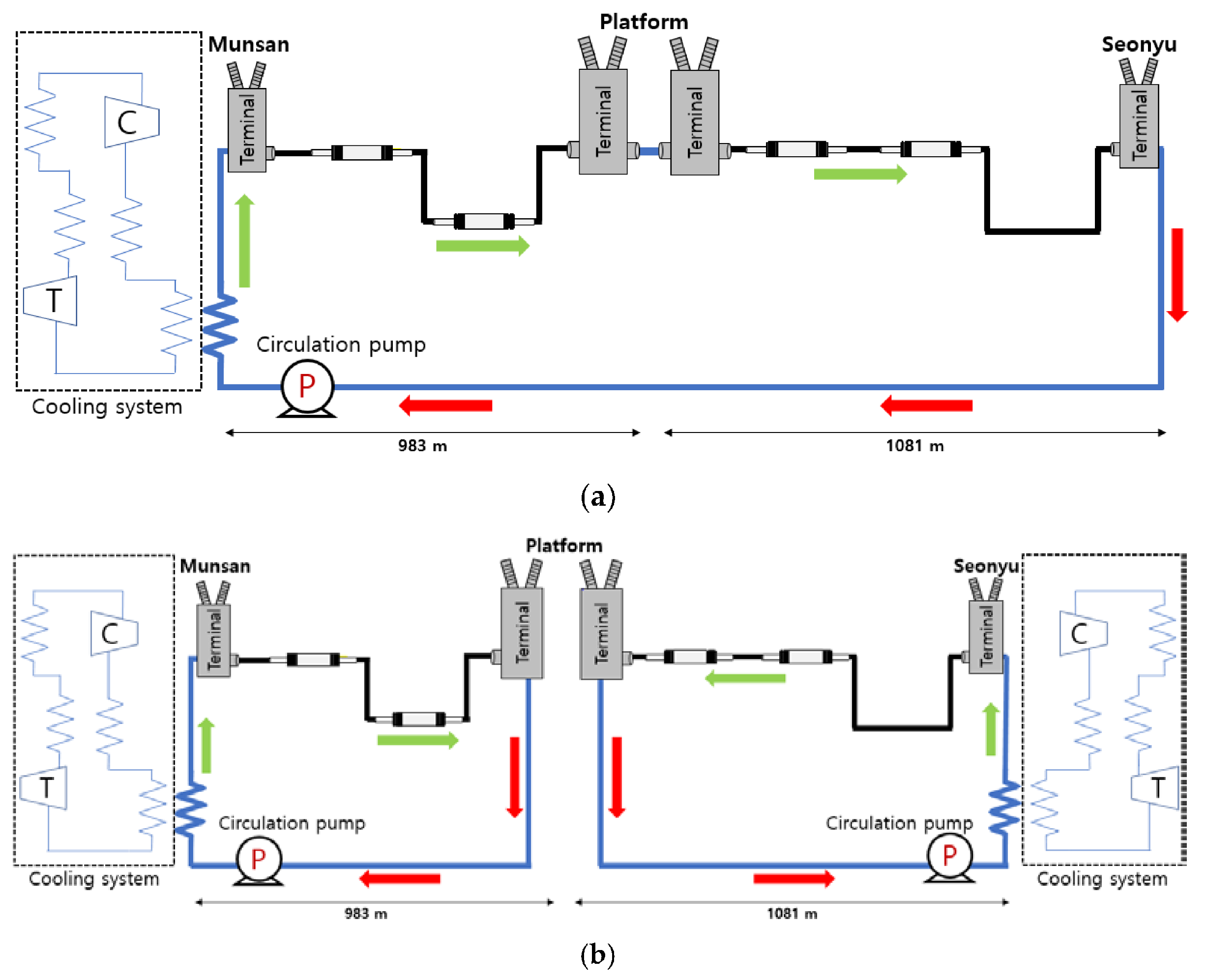
10] is to determine the cooling capacity and mass flow rate of the cooling systems. In this direction, Choi [
11] conducted an extensive analysis of a 23 kV, 60 MVA, tri-axial HTS power cable, now 2 km long, which connects two substations in Korea, the Munsan and Seonyu substations, to increase the power grid’s stability. Choi et al. made a thermo-hydraulic analysis of the HTS power cable, to determine the proper mass flow rates of subcooled LN2 that meet the required operating temperature and pressure. The analysis was made under four different configurations:
Single cooling system with an external return path;
Single cooling system with an internal return path;
Dual cooling system with an external return path;
Dual cooling system with an internal return path.
Single or dual cooling means that there is one cooling system on in only one substation or in both substations, respectively (
Figure 3), while external and internal describe if the LN2 returning to the cooling system goes outside or inside the power cable, respectively. Their analysis reaches the conclusion that for the external return path of the single cooling system and the dual cooling system, there is an adequate mass flow rate range. However, the internal return path cannot be operated in the single and dual cooling systems in the Seonyu-to-platform section in spite of the low heat loss feature of the internal return path (
Table 1). To operate the cooling system with an internal return path, the flow area should be increased, or a cable cryostat with a high allowable pressure should be used. They believe that this thermo-hydraulic analysis model and its results will be used as a design and operation guide for a cryogenic cooling system for the future installation of the tri-axial HTS power cable between the Munsan and Seonyu substations.
Another important aspect in the research of HTS power cables is the analysis of fault events. When in a fault situation, the HTS cable can be in considerable high current transportation, and in this case, it could result in quenching and irreparable damage. This is due to an increase in power losses in the HTS power cable, which the cooling systems are not suitable for long running times. In these ways, ref. [
12] considers a simulation of a power grid using an HTS power cable, with a copper stabiliser, connected in parallel to the HTS power cable, for fault situations. The simulation environment considers electromagnetic aspects of the cable in conjunction with its thermodynamic behaviour. It was developed an algorithm to calculate the HTS resistivity regarding its critical current and its temperature. In this ways, in a fault situation, the three states of the HTS cable, superconducting, flux flow, and normal state, are considered and parameters such as current transportation, temperature, and power dissipation can be computed. In this sense, this model can predict the behaviour of HTS cables under a fault situation, which is an important feature for the design of HTS cables for real-grid applications. To further validate these types of models, experiments regarding fault situations and HTS dynamic behaviour in fault situations should be performed.
4. SC Fault Current Limiters
Superconductor Fault Current Limiters (SFCL) are important, especially in DC systems. Unlike AC systems, there is no zero-crossing in DC power systems, which makes it hard to interrupt large short-circuit fault currents. Therefore, SFCLs are used to limit the DC current in fault conditions, to ease the burden of DC circuit breakers (DCCB). The work from Dao and Lee et al. [
13,
15] study the use of a Saturated Iron-Core Superconducting Fault Current Limiter (SI-SFCL) for DC power systems. SI-SFCLs are SFCLs that use a transformer configuration, such that the primary side is connected to the DC power grid, and the secondary side is connected to the SFCL. The coils are wound in opposite directions. The secondary side saturates the iron-core under normal operation of the DC power grid. When a fault occurs in the primary side, the current in the primary increases, and since the coils are wound in anti-series, the iron-core falls bellow saturation, which increases the inductance seen from the primary. This results in a lower peak fault current and higher rise time. For the research of SI-SFCLs, Dao et al. [
13] developed in 2020 a laboratory-scale SI-SFCL to operate at 500 V, 50 A, and with a DC power system. Experiments were set up to analyse operating conditions and characteristics of the SI-SFCL regarding the characteristics of the coils of the primary and secondary side. For the primary coil, three bobbins were developed: a solid aluminum structure, an aluminum-cutting structure, and a glass-fibre-reinforced polymer (GFRP) structure. These structures were made to compare the losses due to eddy currents and assess how they impact the current peak and rise time. The secondary coil is made of SuNAM SC tapes to reduce costs. The results show that the Al-cutting and the GFRP bobbins can limit current in the 70–75% range of full short-circuit (500 A), which was the intended design. A 3D FEM model was also developed, showing similar results. Regarding a cost analysis, the Al-cutting bobbin is better suited due to its lower costs compared with GFRP. Dao et al. are confident that the results can be effectively applied to large-scale SI-SFCL development research on multi-terminal HVDC power systems.
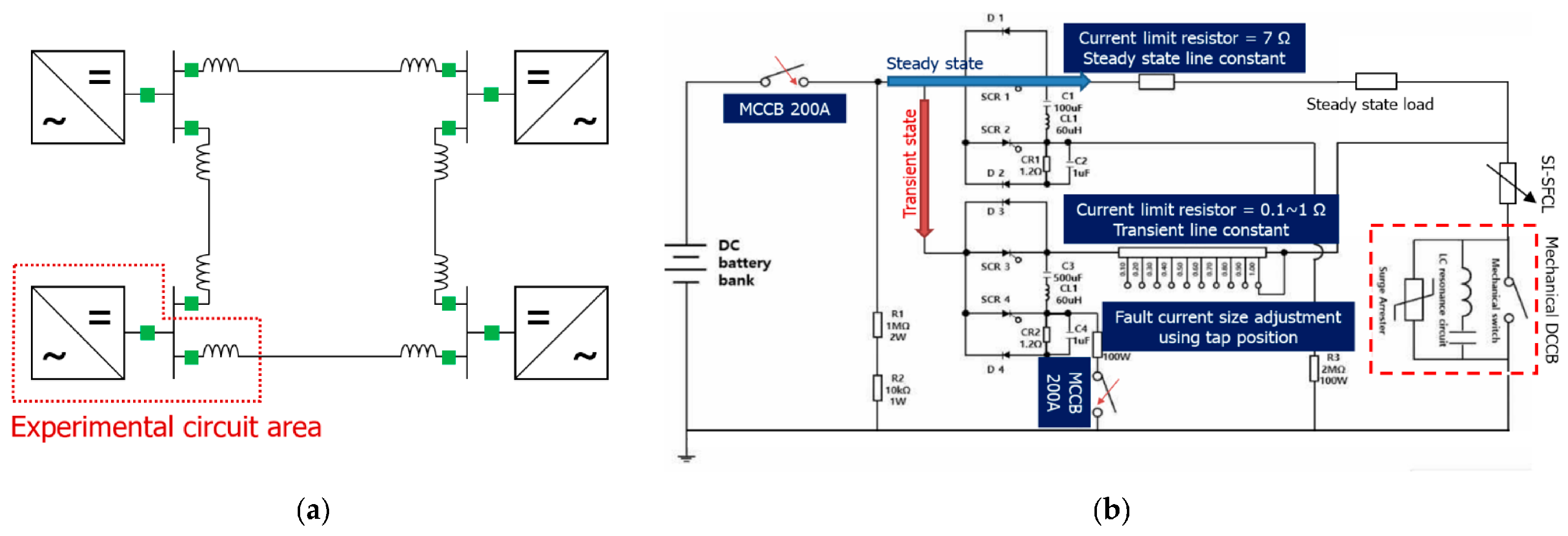
The SI-SFCL received updates later in [
15], now with a combined analysis of the SI-SFCL with a DCCB. Lee et al. constructed and studied a protection system combining the SI-SFCL and a mechanical circuit breaker that can be applied to a multi-terminal DC grid systems (
Figure 4). Their fault current limiting and interrupting characteristics were experimentally analysed. In order to evaluate the transient characteristics and performance of the SI-SFCL, a model to compute the dynamic behaviour of the SI-SFCL inductance was proposed and applied. Another lab-scale 500 V, 50 A DC system was developed, and the fault current of the system was set to 500 A. a DCCB with the appropriated rated capacity was designed and manufactured to conduct an interrupting test against faults in combination with the SI-SFCL, and their interaction was verified through the experiment. The results show that the CB capacity can be reduced to withstand lower currents, but the fault pick-up time was delayed by the SI-SFCL. With these results, they presented a mitigating solution to detect the faults early so the CB pick-up time remains short. The validity of the proposed fault detection method was verified by applying it to a simulation circuit reflecting the experimental system. As a result, the DCCB opening was made within 3.5 ms, and the total fault clearing time was also reduced by about 40 ms compared with the experimental result.
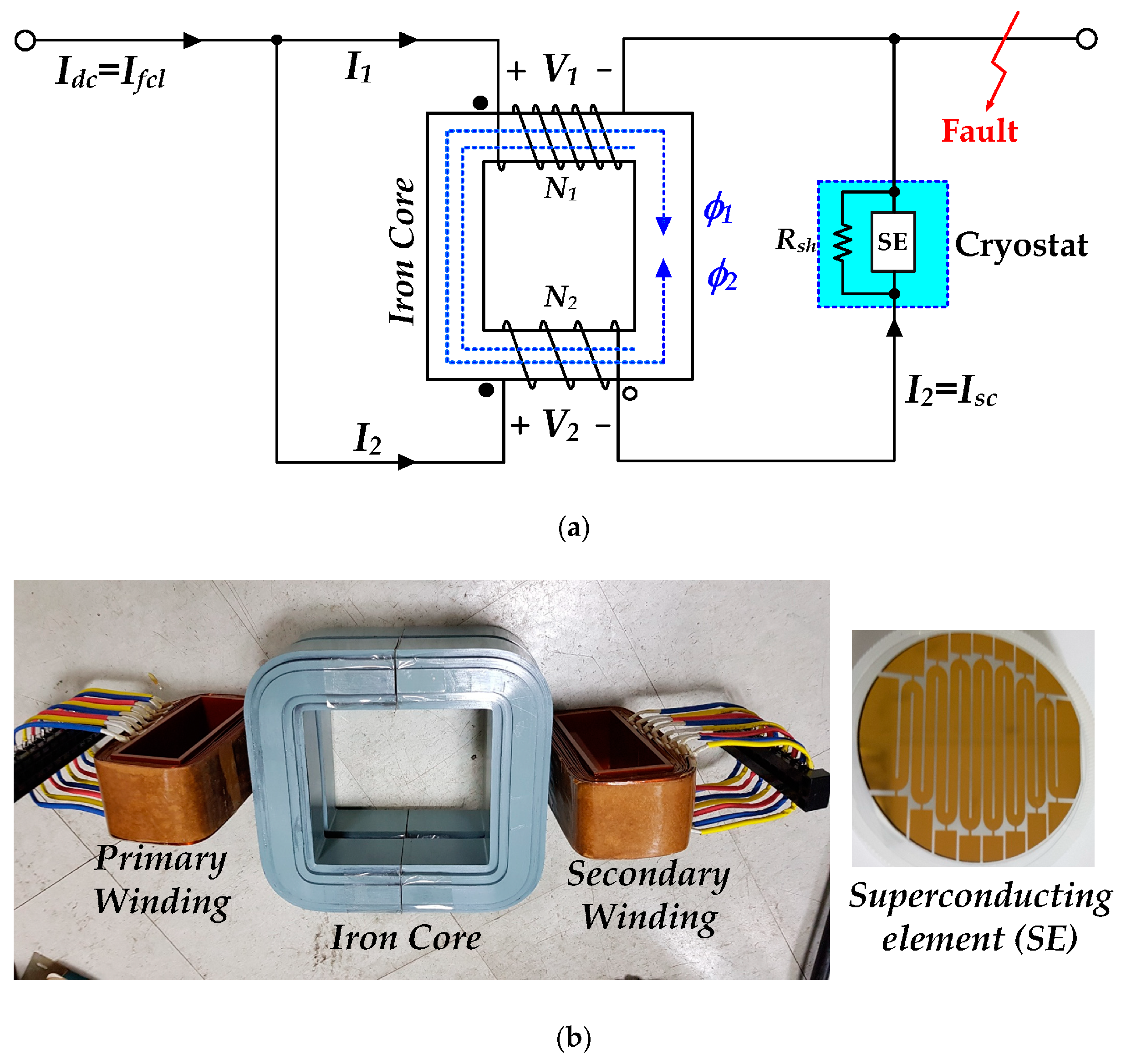
Another approach in current limiting technology is in Kim et al. [
14], in which a flux-coupled-type SFCL is used. The schematic of the circuit, as well as the real circuit, is shown in
Figure 5. This is closely related to the SI-SFCL, but the superconductor is integrated in the main circuit. When at normal operation, all the current passes through the superconductor. When a fault occurs, the superconductor starts to quench, and the current divides into the two windings of the transformer. Their interaction changes the total magnetic flux inside the magnetic core, effectively changing the line impedance, affecting the peak fault current and rise time. Kim et al. studied this type of flux-coupled SFCL, making winding configurations in series and anti-series, what they call subtractive and additive wiring, respectively. An experimental setup is made to test the SFCL under additive and subtractive wiring, with a controlled fault lasting 100 ms. The results show that from when the fault occurs to about 25 ms after, the fault currents are 50% lower using their SFCL technology than without it and using additive wiring. With subtractive winding, the transient time rises to about 50 ms, which creates a good safety zone for the DCCBs to trip. One identified problem is the remnant magnetic flux that is sustained in the magnetic core, which shifts the operating point of the SFCL. This needs to be addressed to identify which way the remnent magnetic flux can be removed from the magnetic core.
5. Superconducting Electric Machines
Superconducting (SC) technologies have been identified as potential materials to expand the current limits of electrical machines. Due to their intrinsic near-zero DC resistivity, SC materials can be used as tapes, to increase the loading capabilities of electrical machines, or as bulks to shield or trap high magnetic fluxes. The literature presents us with some examples of superconducting field-winding synchronous machines already developed and tested for marine applications using low-temperature superconductors. With the emergence of high-temperature superconductors (HTS), which can achieve their superconducting state at liquid nitrogen temperature, a renewed interest in SC electrical machines has emerged. Today, the main barriers to the development of commercial HTS electrical machines reside in their non-negligible AC losses, minimum bending radius, cooling requirements, and superconducting tape protection.
The electrification of the industrial and transportation systems has been identified as a key path towards the mitigation of climate change in the near future [
16]. In [
17], the authors present a review of the potential use of superconducting electrical machines for the propulsion systems of hybrid-electric aircraft (HEA) and all-electric aircraft (AEA). The main issues related to the development of electric aircraft are the energy sources and the high specific power requirements for electrical systems. While in HEA gas turbines can still be used for the power generation, in AEA, today, only batteries and fuel cells can be considered as available options. The authors present a comparison study between using kerosene as fuel or batteries and fuel cells as energy storage for a typical 200-passenger commercial aircraft. Compared to kerosene, batteries would require 32 times more weight and 10 times more volume for the same stored energy, which makes them impractical for passenger aircraft. However, fuel cells powered by liquid hydrogen are good candidates for AEA applications because they present four times more mass-specific energy with one-third of the volume-specific energy of kerosene. In addition, liquid hydrogen at 20 K could be used to cool the SC electrical machines.
Regarding SC electrical machines, these have been identified as a potential technology to reach the target of specific power required for aircraft applications: >10 kW/kg. In [
17] are listed several types of SC machines with their specific power, ranging from tens of kW to tens of MW, with efficiencies between 94% to 99.5%,
Table 2. The most common type of SC machine already built and tested is the low-temperature superconducting field windings synchronous machine (FWSM). The FWSM avoids the disadvantage of AC losses using SC tapes for the DC excitation of the FWSM, allowing high values of magnetic flux densities. Other types of SC machines are also being designed to further expand their specific power. Air-core radial flux machines allow removing the limitation of the iron core saturation, thus increasing the flux density inside the machine. The impact of AC losses on these types of machines is a current research topic, as removing the iron typically increases the magnetic field crossing the SC tapes, thus decreasing their critical current and increasing their AC losses. Axial-flux superconducting machines are also being developed to allow simple superconducting windings configurations, dual-rotor topologies, and light modular designs, which can facilitate the cooling of the SC parts. These are of particular interest for aircraft applications.
A method to improve the superconducting coil stability, against the damage occurred from quenching, is by using no-insulation (NI) superconducting coils. When no insulation is added between turns, a quench automatically bypasses to an adjacent turn when it occurs, protecting the quenched turn from damage. However, this technique presents some charge/discharge delay problems that make it difficult to be used in electrical machines. In Ref. [
18], the authors investigate the charge/discharge problem of NI HTS coils used in an HTS homopolar synchronous machines,
Figure 6. Firstly, the authors compare the charging/discharging performances of four coil configurations: (a) with turn-to-turn insulation, (b) no-insulation, (c) insulation every eight turns, and (d) insulation every four turns. For the insulated coil, results show that, in the center of the coil, the magnetic field is in phase with the current behavior, without any delay. However, for the no-insulation coil, there is a lag between the magnetic field and the current due to the leakage current between turns, especially for the discharge stage. Adding insulation every eight and four turns helps to reduce this delay, however, with a cost of reducing quench protection.
After testing the applicability of NI HTS coils, the authors designed a 110 kW HTS homopolar synchronous machine and tested the influence of using NI HTS and partial-insulated (PI) HTS field coils. The time constant value obtained for the PI coil is about 224 min, which is about 42% of the one obtained for the NI coils. However, it was found that a 7 h period would still be required to fully excite the HTS field coil of the homopolar synchronous machine, and it would be impractical to control them by regulating the field current. Therefore, while HTS homopolar synchronous machines have a great potential to be used in high specific power applications, these still require further development.
Concurrently to rotary motors, linear induction motors (LIM) may also allow extending the current limitations of electric transportation systems, such as in electric trains. In [
20], the authors present an overview of linear transportation systems (LTS) and focus on the application of LIM as the LTS propulsion. While typically linear induction motors present lower efficiencies than rotary motors, these avoid using gearboxes, and their disadvantage related to the lower efficiency diminishes when integrated with the transportation system. In the case of electric trains, LIM allows higher acceleration and braking rates, because they do not rely on the adhesion of wheels to the track, and allow sharper curves, providing more flexibility and reducing the cost of the system. The main types of levitated LTS are typically divided into permanent magnet (PM) or superconducting levitation systems, where the latter shows higher potential for achieving higher speeds. In 2015, an SC-Maglev train of the Central Japan Railway Company broke the train speed world record, achieving 603 km/h.
In addition to the overview of linear transportation systems in [
20], the authors also focus on the main aspects of the design and control of LIM. The authors believe that future research on LIM technologies should focus on increasing their efficiency as superconductors, based on new designs and using advanced materials. In addition, attention should be given to their command and control. Typically, the LIM is supplied by a PWM voltage inverter that converts the thrust command into the current at a desired frequency. However, due to the asymmetry of the LIM, the three-phase currents differ in phase and magnitude, and thus the impedance of the system must be determined for proper command.
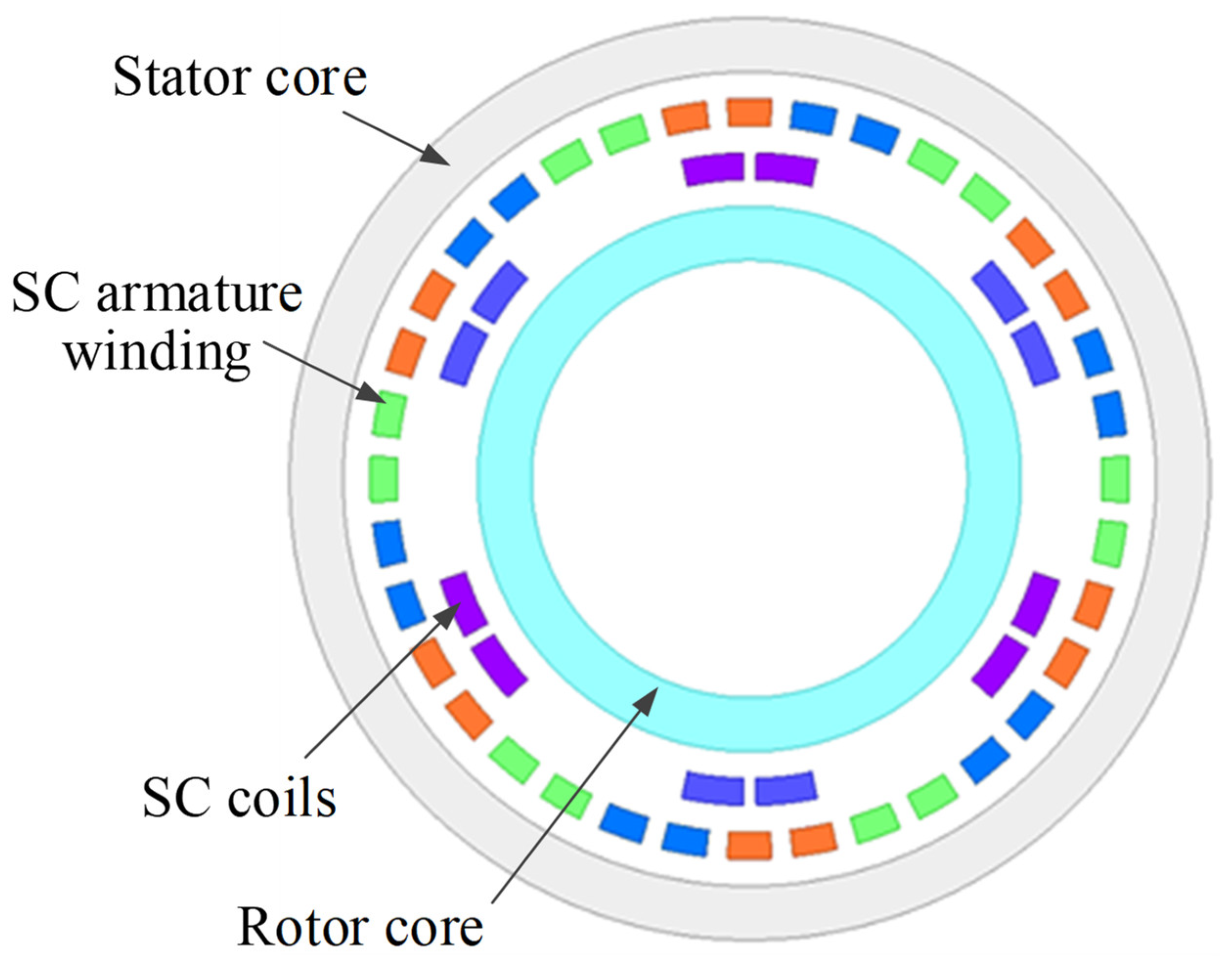
Superconducting electrical machines have also already shown advantages to be used in wind turbine applications. The EcoSwing project is one example of a research project where a full-scale direct-drive HTS generator was designed and tested in a wind turbine. In Ref. [
19], the authors focus on the design of a 10 MW, 10 rpm fully superconducting direct-drive wind generator, with special attention to the AC losses of the SC stator windings. Considering separate cryostats for the stator and rotor coils, the generator geometry is optimised to achieve 10 MW while maximising the output power per meter (volume-specific power),
Figure 7. For safety operation, the AC current of the stator coils is set equal to 0.55 of their critical current, while the rotor DC current to 0.75 of the critical current. Results show that, with the increase in the number of pole pairs, the active material weight decreases, while the AC stator coil losses increase due to an increase in electric frequency required to operate the generator at 10 rpm. The authors selected an optimised design with a good trade-off between lower AC losses, shorter SC lengths, and small active power weights. The SC generator presents 48 poles, 211.7 km of superconducting tapes, 22.8 tons of active material, and 40.1 kW of stator AC losses for a 10 MW and 10 rpm of output power and speed. In addition, the authors present some alternatives to reduce the impact of AC losses: reducing the width of the SC tapes from 4 mm to 1 mm, increasing the distance of the racetrack coils, reducing the number of coils in one slot, and decreasing the temperature of the SC coils.


