Abstract
This work aims to present an electrical power management system, between a photovoltaic generation system and a battery energy storage system, by using a low-power dual-stage microinverter connected to the electrical distribution network, configuring a nanogrid. The presented system is capable of performing the active power injection of the photovoltaic arrangement, increasing the availability of electrical energy through a maximum power point tracking algorithm. The system is also able to manage the processes of the charge and discharge of the battery system, where the energy storage system will serve as grid support when renewable power is not available. Furthermore, to ensure the quality of electric energy the proposed microinverter also has the characteristic of parallel active filter for suppression of harmonic currents and reactive compensation of local load current, ensuring the quality of electric energy. As a result, this work presents the system topology, modeling and control of electronic converters, the management strategy with its modes of operation and the results of numerical validation of the proposed system.
1. Introduction
The current scenario of the distribution system (DS) is in a process of transformation and adaptation due to the significant increase of nonlinear loads connected to the power grid at all voltage levels, which in turn end up compromising the electric power quality (EPQ) of the entire system [1,2]. As, for example, non-linear loads, we can list inverters on grid, converters for machine drivers, controlled and uncontrolled rectifiers, keyed sources, among others.
As a result of the increasing insertion in the DS of equipment with non-linear characteristics in residential and industrial applications there is an increase in the indexes of electromagnetic disturbances that end up distorting the waveform, causing an increase in electrical losses, untimely failures and in extreme cases until the burning of connected electronic devices or at the point common coupling (PCC) of the power grid [3,4,5,6,7,8].
In view of the above, we highlight the importance of studying the development of systems and equipment with a better EPQ, where the continuity of supply is also a determining factor, ensuring energy security for systems with critical loads and increasing the reliability of the system where they are inserted.
Added to the problems already existing in DS, in the last decades there has been an increase in distributed generation systems (DG) and models of microgrids involving hybrid systems with distributed generation and storage connected to the DS, causing growth of research with distributed generation and models of microgrids involving hybrid systems with distributed generation and storage connected to it [9,10,11,12,13,14,15,16].
Currently, there has been a growing interest in research on distributed hybrid systems composed of renewable sources (solar and wind). In addition, energy storage can be combined to mitigate the fluctuation and oscillation of power injected into the DS, consequently becoming a system with the more reliable characteristics of electric power dispatch energy availability [17,18,19,20].
In addition to the microgrids system, there is the emergence of the concept of nanogrids, defined as small modular load blocks that correspond to low-power management within a given microsystem and/or in the management of a set or a point load [21,22,23,24,25,26,27,28,29]. Research on nanogrids has pointed to the development of management systems that can ensure the supply and EPQ to the consumer in reduced amounts of energy [30] and to ensure compliance of these systems, management and control algorithms are required [31].
Thus, knowing the inconsistency in generation using alternative sources and the difficulty of predicting their behavior, the use of these sources as a reliable solution becomes complex, that is, the use of this type of solution is applicable only in remote networks, where the electrical network utility is not available and the quality of the energy produced is not of crucial or strategic importance. Given the limitations and difficulties in the operation of power generation that employ alternative sources, ways are sought to make this type of the solution more reliable, presenting a minimum availability during its process. Thus, it can be considered a reliable and available source, no longer just an ecologically correct source, to become a viable alternative source. Another problem related to the "random" variable nature is power swings. These cause variations in the voltage of the network in addition to reverse flow in distribution transformers, which causes problems with power quality, tap switching and voltage regulators, so a structure that eliminates or smooths sudden power fluctuations in the distribution network has great impact on the quality of electrical energy.
In view of the above, this work presents a proposal of management and control topology of a low-power nanogrid that contemplates the active energy conditioning through a complete bridged microinverter, as well as the management and control of an energy storage system through a buck-boost converter and the extraction of maximum power from a photovoltaic system, aiming to ensure the supply and/or self-consumption of electricity through a boost converter.
The contribution of this research consists in the presentation, through analytical and simulation results, of a nanogrid system with double stage of energy conversion using the technique of tracking the maximum power point perturb and observes. (MPPT-Maximum Power Point Tracking) that perturb and observes for maximum efficiency of the photovoltaic (PV) system, where simultaneously, both the injection of active energy into the power grid (when connected), load maintenance (when isolated) and the active power conditioning are performed.
This paper is organized as follows: Section 2 presents the topology of the nanogrid as well as the basic concept of the devices involved. In Section 3, the electrical schematics of the nanogrid are presented, the flowchart of the MPPT method used, the control strategies of the system, the SRF (Synchronous Reference Frame) system. In Section 4 the proposed method of managing the nanogrid is discussed. Finally, the results and discussions are presented in Section 5 and Section 6, respectively.
2. Description of Nanogrid with Active Energy Conditioning
The proposed nanogrid structure is presented in Figure 1. This configuration manages a low-power generating source, a photovoltaic panel, a lithium battery, and linear and nonlinear priority loads.
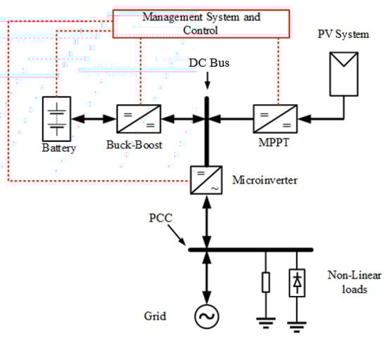
Figure 1.
Topology of nanogrid.
The objective of the proposed nanogrid is to optimize energy resources in a decentralized way, regardless of the presence of the conventional electricity grid. Therefore, the charging, storage and power conditioning devices of the nanogrid are low power. Where the PV arrangement consists of only one module, the storage system is a small battery and the loads are residential in size. As this electricity grid with low energy density, all energy conversion devices and generating source must be maximized to increase the overall yield of the nanogrid. To this end, in the PV generating sources, techniques have been systematically used to Maximum Power point tracking MPPT) [32,33,34,35]. On the other hand, the effects caused by partial shading can affect the maximization of energy produced from photovoltaic systems. However, using a single panel as a power source minimizes the problem of partial shading. Typically, MPPT techniques, which are based on hill climbing strategies (HC), such as Incremental Conductance–IC or Perturb & Observ–P&O [34], have been used to perform power point (MPP ) tracking of the photovoltaic arrangement.
These MPPT algorithms based on the IC and P&O methods perform well. Simultaneously with the optimization of the energy injection produced from the photovoltaic arrangement, the proposed nanogrid system also considers the active energy conditioning, which includes the suppression of harmonic currents of the load, as well as the compensation of reactive power. In other words, nanogrid also performs the active parallel power filter function [36,37,38,39,40,41,42].
In this case, regardless of the linear or nonlinear characteristics of the load, the drained current of the power grid will always be sinusoidal, with low harmonic content. Thus, energy quality indicators are improved, such as harmonic pollution reduction factor and power factor (PF). A DC-DC boost converter and a nanoinverter connected to the electrical grid comprise the respective first and second stages of power conversion of the PV system implemented in this paper. In the nanogrid system with PV power, while the DC-DC converter performs the MPPT function, an SRF current reference generator algorithm calculates the reference current that will be synthesized by the nanoinverter connected to grid tie.
Therefore, such a current is composed of the following components: (i) active component, which is proportional to the energy produced by the photovoltaic array; (ii) reactive component, which is proportional to the load’s reactive power compensation portion; and (iii) harmonic components, as dependent on non-linear load characteristics. However, due to the simultaneous operation of active power injection and reactive power compensation, or even the SRF must limit, when necessary, to avoid overloading the nanoinverter AC current, since the overloading the active power of the PV system must, be processed by the same. A system based on the SRF system is used to load the harmonic and reactive components of the load current [39,40,41]. Furthermore, the phase angle detection system (PLL) is used to estimate the phase angle () of the lattice, which is used to calculate, as a unit vector calculation system, sin() and cos(), employed in the SRF [42].
3. Nanogrid Model
Figure 2 presents the complete scheme of the proposed nanogrid with active energy conditioning. The structure consists of a photovoltaic system, a battery, a nanoinverter and connection to the single-phase electrical power grid. The topology is composed of a PV arrangement followed by the DC–DC voltage elevator stage (boost converter) where the MPPT-P&O algorithm is responsible for maximizing the power extraction of the PV module. By sharing the same DC bus, a bidirectional buck-boost converter is responsible for charging and recharging the battery, injecting or absorbing power from the bus. The full-bridge nanoinverter is responsible for the connection between the photovoltaic module and battery with the power grid and the loads. For the coupling of the system with the electrical power grid and the loads is a transformer that ensures the galvanic insulation of the system and the adequacy of the voltage level is used. Within the proposed topology of the nanogrid, a nonlinear single-phase full bridge rectifier load of type RL and RC will also be coupled in order to validate the active energy conditioning ensuring higher quality in the PCC.

Figure 2.
Proposed nanogrid structure with active energy conditioning.
3.1. Photovoltaic System Model
For the modeling of the photovoltaic system, the equivalent circuit of the PV cell is shown in Figure 3 [43].
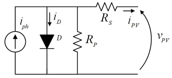
Figure 3.
Equivalent circuit of the photovoltaic cell.
Here, is the photocurrent; is the diode current; represents the output current of the PV cell; is the output voltage of the photovoltaic cell. Furthermore, series and parallel resistors are represented by and , respectively. Input quantities of the photovoltaic cell model are Solar radiation (G) in and temperature (T) in Kelvin, respectively. All parameters are obtained under standard test conditions (STC–Standard Test Condition). The current and voltage of the equivalent circuit can be obtained by solving the equations:
The quantities and constants of the equations are described as: reverse saturation current; ideality factor of the junction of the diode; is the Boltzmann constant; and are the short circuit current and open circuit voltage respectively; is the temperature coefficient; is the nominal reference temperature in Kelvin; is the reverse saturation current in STC; is the band energy of electron 1.1 eV; q is the charge of the electron. To obtain the voltage of a photovoltaic module, simply multiply the number of cells by the voltage obtained from the model.
3.2. Boost Converter Control Using the MPPT-P &O Algorithm
As a response to the mathematical model of the photovoltaic module, a non-linear relationship between voltage and current is obtained. For this reason it is necessary to use MPPT. In this paper, the P&O technique was used, as it is a well-used technique with good traceability, it requires low computational complexity when compared to other MPPT techniques, another justification for the use of this method is that the implemented nanogrid will be composed of a single photovoltaic module where the partial shading problem is minimized. Figure 4 presents a flowchart of the MPPT-P&O algorithm.

Figure 4.
MPPT − P&O algorithm flowchart.
Here, D is the duty cycle of the boost converter, and inc is the increment step of the duty cycle. The boost converter linked to the photovoltaic system will be responsible for injecting current into the DC link. In this case, if the bus voltage is exceeded, there is an excess of energy and the management system will be responsible for allocating this energy, whether it is used to charge the battery, inject it into the electricity grid or supply the load, both in islanded and connected states.
3.3. Battery and Supercapacitor Control Structure
Control of the energy storage system is carried out by a bidirectional buck-boost converter [44], allowing energy to flow in both directions, from the battery to the DC bus or from the DC bus to the battery. The control allows to operate in constant current and constant voltage mode for battery optimization. In addition, the buck-boost converter will be responsible for controlling the energy flow in a supercapacitor responsible for the high-frequency dynamic response of energy required by the system. Figure 2 shows diagram of the two-phase soft-switching bidirectional DC converter control, one responsible for processing power from the batteries and the other for the SC. The battery and the SC are positioned on the low voltage side and the photovoltaic source and electrical grid are coupled to the high voltage side (DC bus) where this is considered the main bus of the nanogrid. The block diagram of the control shows how the load balancing process between the battery and the supercapacitor was designed.
The control loop in Figure 5 has internal current control loops for battery and SC, as well as external control loop for voltage stabilization. Any deviation of the DC link voltage from the reference voltage is compensated by the voltage controller to produce the total current reference . The reference current is obtained by subtracting from itot-ipv which is separated into two components, through an LPF low pass filter. The output component of the LPF serves as a current reference for the battery as it has a low frequency value in steady state. To obtain the current reference for the , it is necessary to subtract from the output component of the LPF , thus obtaining . The component has fast transient action, therefore it serves as a current control reference for the . The parameter indicates whether the battery will be charged or discharged according to its signal, as well as limiting the current rate of the battery according to its SOC charge state. The transition between discharge (boost mode) and load (buck mode) modes of the bidirectional converter can be easily achieved by complementary switching in the devices of each switching branch. Therefore, a unified controller is tolerable for both modes.
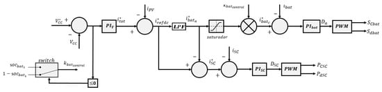
Figure 5.
Battery and supercapacitor control block diagram.
As it is a modular system, other batteries can be added to the system. Therefore, in this work a parameter was defined according to (5) where it is responsible for a proportional share of the control action in the DC bus stabilization process.
The parameter is calculated by normalizing the total capacity of the system.
where n is the number of batteries associated in the system and is the capacity of each battery and is the sum of the battery capacities that can be added to the system.
Another determining factor for managing battery charge and discharge is the state of charge SOC, depending on the state of charge, the management system will make the best decision for the nanogrid operation.
3.4. Pll System
The PLL system used in this work estimate the phase angle of the voltage in the power grid, which is used to generate the coordinates of the unit synchronous vector that allow the calculation of the current (harmonic and reactive components) and the sinusoidal current (component active), which compose the reference current to be synthesized by the nanoinverter. Figure 6 presents the single-phase system adopted in this work, where its complete description is detailed in [41,42,45].

Figure 6.
Block diagram of the PLL algorithm.
3.5. Synchronous Reference Frame Method SRF
The SRF algorithm used considers the modified single-phase model to generate a fictitious stationary single-phase reference frame. According to Figure 7, the direct component (d axis) is composed of the sum of , which represents the fundamental active component of the load current, and , which represents the harmonic load current components on the d axis. As can be seen, is extracted using a second-order Butterworth low pass filter (LPF). On the other hand, the quadrature component (q axis) is composed of the sum of , which represents the fundamental reactive component of the load, and , the harmonic current components of the load on the q axis. Thus, full compensation is performed by compensating the currents and . The forward and quadrature currents of the SRF algorithm are obtained by:

Figure 7.
Synchronous Reference Frame method.
In this way, the complete reference current of the nanoinverter can be obtained by (9).
The gain K multiplying the output current of the algorithm must be set so that the maximum compensation current does not exceed the maximum current of the nanoinverter.
The current is defined by the PV module currents from the battery and supercapacitor current.
3.6. Nanoinverter Control Connected Mode and Islanded Mode
Currently, many control strategies are being developed for application in inverters such as: (i) hysteresis, (ii) predictive control, (iii) fuzzy logic, (iv) repetitive control, (v) neural networks, among others [46,47,48]. In all these control strategies presented, there is an increase in the complexity of the control design, decreasing the reliability of the system [49]. Therefore, dual-loop control using PID controllers is used in this work. This type of control features easy implementation, simple controller design and excellent performance. Figure 8 shows the block diagram for controlling the converter in grid-connected mode. Figure 9 shows the nanoinverter control loop where the islanded mode of operation is considered. In this case, the control loop acts in a contingency condition or isolated operation in order to generate a voltage in the PCC within the power quality parameters.

Figure 8.
Block diagram of grid connected mode inverter control loop.

Figure 9.
Block diagram of the grid-islanded inverter control loop.
For the energy source and storage system integration structure that is being presented in this work, it is expected that all the energy generated by the photovoltaic system will be made available on the DC bus, so to achieve this requirement, the control and management structure power needs to operate near the point of maximum power. In this way, the control of the voltage of the bus is in charge of the energy stores, which must supply/absorb probable lack/excess of energy in the nanogrid, maintaining the stability and availability of energy in the microinverter.
4. Nanogrid Management System
For the nanogrid management system, an algorithm was proposed that guarantees the service of small loads through the photovoltaic and battery system as shown in Figure 10. Within this structure, we can separate the process into two steps: (i) if the system is connected to the electrical grid or (ii) the system is operating in an islanded mode forming the nanogrid (indicate these steps in the flowchart). With the system connected, the priority will be the storage of energy in the batteries and maximum extraction from the photovoltaic system. Already operating in islanded mode, the battery assumes the energy demand of the load along with the photovoltaic system, if energy is available.

Figure 10.
Nanogrid Management System Flowchart.
5. Results
This section presents simulation results in order to evaluate the effectiveness and the steady state and dynamic performance of the proposed nanogrid. Matlab Simulink was used for the implementation of the system, as well as the generator of the current reference SRF, PLL, MPPT algorithms, the battery system, microinverter and DC-DC converters as well as the double loop PI controllers. The non-linear load consists of a diode full-bridge rectifier, followed by an RL load.
Table 1 shows the parameters of the nanogrid and control converters parameters shown in the Figure 2. The battery and supercapacitor parameters are shown in the Table 2. The Table 3 shows the electrical characteristics of the photovoltaic system used for power generation. The Table 4 shows the load parameters of the single-phase full bridge rectifier with inductive resistive load.

Table 1.
Nanogrid and Control converters parameters.
Table 2.
Battery and supercapacitor parameters.
Table 3.
Photovoltaic parameters.
Table 4.
Retifier load parameters.
Figure 11 presents the performance of the nanoinverter operating as an active power filter. It can be seen that the network current was compensated by obtaining a TDH level as indicated in Figure 12. The DC bus control dynamics can be seen in Figure 13. The bus reference voltage was 230V, due to its slow dynamics, necessary for system stabilization. An overshoot of 5% can be observed, which can be considered satisfactory.
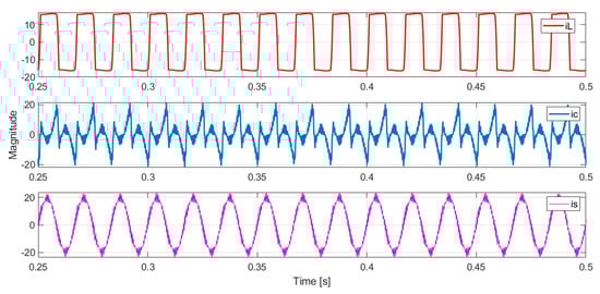
Figure 11.
Nanogrid system currents operating in connected mode: Load current ; mains current drain of grid power and compensation current.

Figure 12.
Rate harmonic distortion after compensation.

Figure 13.
DC bus.
The Figure 14 shows the harmonic distortion rate of the system without active filter compensation.

Figure 14.
Rate harmonic distortion before compensation.
Figure 15 shows the dynamic behavior of the battery and the supercapacitor on the nanogrid. It is possible to observe that the voltage of the battery and the supercapacitor are stabilized in the charging mode, this shows the robustness of the control during the transition from the operating mode.

Figure 15.
Battery and SC dynamics.
6. Discussion
A single-phase photovoltaic system connected to the bidirectional power grid with the ability to form a nanogrid was presented. As a result, the system presented a considerable reduction in the harmonic distortion rate caused by the load on the power grid, the DC bus control was satisfactory in the transient response and steady-state.. The photovoltaic system operating with active power conditioning capacity was tested, showing good performance. For this purpose, an implementation reference transformer to perform, simultaneously, an active power injection and power conditioning, enabling a power factor correction. A photovoltaic generator power optimization technique was performed using an MPPT-P&O. In addition, the power system operated satisfactorily when the system was operating in islanded mode, disconnected from the mains. As a result, a control and management system structure of the nanogrid elements was presented, allowing the increase of the system efficiency and ensuring power quality at the point common coupling.. The static and functional performances of the PV system were presented through simulation results.
Author Contributions
Conceptualization: F.M.d.O. and O.H.A.J., investigation and simulation:d. F.M.d.O. and O.H.A.J., wrote and final editing: F.M.d.O., O.H.A.J., F.S. and A.C.S.M. All authors have read and agreed to the published version of the manuscript.
Funding
This research was funded by PRPPG of the Federal University of Paraiba (UFPB). The O.H.A.J. was funded by the Brazilian National Council for Scientific and Technological Development (CNPq), grant number 407531/2018-1 and 303293/2020-9. This research was funded by Federal University of Latin American Integration (UNILA).
Institutional Review Board Statement
Not applicable.
Informed Consent Statement
Not applicable.
Data Availability Statement
Not applicable.
Acknowledgments
The authors would like to thank to the Federal University of Latin American Integration (UNILA), Federal Rural University of Pernambuco (UFRPE) and Federal University of Paraiba (UFPB) for financial supporting and facilities, Coordination for the Improvement of Higher Education Personnel (CAPES) and the Brazilian Council for Scientific and Technological Development (CNPq) for financial support.
Conflicts of Interest
The authors declare no conflict of interest.
References
- Junior, O.; Bretas, A.; Leborgne, R. Methodology for calculation and management for indicators of power quality energy. IEEE Lat. Am. Trans. 2015, 13, 2217–2224. [Google Scholar] [CrossRef]
- Crepaldi, J.; Amoroso, M.; Ando, O. Analysis of the topologies of power filters applied in distributed generation units—Review. IEEE Lat. Am. Trans. 2018, 16, 1892–1897. [Google Scholar] [CrossRef]
- Bastos, R. Sistema de Gerenciamento Para a Integração em CC de Fontes Alternativas de Energia e Armazenadores Híbridos Conectados a Rede de Distribuição via Conversores Eletrônicos; Universidade de São Paulo: São Paulo, Brazil.
- Chattopadhyay, S.; Mitra, M.; Sengupta, S. Electric power quality. Electr. Power Qual. 2011, 5–12. [Google Scholar] [CrossRef]
- Wang, F.; Duarte, J.; Hendrix, M.; Ribeiro, P. Modeling and analysis of grid harmonic distortion impact of aggregated DG inverters. IEEE Trans. Power Electron. 2010, 26, 786–797. [Google Scholar] [CrossRef]
- IEEE STD519–1992; IEEE Recommended Practices and Requirements for Harmonic Control in Electrical Power Systems. IEEE: New York, NY, USA, 1993.
- Prodist, A. Agência Nacional de Energia Elétrica-Procedimentos de Distribuição de Energia Elétrica no Sistema Elétrico Nacional, Módulo 8—Qualidade da Energia Elétrica. 2012. Available online: https://www.gov.br/aneel/pt-br/centrais-de-conteudos/procedimentos-regulatorios/prodist (accessed on 13 August 2013).
- Parhizi, S.; Lotfi, H.; Khodaei, A.; Bahramirad, S. State of the art in research on microgrids: A review. IEEE Access 2015, 3, 890–925. [Google Scholar] [CrossRef]
- Nejabatkhah, F.; Li, Y. Overview of power management strategies of hybrid AC/DC microgrid. IEEE Trans. Power Electron. 2014, 30, 7072–7089. [Google Scholar] [CrossRef]
- Samper, M.; Flores, D.; Vargas, A. Investment valuation of energy storage systems in distribution networks considering distributed solar generation. IEEE Lat. Am. Trans. 2016, 14, 1774–1779. [Google Scholar] [CrossRef]
- Daza, E.; Sperandio, M. The insertion of energy storage systems in power systems: A regulatory and economic analysis. IEEE Lat. Am. Trans. 2019, 17, 843–850. [Google Scholar] [CrossRef]
- Grisales, L.; Montoya, O.; Grajales, A.; Hincapie, R.; Granada, M. Optimal planning and operation of distribution systems considering distributed energy resources and automatic reclosers. IEEE Lat. Am. Trans. 2018, 16, 126–134. [Google Scholar] [CrossRef]
- Montoya, O.; Grajales, A.; Garces, A.; Castro, C. Distribution systems operation considering energy storage devices and distributed generation. IEEE Lat. Am. Trans. 2017, 15, 890–900. [Google Scholar] [CrossRef]
- Serrano-Canalejo, C.; Sarrias-Mena, R.; Garcia-Trivino, P.; Fernandez-Ramirez, L. Energy management system design and economic feasibility evaluation for a hybrid wind power/pumped hydroelectric power plant. IEEE Lat. Am. Trans. 2019, 17, 1686–1693. [Google Scholar] [CrossRef]
- Wiesner, A.; Diez, R.; Perilla, G. Energy Storage System from DC Bus with Port for Solar Module. IEEE Lat. Am. Trans. 2015, 13, 1376–1382. [Google Scholar] [CrossRef]
- Xu, M.; Wu, L.; Liu, H.; Wang, X. Multi-objective optimal scheduling strategy for wind power, PV and pumped storage plant in VSC-HVDC grid. J. Eng. 2019, 2019, 3017–3021. [Google Scholar] [CrossRef]
- Khalid, M.; AlMuhaini, M.; Aguilera, R.; Savkin, A. Method for planning a wind–solar–battery hybrid power plant with optimal generation-demand matching. IET Renew. Power Gener. 2018, 12, 1800–1806. [Google Scholar] [CrossRef]
- Pradhan, S.; Singh, B.; Panigrahi, B.; Murshid, S. A composite sliding mode controller for wind power extraction in remotely located solar PV–wind hybrid system. IEEE Trans. Ind. Electron. 2018, 66, 5321–5331. [Google Scholar] [CrossRef]
- Kumar, P.; Chandrasena, R.; Ramu, V.; Srinivas, G.; Babu, K. Energy management system for small scale hybrid wind solar battery based microgrid. IEEE Access 2020, 8, 8336–8345. [Google Scholar] [CrossRef]
- Pilehvar, M.; Shadmand, M.; Mirafzal, B. Analysis of smart loads in nanogrids. IEEE Access 2018, 7, 548–562. [Google Scholar] [CrossRef]
- Bagewadi, M.; Dambhare, S. A Buck-Boost topology based hybrid converter for standalone nanogrid applications. In Proceedings of the 2017 IEEE Second International Conference on DC Microgrids (ICDCM), Nuremburg, Germany, 27–29 June 2017; pp. 502–506. [Google Scholar]
- Jie, L.; Naayagi, R. Nanogrid for energy aware buildings. In Proceedings of the 2019 IEEE PES GTD Grand International Conference And Exposition Asia (GTD Asia), Bangkok, Thailand, 20–23 March 2019; pp. 92–96. [Google Scholar]
- Joseph, S.; Mohammed, A.; Dhanesh, P.; Ashok, S. Smart Power Management for DC Nanogrid Based Building. In Proceedings of the 2018 IEEE Recent Advances in Intelligent Computational Systems (RAICS), Thiruvananthapuram, India, 6–8 December 2018; pp. 142–146. [Google Scholar]
- Hinov, N.; Stanev, R.; Vacheva, G. A power electronic smart load controller for nanogrids and autonomous power systems. In Proceedings of the 2016 XXV International Scientific Conference Electronics (ET), Sozopol, Bulgaria, 12–14 September 2016; pp. 1–4. [Google Scholar]
- Joseph, S.; Ashok, S.; Dhanesh, P. Low voltage direct current (LVDC) nanogrid for home application. In Proceedings of the 2017 IEEE Region 10 Symposium (TENSYMP), Cochin, India, 14–16 July 2017; pp. 1–5. [Google Scholar]
- Joseph, S.; Ashok, S.; Dhanesh, P. An effective method of power management in DC nanogrid for building application. In Proceedings of the 2017 IEEE International Conference on Signal Processing, Informatics, Communication And Energy Systems (SPICES), Kollam, India, 8–10 August 2017; pp. 1–5. [Google Scholar]
- Joseph, S.; Chandrasekar, V.; Dhanesh, P.; Mohammed, A.; Ashok, S. Battery Management System for DC Nanogrid. In Proceedings of the 2018 20th National Power Systems Conference (NPSC), Tiruchirappalli, India, 14–16 December 2018; pp. 1–5. [Google Scholar]
- Malkawi, A.; Lopes, L. Control of the power electronics interface of a PV source in a smart residential DC nanogrid. In Proceedings of the 2016 IEEE Canadian Conference on Electrical and Computer Engineering (CCECE), Vancouver, BC, Canada, 15–18 May 2016; pp. 1–4. [Google Scholar]
- Schonardie, M.; Coelho, R.; Martins, D. Active and reactive power control in a three-phase grid-connected Pv power system using Dq0 transformation. EletrôNica PotêNcia 2013, 18, 1180–1187. [Google Scholar] [CrossRef]
- Brandão, D.; Marafão, F.; Farret, F.; Simões, M. Proposta de Metodologia para o Gerenciamento Automático de Sistemas Fotovoltaicos de Geração Distribuída. EletrôNica PotêNcia 2013, 18, 1257–1265. [Google Scholar]
- Brito, M.; Sampaio, L.; Melo, G.; Canesin, C. Contribuição ao estudo dos principais algoritmos de extração da máxima potência dos painéis fotovoltaicos. EletrôNica PotêNcia 2012, 17, 592–600. [Google Scholar]
- Coelho, R.; Dos Santos, W.; Martins, D. Influence of power converters on PV maximum power point tracking efficiency. In Proceedings of the 2012 10th IEEE/IAS International Conference on Industry Applications, Fortaleza, CE, Brazil, 5–7 November 2012; pp. 1–8. [Google Scholar]
- Femia, N.; Petrone, G.; Spagnuolo, G.; Vitelli, M. Optimization of perturb and observe maximum power point tracking method. IEEE Trans. Power Electron. 2005, 20, 963–973. [Google Scholar] [CrossRef]
- Liu, Y.; Chen, J.; Huang, J. A review of maximum power point tracking techniques for use in partially shaded conditions. Renew. Sustain. Energy Rev. 2015, 41, 436–453. [Google Scholar] [CrossRef]
- Wu, T.; Nien, H.; Shen, C.; Chen, T. A single-phase inverter system for PV power injection and active power filtering with nonlinear inductor consideration. IEEE Trans. Ind. Appl. 2005, 41, 1075–1083. [Google Scholar] [CrossRef]
- Silva, S.; Sampaio, L.; Oliveira, F.; Durand, F. Sistema fotovoltaico com condicionamento ativo de energia usando mppt baseado em PSO e malha feed-forward de controle de tensão do barramento CC. EletrôNica PotêNcia 2016, 21, 105–116. [Google Scholar] [CrossRef]
- Brandão, D.; Marafão, F.; Gonçalves, F.; Villalva, M.; Gazoli, J. Estratégia de controle multifuncional para sistemas fotovoltaicos de geração de energia elétrica. Braz. J. Power Electron. 2013, 18, 1206–1214. [Google Scholar]
- Campanhol, L.; Silva, S.; Goedtel, A. Filtro ativo de potência paralelo aplicado em sistemas trifásicos a quatro-fios. EletrôNica PotêNcia 2013, 18, 782–792. [Google Scholar]
- Angélico, B.; Campanhol, L.; Silva, S. Proportional–integral/proportional–integral-derivative tuning procedure of a single-phase shunt active power filter using Bode diagram. IET Power Electron. 2014, 7, 2647–2659. [Google Scholar] [CrossRef]
- Ferreira, S.; Pereira, R.; Gonzatti, R.; Silva, C.; Silva, L.; Lambert-Torres, G. Filtros Adaptativos Aplicados em Condicionadores de Energia. EletrôNica PotêNcia 2014, 19, 377–385. [Google Scholar]
- Poblador, M.; López, G. Power calculations in nonlinear and unbalanced conditions according to IEEE Std 1459–2010. In Proceedings of the 2013 Workshop on Power Electronics and Power Quality Applications (PEPQA), Bogota, Colombia, 6–7 July 2013; pp. 1–7. [Google Scholar]
- Bacon, V.; Silva, S.; Campanhol, L.; Angélico, B. Stability analysis and performance evaluation of a single-phase phase-locked loop algorithm using a non-autonomous adaptive filter. IET Power Electron. 2014, 7, 2081–2092. [Google Scholar] [CrossRef]
- Gow, J.; Manning, C. Development of a photovoltaic array model for use in power-electronics simulation studies. IEE Proc.-Electr. Power Appl. 1999, 146, 193–200. [Google Scholar] [CrossRef]
- Henze, C.; Martin, H.; Parsley, D. Zero-voltage switching in high frequency power converters using pulse width modulation. In Proceedings of the APEC’88 Third Annual IEEE Applied Power Electronics Conference and Exposition, New Orleans, LA, USA, 1–5 February 1988; pp. 33–40. [Google Scholar]
- Salameh, Z.; Casacca, M.; Lynch, W. A mathematical model for lead-acid batteries. IEEE Trans. Energy Convers. 1992, 7, 93–98. [Google Scholar] [CrossRef]
- Chang, E.; Guerrero, J. Fuzzy variable structure control for PWM inverters. In Proceedings of the 2011 IEEE International Conference on Fuzzy Systems (FUZZ-IEEE 2011), Taipei, Taiwan, 27–30 June 2011; pp. 609–613. [Google Scholar]
- Yilmaz, M.; Krein, P. Review of battery charger topologies, charging power levels, and infrastructure for plug-in electric and hybrid vehicles. IEEE Trans. Power Electron. 2012, 28, 2151–2169. [Google Scholar] [CrossRef]
- Wang, Q.; Rivera, M.; Riveros, J.; Wheeler, P. Modulated model predictive current control for PMSM operating with three-level NPC inverter. In Proceedings of the 2019 IEEE 15th Brazilian Power Electronics Conference and 5th IEEE Southern Power Electronics Conference (COBEP/SPEC), Santos, Brazil, 1–4 December 2019; pp. 1–5. [Google Scholar]
- Pradipta, A.; Riawan, D. Others Power flow control of battery energy storage system using droop voltage regulation technique integrated with hybrid PV/Wind generation system. In Proceedings of the 2018 International Conference on Information and Communications Technology (ICOIACT), Yogyakarta, Indonesia, 6–7 March 2018; pp. 202–207. [Google Scholar]
Publisher’s Note: MDPI stays neutral with regard to jurisdictional claims in published maps and institutional affiliations. |
© 2022 by the authors. Licensee MDPI, Basel, Switzerland. This article is an open access article distributed under the terms and conditions of the Creative Commons Attribution (CC BY) license (https://creativecommons.org/licenses/by/4.0/).